Hewlett Packard Enterprise WA2620EAGN Wireless LAN Access Point User Manual
Hewlett-Packard Company Wireless LAN Access Point
Contents
- 1. User's manual_new
- 2. Users manual new
User's manual_new

H3C WA2600 Series WLAN Access Points
Installation Manual
Hangzhou H3C Technologies Co., Ltd.
http://www.h3c.com
Manual Version: 5PW100-20081111

Copyright © 2008, Hangzhou H3C Technologies Co., Ltd. and its
licensors
All Rights Reserved
No part of this manual may be reproduced or transmitted in any form
or by any means without prior written consent of Hangzhou H3C
Technologies Co., Ltd.
Trademarks
H3C, , Aolynk, , H3Care,
, TOP G, ,
IRF, NetPilot, Neocean, NeoVTL, SecPro, SecPoint, SecEngine,
SecPath, Comware, Secware, Storware, NQA, VVG, V2G, VnG,
PSPT, XGbus, N-Bus, TiGem, InnoVision and HUASAN are
trademarks of Hangzhou H3C Technologies Co., Ltd.
All other trademarks that may be mentioned in this manual are the
property of their respective owners.
Notice
The information in this document is subject to change without notice.
Every effort has been made in the preparation of this document to
ensure accuracy of the contents, but all statements, information, and
recommendations in this document do not constitute the warranty of
any kind, express or implied.
Technical Support
customer_service@h3c.com
http://www.h3c.com

About This Manual
Organization
H3C WA2600 Series WLAN Access Points Installation Manual is
organized as follows:
Chapter Contents
1 Product Overview Introduces the hardware configurations,
appearance, and interfaces of the H3C
WA2600 Series WLAN Access Points.
2 Preparing for
Installation
Specifies the environmental requirements
for installing the H3C WA2600 Series
WLAN Access Points, presents installation
precautions, and introduces the installation
tools needed.
3 Installing the AP
Introduces how to install the H3C WA2600
Series WLAN Access Points and how to
connect the power supply units and the
Ethernet cable.
Conventions
The manual uses the following conventions:
Symbols
Convention Description
Means reader be extremely careful. Improper
operation may cause bodily injury.
Means reader be careful. Improper operation
may cause data loss or damage to equipment.

Convention Description
Means a complementary description.
Obtaining Documentation
You can access the most up-to-date H3C product documentation on
the World Wide Web at this URL: http://www.h3c.com.
The following are the columns from which you can obtain different
categories of product documentation:
[Products & Solutions]: Provides information about products and
technologies.
[Technical Support & Document > Technical Documents]: Provides
several categories of product documentation, such as installation,
operation, and maintenance.
Documentation Feedback
You can e-mail your comments about product documentation to
info@h3c.com.
We appreciate your comments.
Environmental Protection
This product has been designed to comply with the requirements on
environmental protection. For the proper storage, use and disposal of
this product, national laws and regulations must be observed.
i
Table of Contents
1 Product Overview .................................................................................1-1
Introduction.........................................................................................1-1
Hardware Configuration .....................................................................1-2
LEDs ...........................................................................................1-3
Interfaces....................................................................................1-5
2 Preparing for Installation .....................................................................2-1
Unpacking and Inspection..................................................................2-1
Preparing Installation Tools................................................................2-2
Examining the Installation Site...........................................................2-3
Installation Site Selection ...........................................................2-3
Temperature and Humidity Requirements .................................2-3
Power Supply..............................................................................2-4
Grounding and Lightning Protection...........................................2-5
3 Installing the AP....................................................................................3-1
Installation Flowchart .........................................................................3-1
Determining the Installation Position..................................................3-1
Installing the AP on a Wall .................................................................3-2
Installing the Wall-Mounting Bracket on the Wall.......................3-2
Installing the AP on the Wall-Mounting Bracket .........................3-5
Locking the AP onto the Wall-Mounting Bracket (Optional).......3-6
Connecting the Power Supply............................................................3-8
Local Power Supply....................................................................3-8
Power over Ethernet...................................................................3-8
Connecting the AP to the Network.....................................................3-9
ii
List of Figures
Figure 1-1 Typical networking using the WA2600 series ..................1-1
Figure 1-2 Appearance of the WA2600 series ..................................1-2
Figure 1-3 LEDs on the H3C WA2610E-AGN...................................1-3
Figure 1-4 LEDs on the H3C WA2620E-AGN...................................1-3
Figure 1-5 Interfaces on the H3C WA2610E-AGN............................1-6
Figure 1-6 Interfaces on the H3C WA2620E-AGN............................1-7
Figure 3-1 Installation flowchart ........................................................3-1
Figure 3-2 Screw hole locations and screw hole size .......................3-3
Figure 3-3 Install the wall-mounting bracket .....................................3-4
Figure 3-4 Fix the AP onto the wall-mounting bracket ......................3-6
Figure 3-5 Lock the AP onto the wall-mounting bracket....................3-7
Figure 3-6 Local power supply connection........................................3-8
Figure 3-7 PoE connection................................................................3-8
Figure 3-8 Connect the AP to the network ........................................3-9
iii
List of Tables
Table 1-1 Physical dimensions and weight of the WA2600 series ......1-2
Table 1-2 Supported protocols and chassis material.........................1-2
Table 1-3 Description of the LEDs on the WA2610E-AGN and
WA2620E-AGN...........................................................................1-4
Table 1-4 Descriptions of interfaces on the WA2600 series WLAN
access points..............................................................................1-8
Table 2-1 List of articles in the package ............................................2-1
Table 2-2 List of installation tools.......................................................2-2
Table 2-3 Environment specifications ................................................2-3
Table 2-4 Nominal voltage and frequency of the low-voltage AC power
supply .........................................................................................2-4
Table 2-5 Grounding and lightning protection requirements..............2-5

1-1
1 Product Overview
Introduction
The H3C WA2600 Series WLAN Access Points (hereinafter referred
to as the WA2600 series) are one of the 802.11n access point (AP)
product series developed by Hangzhou H3C Technologies Co., Ltd.
(hereinafter referred to as H3C). The WA2600 series can serve as FIT
APs to cooperate with wireless local area network (WLAN) switches
or access controllers to provide wireless access for WLAN users.
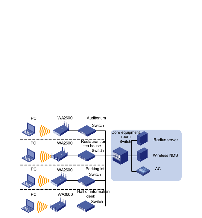
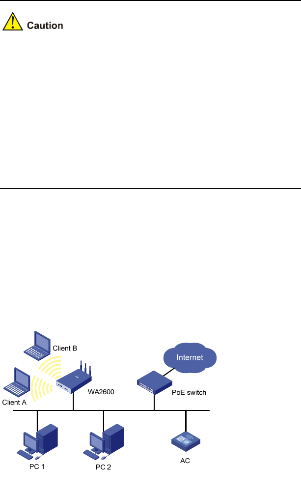
Figure 1-1 shows a typical scenario of hotspot deployments using the
WA2600 series.
Figure 1-1 Typical networking using the WA2600 series
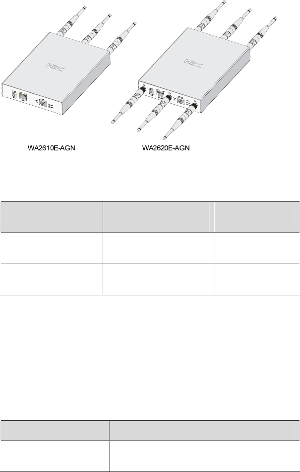
Figure 1-2 shows the appearance of the WA2600 series.
1-2
Figure 1-2 Appearance of the WA2600 series
Table 1-1 Physical dimensions and weight of the WA2600 series
Model Physical dimensions
(H×W×D) Weight
H3C
WA2610E-AGN 35 × 210 × 150 mm
(1.38 × 8.27 × 5.91 in.) 1.2 kg (2.65 lb.)
H3C
WA2620E-AGN 35 × 210 × 150 mm
(1.38 × 8.27 × 5.91 in.) 1.3 kg (2.87 lb.)
Hardware Configuration
The two models of the WA2600 series have different radio
frequencies (RFs) and structures. Table 1-2 lists the supported
protocols and the chassis material.
Table 1-2 Supported protocols and chassis material
Model Protocols and chassis material
H3C WA2610E-AGN IEEE 802.11a/b/g/n, single-RF, sheet
metal
1-3
Model Protocols and chassis material
H3C WA2620E-AGN IEEE 802.11a/b/g/n, dual-RF, sheet
metal
The following describes the hardware configurations and functions of
the WA2600 series in detail.
LEDs
The positions and identifications of LEDs on the panel vary with the
models. For details about these LEDs, see Table 1-3.
H3C WA2610E-AGN
Figure 1-3 LEDs on the H3C WA2610E-AGN
H3C WA2620E-AGN
Figure 1-4 LEDs on the H3C WA2620E-AGN

1-4
Table 1-3 Description of the LEDs on the WA2610E-AGN and
WA2620E-AGN
LED Color QTY Meaning
POWER Green 1
Displays the power supply status:
z On: The power supply is
normal.
z Off/blinking: The power supply
is not well connected or works
abnormally.
RADIO Green 1
Displays the wireless link status:
z On: The wireless link is normal.
z Off: The wireless link is not
initialized or the link is faulty.
z Blinking slowly: The wireless
link works normally.
z Blinking rapidly: Data is being
transmitted or received.
2.4GHz
(Wireless
link LED)
Green 1
Displays the 2.4 GHz wireless link
status:
z On: The wireless link is normal.
z Off: The wireless link is not
initialized or the link is faulty.
z Blinking slowly: The wireless
link works normally.
z Blinking rapidly: Data is being
transmitted or received.
5GHz
(Wireless
link LED)
Green 1
Displays the 5 GHz wireless link
status:
z On: The wireless link is normal.
z Off: The wireless link is not
initialized or the link is faulty.
z Blinking slowly: The wireless
link works normally.
z Blinking rapidly: Data is being
transmitted or received.

1-5
LED Color QTY Meaning
10/100M
(Ethernet
interface
LED)
Yellow 1
Displays the status of the Ethernet
interface:
z On: The Ethernet interface is in
the link-up state.
z Off: The Ethernet interface is in
the link-down state.
z Blinking: Data is being
transmitted or received at
10/100 Mbps.
1000M
(Ethernet
interface
LED)
Green 1
Displays the status of the 1000 M
Ethernet interface:
z On: The Ethernet interface is in
the link-up state.
z Off: The Ethernet interface is in
the link-down state.
z Blinking: Data is being
transmitted or received at 1000
Mbps.
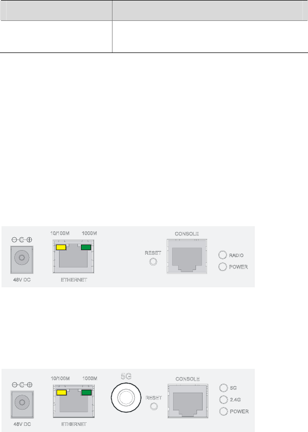
Interfaces
The WA2600 series provide the following interfaces:
z 2.4 GHz or 5 GHz antenna interfaces
z A console interface
z An Ethernet copper interface
z A power supply interface
1-6
In addition, the WA2600 series have a reset button and a security
slot.
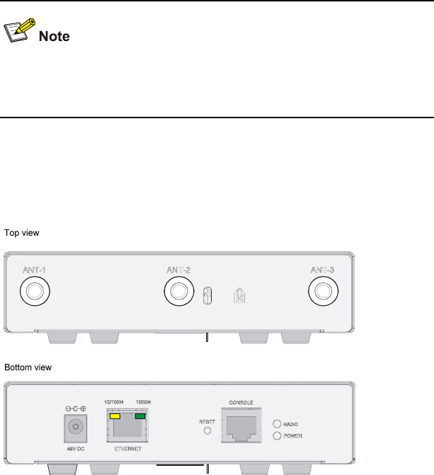
Interfaces provided by the H3C WA2610E-AGN
Figure 1-5 Interfaces on the H3C WA2610E-AGN

1-8
Table 1-4 Descriptions of interfaces on the WA2600 series WLAN
access points
Model Interface Standards
and
protocols Description
ANT-1
ANT-2
ANT-3
IEEE802.11
a
IEEE802.11
b
IEEE802.11
g
IEEE802.11
n
The antenna interfaces
are provided for 2.4
GHz/5 GHz dual-RF
antennas for MIMO
transmission.
Console RS/EIA-232
The console interface is
used for device
configuration and
management.
Ethernet
IEEE802.3
IEEE802.3u
IEEE802.3af
The Ethernet interface
can serve as an uplink
interface to access the
Internet or MAN, and as a
PoE interface at the same
time.
WA2610
E-AGN
Power
supply —
The power supply
interface is used for +48
VDC power supply to the
device.

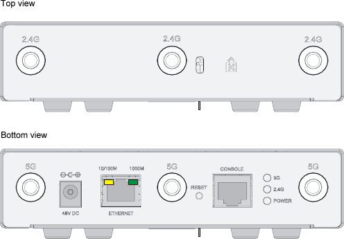
1-9
Model Interface Standards
and
protocols Description
Antenna
interface
(2.4 G)
IEEE802.11
b
IEEE802.11
g
IEEE802.11
n
This antenna interface is
used to connect a 2.4
GHz antenna or a feeder.
Antenna
interface
(5 G)
IEEE802.11
a
IEEE802.11
n
This antenna interface is
used to connect a 5 GHz
antenna or a feeder.
Console RS/EIA-232
The console interface is
used for device
configuration and
management.
Ethernet
IEEE802.3
IEEE802.3u
IEEE802.3af
The Ethernet interface
can serve as an uplink
interface to access the
Internet or MAN, and a
PoE interface at the same
time, supporting
non-standard PoE power
supply.
WA2620
E-AGN
Power
supply —
The power supply
interface is used for +48
VDC power supply to the
device.

2-1
2 Preparing for Installation
This chapter describes the preparations for WA2600 installation,
including the preparation of installation tools, environment
examination, unpacking and inspection.
Unpacking and Inspection
Before unpacking the package, make sure that the package is intact,
without any serious damage or signs of water soaking. When
unpacking the package, avoid excessive force or collision. Otherwise,
the articles inside the package may get damaged.
After unpacking the package, make sure that the following articles are
available in the package:
Table 2-1 List of articles in the package
Description QTY
WA2600 WLAN AP 1 PCS
Power adapter 1 PCS
220 VAC power cord 1 PCS
Console cable 1 PCS
Installation kit 1 set
Omni antennas 3/6 PCS
H3C WA2600 Series WLAN Access Points
Installation Manual 1 PCS
Packing list 1 PCS

2-2
z The accessories may vary with the models. For the exact
contents of the package, refer to the packing list.
z If the contents do not check with the packing list, timely contact
your local dealer.
z If the package is found to be rusted or water soaked, stop
unpacking and contact your local dealer immediately.
z Three omni antennas are shipped with the WA2610E-AGN, while
six omni antennas are shipped with the WA2620E-AGN.
Preparing Installation Tools
When installing the AP, you may need the tools listed in Table 2-2.
Choose the appropriate tools according to the installation
environment.
Table 2-2 List of installation tools
Type of tool Indoor installation
General tools 1-meter-long rulers, marking pens, knives,
and a percussion drill with appropriate bits
Special tools Cable strippers, crimping pliers, and RJ-45
crimping pliers
Auxiliary tools Ladders and rubber hammers

2-3
Table 2-2 is for reference only. If you install the AP on a tabletop,
none of the above tools is required.
Examining the Installation Site
Before installation, examine the installation site to make sure that the
AP will work in a good environment. You can examine the installation
site from the following two aspects.
Installation Site Selection
Keep the AP away from high temperature, dust, harmful gases,
inflammables, explosive substances, electromagnetic interference
sources (heavy-duty radars, radio stations, or electrical substations),
unstable voltage, heavy vibration, or loud noise. The installation site
should be dry, without any leakage, dripping or dew. The AP should
be at least 500 m (0.31 miles) away from the seaside and should not
face the direction of sea wind.
In engineering design, the site should be selected according to the
network planning and technical requirements of the communications
equipment, and the considerations such as climate, hydrology,
geology, earthquake, electric power, and transportation.
Temperature and Humidity Requirements
Table 2-3 lists the operating temperature and humidity requirements.
Table 2-3 Environment specifications
Specification Range
Operating temperature (indoor) 0°C to 45°C (32°F to 113°F)

2-4
Specification Range
Storage temperature –40°C to +70°C (–40°F to
+158°F)
Relative humidity
(noncondensing) 10% to 95%
Power Supply
Check that the power supply of the installation site is stable. The
centralized AC power system consisting of the AC mains, UPS, and
user-supplied diesel generator should be:
z Easy to connect
z Safe to operate
z Flexible to dispatch
z Convenient to maintain
The low-voltage power supply should adopt the single-phase
three-wire system. Table 2-4 lists the nominal voltage and frequency
of the low-voltage AC power supply.
Table 2-4 Nominal voltage and frequency of the low-voltage AC
power supply
Power supply Nominal voltage Stable frequency
Single-phase
three-wire (V) 100 VAC to 240
VAC 50/60 Hz

2-5
z If the voltage is unstable, a voltage regulator or stabilizer is
required.
z An uninterrupted power supply (UPS) is required for
uninterrupted communication.
Grounding and Lightning Protection
Table 2-5 Grounding and lightning protection requirements
Item Requirements
Grounding
resistance
z The grounding resistance is typically required to
be less than 5 ohms, and less than 10 ohms in an
area that has less than 20 thunderstorm days a
year. If an angle iron is to be buried into the earth
as the earthing conductor, the grounding
resistance is required to be less than 10 ohms. If
the installation site has a high earth resistance
rate, it is recommended to spray some salt water
or resistance-reducing agent on the earth around
the buried earthing conductor to reduce the
resistance rate of the earth.
z The top of the earthing conductor should be at
least 0.7 m (2.30 ft) away from the ground
surface. In cold areas, the earthing conductor
should be buried below the frozen soil layer.

2-6
Item Requirements
Protection
grounding
z If a grounding strip is available at the site, attach
the yellow-green PGND cable of the AP to the
grounding strip. The PGND cable must have a
cross-section area of at least 6 mm2 (0.01 in2)
and a length not longer than 3 m (9.84 ft).
z If no grounding strip is available at the site,
hammer a 0.5 m (1.64 ft) or longer angle iron or
steel tube into the earth. The angle iron should be
sized at least 50 × 50 × 5 mm (1.97 × 1.97 × 0.20
in.); the steel tube should have a wall thickness of
at least than 3.5 mm (0.18 in.) and be zinc-plated.
Weld the yellow-green grounding cable to the
angel iron or steel tube and treat the joint for
corrosion protection. With a cross-section area of
at least 6 mm2 (0.01 in2), the grounding cable
should be as short as possible. Do not coil the
cable.
z Make sure the lightning arresters of all devices
and the peering devices connected to these
devices are well grounded.
Grounding
lead
The grounding lead is a metal conductor connecting
the grounding strip to the grounding grid. The PGND
cable of the device should be attached to the
grounding strip. The grounding lead should not be
longer than 30 m (98.43 ft). A zinc-plated flat steel
with a cross-section area of 40 × 4 mm (1.57 × 0.16
in) or 50 × 5 mm (1.97 × 0.20 in) is recommended.
The grounding strip and the grounding lead should
be jointed using a 35 mm2 yellow-green PGND
cable or directly welded together with the joint
treated for corrosion protection.
AC power
grounding
z Make sure you use the power cable with a PE
terminal but not the cables with only L and N
wires.
z It is strictly prohibited to connect the N wire of the
power cable to the protection ground of any other
communications device, and the L and N wires
must be connected correctly.

2-7
Item Requirements
Lightning
rod
In a plain area, the protection angel of the lightning
rod should be less than 45 degrees. In a
mountainous area or lightning intensified area, the
protection angle should be less than 30 degrees.
The lightning protection ground (for example, the
ground of the lightning rod) and the protection
ground of the equipment room should be connected
to the same earthing conductor.
Feeder
z The antenna support is ready and in accordance
with the design requirement.
z A feeder lightning rod is already installed and
grounded according to the design requirement.
Outdoor
lightning
arresters
In case of outdoor installation, a power supply
lightning arrester, a feeder lightning arrester and a
network port lightning arrester are required. The
power supply lightning arrester and feeder lightning
arrester are located close to the AP while the
network port lightning arrester is installed close to
the peer device where the network cable goes out of
the room.
Network
cable
In case of outdoor installation, make sure to use a
shielded network cable and the interconnected
devices are well grounded.
After you have completed the preparations, you can start installing the
AP. For details, refer to 3 "Installing the AP" on page 3-1.
3-1
3 Installing the AP
The WA2600 series WLAN APs can be directly fixed onto a wall by
using the wall-mounting brackets. The following introduces the
wall-mounting procedure of the WA2600 series in detail.
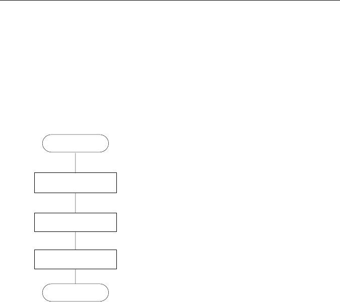
Installation Flowchart
Figure 3-1 shows the installation flowchart of the WA2600 series.
Figure 3-1 Installation flowchart
End
Determine the
installation position
Install the AP
Connect the power
supply and the network
Start
Determining the Installation Position
Determine the installation position by observing the following
principles:
z Leave as few obstacles (such as wall and ceiling) as possible
between the AP and the wireless stations.

3-2
z Keep the AP far away from electronic devices (such as
microwave ovens) that may generate RF noise.
z Install the AP in a place where it will not hinder people’s daily
work and life.
Make sure the ceiling is strong enough and the structure is suitable in
case of ceiling mounting. Reinforce the ceiling if needed. A padlock is
required for ceiling mounting to prevent any falloff in case of shocks.
A Blossom 071 padlock or similar padlock is recommended.
Installing the AP on a Wall
The following describes how to install a WA2600 series AP on a wall:
z Installing the Wall-Mounting Bracket on the Wall
z Installing the AP on the Wall-Mounting Bracket
z Locking the AP onto the Wall-Mounting Bracket (Optional)
Installing the Wall-Mounting Bracket on the Wall
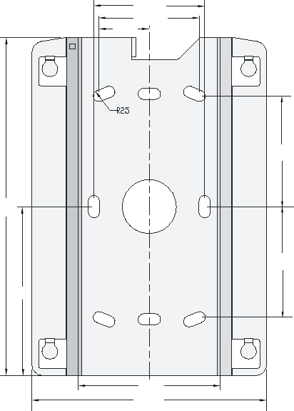
1) Drill holes 6 mm (0.24 in) in diameter on the wall where the AP is to
be mounted. The drilled holes must correspond to those in the
wall-mounting bracket. There are eight installation holes in total in
the wall-mounting bracket. Select at least four of them for the
installation.
3-3
Figure 3-2 Screw hole locations and screw hole size
49.0
44.6
22.3
49.1
49.1
150.0
75.0
62.9
104.0
2) Insert the pointed end of anchors into the drilled holes and tap the
flat end of anchors with a rubber hammer until they are all flush
with the wall surface.
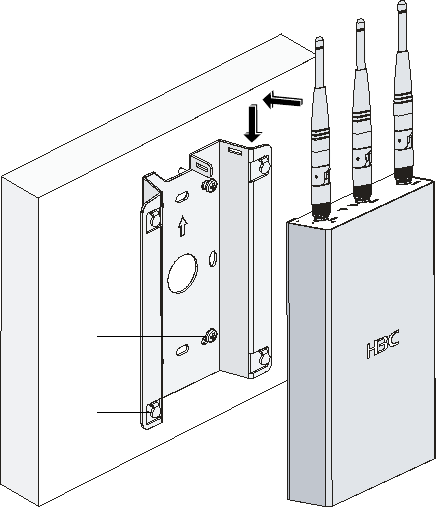
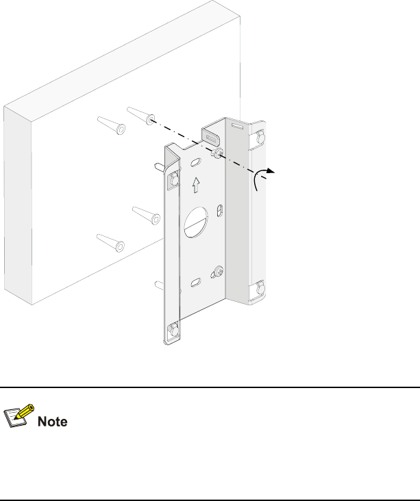
3) Align the holes in the wall-mounting bracket with the anchors and
insert screws through the installation holes into the anchors, as
shown in Figure 3-3.
4) Adjust the position of the wall-mounting bracket and tighten the
screws.

3-4
Figure 3-3 Install the wall-mounting bracket
Install the wall-mounting bracket with the arrow on the bracket
pointing upwards.

3-5
Installing the AP on the Wall-Mounting Bracket
The installation procedure is the same for both the WA2610E-AGN
and WA2620E-AGN. The WA2610E-AGN is taken as an example in
this manual.
1) Align the AP with the hooks on the wall-mounting bracket and
hang the AP on the bracket. See (1) in Figure 3-4.
2) Press the AP downward to fix it. See (2) in Figure 3-4.
3-6
Figure 3-4 Fix the AP onto the wall-mounting bracket
Expansion
screw
Hook
(1)
(2)
Locking the AP onto the Wall-Mounting Bracket (Optional)
The WA2600 series APs have a security slot on the top, which can be
used to lock the AP onto the wall-mounting bracket to prevent theft.
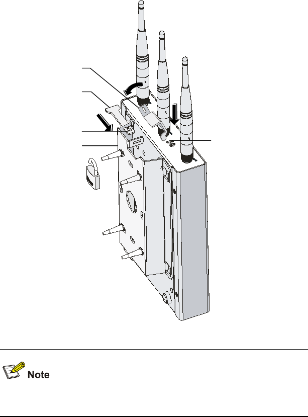
Follow these steps to lock the AP onto the wall-mounting bracket:
1) Insert the locking plate into the security slot on the top of the AP.
See (1) in Figure 3-5.
2) Turn the locking plate counterclockwise until the hole on the
locking plate is aligned with the hole in the wall-mounting bracket.
See (2) in Figure 3-5.
3) Put the latch through the two holes that are aligned in step 2. See
(3) in Figure 3-5.
4) Lock the latch with a lock.
3-7
Figure 3-5 Lock the AP onto the wall-mounting bracket
Locking plate
Latch (1)
(2)
Locking hole
Wall-mounting bracket
(3)
Security slot
The lock is user supplied.
3-8
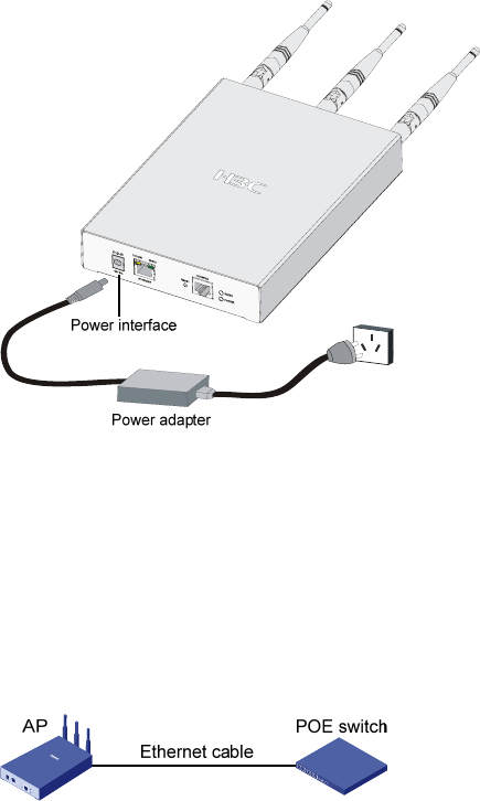
Connecting the Power Supply
Local Power Supply
Connect the AP to the power source through the power adapter, as
shown in Figure 3-6.
Figure 3-6 Local power supply connection
Power over Ethernet
If the uplink device of the AP is a PoE-capable switch or the like, use
an Ethernet cable to connect the Ethernet interface of the AP to the
PoE-capable device.
Figure 3-7 PoE connection

3-9
z In the PoE mode, you do not need to connect the power interface
to a power source. You only need to connect one end of an
Ethernet cable to the Ethernet interface of the AP and the other
end to an Ethernet interface of the PoE-capable device (for
example, an Ethernet switch).
z Identify the silkscreen on the device to avoid taking the console
interface for the Ethernet interface, or vice versa.
z The WA2620E-AGN supports only non-standard PoE power
supply.
Connecting the AP to the Network
The WA2600 series can access the Internet or MAN through the
Ethernet uplink interface. Connect the Ethernet interface of the AP to
an Ethernet interface of an Ethernet switch to implement Internet or
MAN access, as shown in Figure 3-8.
Figure 3-8 Connect the AP to the network
i
Table of Contents
1 Regulatory Compliance Information...................................................1-1
Regulatory compliance standards......................................................1-1
Support Antennas & Accessories information....................................1-1
EU Compliance information ...............................................................1-3
CE Marking.................................................................................1-3
EU Country Restriction in 2.4GHz band.....................................1-6
EU Country Restriction in 5GHz band........................................1-6
WEEE Directive–2002/96/EC.....................................................1-7
USA Compliance information.............................................................1-8
US Federal Communications Commission statement................1-8
RF Requirements........................................................................1-8
Antennas.....................................................................................1-9
WLAN Module.............................................................................1-9
Industry Canada.................................................................................1-9
RF Compliance...........................................................................1-9
Brazil RF Compliance ......................................................................1-10
Korea RF Compliance......................................................................1-11
Taiwan regulatory statement............................................................1-12
2 Safety Information Sicherheitsinformationen....................................2-1
General Requirements Allgemeine Anforderungen ...........................2-1
Electricity Safety Elektrische Sicherheit.............................................2-2

1-1
1 Regulatory Compliance Information
Regulatory compliance standards
Table 1-1 Regulatory compliance standards
Discipline Standards
EMC & RF
FCC Part 15.207 & 15.209 & 15.247& 15.205 &
15.407
FCC Bulletin OET-65C
IC RSS 210
ETSI EN 300 328
ETSI EN 301 893
EN 60601-1-2
EN 61000-3-2
EN 61000-3-3
ETSI EN 301 489-1
ETSI EN 301 489-17
Safety
UL 60950-1
CAN/CSA C22.2 No 60950-1
IEC 60950-1
EN 60950-1
Support Antennas & Accessories information
This product can be used with the following antennas and
accessories:
Table 1-2 Authorized Antennas & Accessories
Item Description Exclusions
Supplied Antenna None
C5060-510002-A 3Com 2/8dBi Dual-Band
Omni Antenna None

1-2
Item Description Exclusions
3CWE591 3Com 6/8dBi Dual-Band
Omni Antenna
Must be used with 3CWE586
and one of the following:
3CWE580,
3CWE581 or 3CWE582.
3CWE596
3Com 18/20dBi
Dual-Band Panel
Antenna
Must be used with 3CWE586
and one of the following:
3CWE580,
3CWE581 or 3CWE582.
3CWE598
3Com 8/10dBi
Dual-Band Panel
Antenna Product
Must be used with 3CWE586
and one of the following:
3CWE580,
3CWE581 or 3CWE582.
TQJ-24/58MICX6
2.5dBi/4.5dBi
Dual-Band MIMO
Antenna
Depend on availability.
TQJ-2458MIKX3 2.5dBi/4dBi Dual-Band
MIMO Antenna Depend on availability.
MCM2458PTRPS
M
3dBi/4dBi Dual-Band
MIMO Antenna Depend on availability.
3CWE580 3Com Ultra Low Loss
6-Foot Antenna Cable Must also use 3CWE586.
3CWE581 3Com Ultra Low Loss
20-Foot Antenna Cable Must also use 3CWE586.
3CWE582 3Com Ultra Low Loss
50-Foot Antenna Cable Must also use 3CWE586.
3CWE586 3Com RSMA to SMA 6-
inch Antenna Cable
Required for all external
antennas
(not required for 3CWE590
Antenna).
z This product does not contain any user serviceable components.
Any unauthorized product changes or modifications will
invalidate the warranty and all applicable regulatory certifications
and approvals.
z This product must be installed by a professional technician/
installer.

1-3
EU Compliance information
CE Marking
Equipment may be operated in the following country:
AT BE CY CZ DK EE FI FR
DE GR HU IE IT LV LT LU
MT NL PL PT SK SI ES SE
GB IS LI NO CH BG RO TR
1) Select the country in which the product is installed to ensure
product operation is in compliance with local regulations. For
information on how to select the country, refer to the “Wireless
Configuration Command” module in H3C Wireless Control
Manager Command Manual.
2) Intended use: IEEE 802.11a/b/g and 802.11n Draft 2.0.
3) This product must maintain a minimum body to antenna distance
of 20cm.Under these conditions this product will meet the Basic
Restriction limits of 1999/519/EC(Council Recommendation of 12
July 1999 on the limitation of exposure of the general public to
electromagnetic fields(0Hz-300GHz).
R&TTE declaration statements:
Česky [Czech]
H3C Coporation tímto prohlašuje, že tento RLAN device
je ve shodě se základními požadavky a dalšími
příslušnými ustanoveními směrnice 1999/5/ES.
Dansk
[Danish]
Undertegnede H3C Corporation erklærer herved, at
følgende udstyr RLAN device overholder de væsentlige
krav og øvrige relevante krav i direktiv 1999/5/EF.

1-4
Deutsch
[German]
Hiermit erklärt H3C Corporation, dass sich das Gerät
RLAN device in Übereinstimmung mit den
grundlegenden Anforderungen und den übrigen
einschlägigen Bestimmungen der Richtlinie 1999/5/EG
befindet.
Eesti
[Estonian]
Käesolevaga kinnitab H3C Corporation seadme RLAN
device vastavust direktiivi 1999/5/EÜ põhinõuetele ja
nimetatud direktiivist tulenevatele teistele asjakohastele
sätetele.
English
Hereby, H3C Corporation, declares that this RLAN
device is in compliance with the essential requirements
and other relevant provisions of Directive 1999/5/EC.
Español
[Spanish]
Por medio de la presente H3C Corporation declara que
el RLAN device cumple con los requisitos esenciales y
cualesquiera otras disposiciones aplicables o exigibles
de la Directiva 1999/5/CE.
Ελληνική
[Greek]
ΜΕ ΤΗΝ ΠΑΡΟΥΣΑ H3C Corporation ΔΗΛΩΝΕΙ ΟΤΙ
RLAN device ΣΥΜΜΟΡΦΩΝΕΤΑΙ ΠΡΟΣ ΤΙΣ
ΟΥΣΙΩΔΕΙΣ ΑΠΑΙΤΗΣΕΙΣ ΚΑΙ ΤΙΣ ΛΟΙΠΕΣ ΣΧΕΤΙΚΕΣ
ΔΙΑΤΑΞΕΙΣ ΤΗΣ ΟΔΗΓΙΑΣ 1999/5/ΕΚ.
Français
[French]
Par la présente H3C Corporation déclare que l'appareil
RLAN device est conforme aux exigences essentielles
et aux autres dispositions pertinentes de la directive
1999/5/CE.
Italiano
[Italian]
Con la presente H3C Corporation dichiara che questo
RLAN device è conforme ai requisiti essenziali ed alle
altre disposizioni pertinenti stabilite dalla direttiva
1999/5/CE.
Latviski
[Latvian]
Ar šo H3C Corporation deklarē, ka RLAN device atbilst
Direktīvas 1999/5/EK būtiskajām prasībām un citiem ar
to saistītajiem noteikumiem.
Lietuvių
[Lithuanian]
Šiuo H3C Corporation deklaruoja, kad šis RLAN device
atitinka esminius reikalavimus ir kitas 1999/5/EB
Direktyvos nuostatas.
Nederlands
[Dutch]
Hierbij verklaart H3C Corporation dat het toestel RLAN
device in overeenstemming is met de essentiële eisen
en de andere relevante bepalingen van richtlijn
1999/5/EG.
Malti [Maltese]
Hawnhekk, H3C Corporation, jiddikjara li dan RLAN
device jikkonforma mal-ħtiġijiet essenzjali u ma
provvedimenti oħrajn relevanti li hemm fid-Dirrettiva
1999/5/EC.

1-5
Magyar
[Hungarian]
Alulírott, H3C Corporation nyilatkozom, hogy a RLAN
device megfelel a vonatkozó alapvetõ
követelményeknek és az 1999/5/EC irányelv egyéb
elõírásainak.
Polski [Polish]
Niniejszym H3C Corporation oświadcza, że RLAN
device jest zgodny z zasadniczymi wymogami oraz
pozostałymi stosownymi postanowieniami Dyrektywy
1999/5/EC.
Português
[Portuguese]
H3C Corporation declara que este RLAN device está
conforme com os requisitos essenciais e outras
disposições da Directiva 1999/5/CE.
Slovensko
[Slovenian]
H3C Corporation izjavlja, da je ta RLAN device v skladu
z bistvenimi zahtevami in ostalimi relevantnimi določili
direktive 1999/5/ES.
Slovensky
[Slovak]
H3C Corporation týmto vyhlasuje, že RLAN device
spĺňa základné požiadavky a všetky príslušné
ustanovenia Smernice 1999/5/ES.
Suomi
[Finnish]
H3C Corporation vakuuttaa täten että RLAN device
tyyppinen laite on direktiivin 1999/5/EY oleellisten
vaatimusten ja sitä koskevien direktiivin muiden ehtojen
mukainen.
Svenska
[Swedish]
Härmed intygar H3C Corporation att denna RLAN
device står I överensstämmelse med de väsentliga
egenskapskrav och övriga relevanta bestämmelser som
framgår av direktiv 1999/5/EG.
Íslenska
[Icelandic]
Hér með lýsir H3C Corporation yfir því að RLAN device
er í samræmi við grunnkröfur og aðrar kröfur, sem
gerðar eru í tilskipun 1999/5/EC.
Norsk
[Norwegian]
H3C Corporation erklærer herved at utstyret RLAN
device er i samsvar med de grunnleggende krav og
øvrige relevante krav i direktiv 1999/5/EF.
A copy of the signed Declaration of Conformity can be downloaded
from:
http://www.h3c.com/portal/Technical_Documents
http://support.3com.com/doc/H3C_WA26XXE-AGN_EU_DOC.pdf
1-6
Table 1-3 Overview of Regulatory Requirements for Wireless LANs
Frequency
Band (MHz) Max Power
Level (EIRP) (mW)
Indoor ONLY Indoor and
Outdoor
2400 – 2483.5 100 mW X
5150 – 5250 50 mW X
5250 – 5350 200 mW X
5470 – 5725 1000 mW X
Dynamic Frequency Selection and Transmit Power Control is
required in the 5250- to 5350-MHz and 5470- to 5725-MHz frequency
range.
EU Country Restriction in 2.4GHz band
This device may be used indoors or outdoors in all countries of the
European Community using the 2.4GHz band: Channel 1-13, except
where noted below.
1) In France, the output power is restricted to 10 mW EIRP when the
product is used outdoors in the band 2454 - 2483.5 MHz. There
are no restrictions when used in other parts of the 2.4 GHz band.
EU Country Restriction in 5GHz band
1) In Italy the end-user must apply for a license from the national
spectrum authority to operate this device outdoors.
2) To remain in conformance with European spectrum usage laws for
Wireless LAN operation, the above 2.4GHz and 5GHz channel
limitations apply. The user should check the current channel of
operation. If operation is occurring outside of the allowable
frequencies as listed above, the user must cease operating the

1-7
WA2600 series at that location and consult the local technical
support staff responsible for the wireless network.
3) This device must be used with the radar detection feature required
for European Community operation in the 5GHz bands. This
device will avoid operating on a channel occupied by any radar
system in the area. The presence of nearby radar operation may
result in temporary interruption in communications of this device.
The Access Point’s radar detection feature will automatically
restart operation on a channel free of radar. You may consult with
the local technical support staff responsible for the wireless
network to ensure the Access Point device(s) are properly
configured for European Community operation.
Europe-Restrictions for Use of 5GHz Frequencies in European
Community Countries
Allowed
Frenquecy
Bands
Allowed
Channel
Numbers Countries
5.15-5.35&
5.470-5.725G
Hz
36,38,40,44,4
6,48,52,54,56,
60,62,64,100,
102,104,108,1
10,112,116,11
8,120,124,126
,128,132,134,
136,140
Austria, Belgium, Bulgaria, Cyprus,
Czech Republic, Denmark, Estonia,
Finland, France, Germany, Greece,
Hungary, Iceland, Ireland, Italy, Latvia,
Liechtenstein, Lithuania, Luxembourg,
Malta, Netherlands, Norway, Poland,
Portugal, Slovakia, Slovenia, Spain,
Sweden, Switzerland, U.K.
WEEE Directive–2002/96/EC
1-8
The products this manual refers to are covered by the Waste
Electrical & Electronic Equipment (WEEE) Directive and must be
disposed of in a responsible manner.
USA Compliance information
US Federal Communications Commission statement
This device complies with Part 15 of the FCC Rules. Operation is
subject to the following two conditions:
z This device may not cause harmful interference.
z This device must accept any interference received, including
interference that may cause undesired operation.
RF Requirements
RF exposure Hazard Warning
This device generates and radiates radio-frequency energy. In order
to comply with FCC radio-frequency exposure guidelines for an
uncontrolled environment, this equipment must be installed and
operated while maintaining a minimum body to antenna distance of
20 cm (approximately 8 in.)
Note: Minimum distance 40cm is required when 3CWE596
antenna is used.
RF Frequency Requirements
This equipment complies with FCC RF radiation exposure limits set
forth for an uncontrolled environment. This device and its antenna
must not be co-located or operating in conjunction with any other
unauthorized antenna or transmitter.
This device is for indoor use only when using all channels in the 5.15
to 5.25 GHz, 5.47 to 5.6GHz or 5.65 to 5.725GHz frequency range.
High power radars are allocated as primary users of the 5.25 to 5.35
GHz and -5.47 to 5.6 GHz and 5.65 to 5.725 GHz bands.
1-9
These radar stations can cause interference with and/or damage this
device.
This device will not operations on channels which overlap the
5600 - 5650 MHz band
USA Restriction in 2.4GHz band
This device may be used in USA using the 2.4GHz band: Channel
1-11.
Antennas
Only use the supplied antenna. Unauthorized antennas,
modifications or change to the antennas could violate FCC
regulations and void the user’s authority to operate the equipment.
Industry Canada
RF Compliance
This Class B digital apparatus complies with Canadian ICES-003.
Cet appareil numérique de la classe B est conform à la norme
NMB-003 du Canada.
This device complies with RSS 210 of Industry Canada.
Operation is subject to the following two conditions: (1) this device
may not cause interference, and (2) this device must accept any
interference, including interference that may cause undesired
operation of this device.
L ‘ utilisation de ce dispositif est autorisée seulement aux conditions
suivantes: (1) il ne doit pas produire de brouillage et (2) l’ utilisateur du
dispositif doit étre prêt à accepter tout brouillage radioélectrique reçu,
même si ce brouillage est susceptible de compromettre le
fonctionnement du dispositif.
The term "IC" before the equipment certification number only signifies
that the Industry Canada technical specifications were met.
1-10
To reduce potential radio interference to other users, the antenna type
and its gain should be so chosen that the equivalent isotropically
radiated power (EIRP) is not more than that required for successful
communication. To prevent radio interference to the licensed service,
this device is intended to be operated indoors and away from
windows to provide maximum shielding. Equipment (or its transmit
antenna) that is installed outdoors is subject to licensing.
Pour empecher que cet appareil cause du brouillage au service
faisant l'objet d'une licence, il doit etre utilize a l'interieur et devrait
etre place loin des fenetres afin de Fournier un ecram de blindage
maximal. Si le matriel (ou son antenne d'emission) est installe a
l'exterieur, il doit faire l'objet d'une licence.
This device is for indoor use only when using channels 36, 38, 40, 42,
44, 46 or 48 in the 5.15 to 5.25 GHz frequency range.
High power radars are allocated as primary users of the 5.25 to 5.35
GHz and -5.47 to 5.6 GHz and 5.65 to 5.725GHz bands.
These radar stations can cause interference with and/or damage this
device.
This device will not operations on channels which overlap the
5600 - 5650 MHz band
This device must not be co-located or operated in conjunction with
any other unauthorized antenna or transmitter.
RF exposure Hazard Warning
Minimum distance 40cm is required when 3CWE596 antenna is used.
Brazil RF Compliance
Este produto está homologado pela ANATEL, de acordo com os
procedimentos regulamentados pela Resolução 242/2000 e atende
aos requisitos técnicos aplicados.

1-11
Este equipamento opera em caráter secundário, isto é, não tem
direito a proteção contra interferência prejudicial, mesmo de
estações do mesmo tipo, e não pode causar interferência a sistemas
operando em caráter primário.
Para maiores informações, consulte o site da ANATEL –
www.anatel.gov.br
Korea RF Compliance
This device may cause radio interference during its operation.
Therefore service in relation to human life security is not available.
1-12
Taiwan regulatory statement
1) 經審驗合格之射頻電信終端設備,非經許可,公司商號或使用者均
不得擅自變更頻率,加大功率或功率或變更原設計之特性及功能。
2) 射頻電信終端設備之使用不得影響飛航安全及干擾合法通信;經發
現有干擾現象時,應立即停用,並改善至無干擾時方得繼續使用。
所謂合法通信,係指依電信法規定作業之無線電信。
3) 輸入、製造射頻電信終端設備之公司、商號或其使用者違反本辦法
規定,擅自使用或變更無線電頻率、電功率者,除依電信法規定處
罰外,電信總局並得撤銷其審驗合格證明。
4) 本機限在不干擾合法電台與不受被干擾保障條件下於室內使用。
5) 在5.25-5.35 秭赫頻帶內操作之無線資訊傳輸設備,限於室內使用。
6) 無線資訊傳輸設備的製造廠商應確保頻率穩定性,如依製造廠商使
用手冊上所述正常操作,發射的信號應維持於操作頻帶中。
7) 為減少電磁波干擾,請妥適使用。

2-1
2 Safety Information
Sicherheitsinformationen
General Requirements Allgemeine Anforderungen
In order to reduce the technically unavoidable residual risk to a
minimum, it is imperative to follow the rules below:
Um das technisch bedingte Restrisiko auf ein Minimum zu begrenzen,
ist es unbedingt erforderlich, die folgenden Regeln zu beachten:
z Read all the instructions before operation.
z Lesen Sie alle Anweisungen sorgfältig durch, bevor Sie mit dem
Arbeiten beginnen.
z Do not block ventilation openings while the system is on, and
keep at least 5 cm distance from ventilation openings and walls
or other things which may block the openings.
z Sorgen Sie dafür, dass die Öffnungen der Ventilation zu keinem
Zeitpunkt verschlossen, verstopft oder anderweitig blockiert sind.
Zwischen den Ventilationsöffnungen und Wänden bzw. anderen
Gegenständen muss stets ein Abstand von mindestens 5cm
bestehen.
z For AC supplied model: To ensure the safety of the equipment
and human body, please unplug the AC power connector and do
not use the fixed terminal in the lightning weather. Furthermore,
please do not touch the terminal or antenna connector in such
weather.
z Mit Wechselstrom betriebenes Modell: Um die Sicherheit des
Personals und der Ausrüstung zu gewährleisten, muss der
Stecker aus der Steckdose gezogen werden, wenn die Gefahr
eines Blitzeinschlages besteht. Verwenden Sie bei Blitzgefahr
2-2
keine festinstallierten Steckdosen. Berühren Sie bei Blitzgefahr
nicht die Antenne.
z To ensure the equipment mounted on the wall firmly, please use
nail at least 4.2mm diameter and the nail cap at least 8mm
diameter.
z Um die Sicherheit der Ausrüstung auf der Wand, der Nagel in
der Wand muss einen Durchmesser 4.2mm mindestens haben
und der Durchmesser von der Nagelkappe muss groesser als
8mm sein.
Electricity Safety Elektrische Sicherheit
z Conducting articles, such as watch, hand chain, bracelet and ring
are prohibited during the operation.
z Es ist nicht erlaubt während dieser Arbeiten leitende
Gegenstände wie Uhren, Armbänder, Armreifen und Ringe am
Körper zu tragen.
z When water is found in the rack, or the rack is damp, please
immediately switch off the power supply.
z Sollte sich Wasser im Baugruppenträger befinden oder der
Baugruppenträger feucht sein, ist die Energiezufuhr sofort zu
unterbrechen und das System abzuschalten.
z When operation is performed in a damp environment, make sure
that water is kept off the equipment.
z Muss in einem feuchten Umgebung gearbeitet werden, ist
sicherzustellen, dass kein Wasser in die Ausrüstung dringen
kann.
Users manual new

H3C WA2600 Series WLAN Access Points
Installation Manual
Hangzhou H3C Technologies Co., Ltd.
http://www.h3c.com
Manual Version: 5PW100-20081111

Copyright © 2008, Hangzhou H3C Technologies Co., Ltd. and its
licensors
All Rights Reserved
No part of this manual may be reproduced or transmitted in any form
or by any means without prior written consent of Hangzhou H3C
Technologies Co., Ltd.
Trademarks
H3C, , Aolynk, , H3Care,
, TOP G, ,
IRF, NetPilot, Neocean, NeoVTL, SecPro, SecPoint, SecEngine,
SecPath, Comware, Secware, Storware, NQA, VVG, V2G, VnG,
PSPT, XGbus, N-Bus, TiGem, InnoVision and HUASAN are
trademarks of Hangzhou H3C Technologies Co., Ltd.
All other trademarks that may be mentioned in this manual are the
property of their respective owners.
Notice
The information in this document is subject to change without notice.
Every effort has been made in the preparation of this document to
ensure accuracy of the contents, but all statements, information, and
recommendations in this document do not constitute the warranty of
any kind, express or implied.
Technical Support
customer_service@h3c.com
http://www.h3c.com
About This Manual
Organization
H3C WA2600 Series WLAN Access Points Installation Manual is
organized as follows:
Chapter Contents
1 Product Overview Introduces the hardware configurations,
appearance, and interfaces of the H3C
WA2600 Series WLAN Access Points.
2 Preparing for
Installation
Specifies the environmental requirements
for installing the H3C WA2600 Series
WLAN Access Points, presents installation
precautions, and introduces the installation
tools needed.
3 Installing the AP
Introduces how to install the H3C WA2600
Series WLAN Access Points and how to
connect the power supply units and the
Ethernet cable.
Conventions
The manual uses the following conventions:
Symbols
Convention Description
Means reader be extremely careful. Improper
operation may cause bodily injury.
Means reader be careful. Improper operation
may cause data loss or damage to equipment.

Convention Description
Means a complementary description.
Obtaining Documentation
You can access the most up-to-date H3C product documentation on
the World Wide Web at this URL: http://www.h3c.com.
The following are the columns from which you can obtain different
categories of product documentation:
[Products & Solutions]: Provides information about products and
technologies.
[Technical Support & Document > Technical Documents]: Provides
several categories of product documentation, such as installation,
operation, and maintenance.
Documentation Feedback
You can e-mail your comments about product documentation to
info@h3c.com.
We appreciate your comments.
Environmental Protection
This product has been designed to comply with the requirements on
environmental protection. For the proper storage, use and disposal of
this product, national laws and regulations must be observed.
i
Table of Contents
1 Product Overview .................................................................................1-1
Introduction.........................................................................................1-1
Hardware Configuration .....................................................................1-2
LEDs ...........................................................................................1-3
Interfaces....................................................................................1-5
2 Preparing for Installation .....................................................................2-1
Unpacking and Inspection..................................................................2-1
Preparing Installation Tools................................................................2-2
Examining the Installation Site...........................................................2-3
Installation Site Selection ...........................................................2-3
Temperature and Humidity Requirements .................................2-3
Power Supply..............................................................................2-4
Grounding and Lightning Protection...........................................2-5
3 Installing the AP....................................................................................3-1
Installation Flowchart .........................................................................3-1
Determining the Installation Position..................................................3-1
Installing the AP on a Wall .................................................................3-2
Installing the Wall-Mounting Bracket on the Wall.......................3-2
Installing the AP on the Wall-Mounting Bracket .........................3-5
Locking the AP onto the Wall-Mounting Bracket (Optional).......3-6
Connecting the Power Supply............................................................3-8
Local Power Supply....................................................................3-8
Power over Ethernet...................................................................3-8
Connecting the AP to the Network.....................................................3-9
ii
List of Figures
Figure 1-1 Typical networking using the WA2600 series ..................1-1
Figure 1-2 Appearance of the WA2600 series ..................................1-2
Figure 1-3 LEDs on the H3C WA2610E-AGN...................................1-3
Figure 1-4 LEDs on the H3C WA2620E-AGN...................................1-3
Figure 1-5 Interfaces on the H3C WA2610E-AGN............................1-6
Figure 1-6 Interfaces on the H3C WA2620E-AGN............................1-7
Figure 3-1 Installation flowchart ........................................................3-1
Figure 3-2 Screw hole locations and screw hole size .......................3-3
Figure 3-3 Install the wall-mounting bracket .....................................3-4
Figure 3-4 Fix the AP onto the wall-mounting bracket ......................3-6
Figure 3-5 Lock the AP onto the wall-mounting bracket....................3-7
Figure 3-6 Local power supply connection........................................3-8
Figure 3-7 PoE connection................................................................3-8
Figure 3-8 Connect the AP to the network ........................................3-9
iii
List of Tables
Table 1-1 Physical dimensions and weight of the WA2600 series ......1-2
Table 1-2 Supported protocols and chassis material.........................1-2
Table 1-3 Description of the LEDs on the WA2610E-AGN and
WA2620E-AGN...........................................................................1-4
Table 1-4 Descriptions of interfaces on the WA2600 series WLAN
access points..............................................................................1-8
Table 2-1 List of articles in the package ............................................2-1
Table 2-2 List of installation tools.......................................................2-2
Table 2-3 Environment specifications ................................................2-3
Table 2-4 Nominal voltage and frequency of the low-voltage AC power
supply .........................................................................................2-4
Table 2-5 Grounding and lightning protection requirements..............2-5
1-1
1 Product Overview
Introduction
The H3C WA2600 Series WLAN Access Points (hereinafter referred
to as the WA2600 series) are one of the 802.11n access point (AP)
product series developed by Hangzhou H3C Technologies Co., Ltd.
(hereinafter referred to as H3C). The WA2600 series can serve as FIT
APs to cooperate with wireless local area network (WLAN) switches
or access controllers to provide wireless access for WLAN users.
Figure 1-1 shows a typical scenario of hotspot deployments using the
WA2600 series.
Figure 1-1 Typical networking using the WA2600 series
Figure 1-2 shows the appearance of the WA2600 series.

1-2
Figure 1-2 Appearance of the WA2600 series
Table 1-1 Physical dimensions and weight of the WA2600 series
Model Physical dimensions
(H×W×D) Weight
H3C
WA2610E-AGN 35 × 210 × 150 mm
(1.38 × 8.27 × 5.91 in.) 1.2 kg (2.65 lb.)
H3C
WA2620E-AGN 35 × 210 × 150 mm
(1.38 × 8.27 × 5.91 in.) 1.3 kg (2.87 lb.)
Hardware Configuration
The two models of the WA2600 series have different radio
frequencies (RFs) and structures. Table 1-2 lists the supported
protocols and the chassis material.
Table 1-2 Supported protocols and chassis material
Model Protocols and chassis material
H3C WA2610E-AGN IEEE 802.11a/b/g/n, single-RF, sheet
metal

1-3
Model Protocols and chassis material
H3C WA2620E-AGN IEEE 802.11a/b/g/n, dual-RF, sheet
metal
The following describes the hardware configurations and functions of
the WA2600 series in detail.
LEDs
The positions and identifications of LEDs on the panel vary with the
models. For details about these LEDs, see Table 1-3.
H3C WA2610E-AGN
Figure 1-3 LEDs on the H3C WA2610E-AGN
H3C WA2620E-AGN
Figure 1-4 LEDs on the H3C WA2620E-AGN

1-4
Table 1-3 Description of the LEDs on the WA2610E-AGN and
WA2620E-AGN
LED Color QTY Meaning
POWER Green 1
Displays the power supply status:
z On: The power supply is
normal.
z Off/blinking: The power supply
is not well connected or works
abnormally.
RADIO Green 1
Displays the wireless link status:
z On: The wireless link is normal.
z Off: The wireless link is not
initialized or the link is faulty.
z Blinking slowly: The wireless
link works normally.
z Blinking rapidly: Data is being
transmitted or received.
2.4GHz
(Wireless
link LED)
Green 1
Displays the 2.4 GHz wireless link
status:
z On: The wireless link is normal.
z Off: The wireless link is not
initialized or the link is faulty.
z Blinking slowly: The wireless
link works normally.
z Blinking rapidly: Data is being
transmitted or received.
5GHz
(Wireless
link LED)
Green 1
Displays the 5 GHz wireless link
status:
z On: The wireless link is normal.
z Off: The wireless link is not
initialized or the link is faulty.
z Blinking slowly: The wireless
link works normally.
z Blinking rapidly: Data is being
transmitted or received.

1-5
LED Color QTY Meaning
10/100M
(Ethernet
interface
LED)
Yellow 1
Displays the status of the Ethernet
interface:
z On: The Ethernet interface is in
the link-up state.
z Off: The Ethernet interface is in
the link-down state.
z Blinking: Data is being
transmitted or received at
10/100 Mbps.
1000M
(Ethernet
interface
LED)
Green 1
Displays the status of the 1000 M
Ethernet interface:
z On: The Ethernet interface is in
the link-up state.
z Off: The Ethernet interface is in
the link-down state.
z Blinking: Data is being
transmitted or received at 1000
Mbps.
Interfaces
The WA2600 series provide the following interfaces:
z 2.4 GHz or 5 GHz antenna interfaces
z A console interface
z An Ethernet copper interface
z A power supply interface

1-6
In addition, the WA2600 series have a reset button and a security
slot.
Interfaces provided by the H3C WA2610E-AGN
Figure 1-5 Interfaces on the H3C WA2610E-AGN


1-8
Table 1-4 Descriptions of interfaces on the WA2600 series WLAN
access points
Model Interface Standards
and
protocols Description
ANT-1
ANT-2
ANT-3
IEEE802.11
a
IEEE802.11
b
IEEE802.11
g
IEEE802.11
n
The antenna interfaces
are provided for 2.4
GHz/5 GHz dual-RF
antennas for MIMO
transmission.
Console RS/EIA-232
The console interface is
used for device
configuration and
management.
Ethernet
IEEE802.3
IEEE802.3u
IEEE802.3af
The Ethernet interface
can serve as an uplink
interface to access the
Internet or MAN, and as a
PoE interface at the same
time.
WA2610
E-AGN
Power
supply —
The power supply
interface is used for +48
VDC power supply to the
device.

1-9
Model Interface Standards
and
protocols Description
Antenna
interface
(2.4 G)
IEEE802.11
b
IEEE802.11
g
IEEE802.11
n
This antenna interface is
used to connect a 2.4
GHz antenna or a feeder.
Antenna
interface
(5 G)
IEEE802.11
a
IEEE802.11
n
This antenna interface is
used to connect a 5 GHz
antenna or a feeder.
Console RS/EIA-232
The console interface is
used for device
configuration and
management.
Ethernet
IEEE802.3
IEEE802.3u
IEEE802.3af
The Ethernet interface
can serve as an uplink
interface to access the
Internet or MAN, and a
PoE interface at the same
time, supporting
non-standard PoE power
supply.
WA2620
E-AGN
Power
supply —
The power supply
interface is used for +48
VDC power supply to the
device.

2-1
2 Preparing for Installation
This chapter describes the preparations for WA2600 installation,
including the preparation of installation tools, environment
examination, unpacking and inspection.
Unpacking and Inspection
Before unpacking the package, make sure that the package is intact,
without any serious damage or signs of water soaking. When
unpacking the package, avoid excessive force or collision. Otherwise,
the articles inside the package may get damaged.
After unpacking the package, make sure that the following articles are
available in the package:
Table 2-1 List of articles in the package
Description QTY
WA2600 WLAN AP 1 PCS
Power adapter 1 PCS
220 VAC power cord 1 PCS
Console cable 1 PCS
Installation kit 1 set
Omni antennas 3/6 PCS
H3C WA2600 Series WLAN Access Points
Installation Manual 1 PCS
Packing list 1 PCS
2-2
z The accessories may vary with the models. For the exact
contents of the package, refer to the packing list.
z If the contents do not check with the packing list, timely contact
your local dealer.
z If the package is found to be rusted or water soaked, stop
unpacking and contact your local dealer immediately.
z Three omni antennas are shipped with the WA2610E-AGN, while
six omni antennas are shipped with the WA2620E-AGN.
Preparing Installation Tools
When installing the AP, you may need the tools listed in Table 2-2.
Choose the appropriate tools according to the installation
environment.
Table 2-2 List of installation tools
Type of tool Indoor installation
General tools 1-meter-long rulers, marking pens, knives,
and a percussion drill with appropriate bits
Special tools Cable strippers, crimping pliers, and RJ-45
crimping pliers
Auxiliary tools Ladders and rubber hammers

2-3
Table 2-2 is for reference only. If you install the AP on a tabletop,
none of the above tools is required.
Examining the Installation Site
Before installation, examine the installation site to make sure that the
AP will work in a good environment. You can examine the installation
site from the following two aspects.
Installation Site Selection
Keep the AP away from high temperature, dust, harmful gases,
inflammables, explosive substances, electromagnetic interference
sources (heavy-duty radars, radio stations, or electrical substations),
unstable voltage, heavy vibration, or loud noise. The installation site
should be dry, without any leakage, dripping or dew. The AP should
be at least 500 m (0.31 miles) away from the seaside and should not
face the direction of sea wind.
In engineering design, the site should be selected according to the
network planning and technical requirements of the communications
equipment, and the considerations such as climate, hydrology,
geology, earthquake, electric power, and transportation.
Temperature and Humidity Requirements
Table 2-3 lists the operating temperature and humidity requirements.
Table 2-3 Environment specifications
Specification Range
Operating temperature (indoor) 0°C to 45°C (32°F to 113°F)

2-4
Specification Range
Storage temperature –40°C to +70°C (–40°F to
+158°F)
Relative humidity
(noncondensing) 10% to 95%
Power Supply
Check that the power supply of the installation site is stable. The
centralized AC power system consisting of the AC mains, UPS, and
user-supplied diesel generator should be:
z Easy to connect
z Safe to operate
z Flexible to dispatch
z Convenient to maintain
The low-voltage power supply should adopt the single-phase
three-wire system. Table 2-4 lists the nominal voltage and frequency
of the low-voltage AC power supply.
Table 2-4 Nominal voltage and frequency of the low-voltage AC
power supply
Power supply Nominal voltage Stable frequency
Single-phase
three-wire (V) 100 VAC to 240
VAC 50/60 Hz
2-5
z If the voltage is unstable, a voltage regulator or stabilizer is
required.
z An uninterrupted power supply (UPS) is required for
uninterrupted communication.
Grounding and Lightning Protection
Table 2-5 Grounding and lightning protection requirements
Item Requirements
Grounding
resistance
z The grounding resistance is typically required to
be less than 5 ohms, and less than 10 ohms in an
area that has less than 20 thunderstorm days a
year. If an angle iron is to be buried into the earth
as the earthing conductor, the grounding
resistance is required to be less than 10 ohms. If
the installation site has a high earth resistance
rate, it is recommended to spray some salt water
or resistance-reducing agent on the earth around
the buried earthing conductor to reduce the
resistance rate of the earth.
z The top of the earthing conductor should be at
least 0.7 m (2.30 ft) away from the ground
surface. In cold areas, the earthing conductor
should be buried below the frozen soil layer.

2-6
Item Requirements
Protection
grounding
z If a grounding strip is available at the site, attach
the yellow-green PGND cable of the AP to the
grounding strip. The PGND cable must have a
cross-section area of at least 6 mm2 (0.01 in2)
and a length not longer than 3 m (9.84 ft).
z If no grounding strip is available at the site,
hammer a 0.5 m (1.64 ft) or longer angle iron or
steel tube into the earth. The angle iron should be
sized at least 50 × 50 × 5 mm (1.97 × 1.97 × 0.20
in.); the steel tube should have a wall thickness of
at least than 3.5 mm (0.18 in.) and be zinc-plated.
Weld the yellow-green grounding cable to the
angel iron or steel tube and treat the joint for
corrosion protection. With a cross-section area of
at least 6 mm2 (0.01 in2), the grounding cable
should be as short as possible. Do not coil the
cable.
z Make sure the lightning arresters of all devices
and the peering devices connected to these
devices are well grounded.
Grounding
lead
The grounding lead is a metal conductor connecting
the grounding strip to the grounding grid. The PGND
cable of the device should be attached to the
grounding strip. The grounding lead should not be
longer than 30 m (98.43 ft). A zinc-plated flat steel
with a cross-section area of 40 × 4 mm (1.57 × 0.16
in) or 50 × 5 mm (1.97 × 0.20 in) is recommended.
The grounding strip and the grounding lead should
be jointed using a 35 mm2 yellow-green PGND
cable or directly welded together with the joint
treated for corrosion protection.
AC power
grounding
z Make sure you use the power cable with a PE
terminal but not the cables with only L and N
wires.
z It is strictly prohibited to connect the N wire of the
power cable to the protection ground of any other
communications device, and the L and N wires
must be connected correctly.

2-7
Item Requirements
Lightning
rod
In a plain area, the protection angel of the lightning
rod should be less than 45 degrees. In a
mountainous area or lightning intensified area, the
protection angle should be less than 30 degrees.
The lightning protection ground (for example, the
ground of the lightning rod) and the protection
ground of the equipment room should be connected
to the same earthing conductor.
Feeder
z The antenna support is ready and in accordance
with the design requirement.
z A feeder lightning rod is already installed and
grounded according to the design requirement.
Outdoor
lightning
arresters
In case of outdoor installation, a power supply
lightning arrester, a feeder lightning arrester and a
network port lightning arrester are required. The
power supply lightning arrester and feeder lightning
arrester are located close to the AP while the
network port lightning arrester is installed close to
the peer device where the network cable goes out of
the room.
Network
cable
In case of outdoor installation, make sure to use a
shielded network cable and the interconnected
devices are well grounded.
After you have completed the preparations, you can start installing the
AP. For details, refer to 3 "Installing the AP" on page 3-1.

3-1
3 Installing the AP
The WA2600 series WLAN APs can be directly fixed onto a wall by
using the wall-mounting brackets. The following introduces the
wall-mounting procedure of the WA2600 series in detail.
Installation Flowchart
Figure 3-1 shows the installation flowchart of the WA2600 series.
Figure 3-1 Installation flowchart
End
Determine the
installation position
Install the AP
Connect the power
supply and the network
Start
Determining the Installation Position
Determine the installation position by observing the following
principles:
z Leave as few obstacles (such as wall and ceiling) as possible
between the AP and the wireless stations.

3-2
z Keep the AP far away from electronic devices (such as
microwave ovens) that may generate RF noise.
z Install the AP in a place where it will not hinder people’s daily
work and life.
Make sure the ceiling is strong enough and the structure is suitable in
case of ceiling mounting. Reinforce the ceiling if needed. A padlock is
required for ceiling mounting to prevent any falloff in case of shocks.
A Blossom 071 padlock or similar padlock is recommended.
Installing the AP on a Wall
The following describes how to install a WA2600 series AP on a wall:
z Installing the Wall-Mounting Bracket on the Wall
z Installing the AP on the Wall-Mounting Bracket
z Locking the AP onto the Wall-Mounting Bracket (Optional)
Installing the Wall-Mounting Bracket on the Wall
1) Drill holes 6 mm (0.24 in) in diameter on the wall where the AP is to
be mounted. The drilled holes must correspond to those in the
wall-mounting bracket. There are eight installation holes in total in
the wall-mounting bracket. Select at least four of them for the
installation.

3-3
Figure 3-2 Screw hole locations and screw hole size
49.0
44.6
22.3
49.1
49.1
150.0
75.0
62.9
104.0
2) Insert the pointed end of anchors into the drilled holes and tap the
flat end of anchors with a rubber hammer until they are all flush
with the wall surface.
3) Align the holes in the wall-mounting bracket with the anchors and
insert screws through the installation holes into the anchors, as
shown in Figure 3-3.
4) Adjust the position of the wall-mounting bracket and tighten the
screws.
3-4
Figure 3-3 Install the wall-mounting bracket
Install the wall-mounting bracket with the arrow on the bracket
pointing upwards.

3-5
Installing the AP on the Wall-Mounting Bracket
The installation procedure is the same for both the WA2610E-AGN
and WA2620E-AGN. The WA2610E-AGN is taken as an example in
this manual.
1) Align the AP with the hooks on the wall-mounting bracket and
hang the AP on the bracket. See (1) in Figure 3-4.
2) Press the AP downward to fix it. See (2) in Figure 3-4.

3-6
Figure 3-4 Fix the AP onto the wall-mounting bracket
Expansion
screw
Hook
(1)
(2)
Locking the AP onto the Wall-Mounting Bracket (Optional)
The WA2600 series APs have a security slot on the top, which can be
used to lock the AP onto the wall-mounting bracket to prevent theft.
Follow these steps to lock the AP onto the wall-mounting bracket:
1) Insert the locking plate into the security slot on the top of the AP.
See (1) in Figure 3-5.
2) Turn the locking plate counterclockwise until the hole on the
locking plate is aligned with the hole in the wall-mounting bracket.
See (2) in Figure 3-5.
3) Put the latch through the two holes that are aligned in step 2. See
(3) in Figure 3-5.
4) Lock the latch with a lock.

3-7
Figure 3-5 Lock the AP onto the wall-mounting bracket
Locking plate
Latch (1)
(2)
Locking hole
Wall-mounting bracket
(3)
Security slot
The lock is user supplied.

3-8
Connecting the Power Supply
Local Power Supply
Connect the AP to the power source through the power adapter, as
shown in Figure 3-6.
Figure 3-6 Local power supply connection
Power over Ethernet
If the uplink device of the AP is a PoE-capable switch or the like, use
an Ethernet cable to connect the Ethernet interface of the AP to the
PoE-capable device.
Figure 3-7 PoE connection
3-9
z In the PoE mode, you do not need to connect the power interface
to a power source. You only need to connect one end of an
Ethernet cable to the Ethernet interface of the AP and the other
end to an Ethernet interface of the PoE-capable device (for
example, an Ethernet switch).
z Identify the silkscreen on the device to avoid taking the console
interface for the Ethernet interface, or vice versa.
z The WA2620E-AGN supports only non-standard PoE power
supply.
Connecting the AP to the Network
The WA2600 series can access the Internet or MAN through the
Ethernet uplink interface. Connect the Ethernet interface of the AP to
an Ethernet interface of an Ethernet switch to implement Internet or
MAN access, as shown in Figure 3-8.
Figure 3-8 Connect the AP to the network
i
Table of Contents
1 Regulatory Compliance Information...................................................1-1
Regulatory compliance standards......................................................1-1
Support Antennas & Accessories information....................................1-1
EU Compliance information ...............................................................1-3
CE Marking.................................................................................1-3
EU Country Restriction in 2.4GHz band.....................................1-6
EU Country Restriction in 5GHz band........................................1-6
WEEE Directive–2002/96/EC.....................................................1-7
USA Compliance information.............................................................1-8
US Federal Communications Commission statement................1-8
RF Requirements .......................................................................1-8
Antennas.....................................................................................1-9
WLAN Module.............................................................................1-9
Industry Canada.................................................................................1-9
RF Compliance...........................................................................1-9
Brazil RF Compliance ......................................................................1-11
Korea RF Compliance......................................................................1-11
Taiwan regulatory statement............................................................1-12
2 Safety Information Sicherheitsinformationen....................................2-1
General Requirements Allgemeine Anforderungen ...........................2-1
Electricity Safety Elektrische Sicherheit.............................................2-2

1-1
1 Regulatory Compliance Information
Regulatory compliance standards
Table 1-1 Regulatory compliance standards
Discipline Standards
EMC & RF
FCC Part 15.207 & 15.209 & 15.247& 15.205 &
15.407
FCC Bulletin OET-65C
IC RSS 210
ETSI EN 300 328
ETSI EN 301 893
EN 60601-1-2
EN 61000-3-2
EN 61000-3-3
ETSI EN 301 489-1
ETSI EN 301 489-17
Safety
UL 60950-1
CAN/CSA C22.2 No 60950-1
IEC 60950-1
EN 60950-1
Support Antennas & Accessories information
This product can be used with the following antennas and
accessories:
Table 1-2 Authorized Antennas & Accessories
Item Description Exclusions
Supplied Antenna None

1-2
Item Description Exclusions
3CWE591 3Com 6/8dBi Dual-Band
Omni Antenna
Must be used with 3CWE586
and one of the following:
3CWE580,
3CWE581 or 3CWE582.
3CWE596 3Com 18/20dBi
Dual-Band Panel
Antenna
Must be used with 3CWE586
and one of the following:
3CWE580,
3CWE581 or 3CWE582.
3CWE598 3Com 8/10dBi
Dual-Band Panel
Antenna Product
Must be used with 3CWE586
and one of the following:
3CWE580,
3CWE581 or 3CWE582.
2701A00H 2.5dBi/4.5dBi
Dual-Band MIMO
Antenna Depend on availability.
2701A00J 2.5dBi/4dBi Dual-Band
MIMO Antenna Depend on availability.
MCM2458
PTRPSM 3dBi/4dBi Dual-Band
MIMO Antenna Depend on availability.
3CWE580 3Com Ultra Low Loss
6-Foot Antenna Cable Must also use 3CWE586.
3CWE581 3Com Ultra Low Loss
20-Foot Antenna Cable Must also use 3CWE586.
3CWE582 3Com Ultra Low Loss
50-Foot Antenna Cable Must also use 3CWE586.
3CWE586 3Com RSMA to SMA 6-
inch Antenna Cable
Required for all external
antennas
(not required for 3CWE590
Antenna).
This product does not contain any user serviceable components.
Any unauthorized product changes or modifications will
invalidate the warranty and all applicable regulatory certifications
and approvals.
This product must be installed by a professional technician/
installer.

1-3
EU Compliance information
CE Marking
Equipment may be operated in the following country:
AT BE CY CZ DK EE FI FR
DE GR HU IE IT LV LT LU
MT NL PL PT SK SI ES SE
GB IS LI NO CH BG RO TR
1) Select the country in which the product is installed to ensure
product operation is in compliance with local regulations. For
information on how to select the country, refer to the “Wireless
Configuration Command” module in H3C Wireless Control
Manager Command Manual.
2) Intended use: IEEE 802.11a/b/g and 802.11n Draft 2.0.
3) This product must maintain a minimum body to antenna distance
of 20cm.Under these conditions this product will meet the Basic
Restriction limits of 1999/519/EC(Council Recommendation of 12
July 1999 on the limitation of exposure of the general public to
electromagnetic fields(0Hz-300GHz).
R&TTE declaration statements:
Česky [Czech]
H3C Coporation tímto prohlašuje, že tento RLAN device
je ve shodě se základními požadavky a dalšími
příslušnými ustanoveními směrnice 1999/5/ES.
Dansk
[Danish]
Undertegnede H3C Corporation erklærer herved, at
følgende udstyr RLAN device overholder de væsentlige
krav og øvrige relevante krav i direktiv 1999/5/EF.

1-4
Deutsch
[German]
Hiermit erklärt H3C Corporation, dass sich das Gerät
RLAN device in Übereinstimmung mit den
grundlegenden Anforderungen und den übrigen
einschlägigen Bestimmungen der Richtlinie 1999/5/EG
befindet.
Eesti
[Estonian]
Käesolevaga kinnitab H3C Corporation seadme RLAN
device vastavust direktiivi 1999/5/EÜ põhinõuetele ja
nimetatud direktiivist tulenevatele teistele asjakohastele
sätetele.
English Hereby, H3C Corporation, declares that this RLAN
device is in compliance with the essential requirements
and other relevant provisions of Directive 1999/5/EC.
Español
[Spanish]
Por medio de la presente H3C Corporation declara que
el RLAN device cumple con los requisitos esenciales y
cualesquiera otras disposiciones aplicables o exigibles
de la Directiva 1999/5/CE.
Ελληνική
[Greek]
ΜΕ ΤΗΝ ΠΑΡΟΥΣΑ H3C Corporation ∆ΗΛΩΝΕΙ ΟΤΙ
RLAN device ΣΥΜΜΟΡΦΩΝΕΤΑΙ ΠΡΟΣ ΤΙΣ
ΟΥΣΙΩ∆ΕΙΣ ΑΠΑΙΤΗΣΕΙΣ ΚΑΙ ΤΙΣ ΛΟΙΠΕΣ ΣΧΕΤΙΚΕΣ
∆ΙΑΤΑΞΕΙΣ ΤΗΣ Ο∆ΗΓΙΑΣ 1999/5/ΕΚ.
Français
[French]
Par la présente H3C Corporation déclare que l'appareil
RLAN device est conforme aux exigences essentielles
et aux autres dispositions pertinentes de la directive
1999/5/CE.
Italiano
[Italian]
Con la presente H3C Corporation dichiara che questo
RLAN device è conforme ai requisiti essenziali ed alle
altre disposizioni pertinenti stabilite dalla direttiva
1999/5/CE.
Latviski
[Latvian]
Ar šo H3C Corporation deklarē, ka RLAN device atbilst
Direktīvas 1999/5/EK būtiskajām prasībām un citiem ar
to saistītajiem noteikumiem.
Lietuvių
[Lithuanian]
Šiuo H3C Corporation deklaruoja, kad šis RLAN device
atitinka esminius reikalavimus ir kitas 1999/5/EB
Direktyvos nuostatas.
Nederlands
[Dutch]
Hierbij verklaart H3C Corporation dat het toestel RLAN
device in overeenstemming is met de essentiële eisen
en de andere relevante bepalingen van richtlijn
1999/5/EG.
Malti [Maltese]
Hawnhekk, H3C Corporation, jiddikjara li dan RLAN
device jikkonforma mal-ħtiġijiet essenzjali u ma
provvedimenti oħrajn relevanti li hemm fid-Dirrettiva
1999/5/EC.

1-5
Magyar
[Hungarian]
Alulírott, H3C Corporation nyilatkozom, hogy a RLAN
device megfelel a vonatkozó alapvetõ
követelményeknek és az 1999/5/EC irányelv egyéb
elõírásainak.
Polski [Polish]
Niniejszym H3C Corporation oświadcza, że RLAN
device jest zgodny z zasadniczymi wymogami oraz
pozostałymi stosownymi postanowieniami Dyrektywy
1999/5/EC.
Português
[Portuguese]
H3C Corporation declara que este RLAN device está
conforme com os requisitos essenciais e outras
disposições da Directiva 1999/5/CE.
Slovensko
[Slovenian]
H3C Corporation izjavlja, da je ta RLAN device v skladu
z bistvenimi zahtevami in ostalimi relevantnimi določili
direktive 1999/5/ES.
Slovensky
[Slovak]
H3C Corporation týmto vyhlasuje, že RLAN device
spĺňa základné požiadavky a všetky príslušné
ustanovenia Smernice 1999/5/ES.
Suomi
[Finnish]
H3C Corporation vakuuttaa täten että RLAN device
tyyppinen laite on direktiivin 1999/5/EY oleellisten
vaatimusten ja sitä koskevien direktiivin muiden ehtojen
mukainen.
Svenska
[Swedish]
Härmed intygar H3C Corporation att denna RLAN
device står I överensstämmelse med de väsentliga
egenskapskrav och övriga relevanta bestämmelser som
framgår av direktiv 1999/5/EG.
Íslenska
[Icelandic]
Hér með lýsir H3C Corporation yfir því að RLAN device
er í samræmi við grunnkröfur og aðrar kröfur, sem
gerðar eru í tilskipun 1999/5/EC.
Norsk
[Norwegian]
H3C Corporation erklærer herved at utstyret RLAN
device er i samsvar med de grunnleggende krav og
øvrige relevante krav i direktiv 1999/5/EF.
A copy of the signed Declaration of Conformity can be downloaded
from:
http://www.h3c.com/portal/Technical_Documents
http://support.3com.com/doc/H3C_WA26XXE-AGN_EU_DOC.pdf
1-6
Table 1-3 Overview of Regulatory Requirements for Wireless LANs
Frequency Band
(MHz) Max Power
Level (EIRP) (mW)
Indoor ONLY
Indoor and
Outdoor
2400 – 2483.5 100 mW X
5150 – 5250 50 mW X
5250 – 5350 200 mW X
5470 – 5725
(Except 5600-5650)
1000 mW X
Dynamic Frequency Selection and Transmit Power Control is
required in the 5250- to 5350-MHz and 5470- to 5725-MHz frequency
range.
EU Country Restriction in 2.4GHz band
This device may be used indoors or outdoors in all countries of the
European Community using the 2.4GHz band: Channel 1-13, except
where noted below.
1) In France, the output power is restricted to 10 mW EIRP when the
product is used outdoors in the band 2454 - 2483.5 MHz. There
are no restrictions when used in other parts of the 2.4 GHz band.
EU Country Restriction in 5GHz band
1) In Italy the end-user must apply for a license from the national
spectrum authority to operate this device outdoors.
2) To remain in conformance with European spectrum usage laws for
Wireless LAN operation, the above 2.4GHz and 5GHz channel
limitations apply. The user should check the current channel of
operation. If operation is occurring outside of the allowable
frequencies as listed above, the user must cease operating the
1-7
WA2600 series at that location and consult the local technical
support staff responsible for the wireless network.
3) This device must be used with the radar detection feature required
for European Community operation in the 5GHz bands. This
device will avoid operating on a channel occupied by any radar
system in the area. The presence of nearby radar operation may
result in temporary interruption in communications of this device.
The Access Point’s radar detection feature will automatically
restart operation on a channel free of radar. You may consult with
the local technical support staff responsible for the wireless
network to ensure the Access Point device(s) are properly
configured for European Community operation.
Europe-Restrictions for Use of 5GHz Frequencies in European
Community Countries
Allowed
Frenquecy
Bands
Allowed
Channel
Numbers Countries
5.15-5.35&
5.470-5.725G
Hz
36,38,40,44,4
6,48,52,54,56,
60,62,64,100,
102,104,108,1
10,112,116,11
8,120,124,126
,128,132,134,
136,140
Austria, Belgium, Bulgaria, Cyprus,
Czech Republic, Denmark, Estonia,
Finland, France, Germany, Greece,
Hungary, Iceland, Ireland, Italy, Latvia,
Liechtenstein, Lithuania, Luxembourg,
Malta, Netherlands, Norway, Poland,
Portugal, Slovakia, Slovenia, Spain,
Sweden, Switzerland, U.K.
WEEE Directive–2002/96/EC
1-8
The products this manual refers to are covered by the Waste
Electrical & Electronic Equipment (WEEE) Directive and must be
disposed of in a responsible manner.
USA Compliance information
US Federal Communications Commission statement
This device complies with Part 15 of the FCC Rules. Operation is
subject to the following two conditions:
This device may not cause harmful interference.
This device must accept any interference received, including
interference that may cause undesired operation.
RF Requirements
RF exposure Hazard Warning
This device generates and radiates radio-frequency energy. In order
to comply with FCC radio-frequency exposure guidelines for an
uncontrolled environment, this equipment must be installed and
operated while maintaining a minimum body to antenna distance of
20 cm (approximately 8 in.)
Note: Minimum distance 40cm is required when 3CWE596
antenna is used.
RF Frequency Requirements
This equipment complies with FCC RF radiation exposure limits set
forth for an uncontrolled environment. This device and its antenna
must not be co-located or operating in conjunction with any other
unauthorized antenna or transmitter.
This device is for indoor use only when using all channels in the 5.15
to 5.25 GHz, 5.47 to 5.6GHz or 5.65 to 5.725GHz frequency range.
1-9
High power radars are allocated as primary users of the 5.25 to 5.35
GHz and 5.47 to 5.6 GHz and 5.65 to 5.725 GHz bands. These radar
stations can cause interference with and/or damage this device.
This device will not operation on channels which overlap the
5600-5650 MHz band.
USA Restriction in 2.4GHz band
This device may be used in USA using the 2.4GHz band: Channel
1-11.
Antennas
Only use the supplied antenna. Unauthorized antennas,
modifications or change to the antennas could violate FCC
regulations and void the user’s authority to operate the equipment.
The country code is fixed for U.S. only to comply with
equipment authorization.
Industry Canada
RF Compliance
This Class B digital apparatus complies with Canadian ICES-003.
Cet appareil numérique de la classe B est conform à la norme
NMB-003 du Canada.
This device complies with RSS 210 of Industry Canada.
Operation is subject to the following two conditions: (1) this device
may not cause interference, and (2) this device must accept any
interference, including interference that may cause undesired
operation of this device.
L ‘ utilisation de ce dispositif est autorisée seulement aux conditions
suivantes: (1) il ne doit pas produire de brouillage et (2) l’ utilisateur du
1-10
dispositif doit étre prêt à accepter tout brouillage radioélectrique reçu,
même si ce brouillage est susceptible de compromettre le
fonctionnement du dispositif.
The term "IC" before the equipment certification number only signifies
that the Industry Canada technical specifications were met.
To reduce potential radio interference to other users, the antenna type
and its gain should be so chosen that the equivalent isotropically
radiated power (EIRP) is not more than that required for successful
communication. To prevent radio interference to the licensed service,
this device is intended to be operated indoors and away from
windows to provide maximum shielding. Equipment (or its transmit
antenna) that is installed outdoors is subject to licensing.
Pour empecher que cet appareil cause du brouillage au service
faisant l'objet d'une licence, il doit etre utilize a l'interieur et devrait
etre place loin des fenetres afin de Fournier un ecram de blindage
maximal. Si le matriel (ou son antenne d'emission) est installe a
l'exterieur, il doit faire l'objet d'une licence.
This device is for indoor use only when using channels 36, 38, 40, 42,
44, 46 or 48 in the 5.15 to 5.25 GHz frequency range.
High power radars are allocated as primary users of the 5.25 to 5.35
GHz and 5.47 to 5.6 GHz and 5.65 to 5.725GHz bands. These radar
stations can cause interference with and/or damage this device.
This device will not operations on channels which overlap the
5600-5650 MHz band.
This device must not be co-located or operated in conjunction with
any other unauthorized antenna or transmitter.
RF exposure Hazard Warning
Minimum distance 40cm is required when 3CWE596 antenna is used.

1-11
Brazil RF Compliance
Este produto está homologado pela ANATEL, de acordo com os
procedimentos regulamentados pela Resolução 242/2000 e atende
aos requisitos técnicos aplicados.
Este equipamento opera em caráter secundário, isto é, não tem
direito a proteção contra interferência prejudicial, mesmo de
estações do mesmo tipo, e não pode causar interferência a sistemas
operando em caráter primário.
Para maiores informações, consulte o site da ANATEL –
www.anatel.gov.br
Korea RF Compliance
This device may cause radio interference during its operation.
Therefore service in relation to human life security is not available.
1-12
Taiwan regulatory statement
1) 經審驗合格之射頻電信終端設備,非經許可,公司商號或使用者均
不得擅自變更頻率,加大功率或功率或變更原設計之特性及功能。
2) 射頻電信終端設備之使用不得影響飛航安全及干擾合法通信;經發
現有干擾現象時,應立即停用,並改善至無干擾時方得繼續使用。
所謂合法通信,係指依電信法規定作業之無線電信。
3) 輸入、製造射頻電信終端設備之公司、商號或其使用者違反本辦法
規定,擅自使用或變更無線電頻率、電功率者,除依電信法規定處
罰外,電信總局並得撤銷其審驗合格證明。
4) 本機限在不干擾合法電台與不受被干擾保障條件下於室內使用。
5) 在5.25-5.35 秭赫頻帶內操作之無線資訊傳輸設備,限於室內使用。
6) 無線資訊傳輸設備的製造廠商應確保頻率穩定性,如依製造廠商使
用手冊上所述正常操作,發射的信號應維持於操作頻帶中。
7) 為減少電磁波干擾,請妥適使用。

2-1
2 Safety Information
Sicherheitsinformationen
General Requirements Allgemeine Anforderungen
In order to reduce the technically unavoidable residual risk to a
minimum, it is imperative to follow the rules below:
Um das technisch bedingte Restrisiko auf ein Minimum zu begrenzen,
ist es unbedingt erforderlich, die folgenden Regeln zu beachten:
Read all the instructions before operation.
Lesen Sie alle Anweisungen sorgfältig durch, bevor Sie mit dem
Arbeiten beginnen.
Do not block ventilation openings while the system is on, and
keep at least 5 cm distance from ventilation openings and walls
or other things which may block the openings.
Sorgen Sie dafür, dass die Öffnungen der Ventilation zu keinem
Zeitpunkt verschlossen, verstopft oder anderweitig blockiert sind.
Zwischen den Ventilationsöffnungen und Wänden bzw. anderen
Gegenständen muss stets ein Abstand von mindestens 5cm
bestehen.
For AC supplied model: To ensure the safety of the equipment
and human body, please unplug the AC power connector and do
not use the fixed terminal in the lightning weather. Furthermore,
please do not touch the terminal or antenna connector in such
weather.
Mit Wechselstrom betriebenes Modell: Um die Sicherheit des
Personals und der Ausrüstung zu gewährleisten, muss der
Stecker aus der Steckdose gezogen werden, wenn die Gefahr
eines Blitzeinschlages besteht. Verwenden Sie bei Blitzgefahr
2-2
keine festinstallierten Steckdosen. Berühren Sie bei Blitzgefahr
nicht die Antenne.
To ensure the equipment mounted on the wall firmly, please use
nail at least 4.2mm diameter and the nail cap at least 8mm
diameter.
Um die Sicherheit der Ausrüstung auf der Wand, der Nagel in
der Wand muss einen Durchmesser 4.2mm mindestens haben
und der Durchmesser von der Nagelkappe muss groesser als
8mm sein.
Electricity Safety Elektrische Sicherheit
Conducting articles, such as watch, hand chain, bracelet and ring
are prohibited during the operation.
Es ist nicht erlaubt während dieser Arbeiten leitende
Gegenstände wie Uhren, Armbänder, Armreifen und Ringe am
Körper zu tragen.
When water is found in the rack, or the rack is damp, please
immediately switch off the power supply.
Sollte sich Wasser im Baugruppenträger befinden oder der
Baugruppenträger feucht sein, ist die Energiezufuhr sofort zu
unterbrechen und das System abzuschalten.
When operation is performed in a damp environment, make sure
that water is kept off the equipment.
Muss in einem feuchten Umgebung gearbeitet werden, ist
sicherzustellen, dass kein Wasser in die Ausrüstung dringen
kann.