Hewlett Packard Enterprise WA2620XAGNP Wireless LAN access Point User Manual Installation Manual
Hewlett-Packard Company Wireless LAN access Point Installation Manual
Contents
- 1. User Manual
- 2. (H3C WA2620X-AGNP, BJNGA-FB0001)User Manual
User Manual

H3C WA2620X-AGNP Access Point
Installation Guide
Hangzhou H3C Technologies Co., Ltd.
http://www.h3c.com
Document version: APW100-20110330

i
Contents
Product overview ···················································································································1
Overview ································································································································1
Hardware specifications ···········································································································1
LEDs ·································································································································2
Ports·································································································································3
Preparing for installation ··········································································································6
Preparing installation tools ········································································································6
Examining the installation site ····································································································6
Installation site selection·····································································································6
Temperature and humidity ·································································································6
Power supply ····················································································································7
Grounding and lightning protection ····················································································7
Examining the AP ·····················································································································8
Installing the AP ······················································································································9
Installing the AP ·······················································································································9
Installing the outdoor antennas ······························································································· 12
Installing a directional antenna on a pole·········································································· 13
Connecting cables ················································································································ 14
Connecting the antenna cables······················································································· 15
Connecting the Ethernet cable ························································································ 15
Connecting the fiber cable ······························································································ 18
Connecting the AP to the power source············································································ 19
Connecting the grounding cable ····················································································· 19
Verifying the installation·········································································································· 20
Powering on the AP················································································································ 20
Logging in to the AP·············································································································· 21
Appendix A Crimping an RJ-45 connector ·············································································· 22
1
Product overview
Overview
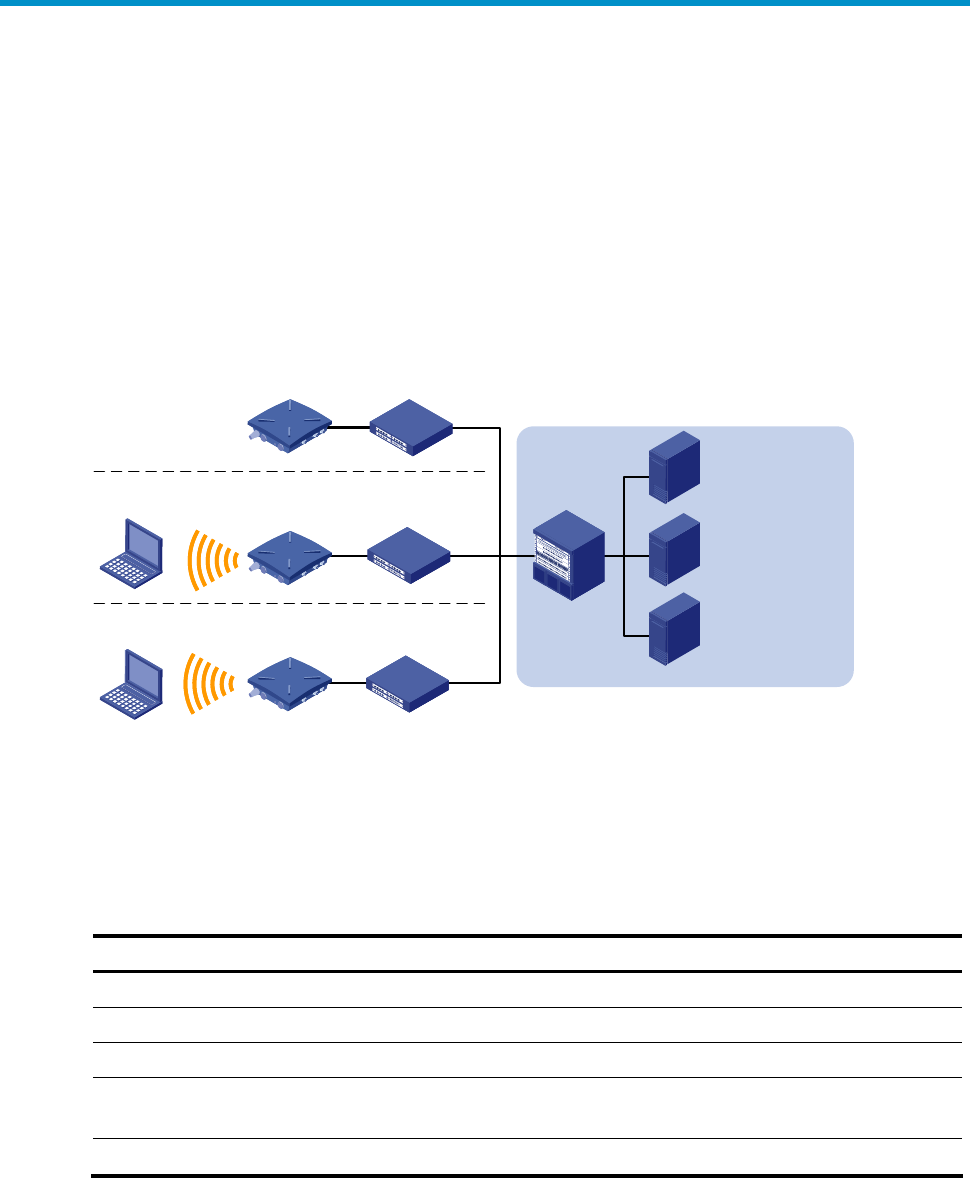
H3C WA2620X-AGNP access point (AP) is a new-generation AP that supports 802.11n and
can work in fit or fat mode. A fit AP can work with an access controller (AC) or wireless
switch to provide WLAN access. A fat AP can provide WLAN access alone. Figure 1 shows a
typical networking scenario for WA2620X-AGNP APs.
Figure 1 Deployment of WA2620X-AGNP APs (in fat mode)
WA2620X-AGNP
Core equipment
room RADIUS server
WLAN
management
system
Service database
server
Switch
Switch
Switch
Switch
Residential community
Seaport or pier
Parking lot
PC
PC
PC
WA2620X-AGNP
WA2620X-AGNP
Hardware specifications
The WA2620X-AGNP AP offers IP66 rated protection and allows for outdoor deployment.
The following sections describe its hardware specifications, LEDs, and ports.
Table 1 Hardware specifications
Item Description
Dimensions (H×W×D) 76 x 245 x 245 mm (2.99 x 9.65 x 9.65 in.)
Weight 2.35 kg (5.18 lb)
Power consumption 12 W (standby) to 24 W (maximum)
Protocols and materials
• IEEE802.11a/b/g/n
• Waterproof cast aluminum + plastic housing
802.at Support for PoE+
2
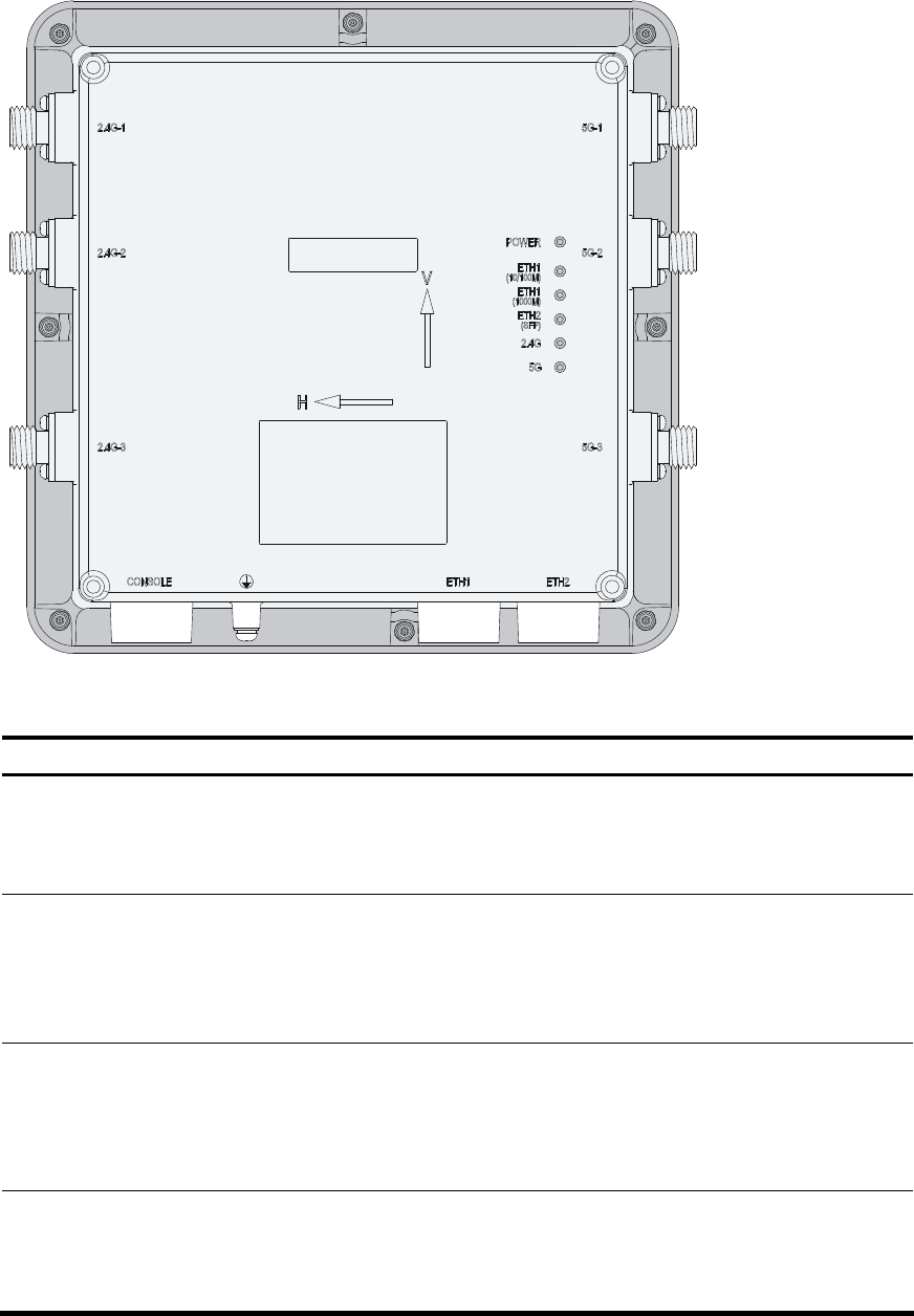
LEDs
Figure 2 WA2620X-AGNP LEDs
Table 2 LED description
LED Color Quantity
Description
POWER
(Power LED) Green 1
Indicates power status:
• On: The AP is powered on.
• Off: The AP is powered off or operates
abnormally.
ETH1 (10/100M)
(10/100M Ethernet
port LED)
Green 1
Indicates Ethernet port status:
• Steady on: A link is present on the port.
• Off: No link is present on the port.
• Blinking: The port is transmitting or receiving
data.
ETH1 (1000M) (GE
port LED) Green 1
Indicates Ethernet port status:
• Steady on: A link is present on the port.
• Off: No link is present on the port.
• Blinking: The port is transmitting or receiving
data.
ETH2 (SFP) (GE fiber
port LED) Green 1
Indicates fiber port status:
• Steady on: A link is present on the port.
• Off: No link is present on the port.
• Blinking: The port is transmitting or receiving

3
LED Color Quantity
Description
data.
2.4G (802.11g/n LED) Green 1
Indicates wireless link status:
• Off: The wireless link is down or fails.
• Slow blinking: The wireless link is normal.
• Fast blinking: Data is being transmitted or
received.
5G (802.11a/n LED) Green 1
Indicates wireless link status:
• Off: The wireless link is down or fails.
• Slow blinking: The wireless link is normal.
• Fast blinking: Data is being transmitted or
received.
Ports
The WA2620X-AGNP AP provides three 2.4 GHz antenna ports and three 5.0 GHz antenna
ports, a console port, Ethernet ports (fiber and copper), a power port, and a grounding
terminal.
4
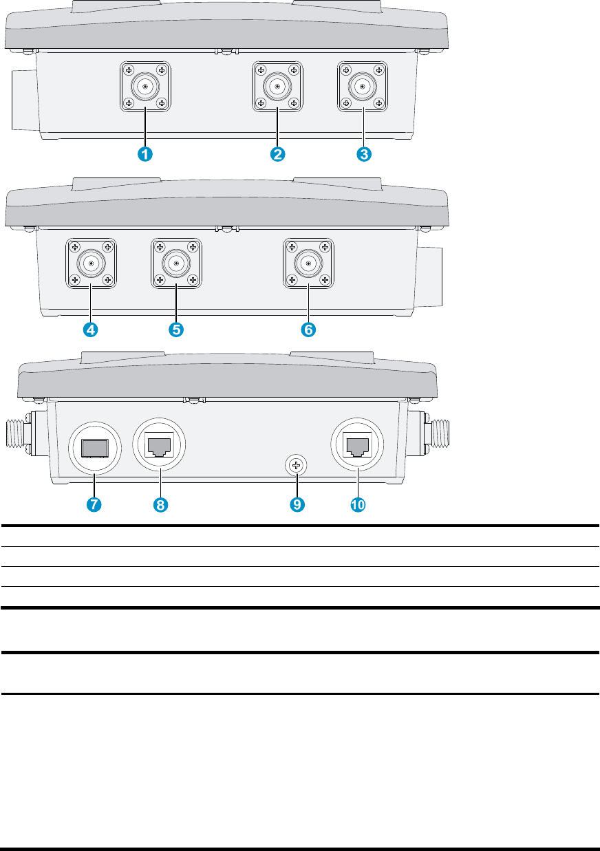
Figure 3 WA2620X-AGNP port layout
1: 2.4G-1 antenna port 2: 2.4G-2 antenna port 3: 2.4G-3 antenna port
4: 5G-1 antenna port 5: 5G-2 antenna port 6: 5G-3 antenna port
7: ETH2 (1000BASE-FX fiber port) 8: ETH 1 (10/100/1000BASE-TX copper port)
9: Grounding terminal 10: Console port
Table 3 Port description
Port Standards
and protocols
Function
ETH 2
1000BASE-FX fiber port
IEEE802.3
SFP MSA
SFF-8472
Connects to the Internet or Metropolitan Area
Network (MAN).
NOTE:
The SFP transceiver module (9/125µm single mode
fiber) uses an LC connector and delivers a
transmission speed of 1250 Mbps (central
wavelength: 1310 nm; output power: –9.5 dBm to
–3 dBm; receive sensitivity ≤ –20 dBm; light
saturation: –3 dBm).

5
Port Standards
and protocols
Function
ETH 1
10/100/1000BASE-TX
copper port
IEEE802.3
IEEE802.3u
IEEE802.3at
Connects to the Internet or MAN and serves as a
PoE port.
2.4G-1/2/3 IEEE802.11b/g/n
Antenna port for 2.4 GHz band
5G-1/2/3 IEEE802.11a/n Antenna port for 5 GHz band
CONSOLE RS/EIA-232 Console port for configuration and management

6
Preparing for installation
This chapter describes how to prepare for the installation of the AP, including the
preparation of tools and installation site survey.
Preparing installation tools
When installing the AP, you may need the tools listed in Table 4. Choose the appropriate
tools according to the installation environment.
Table 4 List of installation tools
Type of tools Tools
General tools Digging tools, adjustable wrench, pliers, Phillips screwdriver
Special tools Cable stripper, crimping pliers, RJ-45 crimping pliers, waterproof sealing tape,
fiber fusion splicer
Auxiliary tools Ladder
Examining the installation site
Before installation, examine the installation site to make sure that the AP will work in a good
environment. You can examine the installation site from the following two aspects.
Installation site selection
Keep the AP away from high temperature, dust, harmful gases, inflammables, explosive
substances, electromagnetic interference sources (heavy-duty radars, radio stations, or
electrical substations), unstable voltage, heavy vibration, or loud noise. The installation site
should be dry, without any leakage, dripping, or dew. The AP should be at least 500 m (0.31
miles) away from the seaside and should not face the direction of sea wind.
In engineering design, the site should be selected according to the network planning and
technical requirements of the communications equipment, and the considerations such as
climate, hydrology, geology, earthquake, electric power, and transportation.
Temperature and humidity
Table 5 Temperature and humidity requirements
Item Range
Operating temperature –40°C to +65°C (–40°F to 149°F)
Storage temperature –40°C to +85°C (–40°F to 185°F)
Operating relative humidity (noncondensing) 0% to 100%
Storage relative humidity (noncondensing) 0% to 100%

7
Power supply
The AP can be powered by a power injector or through PoE+.
1. Power injector
You can use an H3C POE-5 power injector to power the AP. For more information about
how to power the AP through the power injector, see “Connecting the AP to a power
injector.”
NOTE:
The input voltage of the POE-5 power injector must be 85 to 264 VAC (50/60 Hz). The powe
r
injector is not shipped with the AP and must be ordered separately.
2. PoE+
If the switch connected to the AP is PoE+ capable, the AP can be powered by the switch
through the cable between the 10/100/1000BASE-TX port of the AP and the Ethernet port of
the switch.
Grounding and lightning protection
Table 6 Grounding and lightning protection requirements
Item Requirements
Grounding
resistance
• The grounding resistance is usually required to be less than 5 ohms, and less
than 10 ohms in an area with less than 20 thunderstorm days a year. If a
piece of angle steel is buried as the grounding conductor, the grounding
resistance is required to be less than 10 ohms. In an area with a higher
grounding resistance, reduce the grounding resistance by using brine or
resistance reducing agent around the grounding conductor.
• The top of the grounding conductor should be at least 0.7 m (2.30 ft) away
from the ground surface. In cold areas, the grounding conductor should be
buried below the frozen soil layer.
Grounding
connection
• If a grounding strip is available, connect the yellow and green grounding
cable of the AP to the grounding strip. To make a grounding cable, make
sure the cable is with a cross-section area of at least 6 mm2 (0.01 in.2) and a
length of no longer than 3 m (9.84 ft).
• If no grounding strip is available, bury a piece of angle steel/steel tube at
least 0.5 m (1.64 ft) long in the earth to serve as the grounding conductor. In
the case of a piece of angle steel, the size should be at least 50 × 50 × 5 mm
(1.97. × 1.97 × 0.20 in.); in the case of a piece of steel tube, it must be
zinc-plated and have a wall thickness of at least 3.5 mm (0.14 in.). Weld the
yellow and green grounding cable of the AP onto the grounding conductor
and use anti-erosion treatment on the welding joint. The grounding cable
should be as short as possible and must not be coiled.
• Make sure that the grounding terminals of all the lightning arresters of the AP
and the peer device of the AP are well grounded.
Grounding
lead-in
A grounding lead-in is a metal conductor connecting a grounding net and a
grounding strip. The grounding cable of the AP should be connected to the
grounding strip. The grounding lead-in must be 30 m (98.43 ft) or shorter. A
piece of zinc-coated flat steel with a cross-section area of 40 × 4 mm (1.57 ×
0.16 in.) or 50 × 5 mm (1.97 × 0.20 in.) is recommended. Connect the grounding
strip and the grounding lead-in of the AP through the yellow and green
grounding cable with an area of 35 mm2 (0.05 in.2), or weld them directly. Use
anti-erosion treatment on the welding joint.

8
Item Requirements
Power
grounding (AC)
• Use a power cord with a protective earth (PE). Do not use a power cord
with only an L line and an N line.
• The neutral line of the power cord should not be connected with the PGND
of other communications equipment. The L and N lines cannot be
connected.
Lightning rod
In plain areas, the shielding angle of the lightning rod should be less than 45
degrees. In mountainous areas or lightning areas, the shielding angle should be
less than 30 degrees. The lightning protection grounding (for example, the
grounding of the lightning rod) should be connected to the grounding
conductor of the equipment room.
Antenna
• The antenna support is already prepared according to the design
requirements.
• The AP is well grounded according to design requirements.
Network cable Use a shielded twisted pair cable for outdoor installation. Make sure that the
devices at the two ends of the cable are well grounded.
Examining the AP
Before installing the AP, connect the AP to the power source (if a power injector is used)
and the Ethernet and check the status of the LEDs to ensure that the AP is functional. Save
the MAC address of the AP for future use.
9
Installing the AP
The WA2620X-AGNP AP can be mounted on a pole. To ensure the radio coverage, have
the AP installed by professionals. The installation involves the following procedures:
Installing the AP
Installing the outdoor antennas
Connecting cables
Verifying the installation
Powering on the AP
Installing the AP
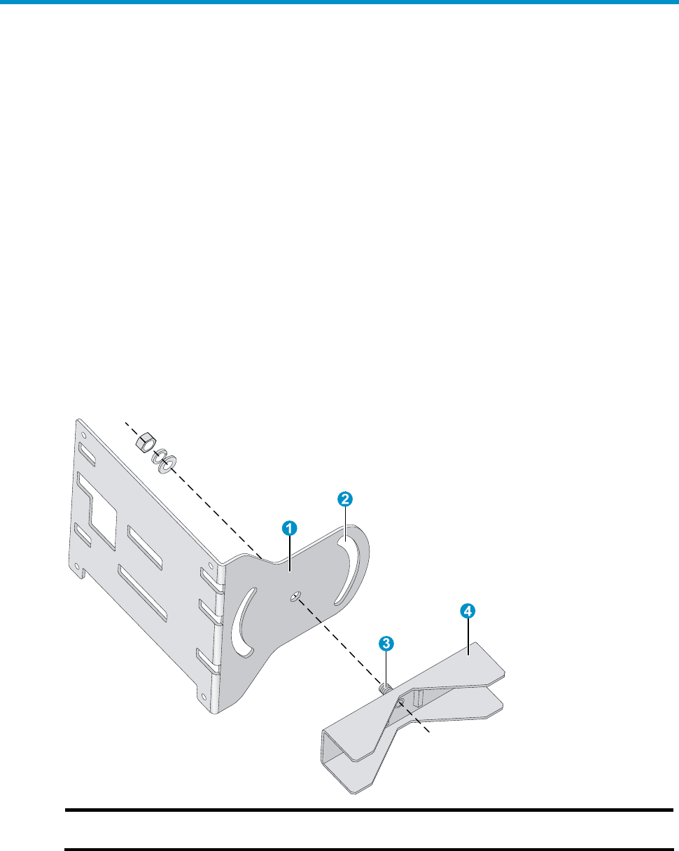
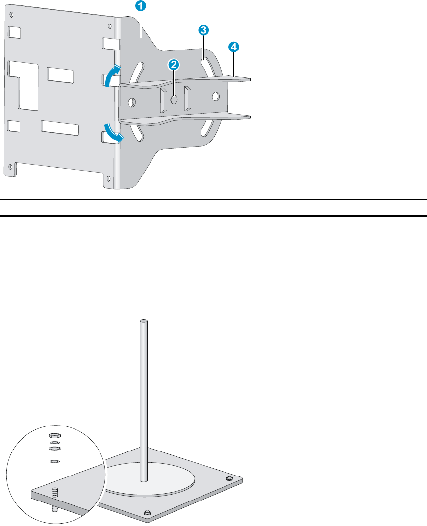
The AP can be fixed to a vertical or horizontal pole whose outer diameter is between 60
mm and 110 mm (2.36 in. and 4.33 in.). The mounting kit includes a pair of V-shaped
brackets, a mounting plate, bolts, and nuts, as shown in Figure 4.
Figure 4 Mounting plate and V-shaped bracket
1: Mounting plate 2: Mounting slot (allows bracket
rotation)
3: Bolt 4: V-shaped bracket
You can adjust the tilt of the AP by rotating the mounting plate around the bolt to help
installation, as shown in Figure 5.
10
Figure 5 Adjust the tilt of the AP
1: Mounting plate 2: Bolt 3: Mounting slot (allows bracket rotation) 4: V-shaped bracket
Pole mounting is suitable for rooftop installation.
Follow these steps to install the AP on a pole:
Step1 Vertically fix the pedestal of the pole to the rooftop or a cement pier on the rooftop with
expansion screws, as shown in Figure 6.
Figure 6 Pole and pedestal
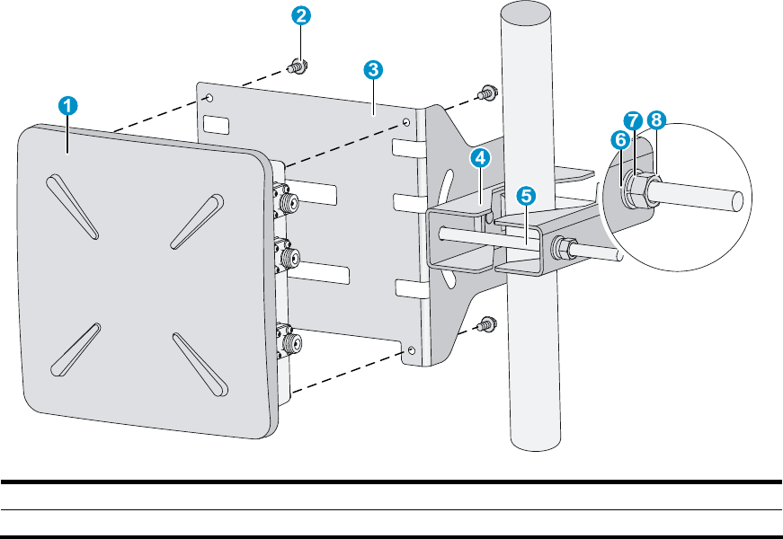
Step2 Fix the V-shaped bracket onto the mounting plate with the bolt.
Step3 Attach another V-shaped bracket to the pole, making sure that the two V-shaped bracket
are level. Insert two long bolts through the screw holes on the two brackets and attach the
bolts, nuts, and flat and spring washers, as shown in Figure 7 and Figure 8.
11
Figure 7 Mount the AP on the pole (vertical)
1: AP 2: Screw (M6 x 12) 3: Mounting plate 4: V-shaped bracket
5: Long bolt 6: #10 flat washer 7: #10 spring washer 8: M10 nut
12
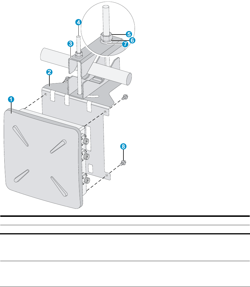
Figure 8 Mount the AP on the pole (horizontal)
1: AP 2: Mounting plate 3: V-shaped bracket 4: Long bolt
5: M10 nut 6: #10 spring washer 7: #10 flat washer 8: Screw (M6 x 12)
Step4 Fix the AP onto the mounting plate with screws and fasten the screws, as shown in Figure 7
and Figure 8.
NOTE:
You can fix the mounting plate on the pole with brackets before or after fixing the AP onto
the mounting plate, whichever is more convenient.
Installing the outdoor antennas
13
Installing a directional antenna on a pole
NOTE:
Ensure that the location of the pole does not hamper the adjustment of antenna direction
and tilt.
Before you install a directional antenna on the pole, make sure that the pole is vertical to
the rooftop surface.
Follow these steps to install a directional antenna:
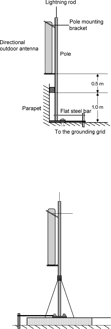
Step1 Weld the lightning rod to the tip of the pole.
Step2 Install the pole on a parapet or cement pier.
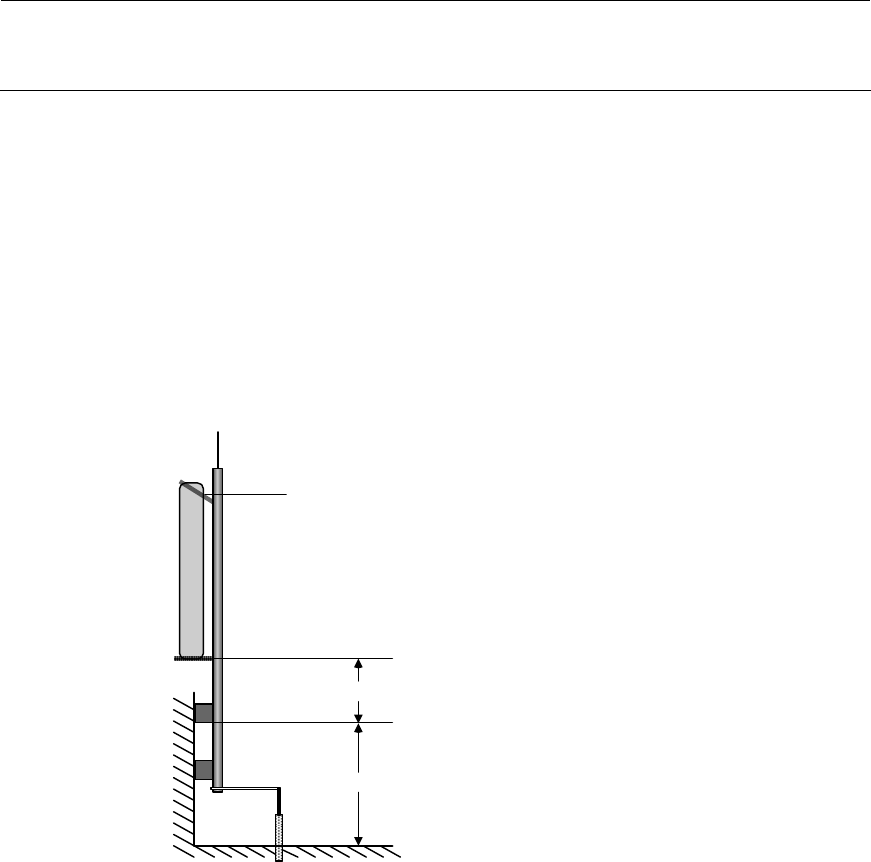
• If there are parapets on the rooftop and the height of the parapets is no less than 1.2
m (3.94 ft), you can fix the pole on a parapet with expansion screws and fix the
directional antenna on the pole with the pole mounting bracket, as shown in Figure 9.
Figure 9 Install a directional antenna on a parapet (I)
Lightning rod
Directional outdoor
antenna Pole
Parapet
Pole mounting bracket
0.5 m
1.2 m
Flat steel bar
To the grounding grid
• If there are parapets on the rooftop and the height of the parapets is less than 1.2 m
(3.94 ft), you can fix the pole on a parapet at one point with expansion screws and fix
the bottom end of the pole to the rooftop surface, and then fix the directional
antenna on the pole with the pole mounting bracket, as shown in Figure 10.
14
Figure 10 Install a directional antenna on a parapet (II)
• If there is no parapet on the rooftop, fix the pole to the rooftop surface or a cement
pier on the rooftop with expansion screws and stabilize the pole with steel wires. Then,
install the directional antenna on the pole, as shown in Figure 11.
Figure 11 Install a directional antenna on a cement pier
Cement pier
Steel wire
Pole
Directional
outdoor antenna
Lightning rod
Pole mounting
bracket
Flat steel bar
To the grounding grid
Steel wire
Step3 Connect the pole to a grounding grid with a flat steel bar (40 x 4 mm or 1.57 x 0.16 in.).
Step4 Fix the antenna on the pole with the pole mounting bracket.
Connecting cables

15
WARNING!
Before connecting any cable, make sure that all power lines are disconnected and
locked out and that no hazardous voltage is present on the neutral (N) line.
CAUTION:
Make sure that the outer sheath of cables is intact and does not absorb moisture to
protect the AP from water leak.
External cables may include antenna cable, Ethernet cable, fiber cable, grounding cable,
and power cord.
Connecting the antenna cables
The antenna cables connect the antenna ports (2.4 GHz and 5 GHz) to the outdoor
antennas.
Follow these steps to connect the antenna cables:
Step1 Connect the antenna cables to the antenna ports of the AP at one end and to the
outdoor antennas at the other end.
• For 2 x 2 MIMO antennas, connect the cables to the 2.4 G-1/3 and 5G-1/3 antenna
ports on the AP.
• For 3 x 3 MIMO antennas, connect the cables to the 2.4 G-1/2/3 and 5G-1/2/3
antenna ports on the AP, respectively.
Step2 Wrap the connections with insulating tape and apply several layers of waterproof sealing
tape over the insulating tape.
NOTE:
• No antenna arrestor is needed. The WA2620X-AGNP AP provides lightning arresting
function.
• Make sure that the grounding cables are well grounded during outdoor deployment.
• You have the option to order the standard ready-made antenna cables, or order
cables of desired lengths and N-type antenna connectors and make antenna cables
on-site as needed.
• Stretch the waterproof sealing tape till the width of the tape is reduced to 3/4 of the
original width and wrap the waterproof sealing tape around the cable to achieve
desired waterproof performance.
Connecting the Ethernet cable
CAUTION:
Observe the following procedure when connecting the copper cable. Otherwise, the AP
might be damaged.
Step1 Route the Ethernet cable with waterproof sheath from the equipment room to the AP.
16
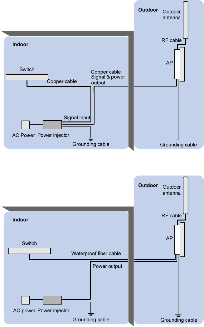
Figure 12 Connect a copper cable
Figure 13 Connect a fiber cable
17
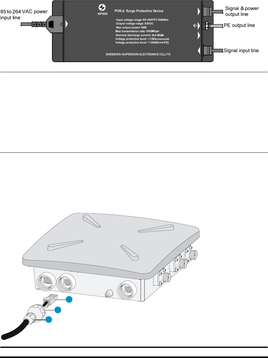
Figure 14 Power injector
Green normal
Dark failure
Power in
Data in
Power&data out
NOTE:
• If the AP is powered by a PoE+ switch, no power injector is needed. Make sure
that the
PoE+ switch can support the maximum power consumption of the AP.
• If a fiber cable is used to transmit data, the copper cable only provides power and
does not transmit data.
• The Ethernet port marked with “Signal & power output” on the power injector must be
connected to the AP.
• Make sure that the installation of the AP is complete before powering on the AP,
regardless of whether the AP is powered through PoE+ or by a power injector.
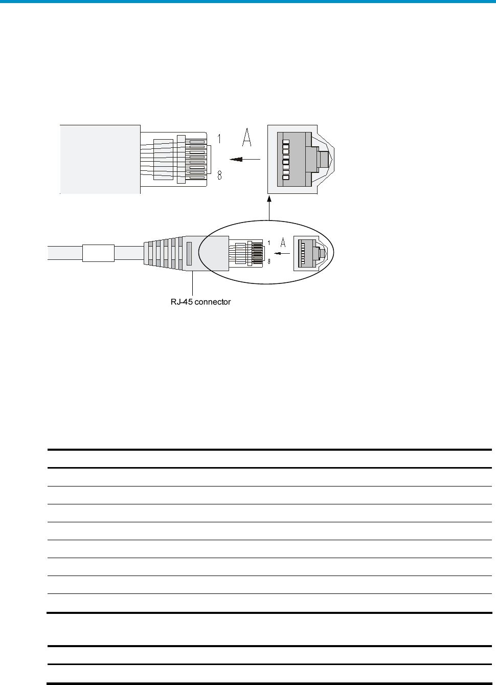
Step2 Insert the copper cable through the liquid tight adapter and crimp an RJ-45 connector on
the end of the cable. For more information about how to crimp an RJ-45 connector on a
cable ,see “Appendix A Crimping an RJ-45 connector”.
Step3 Connect the cable to the copper port of the AP.
Figure 15 Connect the copper cable to the copper port of the AP
1
2
3
1: RJ-45 connector 2: Liquid tight adapter 3: Sealing nut
Step4 Make sure the sealing nut is loose. Tighten the liquid tight adapter, and then tighten the
sealing nut.
Step5 Seal the connection with waterproof sealing tape.
18
Connecting the fiber cable
CAUTION:
• Observe the following procedure when connecting the fiber cable. Otherwise, the AP
might be damaged.
• When a fiber cable is used to transmit data, both ends of the cable must use
appropriate SFP transceiver modules. The SFP transceiver modules provided by H3C
meet the outdoor deployment requirements, use single mode fiber, and have a
transmission distance of 15 km (9.32 mi).
If the AP is connected to the switch through a fiber cable, an SFP transceiver module and a
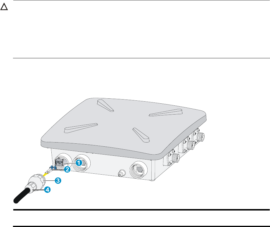
liquid tight adapter are required at the AP side, as shown in Figure 16.
Figure 16 Connect the fiber cable to the fiber port of the AP
1: SFP transceiver
module
2: Fiber connector 3: Liquid tight adapter 4: Sealing nut
Follow these steps to connect a fiber cable:
Step1 Insert an SFP transceiver module into the fiber port of the AP.
Step2 Insert an LC fiber connector with liquid tight adapter to the SFP transceiver module.
Step3 Make sure the sealing nut is loose. Tighten the liquid tight adapter, and then tighten the
sealing nut.
Step4 Seal the connection with waterproof sealing tape.

19
NOTE:
• The optional fiber cable is a 10-meter pigtail with waterproof sheath. One end of the
pigtail uses an LC connector and a liquid tight adapter and is inserted into the fiber port
of the AP and the other end uses an SC connector and is connected to an end user
terminal or switch.
• If the fiber is connected to a fiber termination box, connect the SC connector to a pair
of SC sockets. The one marked as A is the receiving port (RX) of the AP and must be
connected to the transmitting port (TX) of the peer device; the one marked as B is the
TX port of the AP and must be connected to the RX port of the peer device. Usually,
fiber termination boxes are not waterproof. Put the fiber termination box indoor or in a
waterproof cabinet.
• If the fiber is connected to a fiber connector box, cut off the SC connector and splice
the fiber end with the connector on the connector box. The pigtail marked as A is
connected to the RX port of the AP and the TX port of the peer device; the pigtail
marked as B is connected to the TX port of the AP and the RX port of the peer device.
Fiber connector boxes are usually waterproof and can be buried underground or
mounted on a pole.
Connecting the AP to the power source
The WA2620X-AGNP AP can be powered by a power injector or a PoE+ switch.
Connecting the AP to a power injector
As shown in Figure 14, follow these steps to connect the power injector to the AP:
Step1 Connect the power input line to an AC power source.
Step2 Connect the signal & power output line to the copper port of the AP.
Step3 Connect the signal input line to a switch or an access controller.
Step4 Ground the PE output line of the power injector.
Connecting the AP to a PoE+ capable switch
To power the AP by using a PoE+ capable switch, connect the 10/100/1000BASE-TX port of
the AP to an Ethernet port of the switch through an Ethernet cable.
NOTE:
• If the AP is powered by a PoE+ switch, the power injector is not needed. Make sure
that
the PoE+ port can support the maximum power consumption of the AP.
• If the AP is powered by a power injector, put the power injector at the switch side, and
the switch connected to the power injector does not need to be PoE+ capable.
• Make sure that the installation of the AP is complete before powering on the AP,
regardless of whether the AP is powered through PoE+ or by a power injector.
Connecting the grounding cable
Connect the grounding terminal of the AP to the grounding point with the yellow and
green grounding cable shipped with the AP, as shown in Figure 3. For more information
about the procedure, see “Grounding and lightning protection”.

20
NOTE:
If the AP is powered by a power injector, the PE output line of the power injector must also
be grounded.
Verifying the installation
After the installation and cabling, check the following items before powering on the AP:
• The power source meets the power specification of the AP;
• The AP is well grounded;
• The power input cable and the Ethernet cables are correctly connected;
• The outdoor antennas are installed;
• If the AP is powered by a PoE+ switch, an Ethernet lightning arrestor (which is not
shipped with the AP) is installed on the AP.
Powering on the AP
Make sure that all the cables are correctly connected. Then, switch on the external power
source and check the power LED of the AP against Table 2.
CAUTION:
If the AP is installed outdoor, the Ethernet cable must be waterproof and the connection
at the AP port must be sealed with waterproof sealing tape.
21
Logging in to the AP
NOTE:
A fit AP is zero-configuration and is managed by an access controller or wireless switch. This
chapter describes how to log in to a fat AP on a web interface.
Use the following factory default settings to log in to a fat AP on a web interface:
• Username: admin
• Password: h3capadmin
• IP address: 192.168.0.50 (mask: 255.255.255.0)
Follow these steps to log in to the AP:
Step1 Connect the AP to a computer with an Ethernet cable.
Step2 Set the IP address of the computer to an address (such as 192.168.0.100 with a mask of
255.255.255.0) that is in the same subnet as the AP.
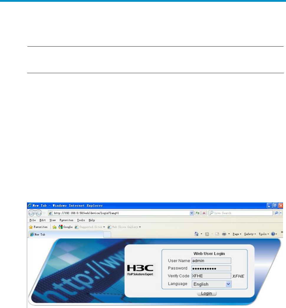
Step3 Launch the web browser and input the address (http://192.168.0.50) of the AP in the
address bar and press Enter. The login interface appears, as shown in Figure 17. On the
web interface, enter the default username and password and the verification code, and
click Login.
Figure 17 Web interface
22
Appendix A Crimping an RJ-45 connector
You must insert the Ethernet cable through the liquid tight adapter before crimping an
RJ-45 connector on the end of the cable (usually category 5 or category 5E cable).
Figure 18 RJ-45 connector
The following describes two common types of cables and how to make them.
• Straight-through cable: The colored wires are of the same sequence at the two ends
of the cable. A straight-through cable is usually used to connect these devices: PC to
hub or switch, router to hub or switch.
• Crossover cable: The colored wires are of different sequences at the two ends of the
cable. A crossover cable is usually used to connect these devices: PC to PC, router to
router, or PC to router.
Table 7 Straight-through cable pin-outs
RJ45 pin Signal Wire Signal direction RJ45 pin
1 TX+ White-orange
Æ 1
2 TX- Orange
Æ 2
3 RX+ White-green
Å 3
4 - Blue - 4
5 - White-blue - 5
6 RX- Green
Å 6
7 - White-brown - 7
8 - Brown - 8
Table 8 Crossover cable pin-outs
RJ45 pin Signal Wire Signal direction RJ45 pin
1 TX+ White-orange
Æ 3

23
RJ45 pin Signal Wire Signal direction RJ45 pin
2 TX- Orange
Æ 6
3 RX+ White-green
Å 1
4 - Blue - 4
5 - White-blue - 5
6 RX- Green
Å 2
7 - White-brown - 7
8 - Brown - 8
NOTE:
• The Ethernet ports of the AP are autosensing and can recognize both types of cables.
• When making a cable, follow the exact sequence listed in Table 7 or Table 8.
• When the AP is installed outdoors, the cable must be waterproof. If possible, use
waterproof tubing to protect the cable.

Compliance and Safety Manual

i
Contents
Safety Information Sicherheits informationen 安全信息 1
Conventions Used Symbole Erläuterung 应用惯例 1
Important Safety Information/Wichtige Sicherheitshinweise/重要安
全信息 2
Electricity Safety Elektrische Sicherheit 用电安全 3
Regulatory Compliance Information 5
Regulatory compliance standards (标题 2) 5
Support Antennas & Accessories information 6
EU Compliance information 6
CE Marking 6
EU Country Restriction in 2.4GHz band 9
EU Country Restriction in 5GHz band 10
WEEE Directive–2002/96/EC 11
USA regulatory compliance 11
FCC Part 15 11
Canada regulatory compliance 13
ICES-003 13
RF Compliance 13
Brazil RF Compliance 14
Korea RF Compliance 14
Taiwan regulatory statement 15

ii
List of Tables
Table 1 Safety symbol and description............................................................ 1
Table 2 Regulatory compliance standards...................................................... 5
Table 3 Authorized Antennas & Accessories................................................. 6
Table 4 Equipment may be operated in the following country: ............ 6
Table 5 R&TTE declaration statements:........................................................... 7
Table 6 Europe-Restrictions for Use of 5GHz Frequencies in European
Community Countries.................................................................................10

1
Safety Information Sicherheits
informationen 安全信息
Conventions Used Symbole Erläuterung 应用
惯例
The symbols in this manual are shown in the following table. They are
used to remind the reader of the safety precautions during
equipment installation and maintenance.
Die Symbole in diesem Handbuch verwendeten sind in der folgenden
Tabelle dargestellt. Diese Symbole sollen das Personal während der
Installation und Instandhaltung der Ausrüstung an die Wichtigkeit
der im Handbuch aufgeführten Sicherheitsvorschriften erinnern.
以下表格中的安全标识,是用来提示读者在进行设备安装和维护时的安
全预防要求。
Table 1 Safety symbol and description
Sicherheitssymbole und Beschreibung 安全标识和描述
Safety
Symbol
Symbole
安全标识
Description
Erläuterung
描述
Generic alarm symbol: To suggest a general safety concern
Alarm: Hinweis auf ein generelles Sicherheitsproblem
一般注意标识:用于一般安全提示
ESD protection symbol: To suggest electrostatic-sensitive
equipment.
ESD-Schutz: Hinweis auf Beschädigung infolge
elektrostatischer Entladung
防静电标识:用于表示静电敏感的设备
Electric shock symbol: To suggest a danger of high voltage
2
Safety
Symbol
Symbole
安全标识
Description
Erläuterung
描述
Elektrischer Schlag: Hinweis auf Gefährdung durch
Hochspannung
电击防护标识:用于表示高压危险
Important Safety Information/Wichtige
Sicherheitshinweise/重要安全信息
Caution: You must read all of the installation instructions in the
Installation Guide supplied with your equipment and the following
safety instructions before installation or operation.
Achtung: Sie müssen vor der Installation oder Bedienung das mit Ihrer
Anlage mitgelieferten Installationshandbuch und die folgende
Sicherheitshinweise lesen.
注意:在安装和操作本设备时,务必阅读设备安装手册的内容,以及下文
的所有安全说明。
Caution: Do not block ventilation openings while the system is on, and
keep at least 5 cm distance from ventilation openings and walls or other
things which may block the openings.
Achtung: Blockieren Sie die Lüftungsmündungen nicht, wenn das
System läuft. Stellen Sie die Lüftungsmündungen mindestens 5 cm
entfernt von der Wände oder anderen Sachen, die die Mündungen
blockieren können.
注意:设备在工作时必须确保通风口的畅通,确保设备离墙壁或是其它的
可能堵塞通风口的物体的间距至少 5cm。
WARNING: Before the power cable is installed or removed, the power
switch must be turned off.
Warnung: Das System muss stets abgeschaltet werden, bevor die
Zuleitung angebracht oder entfernt wird.
警告:在安装、移动线缆之前,请切断电源。
WARNING: Before the power cable is connected, it must be confirmed
that the power cable and label comply with the requirements of the
3
actual installation.
Warnung: Überprüfen Sie vor dem Anbringen der Zuleitung immer, ob
das von Ihnen verwendete Kabel den Anforderungen entspricht.
警告:在进行线缆连接前,请确认线缆和线缆的标识与实际安装要求是一
致的。
WARNING: The unit must be permanently connected to the protective
ground before operation. The cross-sectional area of the protective
earthing / grounding conductor shall be at least 0.75 mm2.
Warnung: Diese Anlage muss vor der Inbetriebnahme ständig an die
Schutzleiter angeschlossen werden. Die Querschnittsfläche des
Schutzerdungsleiters soll mindestens 0.75 mm2 betragen.
警告:进行设备/系统操作前,请确保永久接地,并且用于进行保护接地连
接的接地线截面不小于0.75 mm2。
WARNING: To ensure the equipment mounted on the wall firmly, please
use nail at least 4.2 mm diameter and the nail cap at least 8 mm
diameter.
Warnung: Um die Sicherheit der Ausrüstung auf der Wand, der Nagel in
der Wand muss einen Durchmesser 4.2 mm mindestens haben und der
Durchmesser von der Nagelkappe muss groesser als 8 mm sein.
警告:为确保设备紧固的安装在墙上,请用直径最小是4.2mm钉子,并且
钉子帽的直径要大于8mm。
Electricity Safety Elektrische Sicherheit 用电安
全
• Conducting articles, such as watch, hand chain, bracelet and ring are
prohibited during the operation.
• Es ist nicht erlaubt während dieser Arbeiten leitende Gegenstände
wie Uhren, Armbänder, Armreifen und Ringe am Körper zu tragen.
• 在操作中不能穿戴导电性的物品,如:手表,手琏,手镯和项链等。
• When water is found in the rack, or the rack is damp, please
immediately switch off the power supply.
4
• Sollte sich Wasser im Baugruppenträger befinden oder der
Baugruppenträger feucht sein, ist die Energiezufuhr sofort zu
unterbrechen und das System abzuschalten.
• 当有液体进入机架或机架有损坏时,请立即切断电源。
• When operation is performed in a damp environment, make sure that
water is kept off the equipment.
• Muss in einem feuchten Umgebung gearbeitet werden, ist
sicherzustellen, dass kein Wasser in die Ausrüstung dringen kann.
• 在潮湿环境下进行安装时,请避免液体进入设备。

5
Regulatory Compliance
Information
Regulatory compliance standards
Table 2 Regulatory compliance standards
Discipline Standards
EMC
FCC Part 15 (CFR 47) Subpart B section 15.107&15.109
Class B
ICES-003 Class B
EN 61000-3-2
EN 61000-3-3
EN55024
EN55022
EN 301 489-1
EN 301 489-17
Safety
UL 60950-1
CAN/CSA C22.2 No 60950-1
IEC 60950-1
EN 60950-1
AS/NZS 60950-1
RF
FCC Part 15 subpart C section 15.207 & 15.209 &
15.247& 15.205; subpart D section 15.407
FCC Bulletin OET-65C
RSS-210
EN 300 328
EN 301 893
6
Support Antennas & Accessories
information
This product can be used with the following antennas and
accessories:
Table 3 Authorized Antennas & Accessories
Item Description Exclusions
Supplied Antenna None
JG291A HP 2.4GHz 12dBi MIMO 3-element
Outdoor/Indoor Panel Antenna None
JG292A HP 5GHz 11dBi MIMO 3-element
Outdoor/Indoor Panel Antenna None
This product does not contain any user serviceable components. Any
unauthorized product changes or modifications will invalidate the
warranty and all applicable regulatory certifications and approvals.
This product must be installed by a professional technician/ installer.
EU Compliance information
CE Marking
Table 4 Equipment may be operated in the following country:
AT BE CY CZ DK EE FI FR
DE GR HU IE IT LV LT LU
MT NL PL PT SK SI ES SE
GB IS LI NO CH BG RO TR

7
1. Select the country in which the product is installed to ensure product
operation is in compliance with local regulations. For more
information about how to select the country, see command about
country-code in "WLAN Command Reference".
2. Intended use: IEEE 802.11 a/b/g/n radio LAN device.
3. This product must maintain a minimum body to antenna distance of
20cm.Under these conditions this product will meet the Basic
Restriction limits of 1999/519/EC(Council Recommendation of 12 July
1999 on the limitation of exposure of the general public to
electromagnetic fields(0Hz-300GHz)).
Table 5 R&TTE declaration statements:
Česky
[Czech]
HP Coporation tímto prohlašuje, že tento RLAN je ve shodě se
základními požadavky a dalšími příslušnými ustanoveními
směrnice 1999/5/ES.
Dansk
[Danish]
Undertegnede HP Corporation erklærer herved, at følgende
udstyr RLAN overholder de væsentlige krav og øvrige relevante
krav i direktiv 1999/5/EF.
Deutsch
[German]
Hiermit erklärt HP Corporation, dass sich das Gerät RLAN in
Übereinstimmung mit den grundlegenden Anforderungen und
den übrigen einschlägigen Bestimmungen der Richtlinie
1999/5/EG befindet.
Eesti
[Estonian]
Käesolevaga kinnitab HP Corporation seadme RLAN vastavust
direktiivi 1999/5/EÜ põhinõuetele ja nimetatud direktiivist
tulenevatele teistele asjakohastele sätetele.
English
Hereby, HP Corporation, declares that this RLAN is in
compliance with the essential requirements and other relevant
provisions of Directive 1999/5/EC.
Español
[Spanish]
Por medio de la presente HP Corporation declara que el RLAN
cumple con los requisitos esenciales y cualesquiera otras
disposiciones aplicables o exigibles de la Directiva 1999/5/CE.
Ελληνική
[Greek]
ΜΕ ΤΗΝ ΠΑΡΟΥΣΑ HP Corporation ∆ΗΛΩΝΕΙ ΟΤΙ RLAN
ΣΥΜΜΟΡΦΩΝΕΤΑΙ ΠΡΟΣ ΤΙΣ ΟΥΣΙΩ∆ΕΙΣ ΑΠΑΙΤΗΣΕΙΣ ΚΑΙ ΤΙΣ
ΛΟΙΠΕΣ ΣΧΕΤΙΚΕΣ ∆ΙΑΤΑΞΕΙΣ ΤΗΣ Ο∆ΗΓΙΑΣ 1999/5/ΕΚ.
Français
[French]
Par la présente HP Corporation déclare que l'appareil RLAN est
conforme aux exigences essentielles et aux autres dispositions

8
pertinentes de la directive 1999/5/CE.
Italiano
[Italian]
Con la presente HP Corporation dichiara che questo RLAN è
conforme ai requisiti essenziali ed alle altre disposizioni
pertinenti stabilite dalla direttiva 1999/5/CE.
Latviski
[Latvian]
Ar šo HP Corporation deklarē, ka RLAN atbilst Direktīvas
1999/5/EK būtiskajām prasībām un citiem ar to saistītajiem
noteikumiem.
Lietuvių
[Lithuanian]
Šiuo HP Corporation deklaruoja, kad šis RLAN atitinka esminius
reikalavimus ir kitas 1999/5/EB Direktyvos nuostatas.
Nederlands
[Dutch]
Hierbij verklaart HP Corporation dat het toestel RLAN in
overeenstemming is met de essentiële eisen en de andere
relevante bepalingen van richtlijn 1999/5/EG.
Malti
[Maltese]
Hawnhekk, HP Corporation, jiddikjara li dan RLAN jikkonforma
mal-ħtiġijiet essenzjali u ma provvedimenti oħrajn relevanti li
hemm fid-Dirrettiva 1999/5/EC.
Magyar
[Hungarian]
Alulírott, HP Corporation nyilatkozom, hogy a RLAN megfelel a
vonatkozó alapvetõ követelményeknek és az 1999/5/EC
irányelv egyéb elõírásainak.
Polski
[Polish]
Niniejszym HP Corporation oświadcza, że RLAN jest zgodny z
zasadniczymi wymogami oraz pozostałymi stosownymi
postanowieniami Dyrektywy 1999/5/EC.
Português
[Portuguese]
HP Corporation declara que este RLAN está conforme com os
requisitos essenciais e outras disposições da Directiva
1999/5/CE.
Slovensko
[Slovenian]
HP Corporation izjavlja, da je ta RLAN v skladu z bistvenimi
zahtevami in ostalimi relevantnimi določili direktive 1999/5/ES.
Slovensky
[Slovak]
HP Corporation týmto vyhlasuje, že RLAN spĺňa základné
požiadavky a všetky príslušné ustanovenia Smernice 1999/5/ES.
Suomi
[Finnish]
HP Corporation vakuuttaa täten että RLAN tyyppinen laite on
direktiivin 1999/5/EY oleellisten vaatimusten ja sitä koskevien
direktiivin muiden ehtojen mukainen.
Svenska
[Swedish]
Härmed intygar HP Corporation att denna RLAN står I
överensstämmelse med de väsentliga egenskapskrav och
övriga relevanta bestämmelser som framgår av direktiv
1999/5/EG.
9
Íslenska
[Icelandic]
Hér með lýsir HP Corporation yfir því að RLAN er í samræmi við
grunnkröfur og aðrar kröfur, sem gerðar eru í tilskipun
1999/5/EC.
Norsk
[Norwegian]
HP Corporation erklærer herved at utstyret RLAN er i samsvar
med de grunnleggende krav og øvrige relevante krav i direktiv
1999/5/EF.
A copy of the signed Declaration of Conformity can be downloaded
from:
• http://www.hp.eu/certificates
Table 6 Overview of Regulatory Requirements for Wireless LANs
Frequency Band
(MHz) Max Power
Level (EIRP) (mW)
Indoor ONLY Indoor and
Outdoor
2400 – 2483.5 100 mW X
5150 – 5350 200 mW X
5470 – 5725 1000 mW X
NOTE:
Dynamic Frequency Selection and Transmit Power Control is
required in the 5250- to 5350-MHz and 5470- to 5725-MHz
frequency range.
EU Country Restriction in 2.4GHz band
The products may be used indoors or outdoors in all countries of the
European Community using the 2.4GHz band: Channel 1-13, except
where noted below.
In France, the output power is restricted to 10 mW EIRP when the
product is used outdoors in the band 2454 - 2483.5 MHz. There are
no restrictions when used in other parts of the 2.4 GHz band.

10
EU Country Restriction in 5GHz band
1. In Italy the end-user must apply for a license from the national
spectrum authority to operate this device outdoors.
2. To remain in conformance with European spectrum usage laws for
Wireless LAN operation, the above 2.4GHz and 5GHz channel
limitations apply. The user should check the current channel of
operation. If operation is occurring outside of the allowable
frequencies as listed above, the user must cease operating the
product at that location and consult the local technical support staff
responsible for the wireless network.
3. This device must be used with the radar detection feature required
for European Community operation in the 5GHz bands. This device
will avoid operating on a channel occupied by any radar system in
the area. The presence of nearby radar operation may result in
temporary interruption in communications of this device. The Access
Point’s radar detection feature will automatically restart operation on
a channel free of radar. You may consult with the local technical
support staff responsible for the wireless network to ensure the
Access Point device(s) are properly configured for European
Community operation.
Table 7 Europe-Restrictions for Use of 5GHz Frequencies in European
Community Countries
Allowed
Frequency Bands Allowed Channel
Numbers Countries
5.15-5.35&
5.470-5.725GHz
36,38,40,44,46,48,52,54,
56,60,62,64,100,102,104
,108,110,112,116,118,12
0,124,126,128,132,134,1
36,140
Austria, Belgium, Bulgaria,
Cyprus, Czech Republic,
Denmark, Estonia, Finland,
France, Germany, Greece,
Hungary, Iceland, Ireland,
Italy, Latvia, Liechtenstein,
Lithuania, Luxembourg,
Malta, Netherlands,
Norway, Poland, Portugal,
Slovakia, Slovenia, Spain,
Sweden, Switzerland, U.K.
11
WEEE Directive–2002/96/EC
The products this manual refers to are covered by the Waste Electrical
& Electronic Equipment (WEEE) Directive and must be disposed of in
a responsible manner.
USA regulatory compliance
FCC Part 15
US Federal Communications Commission (FCC) EMC
Compliance
The product complies with Part 15 of the FCC Rules. Operation is
subject to the following two conditions:
1. This device may not cause harmful interference.
2. This device must accept any interference received, including
interference that may cause undesired operation.
This device has been tested and found to comply with the limits for a
Class B digital device pursuant to Part 15 of the FCC Rules. These
limits are designed to provide reasonable protection against harmful
interference in a residential installation. This device generates, uses,
and can radiate radio frequency energy, and if not installed and used
in accordance with the instructions, may cause harmful interference
to radio communications. However, there is no guarantee that
interference will not occur in a particular installation. If this device
does cause harmful interference to
radio/television reception, which can be determined by turning the
device off and on, the user is encouraged to try to correct the
interference by one or more of the following measures:

12
• Reorient or relocate the receiving antenna.
• Increase the separation between the equipment and the receiver.
• Connect the equipment into an outlet on a circuit different from that
to which the receiver is connected.
• Consult the dealer or an experienced radio/TV technician for help.
Note:
Any changes or modifications not expressly approved by the party
responsible for compliance could void the user’s authority to operate
this equipment.
RF Requirements
1. RF exposure Hazard Warning
This device generates and radiates radio-frequency energy. In order
to comply with FCC radio-frequency exposure guidelines for an
uncontrolled environment, this equipment must be installed and
operated while maintaining a minimum body to antenna distance of
20 cm (approximately 8 in.)
2. RF Frequency Requirements
This equipment complies with FCC RF radiation exposure limits set
forth for an uncontrolled environment. This device and its antenna
must not be co-located or operating in conjunction with any other
unauthorized antenna or transmitter.
For outdoor use: the equipment is with frequency band in 2400 -
2483.5 MHz, 5250-5350 MHz, and 5725-5850 MHz.
13
Antennas
Only use the supplied antenna. Unauthorized antennas,
modifications or change to the antennas could violate FCC
regulations and void the user’s authority to operate the equipment.
Canada regulatory compliance
ICES-003
This Class B digital apparatus complies with Canadian ICES-003.
Cet appareil numérique de la classe B est conforme à la norme
NMB-003 du Canada.
RF Compliance
This device complies with Industry Canada licence-exempt RSS
standard(s).
Le présent appareil est conforme aux CNR d'Industrie Canada
applicables aux appareils radio exempts de licence.
Operation is subject to the following two conditions: (1) this device
may not cause interference, and (2) this device must accept any
interference, including interference that may cause undesired
operation of this device.
L ‘ utilisation de ce dispositif est autorisée seulement aux conditions
suivantes: (1) il ne doit pas produire de brouillage et (2) l’ utilisateur
du dispositif doit étre prêt à accepter tout brouillage radioélectrique
reçu, même si ce brouillage est susceptible de compromettre le
fonctionnement du dispositif.
The term "IC" before the equipment certification number only
signifies that the Industry Canada technical specifications were met.
To reduce potential radio interference to other users, the antenna
type and its gain should be so chosen that the equivalent
isotropically radiated power (EIRP) is not more than that required for
successful communication. To prevent radio interference to the

14
licensed service, this device is intended to be operated indoors and
away from windows to provide maximum shielding. Equipment (or its
transmit antenna) that is installed outdoors is subject to licensing.
Pour empecher que cet appareil cause du brouillage au service
faisant l'objet d'une licence, il doit etre utilize a l'interieur et devrait
etre place loin des fenetres afin de Fournier un ecram de blindage
maximal. Si le matriel (ou son antenne d'emission) est installe a
l'exterieur, il doit faire l'objet d'une licence.
This device must not be co-located or operated in conjunction with
any other unauthorized antenna or transmitter.
For outdoor use: the equipment is with frequency band in 2400 -
2483.5 MHz, 5250-5350 MHz, and 5725-5850 MHz.
Brazil RF Compliance
Este produto está homologado pela ANATEL, de acordo com os
procedimentos regulamentados pela Resolução 242/2000 e atende
aos requisitos técnicos aplicados.
Este equipamento opera em caráter secundário, isto é, não tem
direito a proteção contra interferência prejudicial, mesmo de
estações do mesmo tipo, e não pode causar interferência a sistemas
operando em caráter primário.
Para maiores informações, consulte o site da ANATEL –
www.anatel.gov.br
Korea RF Compliance
This device may cause radio interference during its operation.
Therefore service in relation to human life security is not available.

15
Taiwan regulatory statement
1. 經型式認證合格之低功率射頻電機,非經許可,公司、商號或使用者均不得擅
自變更頻率、加大功率或變更原設計之特性及功能。
2. 射頻電信終端設備之使用不得影響飛航安全及干擾合法通信;經發現有干擾現
象時,應立即停用,並改善至無干擾時方得繼續使用。所謂合法通信,係指依
電信法規定作業之無線電信。低功率射頻電機須忍受合法通信或工業、科學及
醫療用電波輻射性電機設備之干擾。
3. 輸入、製造射頻電信終端設備之公司、商號或其使用者違反本辦法規定,擅自
使用或變更無線電頻率、電功率者,除依電信法規定處罰外,電信總局並得撤
銷其審驗合格證明。
4. 本機限在不干擾合法電台與不受被干擾保障條件下於室內使用。
5. 在5.25-5.35 秭赫頻帶內操作之無線資訊傳輸設備,限於室內使用。
6. 無線資訊傳輸設備的製造廠商應確保頻率穩定性,如依製造廠商使用手冊上所
述正常操作,發射的信號應維持於操作頻帶中。
7. 為減少電磁波干擾,請妥適使用。