Hewlett Packard Enterprise WL546 Wireless 8760 Dual Radio 11a/b/g PoE Access Point User Manual WA6102X 2 32 UG booK
Hewlett-Packard Company Wireless 8760 Dual Radio 11a/b/g PoE Access Point WA6102X 2 32 UG booK
Contents
- 1. Users Manual1
- 2. Users Manual2
Users Manual1
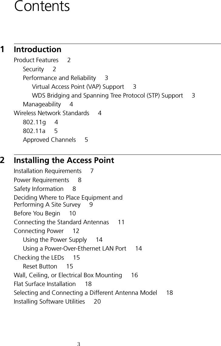

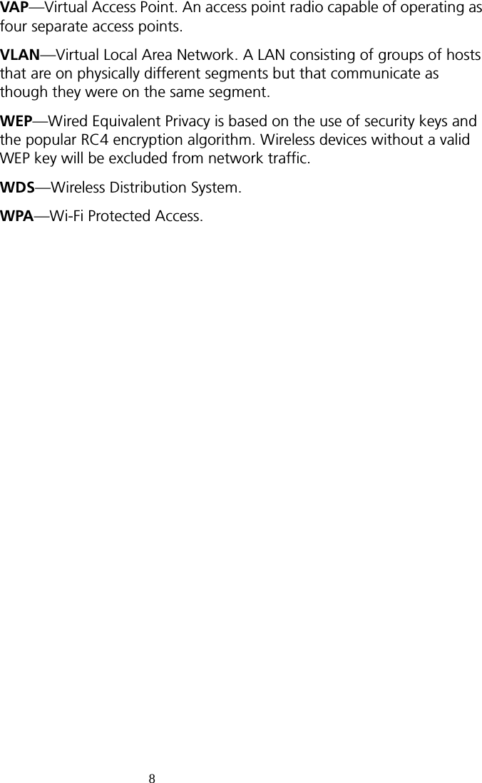
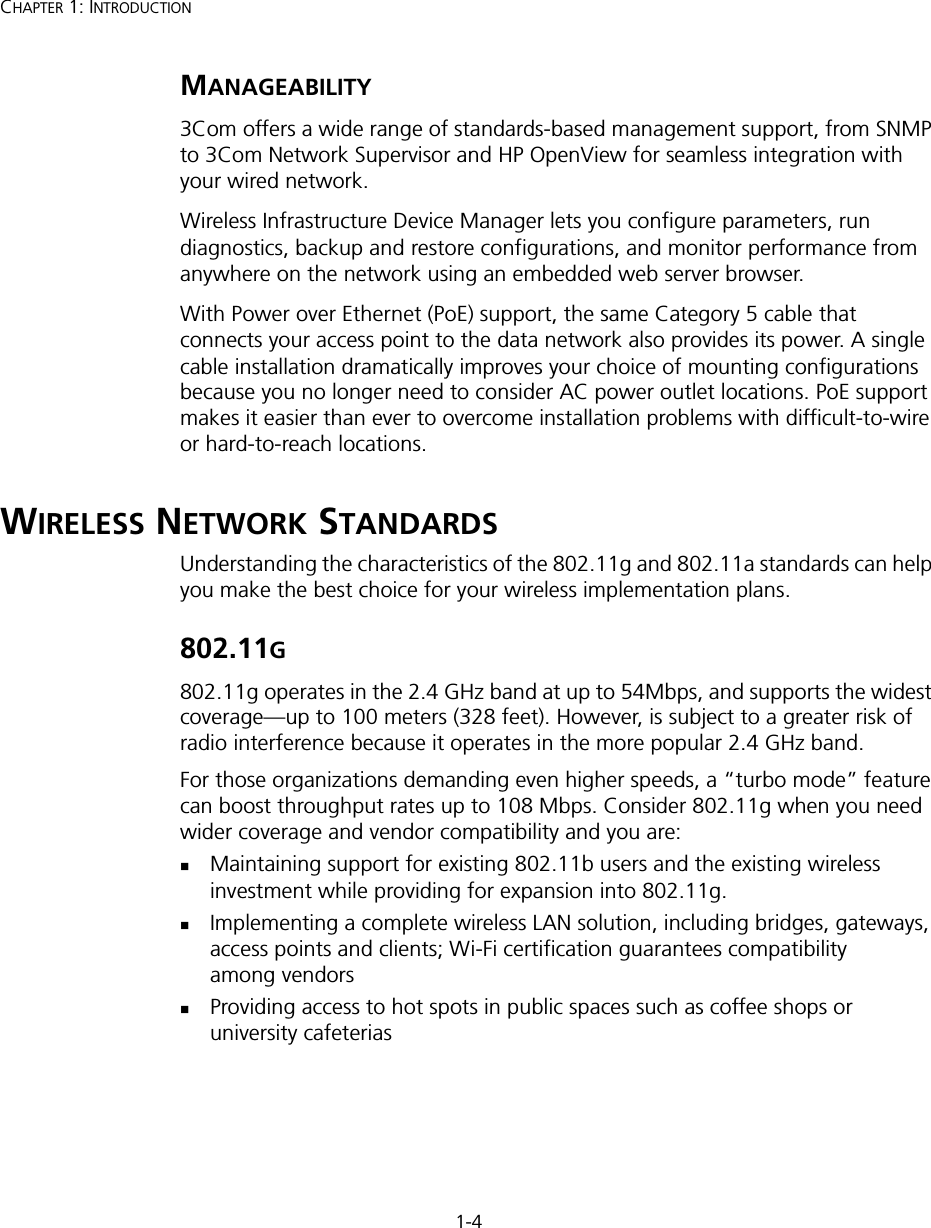

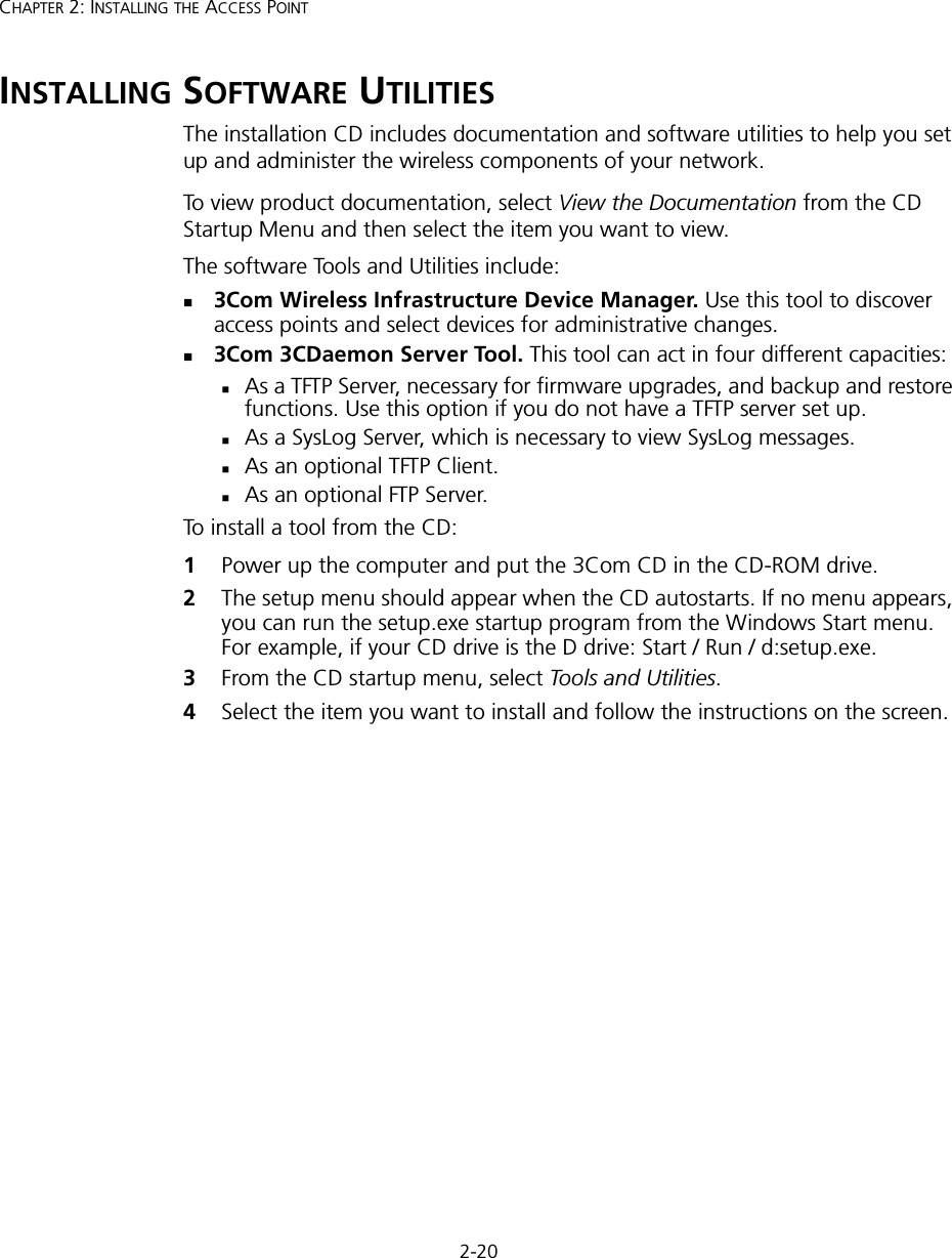

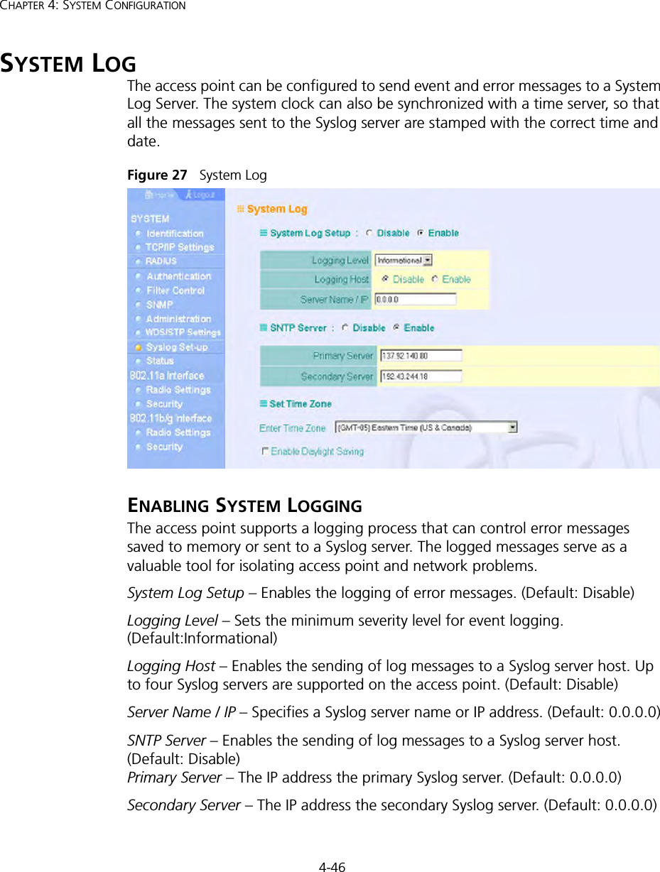
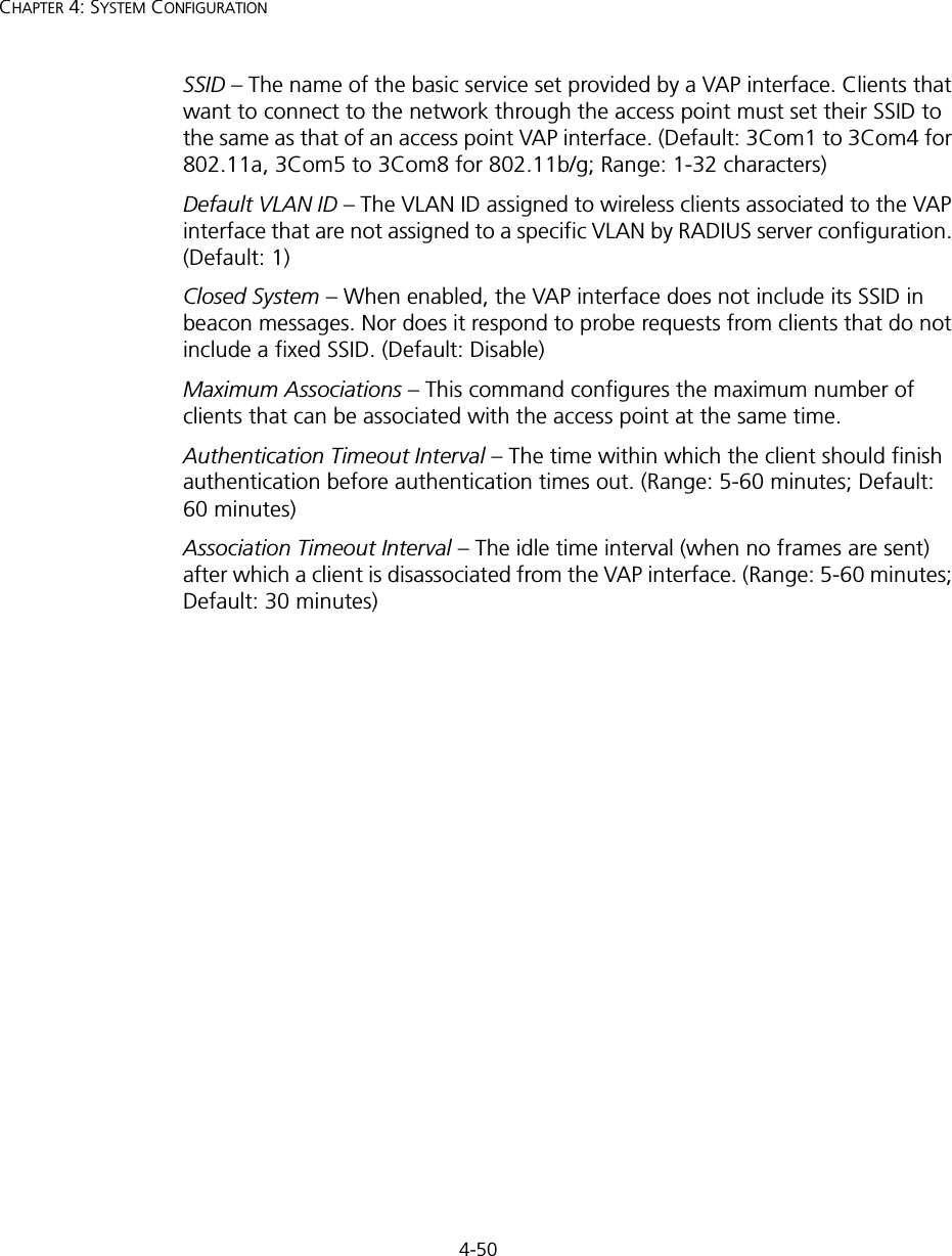
![3-6CHAPTER 3: INITIAL CONFIGURATIONThe home page displays the Main Menu.Figure 4 Home PageLaunching the Setup Wizard – To perform initial configuration, click Setup Wizard on the home page, select the VAP you wish to configure, then click on the [Next] button to start the process. Figure 5 Setup Wizard - Start](https://usermanual.wiki/Hewlett-Packard-Enterprise/WL546.Users-Manual1/User-Guide-670089-Page-34.png)
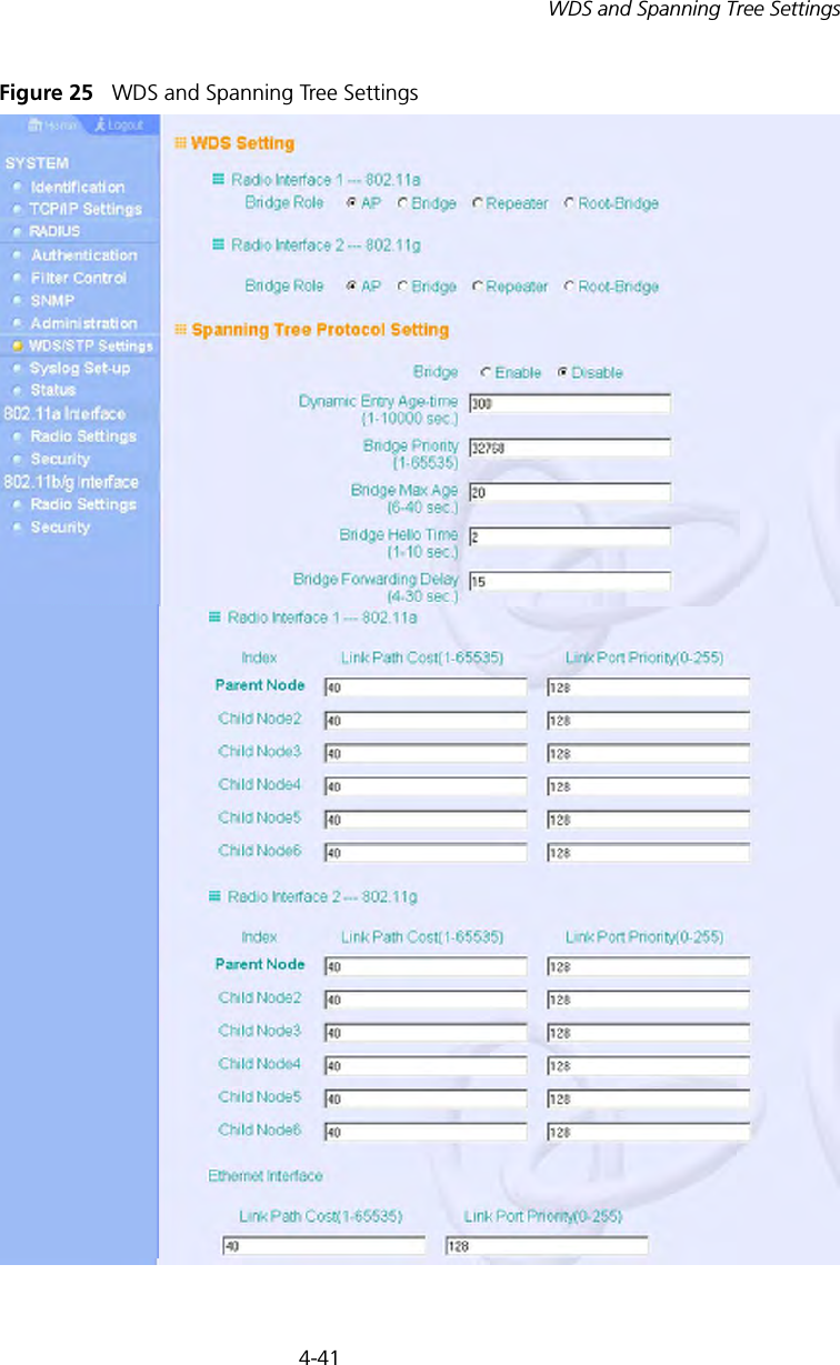
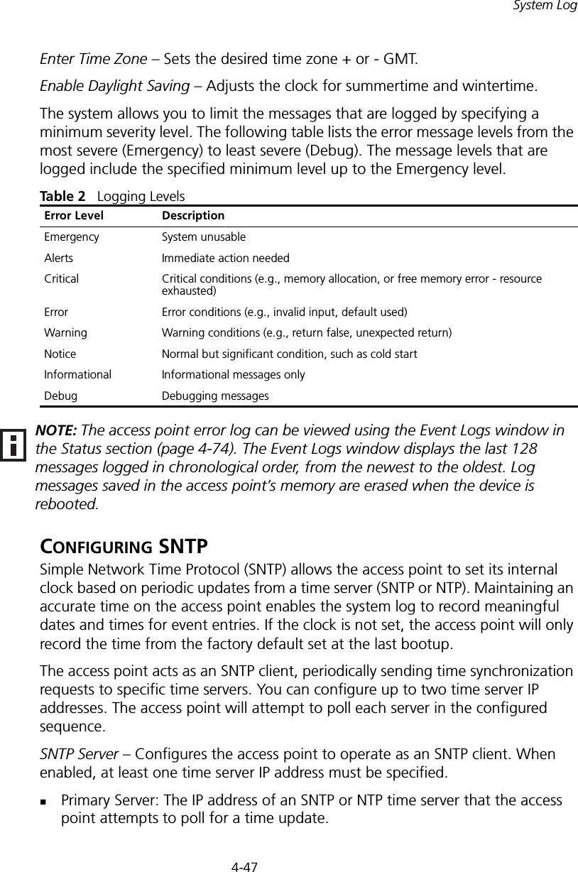
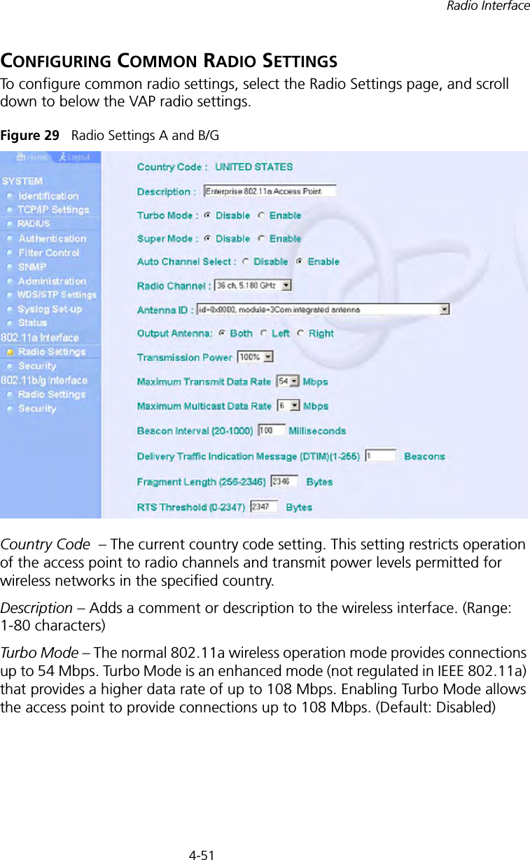
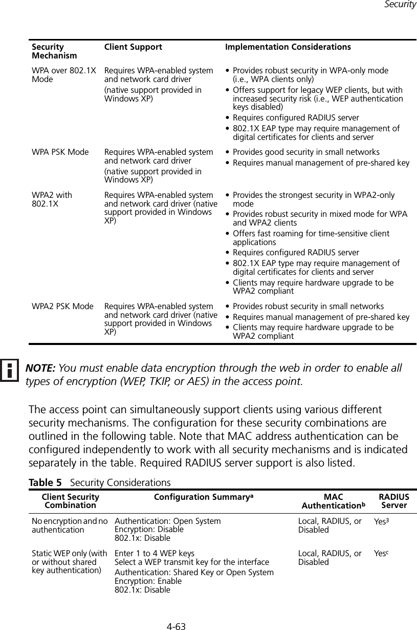
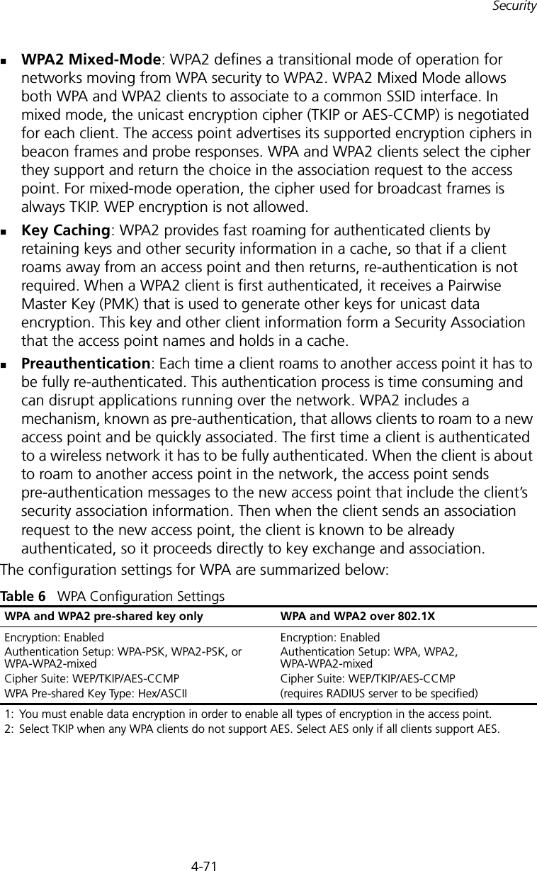
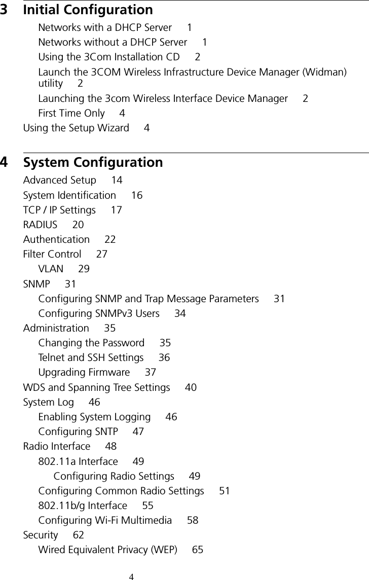
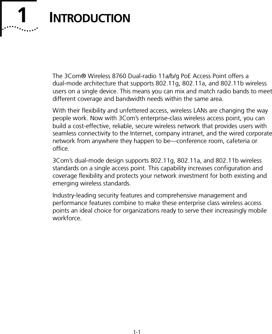
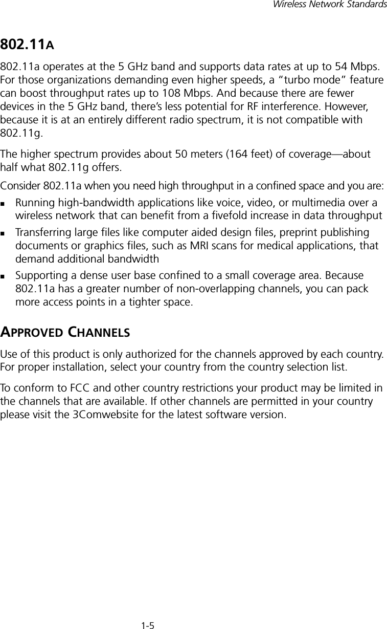
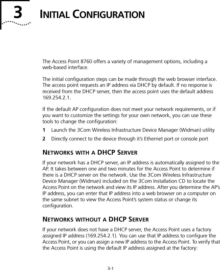
![4-44CHAPTER 4: SYSTEM CONFIGURATIONfrom that device to the root device. Then it selects a designated bridging device from each LAN which incurs the lowest path cost when forwarding a packet from that LAN to the root device. All ports connected to designated bridging devices are assigned as designated ports. After determining the lowest cost spanning tree, it enables all root ports and designated ports, and disables all other ports. Network packets are therefore only forwarded between root ports and designated ports, eliminating any possible network loops.Once a stable network topology has been established, all bridges listen for Hello BPDUs (Bridge Protocol Data Units) transmitted from the root bridge. If a bridge does not get a Hello BPDU after a predefined interval (Maximum Age), the bridge assumes that the link to the root bridge is down. This bridge will then initiate negotiations with other bridges to reconfigure the network to reestablish a valid network topology.Bridge – Enables/disables STP on the wireless bridge or repeater. (Default: Disabled)Bridge Priority – Used in selecting the root device, root port, and designated port. The device with the highest priority becomes the STP root device. However, if all devices have the same priority, the device with the lowest MAC address will then become the root device. (Note that lower numeric values indicate higher priority.)• Range: 0-65535• Default: 32768Bridge Max Age – The maximum time (in seconds) a device can wait without receiving a configuration message before attempting to reconfigure. All device ports (except for designated ports) should receive configuration messages at regular intervals. Any port that ages out STP information (provided in the last configuration message) becomes the designated port for the attached LAN. If it is a root port, a new root port is selected from among the device ports attached to the network. (Range: 6-40 seconds)• Default: 20• Minimum: The higher of 6 or [2 x (Hello Time + 1)].• Maximum: The lower of 40 or [2 x (Forward Delay - 1)]Bridge Hello Time – Interval (in seconds) at which the root device transmits a configuration message. (Range: 1-10 seconds)• Default: 2• Minimum: 1• Maximum: The lower of 10 or [(Max. Message Age / 2) -1]](https://usermanual.wiki/Hewlett-Packard-Enterprise/WL546.Users-Manual1/User-Guide-670089-Page-72.png)
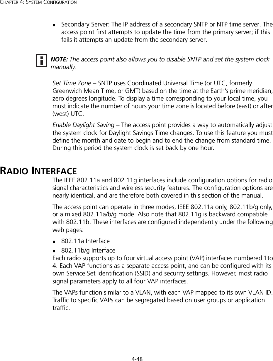
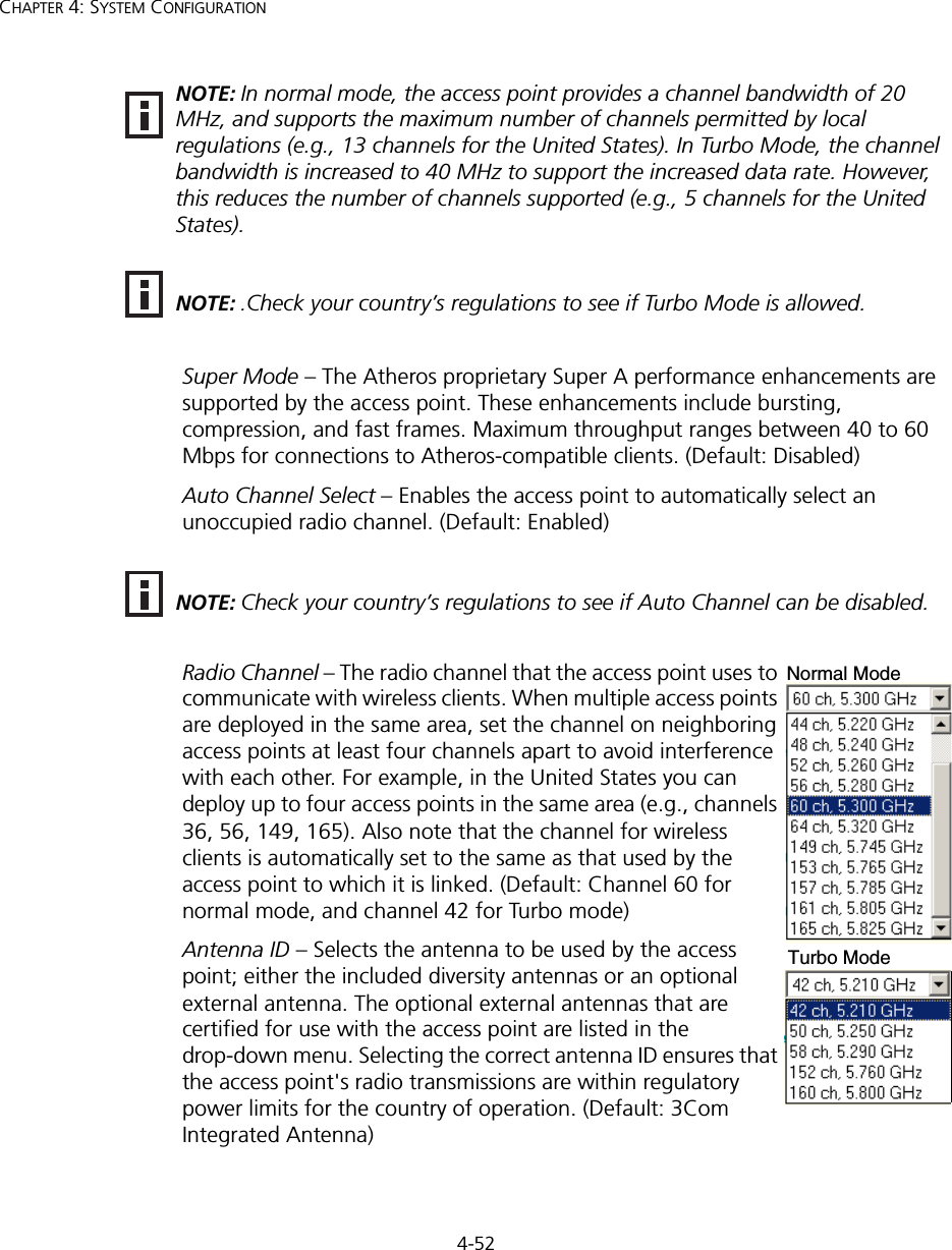
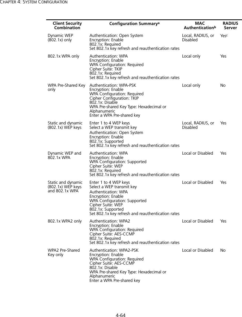
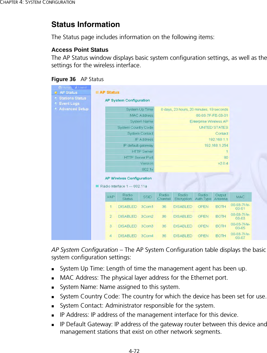
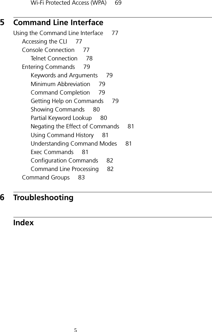
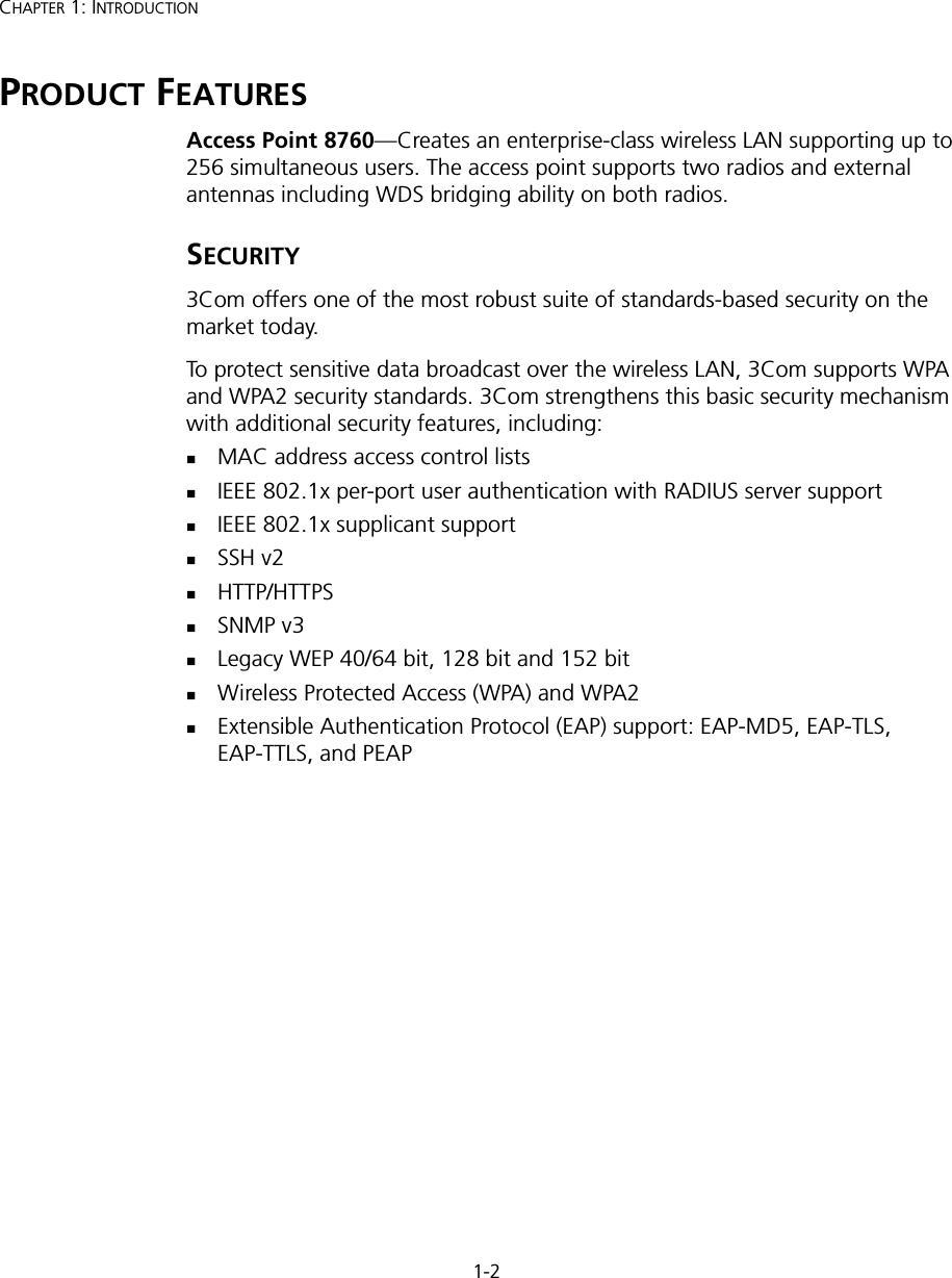
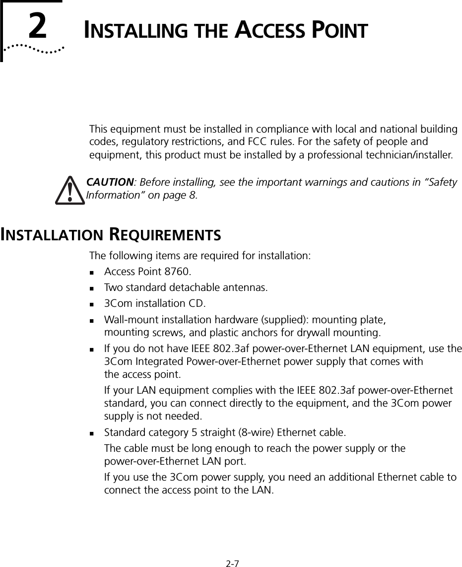
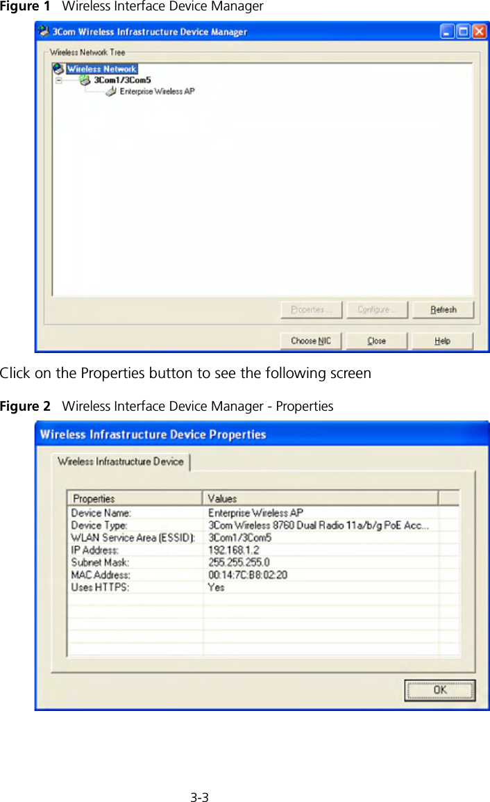
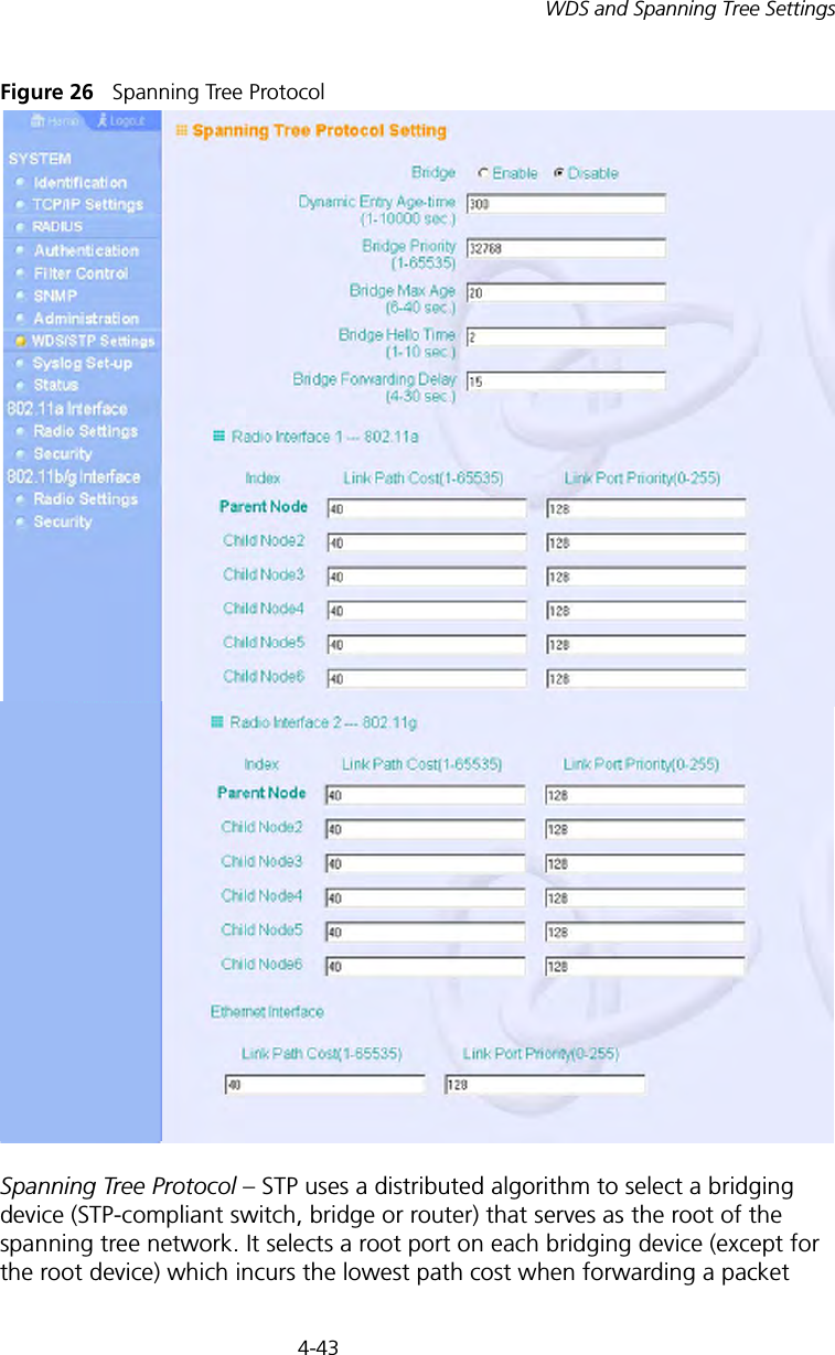
![4-45WDS and Spanning Tree SettingsBridge Forwarding Delay – The maximum time (in seconds) this device waits before changing states (i.e., discarding to learning to forwarding). This delay is required because every device must receive information about topology changes before it starts to forward frames. In addition, each port needs time to listen for conflicting information that would make it return to a discarding state; otherwise, temporary data loops might result. (Range: 4-30 seconds)• Default: 15• Minimum: The higher of 4 or [(Max. Message Age / 2) + 1]• Maximum: 30Link Path Cost – This parameter is used by the STP to determine the best path between devices. Therefore, lower values should be assigned to ports attached to faster media, and higher values assigned to ports with slower media. (Path cost takes precedence over port priority.) • Range: 1-65535• Default: Ethernet interface: 19; Wireless interface: 40Link Port Priority – Defines the priority used for this port in the Spanning Tree Protocol. If the path cost for all ports on a switch are the same, the port with the highest priority (i.e., lowest value) will be configured as an active link in the spanning tree. This makes a port with higher priority less likely to be blocked if the Spanning Tree Protocol is detecting network loops. Where more than one port is assigned the highest priority, the port with lowest numeric identifier will be enabled.• Default: 128• Range: 0-240, in steps of 16](https://usermanual.wiki/Hewlett-Packard-Enterprise/WL546.Users-Manual1/User-Guide-670089-Page-73.png)