Hewlett Packard Enterprise WL546 Wireless 8760 Dual Radio 11a/b/g PoE Access Point User Manual WA6102X 2 32 UG booK
Hewlett-Packard Company Wireless 8760 Dual Radio 11a/b/g PoE Access Point WA6102X 2 32 UG booK
Contents
- 1. Users Manual1
- 2. Users Manual2
Users Manual2

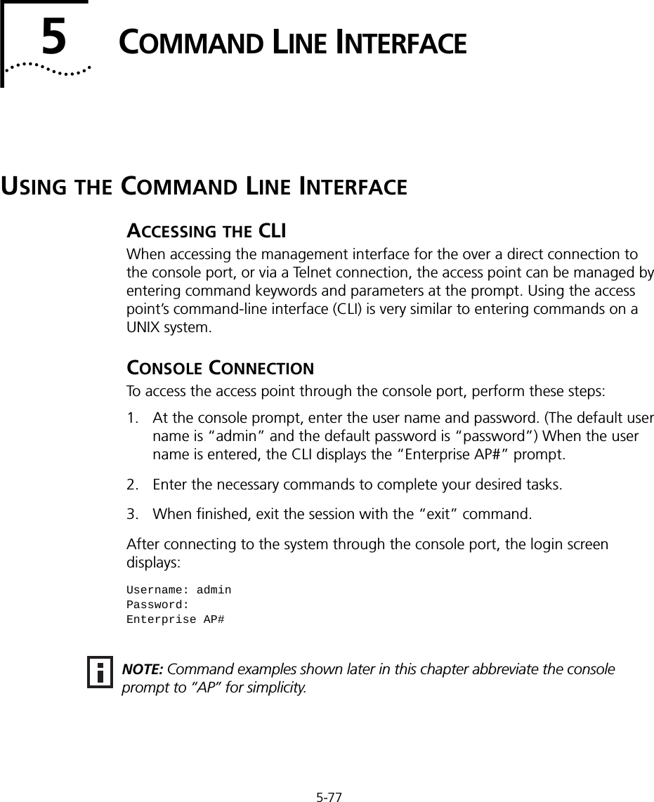
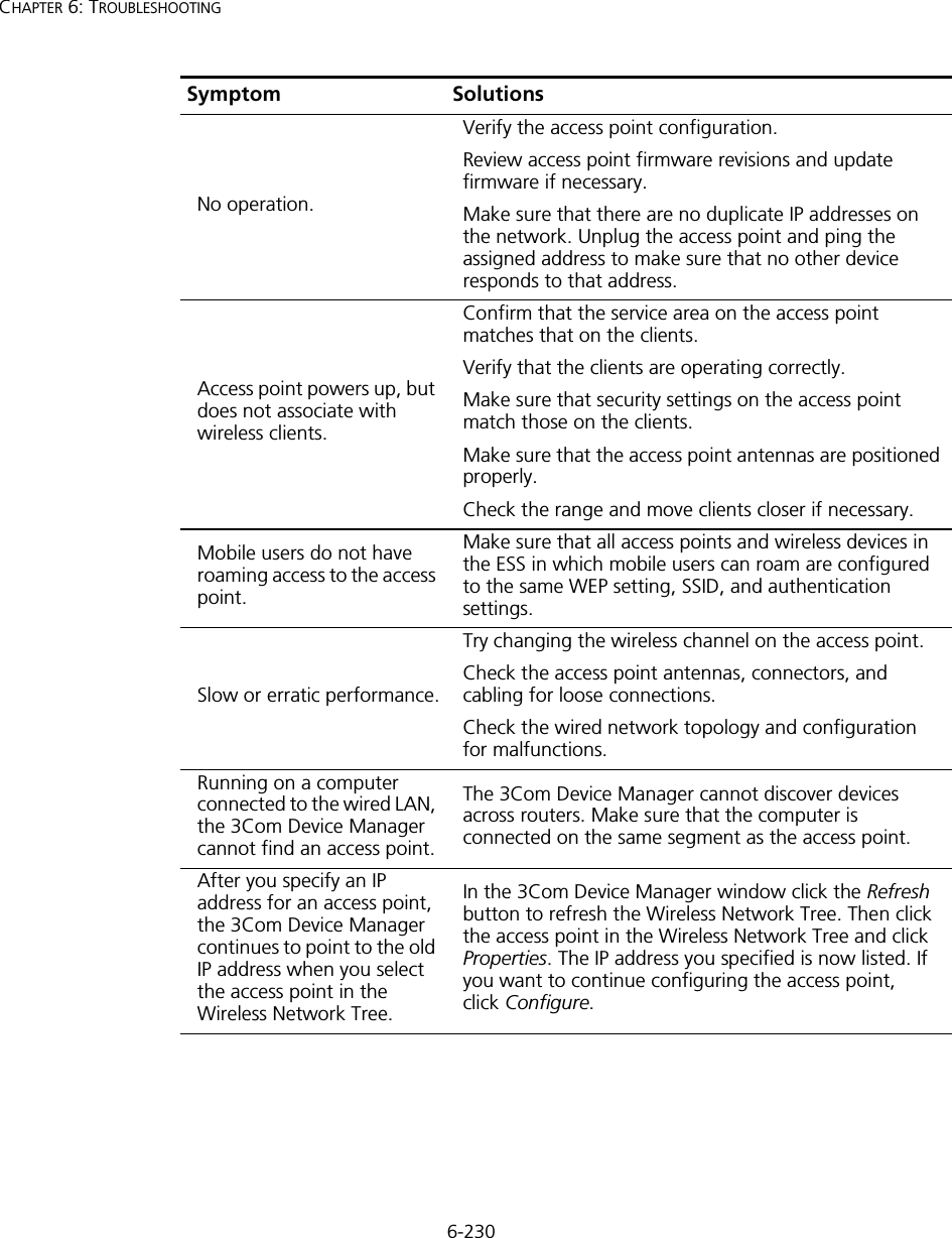
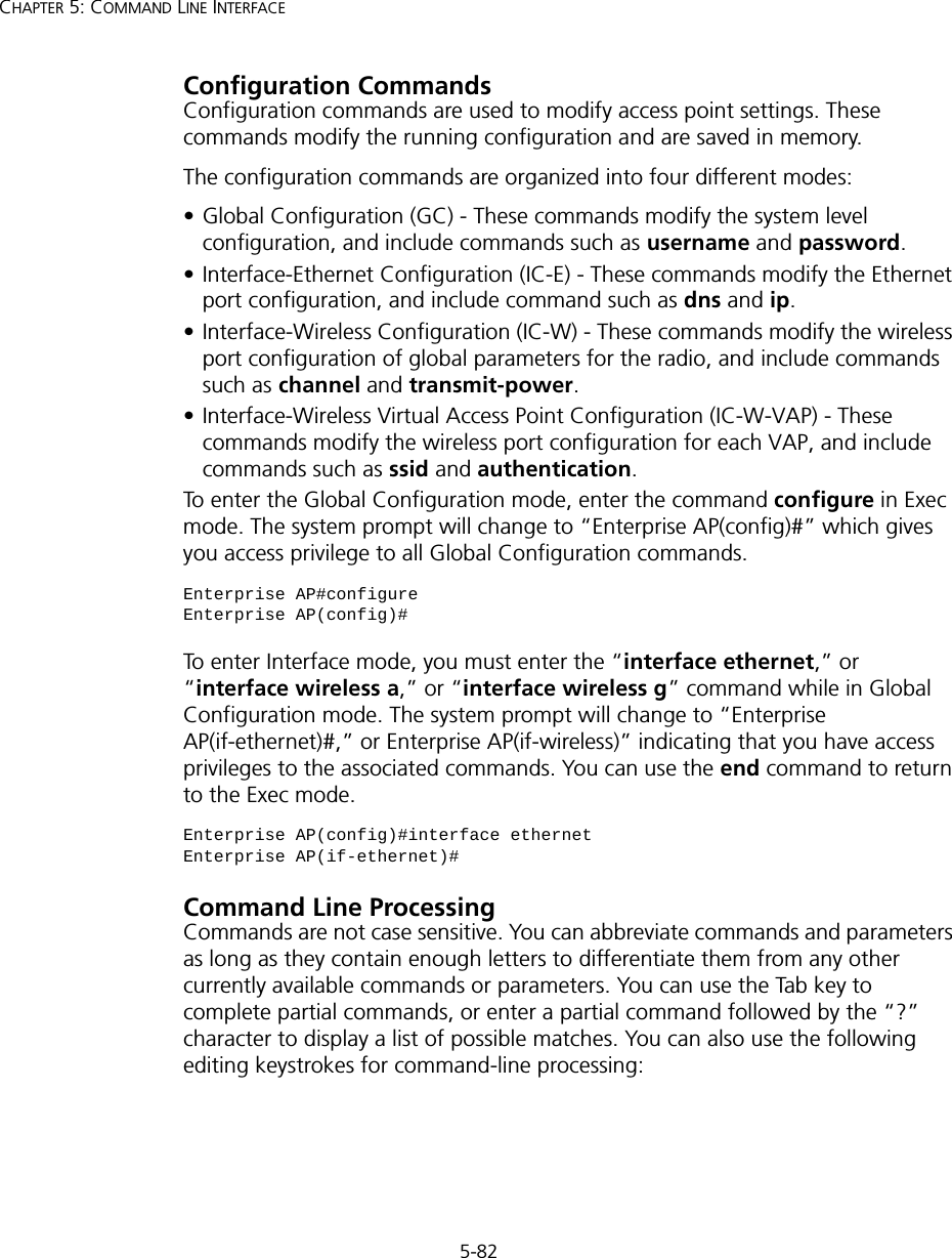
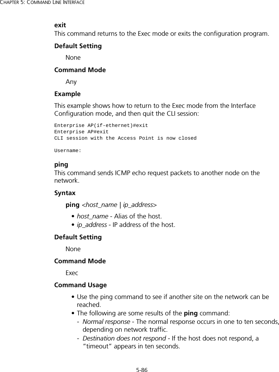
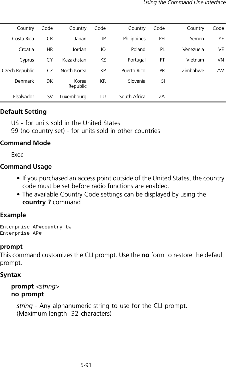
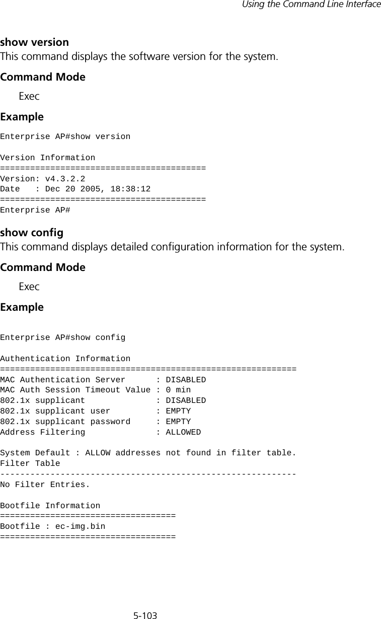
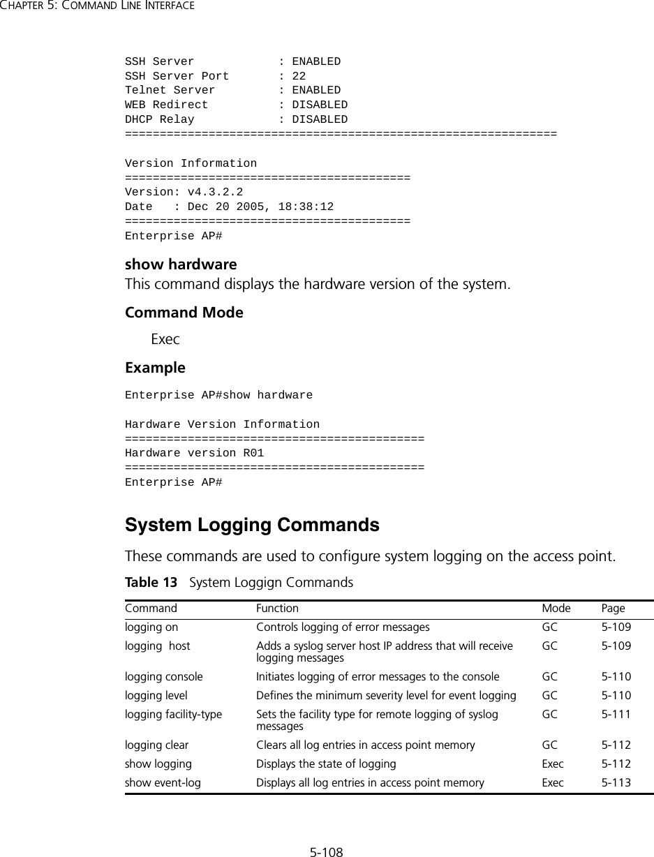
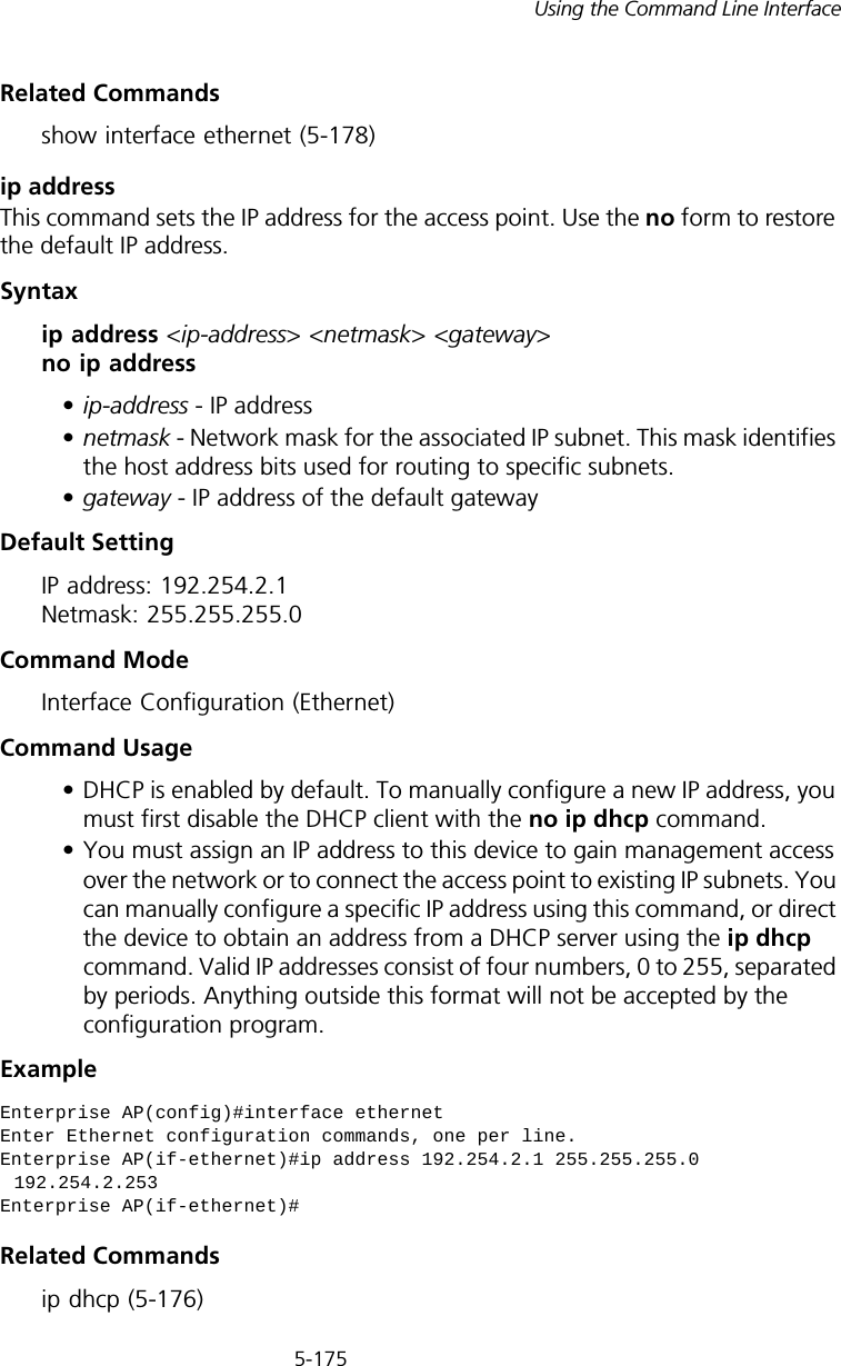
![5-81Using the Command Line InterfaceNegating the Effect of CommandsFor many configuration commands you can enter the prefix keyword “no” to cancel the effect of a command or reset the configuration to the default value. For example, the logging command will log system messages to a host server. To disable logging, specify the no logging command. This guide describes the negation effect for all applicable commands.Using Command HistoryThe CLI maintains a history of commands that have been entered. You can scroll back through the history of commands by pressing the up arrow key. Any command displayed in the history list can be executed again, or first modified and then executed. Using the show history command displays a longer list of recently executed commands. Understanding Command ModesThe command set is divided into Exec and Configuration classes. Exec commands generally display information on system status or clear statistical counters. Configuration commands, on the other hand, modify interface parameters or enable certain functions. These classes are further divided into different modes. Available commands depend on the selected mode. You can always enter a question mark “?” at the prompt to display a list of the commands available for the current mode. The command classes and associated modes are displayed in the following table:Table 7 Command ModesExec CommandsWhen you open a new console session on an access point, the system enters Exec command mode. Only a limited number of the commands are available in this mode. You can access all other commands only from the configuration mode. To access Exec mode, open a new console session with the user name “admin.” The command prompt displays as “Enterprise AP#” for Exec mode. Class ModeExec PrivilegedConfiguration GlobalInterface-ethernetInterface-wirelessInterface-wireless-vapUsername: adminPassword: [system login password]Enterprise AP#](https://usermanual.wiki/Hewlett-Packard-Enterprise/WL546.Users-Manual2/User-Guide-670090-Page-9.png)
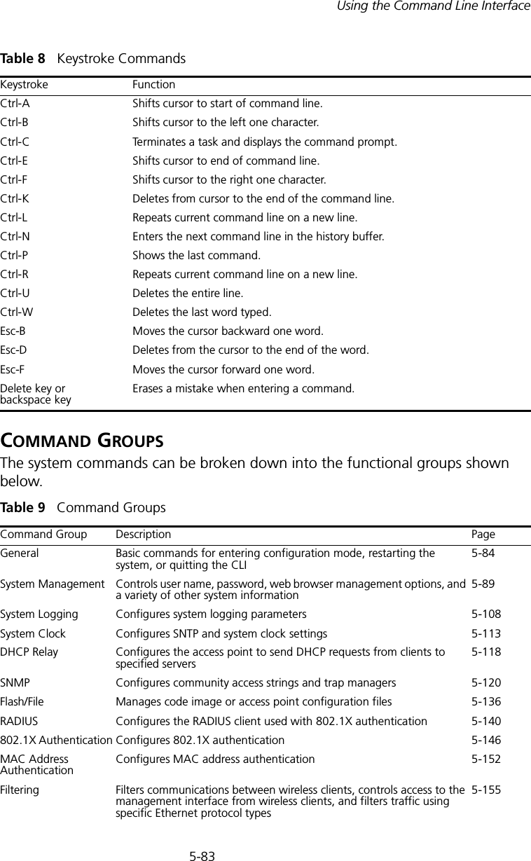
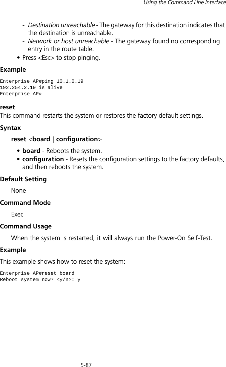

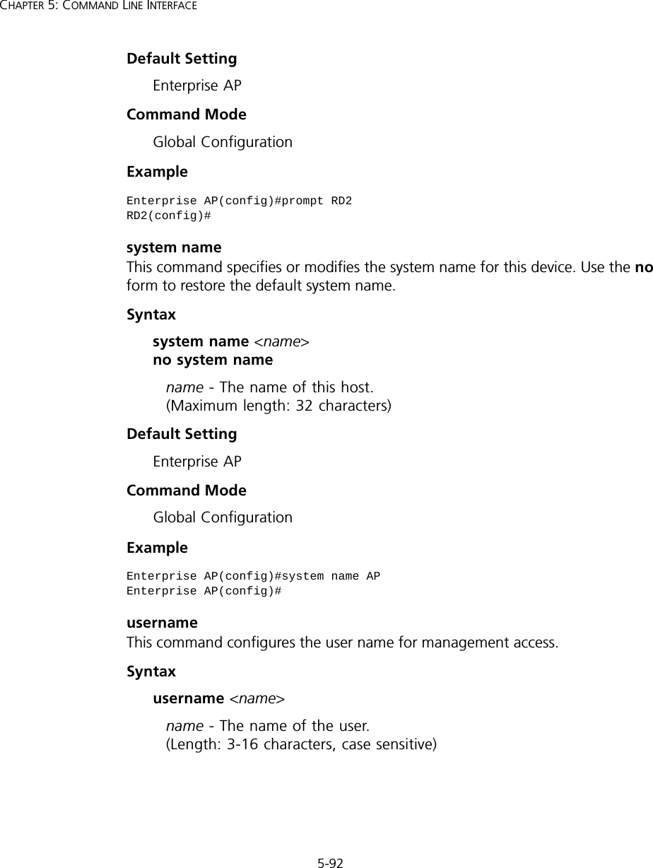
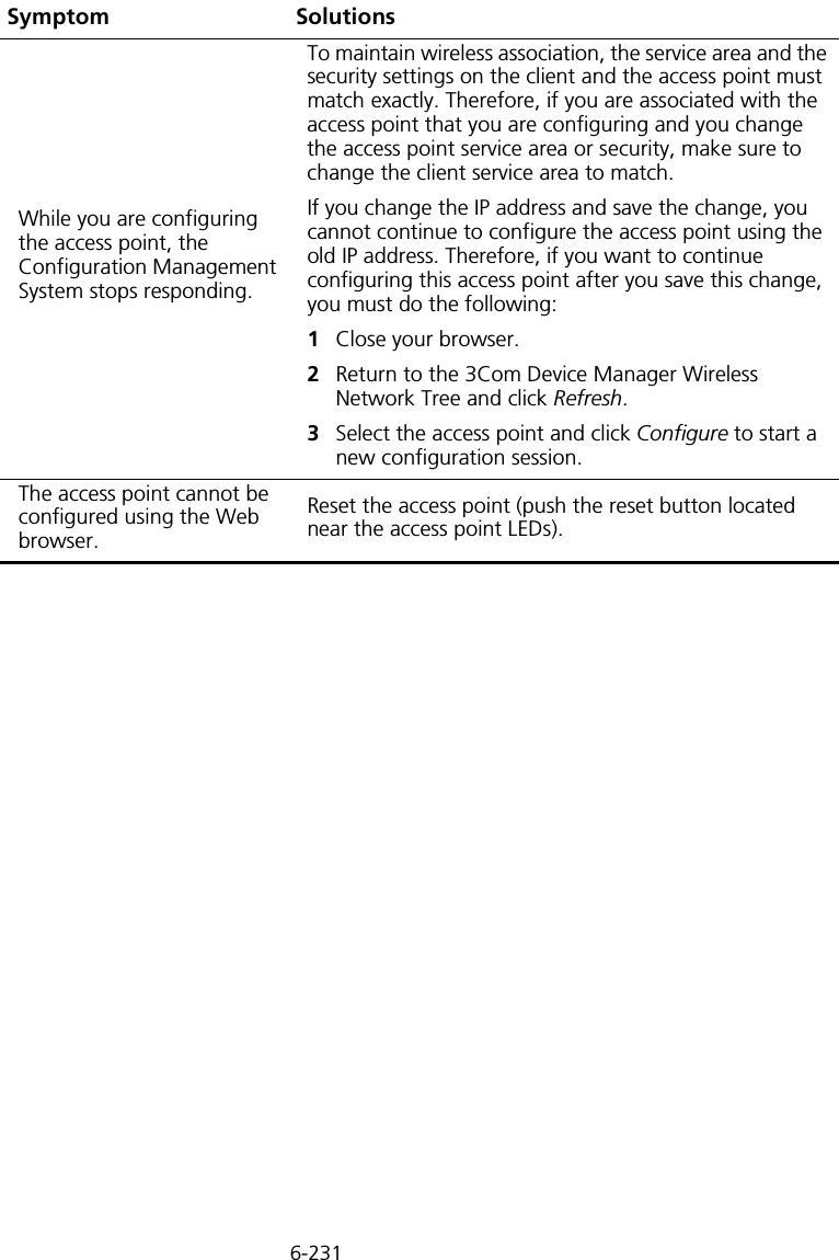
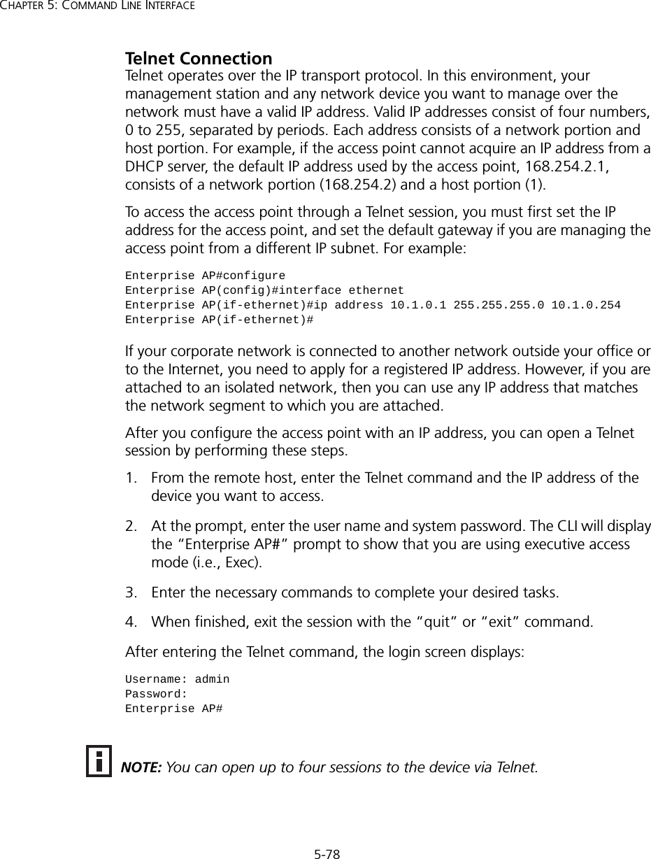
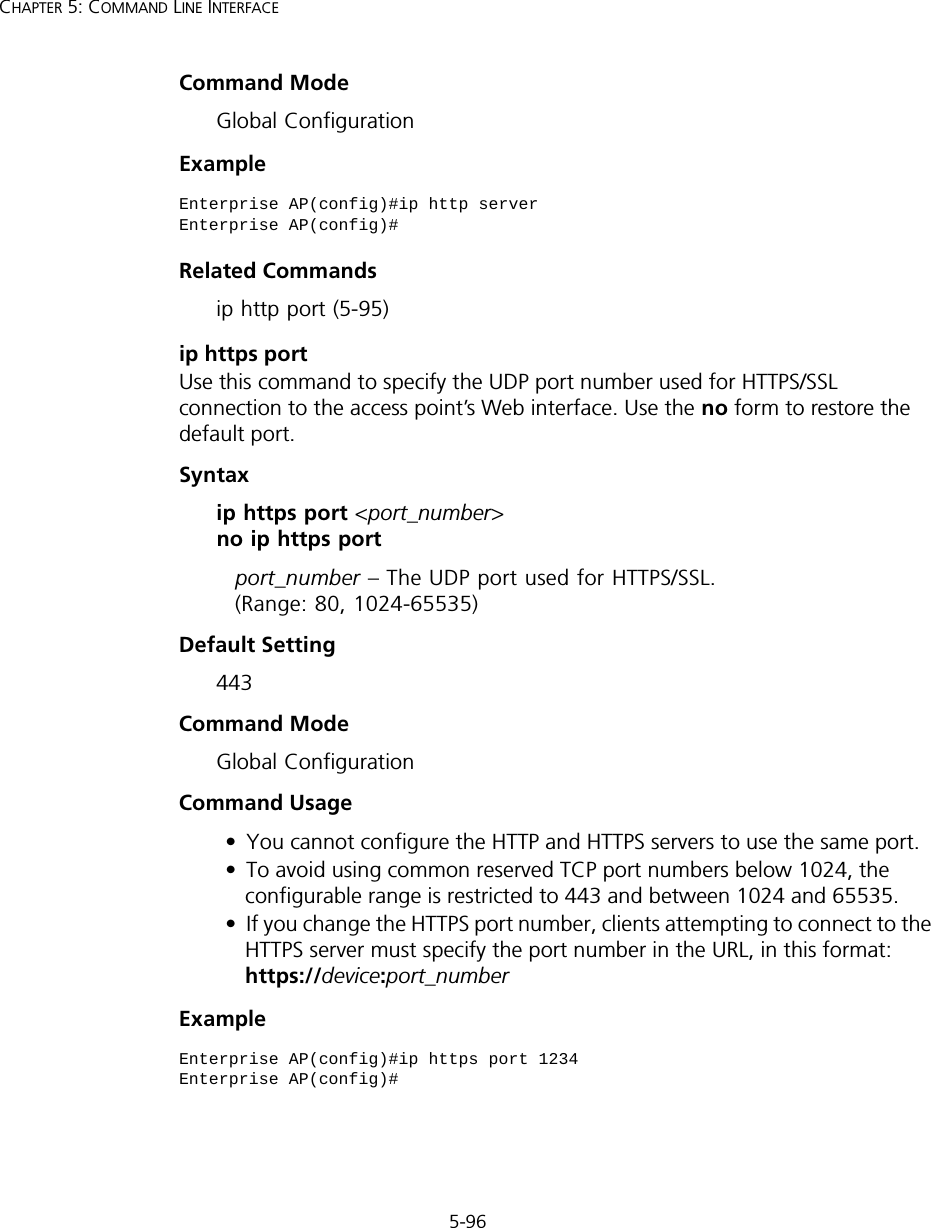
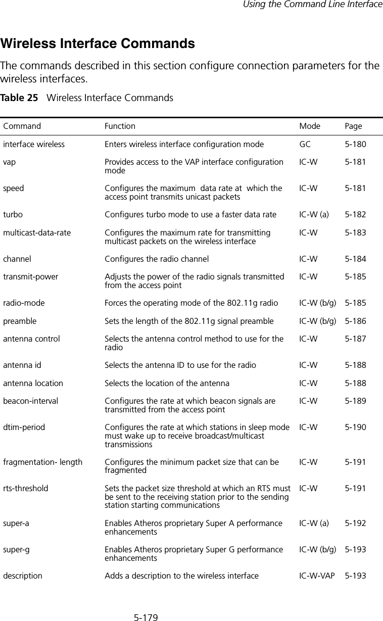
![5-95Using the Command Line InterfaceCommand Mode Interface Configuration (Ethernet)Exampleip http portThis command specifies the TCP port number used by the web browser interface. Use the no form to use the default port.Syntax ip http port <port-number> no ip http portport-number - The TCP port to be used by the browser interface. (Range: 1024-65535)Default Setting 80Command Mode Global ConfigurationExampleRelated Commandsip http server (5-95)ip http serverThis command allows this device to be monitored or configured from a browser. Use the no form to disable this function.Syntax [no] ip http serverDefault Setting EnabledEnterprise AP(if-ethernet)#ip telnet-server enableEnterprise AP(if-ethernet)#Enterprise AP(config)#ip http port 769Enterprise AP(config)#](https://usermanual.wiki/Hewlett-Packard-Enterprise/WL546.Users-Manual2/User-Guide-670090-Page-23.png)
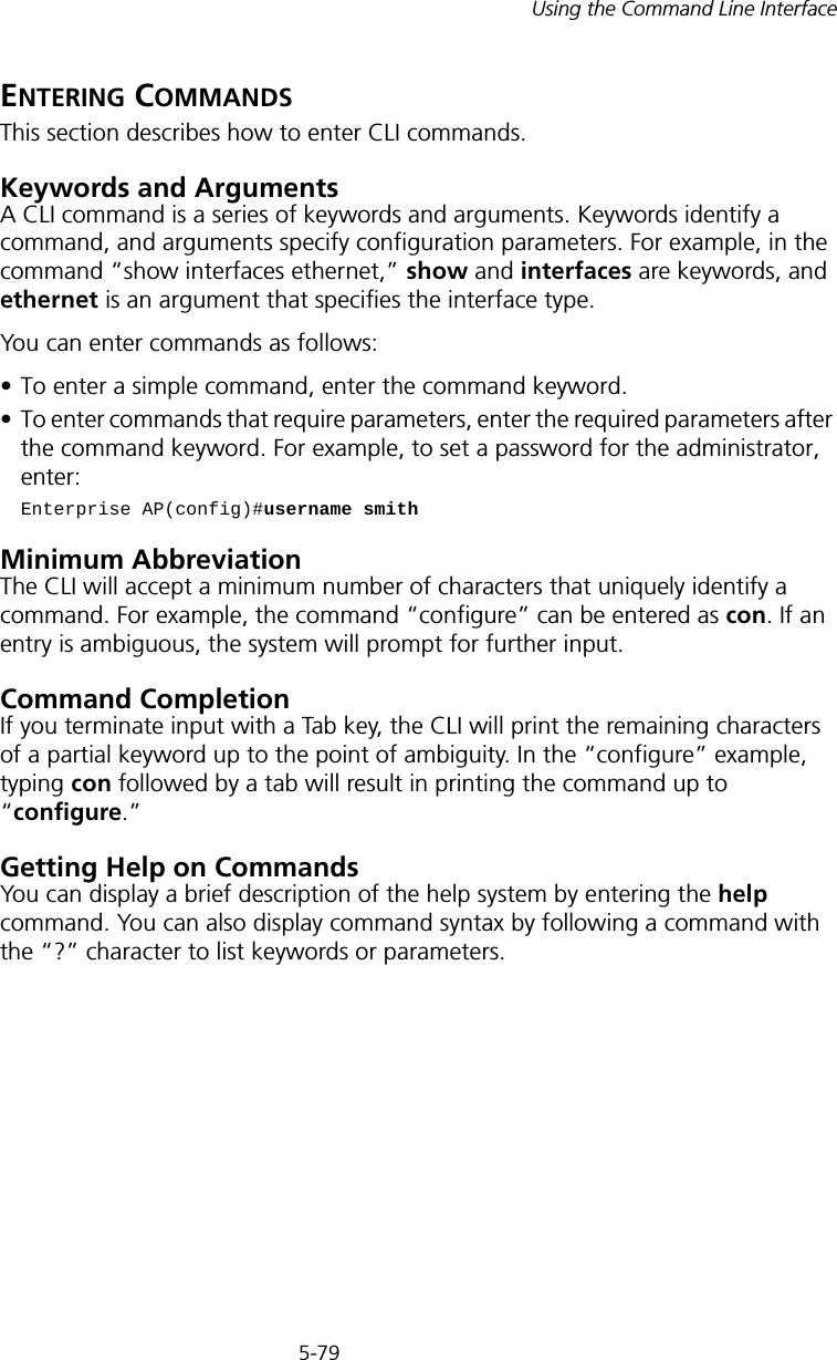
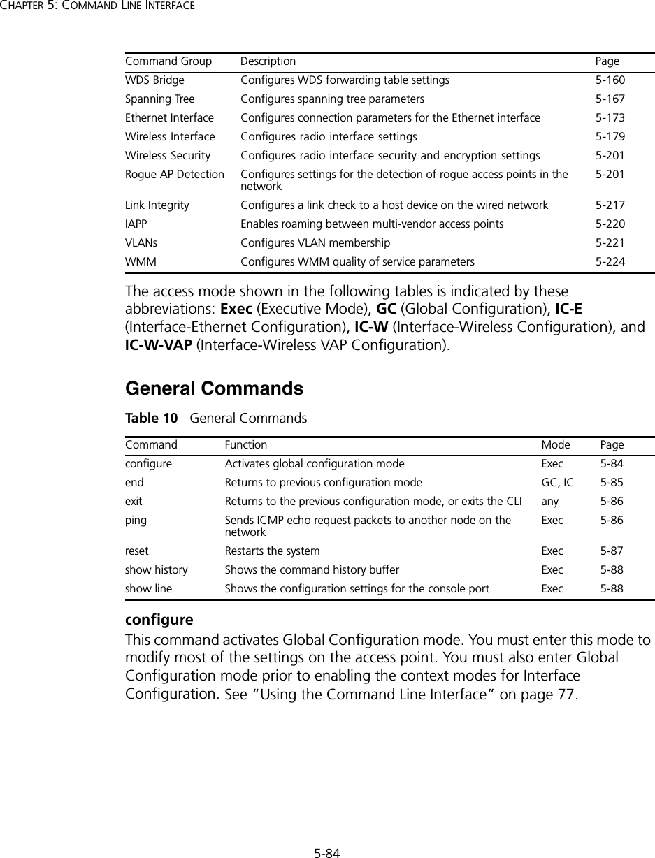
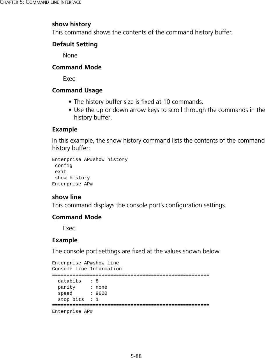
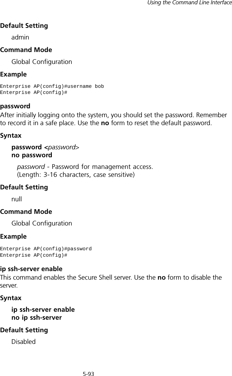
![5-97Using the Command Line Interfaceip https serverUse this command to enable the secure hypertext transfer protocol (HTTPS) over the Secure Socket Layer (SSL), providing secure access (i.e., an encrypted connection) to the access point’s Web interface. Use the no form to disable this function.Syntax [no] ip https serverDefault Setting DisabledCommand Mode Global ConfigurationCommand Usage • Both HTTP and HTTPS service can be enabled independently.• If you enable HTTPS, you must indicate this in the URL: https://device:port_number]• When you start HTTPS, the connection is established in this way:- The client authenticates the server using the server’s digital certificate.- The client and server negotiate a set of security protocols to use for the connection.- The client and server generate session keys for encrypting and decrypting data.• The client and server establish a secure encrypted connection. A padlock icon should appear in the status bar for Internet Explorer 5.x.Example Enterprise AP(config)#ip https serverEnterprise AP(config)#](https://usermanual.wiki/Hewlett-Packard-Enterprise/WL546.Users-Manual2/User-Guide-670090-Page-25.png)
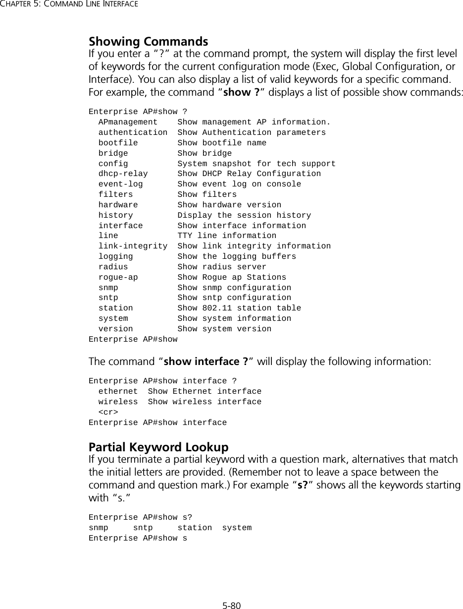
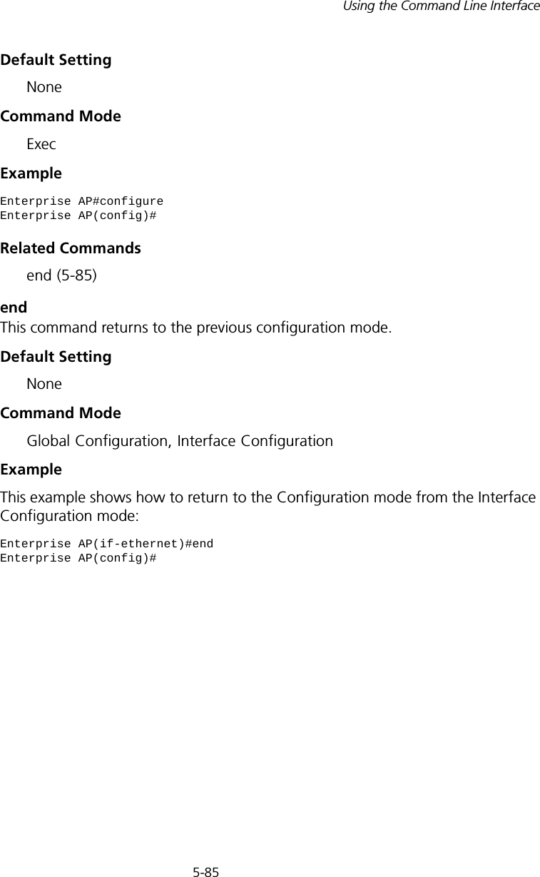
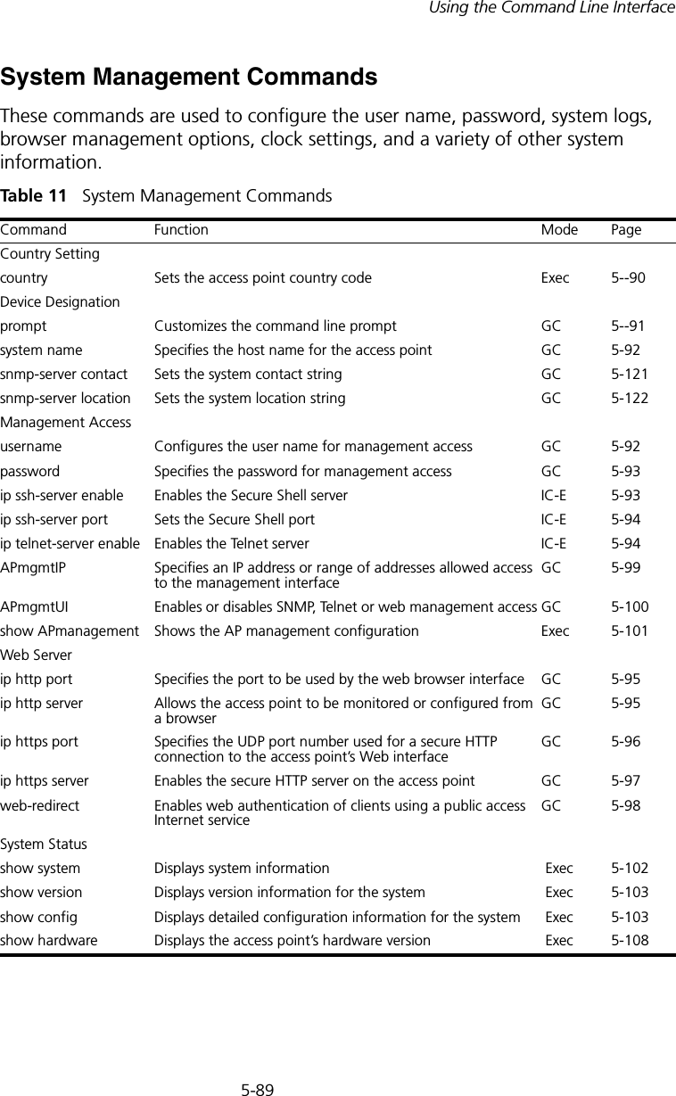
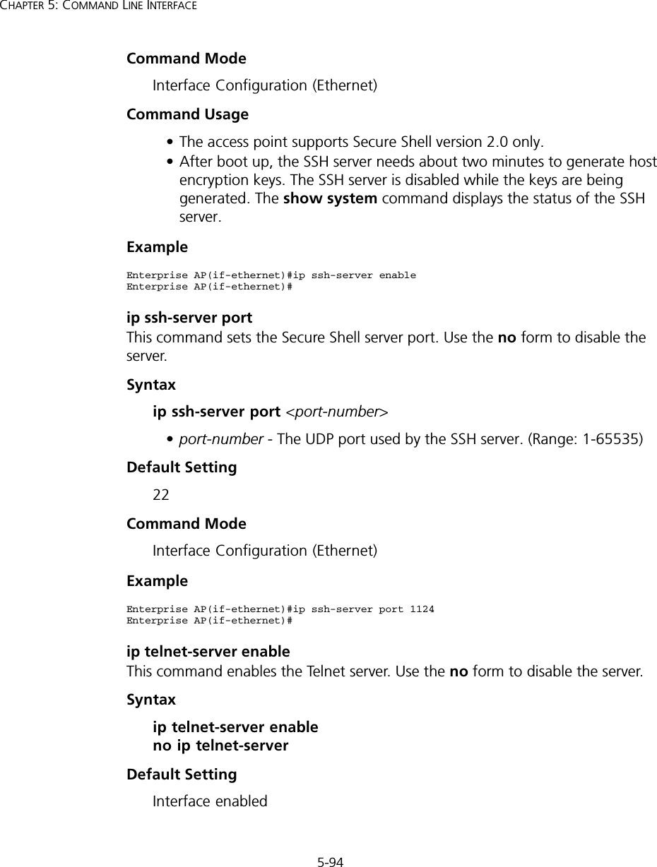
![5-98CHAPTER 5: COMMAND LINE INTERFACEweb-redirectUse this command to enable web-based authentication of clients. Use the no form to disable this function.Syntax [no] web-redirectDefault Setting DisabledCommand Mode Global ConfigurationCommand Usage • The web redirect feature is used to support billing for a public access wireless network. After successful association to an access point, a client is “redirected” to an access point login web page as soon as Internet access is attempted. The client is then authenticated by entering a user name and password on the web page. This process allows controlled access for clients without requiring 802.1X or MAC authentication.• Web redirect requires a RADIUS server on the wired network with configured user names and passwords for authentication. The RADIUS server details must also be configured on the access point. (See “show bootfile” on page 140.)•Use the show system command to display the current web redirect status.Example Enterprise AP(config)#web-redirectEnterprise AP(config)#](https://usermanual.wiki/Hewlett-Packard-Enterprise/WL546.Users-Manual2/User-Guide-670090-Page-26.png)
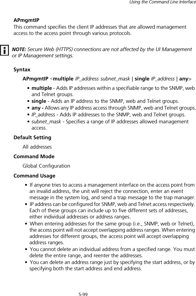
![5-100CHAPTER 5: COMMAND LINE INTERFACEExampleThis example restricts management access to the indicated addresses.APmgmtUIThis command enables and disables management access to the access point through SNMP, Telnet and web interfaces.SyntaxAPmgmtUI <[SNMP | Te l net | Web] enable | disable>•SNMP - Specifies SNMP management access.•Telnet - Specifies Telnet management access.•Web - Specifies web based management access.-enable/disable - Enables or disables the selected management access method.Default SettingAll enabledCommand ModeGlobal ConfigurationExampleThis example restricts management access to the indicated addresses.Enterprise AP(config)#apmgmtip multiple 192.254.1.50 255.255.255.0Enterprise AP(config)#NOTE: Secure Web (HTTPS) connections are not affected by the UI Management or IP Management settings.Enterprise AP(config)#apmgmtui SNMP enableEnterprise AP(config)#](https://usermanual.wiki/Hewlett-Packard-Enterprise/WL546.Users-Manual2/User-Guide-670090-Page-28.png)
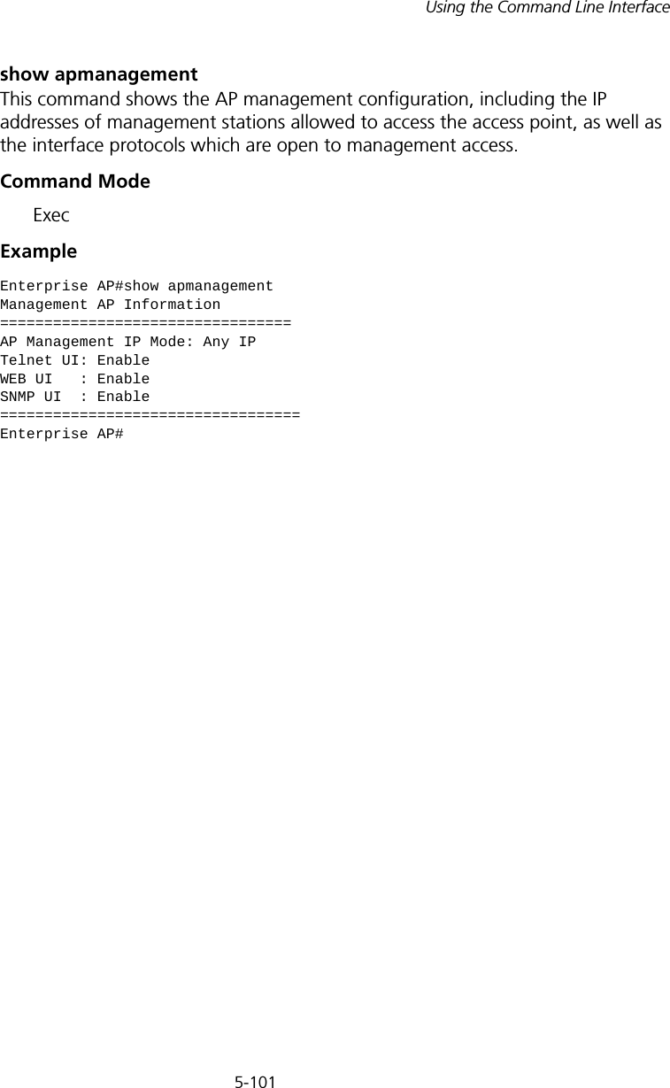
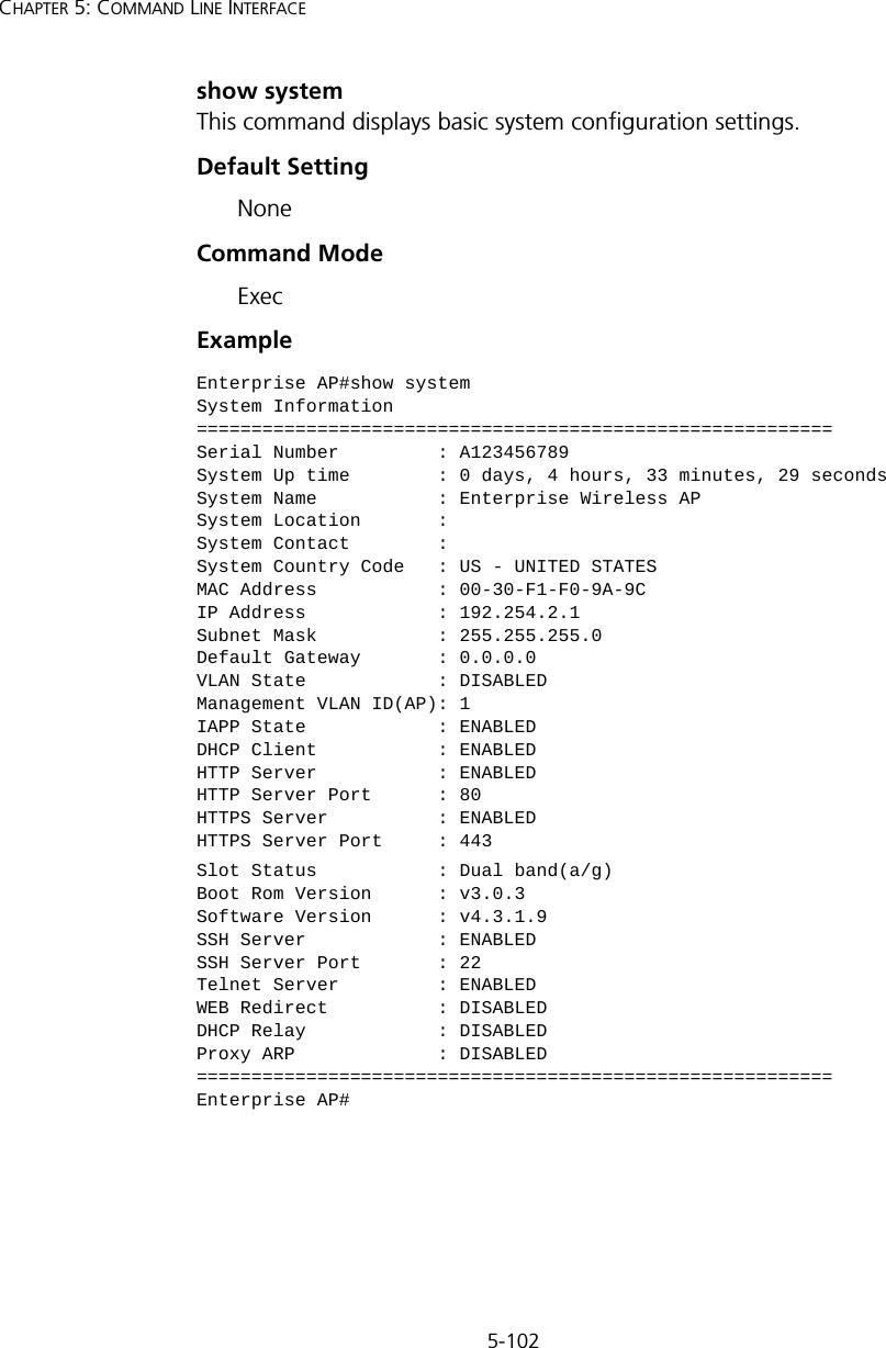
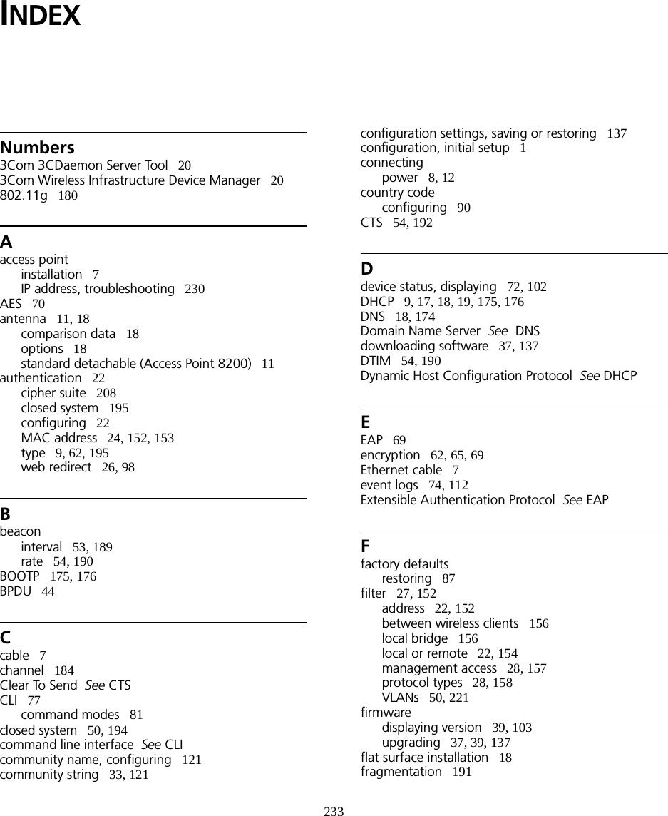
![5-107Using the Command Line InterfaceSNTP Information===========================================================Service State : DisabledSNTP (server 1) IP : 137.92.140.80SNTP (server 2) IP : 192.43.244.18Current Time : 00 : 14, Jan 1st, 1970Time Zone : -5 (BOGOTA, EASTERN, INDIANA)Daylight Saving : Disabled===========================================================Station Table Information===========================================================if-wireless A VAP [0] : 802.11a Channel : AutoNo 802.11a Channel Stations....if-wireless G VAP [0] : 802.11g Channel : AutoNo 802.11g Channel Stations....System Information==============================================================Serial Number : System Up time : 0 days, 0 hours, 16 minutes, 51 secondsSystem Name : Enterprise Wireless APSystem Location : System Contact : ContactSystem Country Code : 99 - NO_COUNTRY_SET MAC Address : 00-12-CF-05-B7-84IP Address : 192.254.0.151Subnet Mask : 255.255.255.0Default Gateway : 192.254.0.1VLAN State : DISABLEDManagement VLAN ID(AP): 1IAPP State : ENABLEDDHCP Client : ENABLEDHTTP Server : ENABLEDHTTP Server Port : 80HTTPS Server : ENABLEDHTTPS Server Port : 443Slot Status : Dual band(a/g)Boot Rom Version : v3.0.7Software Version : v4.3.2.2](https://usermanual.wiki/Hewlett-Packard-Enterprise/WL546.Users-Manual2/User-Guide-670090-Page-35.png)
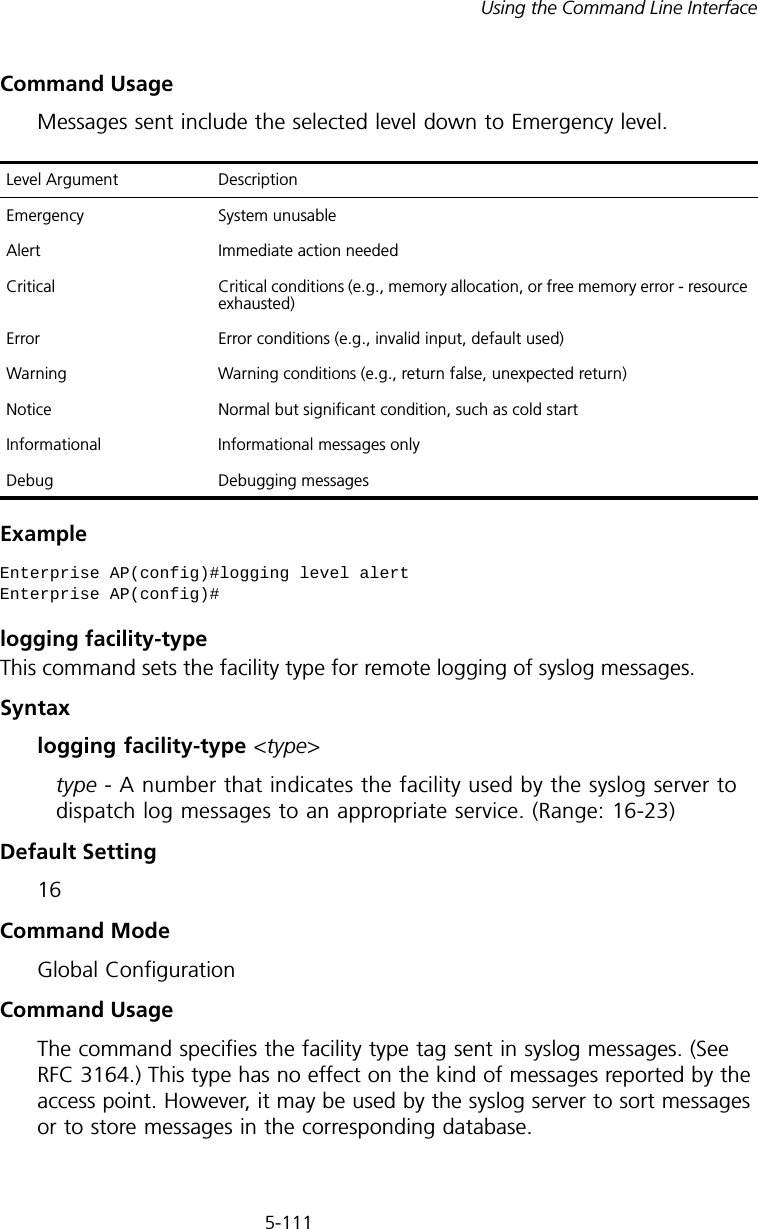
![5-109Using the Command Line Interfacelogging onThis command controls logging of error messages; i.e., sending debug or error messages to memory. The no form disables the logging process.Syntax[no] logging onDefault SettingDisabledCommand Mode Global ConfigurationCommand Usage The logging process controls error messages saved to memory. You can use the logging level command to control the type of error messages that are stored in memory. Example logging hostThis command specifies syslog servers host that will receive logging messages. Use the no form to remove syslog server host.Syntaxlogging host <1 | 2 | 3 | 4> <host_name | host_ip_address> [udp_port] no logging host <1 | 2 | 3 | 4>•1 - First syslog server.•2 - Second syslog server.•3 - Third syslog server.•4 - Fourth syslog server.•host_name - The name of a syslog server. (Range: 1-20 characters)•host_ip_address - The IP address of a syslog server.•udp_port - The UDP port used by the syslog server.Enterprise AP(config)#logging onEnterprise AP(config)#](https://usermanual.wiki/Hewlett-Packard-Enterprise/WL546.Users-Manual2/User-Guide-670090-Page-37.png)
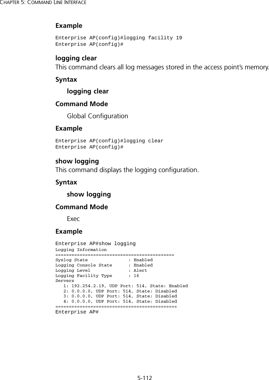
![5-110CHAPTER 5: COMMAND LINE INTERFACEDefault Setting NoneCommand Mode Global ConfigurationExample logging consoleThis command initiates logging of error messages to the console. Use the no form to disable logging to the console.Syntax[no] logging consoleDefault Setting DisabledCommand Mode Global ConfigurationExample logging levelThis command sets the minimum severity level for event logging.Syntaxlogging level <Emergency | Alert | Critical | Error | Warning | Notice | Informational | Debug>Default Setting InformationalCommand Mode Global ConfigurationEnterprise AP(config)#logging host 1 10.1.0.3Enterprise AP(config)#Enterprise AP(config)#logging consoleEnterprise AP(config)#](https://usermanual.wiki/Hewlett-Packard-Enterprise/WL546.Users-Manual2/User-Guide-670090-Page-38.png)
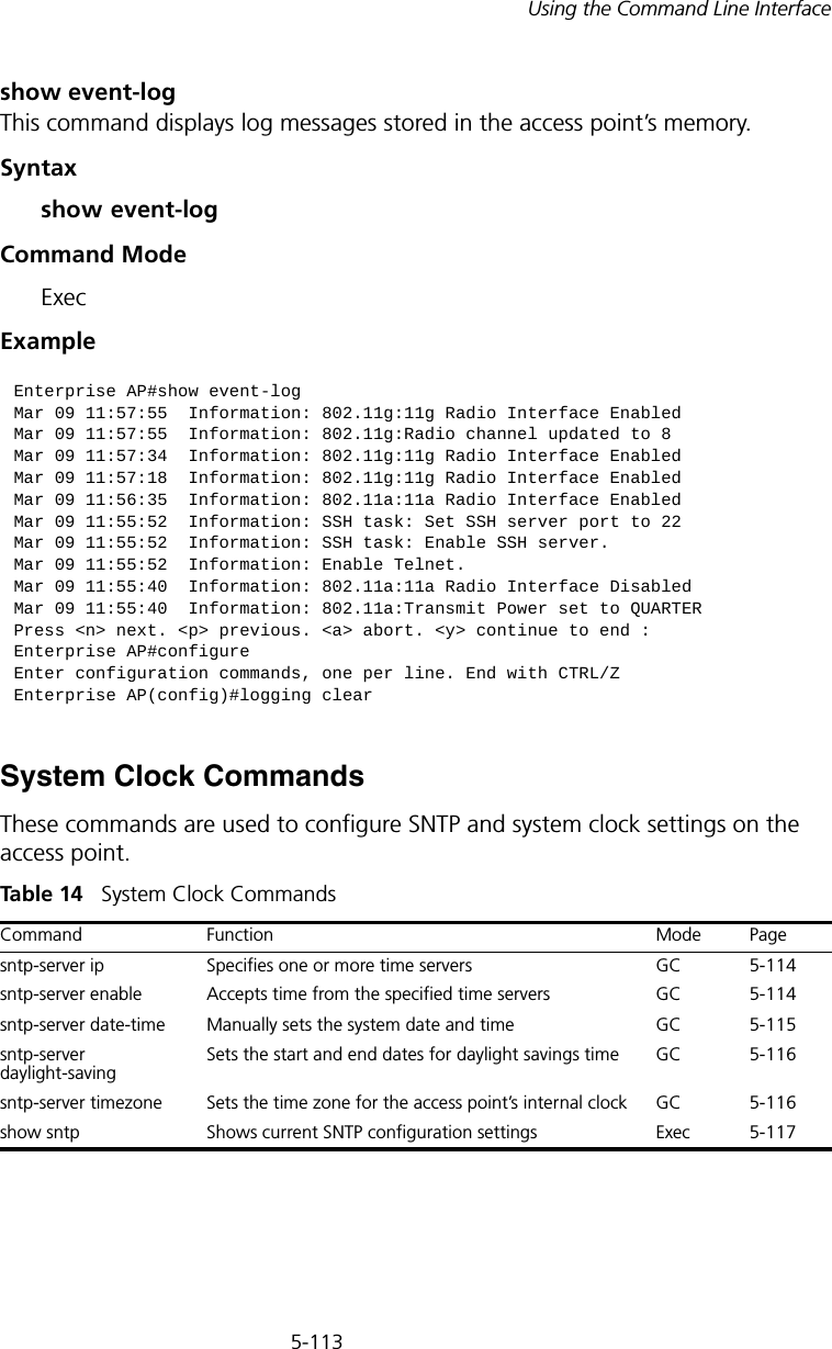
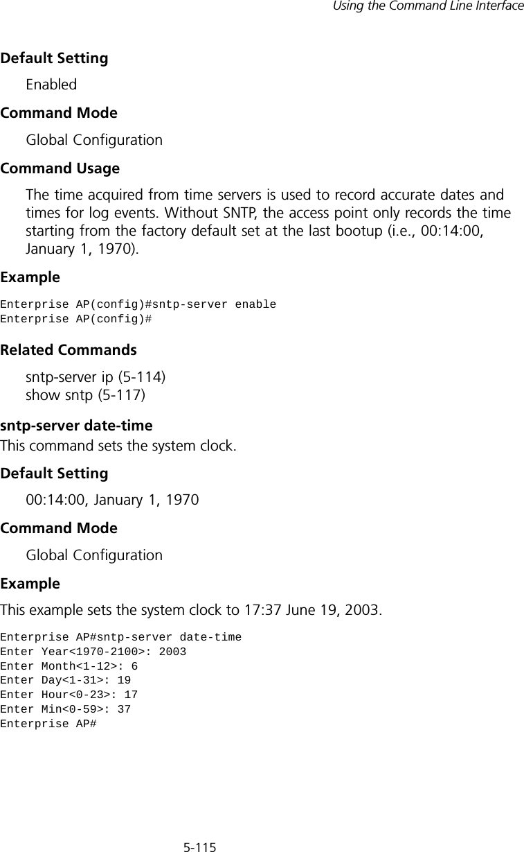
![5-114CHAPTER 5: COMMAND LINE INTERFACEsntp-server ipThis command sets the IP address of the servers to which SNTP time requests are issued. Use the this command with no arguments to clear all time servers from the current list.Syntaxsntp-server ip <1 | 2> <ip>•1 - First time server.•2 - Second time server.•ip - IP address of an time server (NTP or SNTP). Default Setting 137.92.140.80 192.43.244.18Command Mode Global ConfigurationCommand Usage When SNTP client mode is enabled using the sntp-server enable command, the sntp-server ip command specifies the time servers from which the access point polls for time updates. The access point will poll the time servers in the order specified until a response is received. Example Related Commandssntp-server enable (5-114) show sntp (5-117)sntp-server enableThis command enables SNTP client requests for time synchronization with NTP or SNTP time servers specified by the sntp-server ip command. Use the no form to disable SNTP client requests.Syntax[no] sntp-server enable Enterprise AP(config)#sntp-server ip 10.1.0.19Enterprise AP#](https://usermanual.wiki/Hewlett-Packard-Enterprise/WL546.Users-Manual2/User-Guide-670090-Page-42.png)
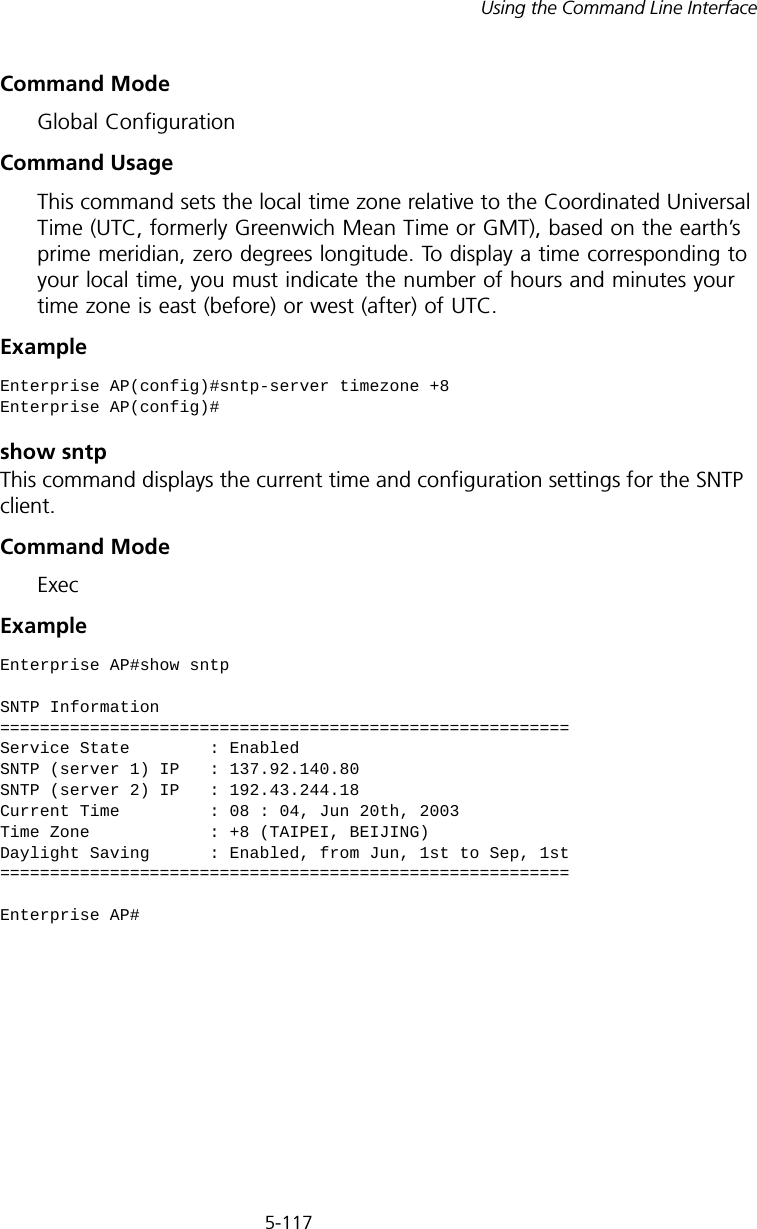
![5-116CHAPTER 5: COMMAND LINE INTERFACERelated Commandssntp-server enable (5-114)sntp-server daylight-savingThis command sets the start and end dates for daylight savings time. Use the no form to disable daylight savings time.Syntax[no] sntp-server daylight-saving Default Setting DisabledCommand Mode Global ConfigurationCommand Usage The command sets the system clock back one hour during the specified period.Example This sets daylight savings time to be used from July 1st to September 1st.sntp-server timezoneThis command sets the time zone for the access point’s internal clock.Syntaxsntp-server timezone <hours>hours - Number of hours before/after UTC. (Range: -12 to +12 hours)Default Setting -5 (BOGOTA, EASTERN, INDIANA)Enterprise AP(config)#sntp-server daylight-savingEnter Daylight saving from which month<1-12>: 6and which day<1-31>: 1Enter Daylight saving end to which month<1-12>: 9and which day<1-31>: 1Enterprise AP(config)#](https://usermanual.wiki/Hewlett-Packard-Enterprise/WL546.Users-Manual2/User-Guide-670090-Page-44.png)
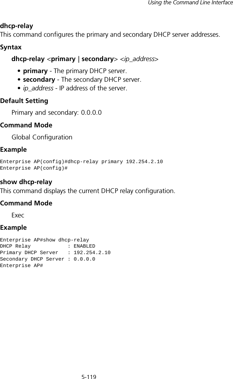
![5-118CHAPTER 5: COMMAND LINE INTERFACEDHCP Relay CommandsDynamic Host Configuration Protocol (DHCP) can dynamically allocate an IP address and other configuration information to network clients that broadcast a request. To receive the broadcast request, the DHCP server would normally have to be on the same subnet as the client. However, when the access point’s DHCP relay agent is enabled, received client requests can be forwarded directly by the access point to a known DHCP server on another subnet. Responses from the DHCP server are returned to the access point, which then broadcasts them back to clients.Tabl e 15 DHCP Relay Commandsdhcp-relay enableThis command enables the access point’s DHCP relay agent. Use the no form to disable the agent.Syntax[no] dhcp-relay enableDefault Setting DisabledCommand Mode Global ConfigurationCommand Usage • For the DHCP relay agent to function, the primary DHCP server must be configured using the dhcp-relay primary command. A secondary DHCP server does not need to be configured, but it is recommended.• If there is no response from the primary DHCP server, and a secondary server has been configured, the agent will then attempt to send DHCP requests to the secondary server.Example Command Function Mode Pagedhcp-relay enable Enables the DHCP relay agent GC 5-118dhcp-relay Sets the primary and secondary DHCP server addressGC 5-119show dhcp-relay Shows current DHCP relay configuration settingsExec 5-119Enterprise AP(config)#dhcp-relay enableEnterprise AP(config)#](https://usermanual.wiki/Hewlett-Packard-Enterprise/WL546.Users-Manual2/User-Guide-670090-Page-46.png)
![5-121Using the Command Line Interfacesnmp-server communityThis command defines the community access string for the Simple Network Management Protocol. Use the no form to remove the specified community string.Syntaxsnmp-server community string [ro | rw] no snmp-server community string•string - Community string that acts like a password and permits access to the SNMP protocol. (Maximum length: 23 characters, case sensitive)•ro - Specifies read-only access. Authorized management stations are only able to retrieve MIB objects. •rw - Specifies read/write access. Authorized management stations are able to both retrieve and modify MIB objects.Default Setting • public - Read-only access. Authorized management stations are only able to retrieve MIB objects.• private - Read/write access. Authorized management stations are able to both retrieve and modify MIB objects.Command Mode Global ConfigurationCommand Usage If you enter a community string without the ro or rw option, the default is read only.Example snmp-server contactThis command sets the system contact string. Use the no form to remove the system contact information.Syntaxsnmp-server contact string no snmp-server contactstring - String that describes the system contact. (Maximum length: 255 characters)Enterprise AP(config)#snmp-server community alpha rwEnterprise AP(config)#](https://usermanual.wiki/Hewlett-Packard-Enterprise/WL546.Users-Manual2/User-Guide-670090-Page-49.png)
![5-128CHAPTER 5: COMMAND LINE INTERFACE-group-name - The name of the SNMP group to which the user is assigned (32 characters maximum). There are three pre-defined groups: RO, RWAuth, or RWPriv.-auth-proto - The authentication type used for user authentication: md5 or none.-auth-passphrase - The user password required when authentication is used (8 – 32 characters).-priv-proto - The encryption type used for SNMP data encryption: des or none.-priv-passphrase - The user password required when data encryption is used (8 – 32 characters).• Users must be assigned to groups that have the same security levels. If a user who has “AuthPriv” security (uses authentication and encryption) is assigned to a read-only (RO) group, the user will not be able to access the database. An AuthPriv user must be assigned to the RWPriv group with the AuthPriv security level.• To configure a user for the RWAuth group, you must include the auth-proto and auth-passphrase keywords.• To configure a user for the RWPriv group, you must include the auth-proto, auth-passphrase, priv-proto, and priv-passphrase keywords.Example snmp-server targetsThis command configures SNMP v3 notification targets. Use the no form to delete an SNMP v3 target.Syntaxsnmp-server targets <target-id> <ip-addr> <sec-name> [version {3}] [udp-port {port-number}] [notification-type {TRAP}] no snmp-server targets <target-id>•target-id - A user-defined name that identifies a receiver of SNMP notifications. (Maximum length: 32 characters)Enterprise AP(config)#snmp-server user User Name<1-32> :chrisGroup Name<1-32> :RWPrivAuthtype(md5,<cr>none):md5Passphrase<8-32>:a good secretPrivacy(des,<cr>none) :desPassphrase<8-32>:a very good secretEnterprise AP(config)#](https://usermanual.wiki/Hewlett-Packard-Enterprise/WL546.Users-Manual2/User-Guide-670090-Page-56.png)
![5-129Using the Command Line Interface•ip-addr - Specifies the IP address of the management station to receive notifications.•sec-name - The defined SNMP v3 user name that is to receive notifications.•version - The SNMP version of notifications. Currently only version 3 is supported in this command.•udp-port - The UDP port that is used on the receiving management station for notifications.•notification-type - The type of notification that is sent. Currently only TRAP is supported.Default Setting NoneCommand Mode Global ConfigurationCommand Usage • The access point supports up to 10 SNMP v3 target IDs.• The SNMP v3 user name that is specified in the target must first be configured using the snmp-server user command.Example snmp-server filterThis command configures SNMP v3 notification filters. Use the no form to delete an SNMP v3 filter or remove a subtree from a filter.Syntaxsnmp-server filter <filter-id> <include | exclude> <subtree> [mask {mask}] no snmp-server filter <filter-id> [subtree]•filter-id - A user-defined name that identifies an SNMP v3 notification filter. (Maximum length: 32 characters)•include - Defines a filter type that includes objects in the MIB subtree.•exclude - Defines a filter type that excludes objects in the MIB subtree.•subtree - The part of the MIB subtree that is to be filtered.•mask - An optional hexadecimal value bit mask to define objects in the MIB subtree. Enterprise AP(config)#snmp-server targets mytraps 192.254.2.33 chrisEnterprise AP(config)#](https://usermanual.wiki/Hewlett-Packard-Enterprise/WL546.Users-Manual2/User-Guide-670090-Page-57.png)
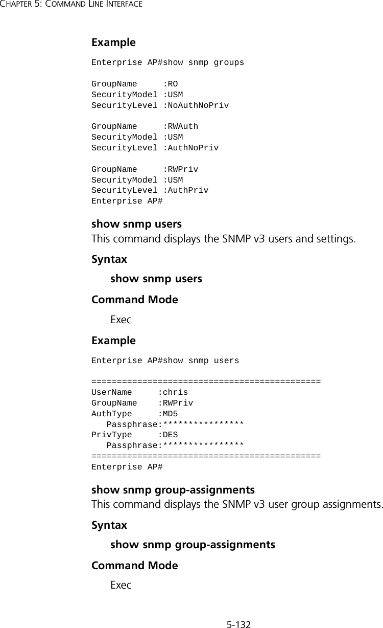
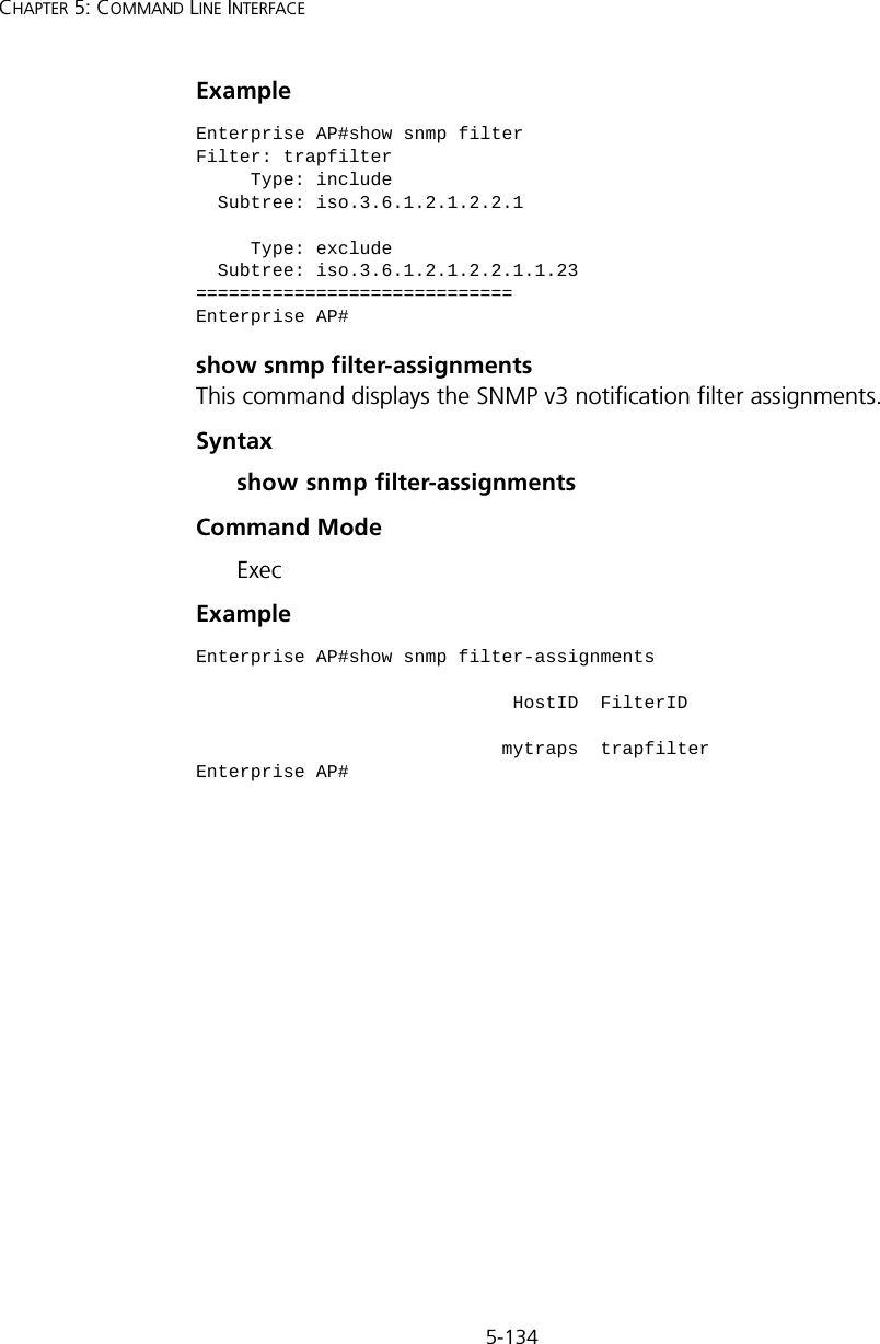
![5-133Using the Command Line InterfaceExample show snmp targetThis command displays the SNMP v3 notification target settings.Syntaxshow snmp targetCommand Mode ExecExample show snmp filterThis command displays the SNMP v3 notification filter settings.Syntaxshow snmp filter [filter-id] •filter-id - A user-defined name that identifies an SNMP v3 notification filter. (Maximum length: 32 characters)Command Mode ExecEnterprise AP#show snmp group-assignmentsGroupName :RWPrivUserName :chrisEnterprise AP#Enterprise AP#Enterprise AP#show snmp targetHost ID : mytrapsUser : chrisIP Address : 192.254.2.33UDP Port : 162=============================Enterprise AP#](https://usermanual.wiki/Hewlett-Packard-Enterprise/WL546.Users-Manual2/User-Guide-670090-Page-61.png)

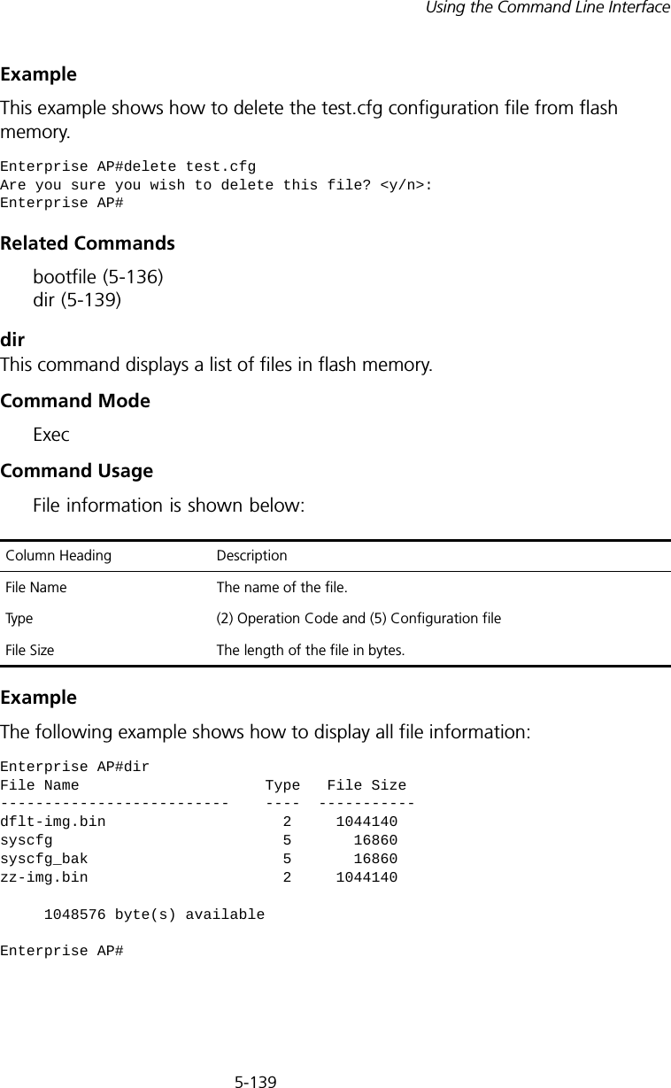
![5-138CHAPTER 5: COMMAND LINE INTERFACEExample The following example shows how to upload the configuration settings to a file on the TFTP server:The following example shows how to download a configuration file: deleteThis command deletes a file or image.Syntaxdelete <filename>filename - Name of the configuration file or image name.Default Setting NoneCommand Mode ExecEnterprise AP#copy config tftpTFTP Source file name:syscfgTFTP Server IP:192.254.2.19Enterprise AP#Enterprise AP#copy tftp file1. Application image2. Config file3. Boot block imageSelect the type of download<1,2,3>: [1]:2TFTP Source file name:syscfgTFTP Server IP:192.254.2.19Enterprise AP#NOTE: Beware of deleting application images from flash memory. At least one application image is required in order to boot the access point. If there are multiple image files in flash memory, and the one used to boot the access point is deleted, be sure you first use the bootfile command to update the application image file booted at startup before you reboot the access point.](https://usermanual.wiki/Hewlett-Packard-Enterprise/WL546.Users-Manual2/User-Guide-670090-Page-66.png)
![5-141Using the Command Line Interfaceradius-server addressThis command specifies the primary and secondary RADIUS servers. Syntaxradius-server [secondary] address <host_ip_address | host_name>•secondary - Secondary server.•host_ip_address - IP address of server.•host_name - Host name of server. (Range: 1-20 characters)Default Setting NoneCommand Mode Global ConfigurationExample radius-server portThis command sets the RADIUS server network port. Syntaxradius-server [secondary] port <port_number>•secondary - Secondary server.•port_number - RADIUS server UDP port used for authentication messages. (Range: 1024-65535)Default Setting 1812Command Mode Global Configurationradius-server vlan-format Sets the format for specifying VLAN IDs on the RADIUS serverGC 5-145show radius Shows the current RADIUS settings Exec 5-145Enterprise AP(config)#radius-server address 192.254.2.25Enterprise AP(config)#Command Function Mode Page](https://usermanual.wiki/Hewlett-Packard-Enterprise/WL546.Users-Manual2/User-Guide-670090-Page-69.png)
![5-142CHAPTER 5: COMMAND LINE INTERFACEExample radius-server keyThis command sets the RADIUS encryption key. Syntax radius-server [secondary] key <key_string>•secondary - Secondary server.•key_string - Encryption key used to authenticate logon access for client. Do not use blank spaces in the string. (Maximum length: 20 characters)Default Setting DEFAULTCommand Mode Global ConfigurationExample radius-server retransmitThis command sets the number of retries. Syntaxradius-server [secondary] retransmit number_of_retries•secondary - Secondary server.•number_of_retries - Number of times the access point will try to authenticate logon access via the RADIUS server. (Range: 1 - 30)Default Setting 3Command Mode Global ConfigurationExample Enterprise AP(config)#radius-server port 181Enterprise AP(config)#Enterprise AP(config)#radius-server key greenEnterprise AP(config)#Enterprise AP(config)#radius-server retransmit 5Enterprise AP(config)#](https://usermanual.wiki/Hewlett-Packard-Enterprise/WL546.Users-Manual2/User-Guide-670090-Page-70.png)
![5-143Using the Command Line Interfaceradius-server timeoutThis command sets the interval between transmitting authentication requests to the RADIUS server. Syntax radius-server [secondary] timeout number_of_seconds•secondary - Secondary server.•number_of_seconds - Number of seconds the access point waits for a reply before resending a request. (Range: 1-60)Default Setting 5Command Mode Global ConfigurationExample radius-server port-accountingThis command sets the RADIUS Accounting server network port. Syntaxradius-server [secondary] port-accounting <port_number>•secondary - Secondary server. If secondary is not specified, then the access point assumes you are configuring the primary RADIUS server.•port_number - RADIUS Accounting server UDP port used for accounting messages. (Range: 0 or 1024-65535)Default Setting 0 (disabled)Command Mode Global ConfigurationCommand Usage • When the RADIUS Accounting server UDP port is specified, a RADIUS accounting session is automatically started for each user that is successfully authenticated to the access point.Enterprise AP(config)#radius-server timeout 10Enterprise AP(config)#](https://usermanual.wiki/Hewlett-Packard-Enterprise/WL546.Users-Manual2/User-Guide-670090-Page-71.png)
![5-144CHAPTER 5: COMMAND LINE INTERFACEExample radius-server timeout-interimThis command sets the interval between transmitting accounting updates to the RADIUS server.Syntax radius-server [secondary] timeout-interim <number_of_seconds>•secondary - Secondary server.•number_of_seconds - Number of seconds the access point waits between transmitting accounting updates. (Range: 60-86400)Default Setting 3600Command Mode Global ConfigurationCommand Usage • The access point sends periodic accounting updates after every interim period until the user logs off and a “stop” message is sent.Example radius-server radius-mac-formatThis command sets the format for specifying MAC addresses on the RADIUS server.Syntaxradius-server radius-mac-format <multi-colon | multi-dash | no-delimiter | single-dash>•multi-colon - Enter MAC addresses in the form xx:xx:xx:xx:xx:xx.•multi-dash - Enter MAC addresses in the form xx-xx-xx-xx-xx-xx.•no-delimiter - Enter MAC addresses in the form xxxxxxxxxxxx.•single-dash - Enter MAC addresses in the form xxxxxx-xxxxxx.Enterprise AP(config)#radius-server port-accounting 1813Enterprise AP(config)#Enterprise AP(config)#radius-server timeout-interim 500Enterprise AP(config)#](https://usermanual.wiki/Hewlett-Packard-Enterprise/WL546.Users-Manual2/User-Guide-670090-Page-72.png)
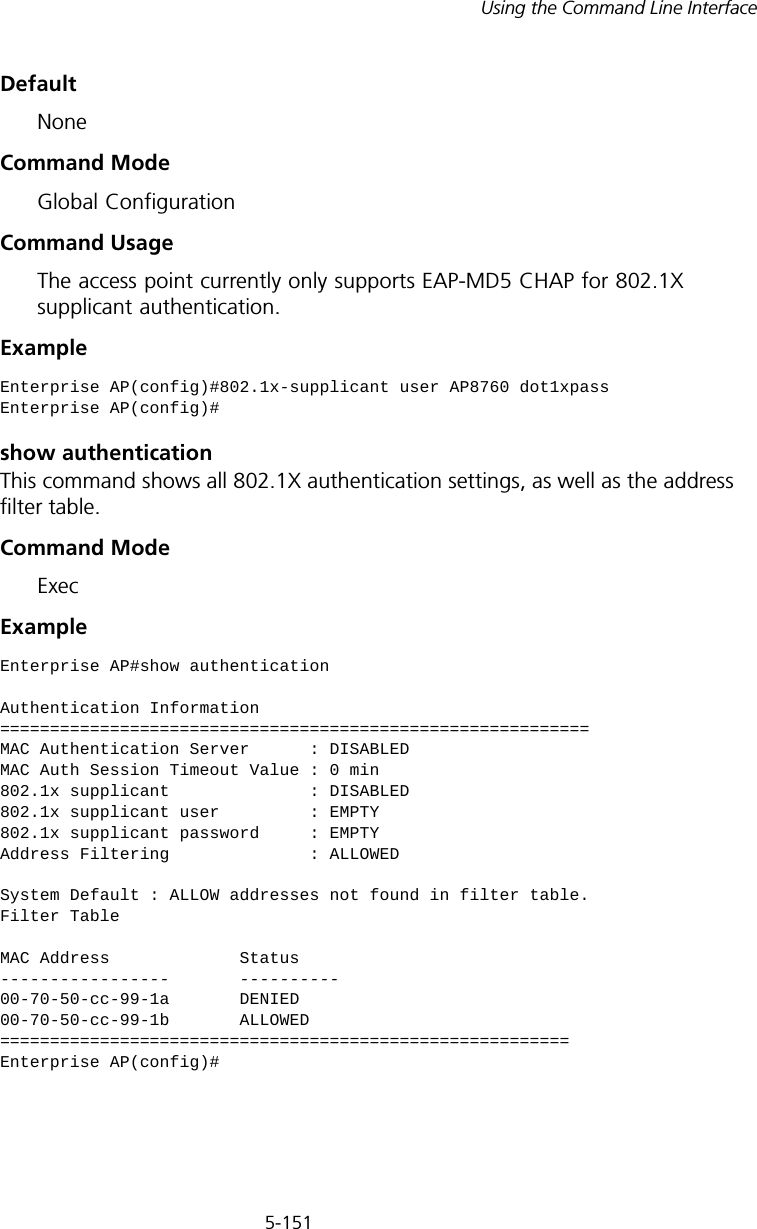
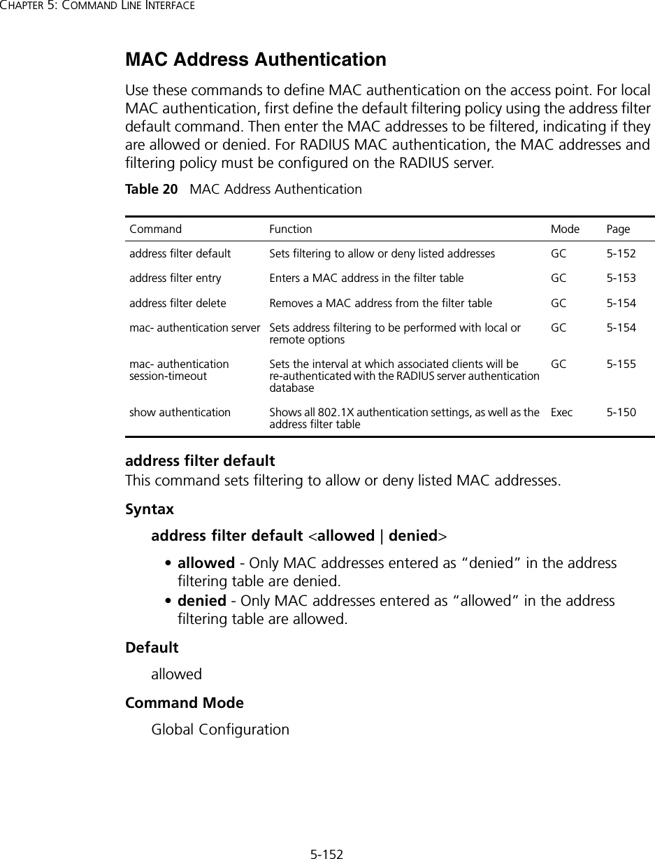
![5-154CHAPTER 5: COMMAND LINE INTERFACEaddress filter deleteThis command deletes a MAC address from the filter table.Syntaxaddress filter delete <mac-address>mac-address - Physical address of client. (Enter six pairs of hexadecimal digits separated by hyphens.)DefaultNoneCommand ModeGlobal ConfigurationExampleRelated Commands802.1x-supplicant user (5-150)mac-authentication serverThis command sets address filtering to be performed with local or remote options. Use the no form to disable MAC address authentication.Syntaxmac-authentication server [local | remote]•local - Authenticate the MAC address of wireless clients with the local authentication database during 802.11 association.•remote - Authenticate the MAC address of wireless clients with the RADIUS server during 802.1X authentication.DefaultDisabledCommand ModeGlobal ConfigurationExampleEnterprise AP(config)#address filter delete 00-70-50-cc-99-1b Enterprise AP(config)#Enterprise AP(config)#mac-authentication server remoteEnterprise AP(config)#](https://usermanual.wiki/Hewlett-Packard-Enterprise/WL546.Users-Manual2/User-Guide-670090-Page-82.png)
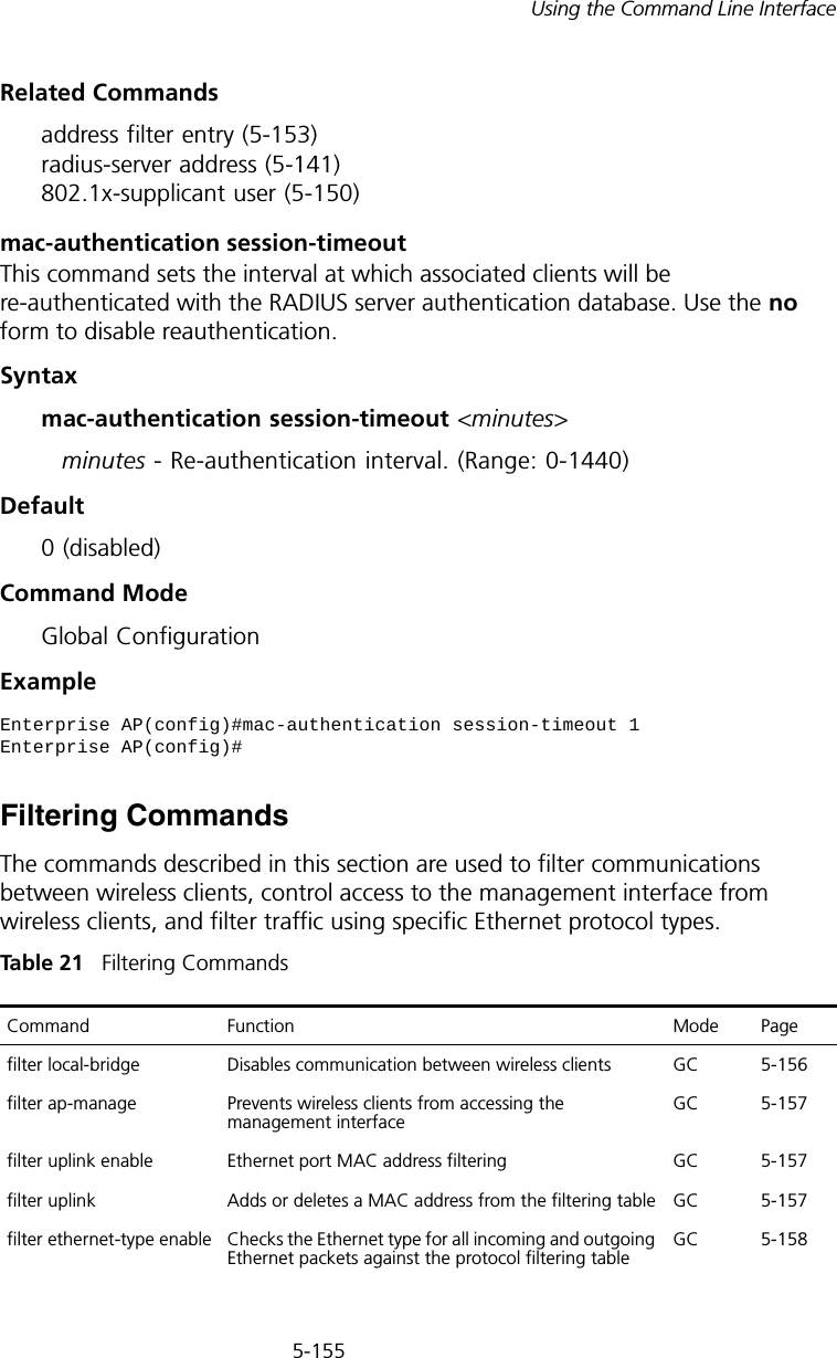
![5-157Using the Command Line Interfacefilter ap-manageThis command prevents wireless clients from accessing the management interface on the access point. Use the no form to disable this filtering.Syntax[no] filter ap-manageDefaultEnabledCommand ModeGlobal ConfigurationExamplefilter uplink enableThis command enables filtering of MAC addresses from the Ethernet port.Syntax[no] filter uplink enableDefaultDisabledCommand ModeGlobal ConfigurationExamplefilter uplinkThis command adds or deletes MAC addresses from the uplink filtering table.Syntaxfilter uplink <add | delete> MAC addressMAC address - Specifies a MAC address in the form xx-xx-xx-xx-xx-xx. A maximum of eight addresses can be added to the filtering table.Enterprise AP(config)#filter AP-manageEnterprise AP(config)#Enterprise AP(config)#filter uplink enableEnterprise AP(config)#](https://usermanual.wiki/Hewlett-Packard-Enterprise/WL546.Users-Manual2/User-Guide-670090-Page-85.png)
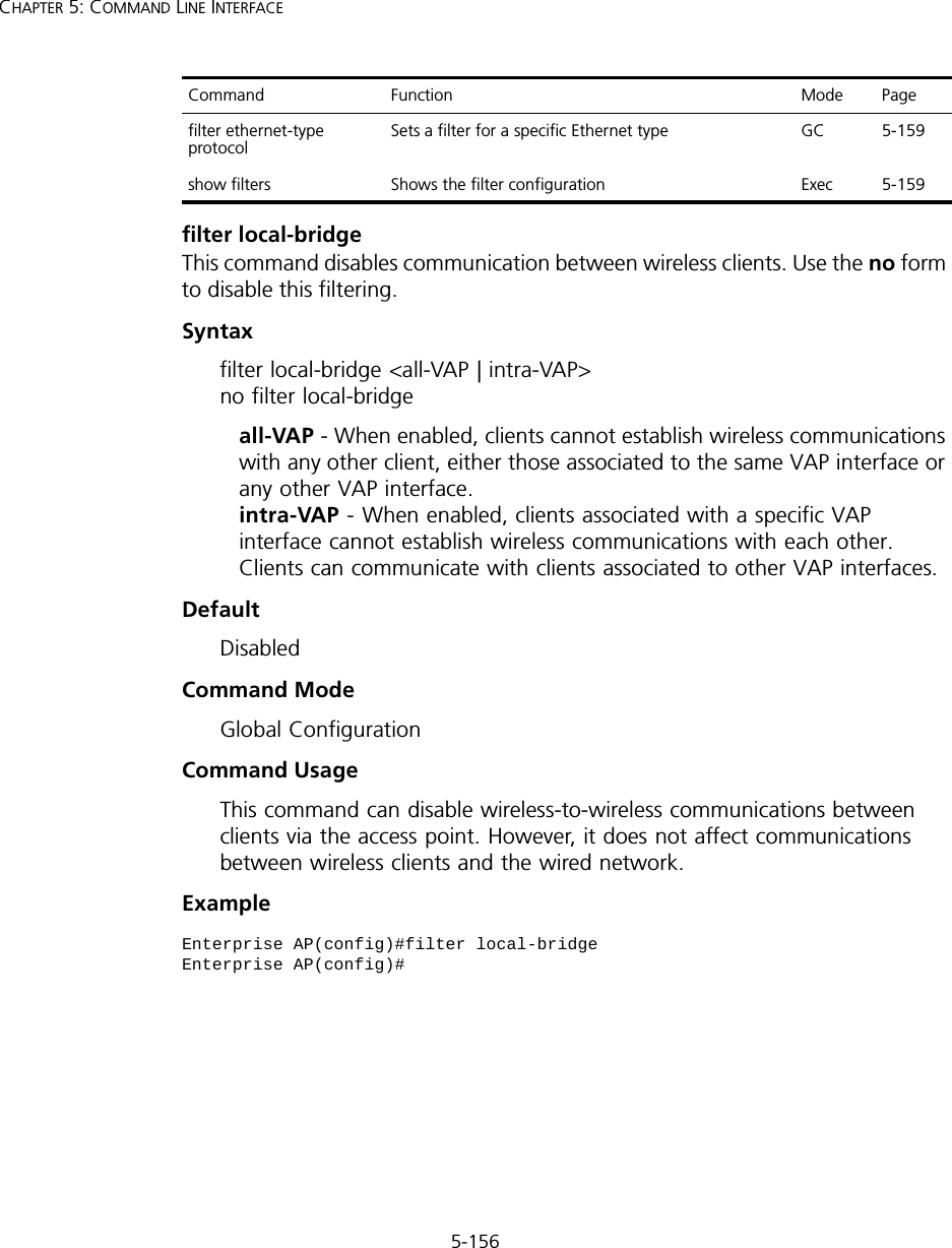
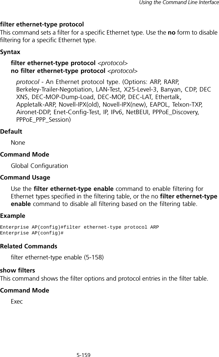
![5-158CHAPTER 5: COMMAND LINE INTERFACEDefaultDisabledCommand ModeGlobal ConfigurationExamplefilter ethernet-type enableThis command checks the Ethernet type on all incoming and outgoing Ethernet packets against the protocol filtering table. Use the no form to disable this feature.Syntax[no] filter ethernet-type enableDefaultDisabledCommand ModeGlobal ConfigurationCommand UsageThis command is used in conjunction with the filter ethernet-type protocol command to determine which Ethernet protocol types are to be filtered.ExampleRelated Commandsfilter ethernet-type protocol (5-159)Enterprise AP(config)#filter uplink add 00-12-34-56-78-9aEnterprise AP(config)#Enterprise AP(config)#filter ethernet-type enableEnterprise AP(config)#](https://usermanual.wiki/Hewlett-Packard-Enterprise/WL546.Users-Manual2/User-Guide-670090-Page-86.png)
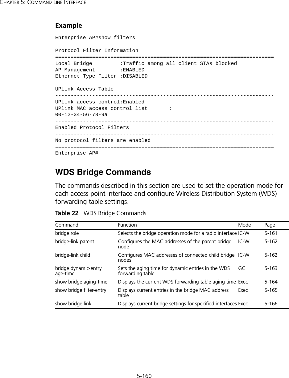
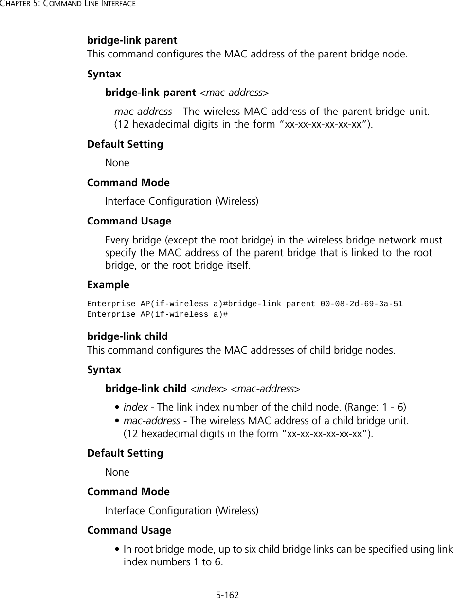

![5-166CHAPTER 5: COMMAND LINE INTERFACEshow bridge linkThis command displays WDS bridge link and spanning tree settings for specified interfaces.Syntaxshow bridge link <ethernet | wireless <a | g> [index]>•ethernet - Specifies the Ethernet interface.•wireless - Specifies a wireless interface.-a - The 802.11a radio interface.-g - The 802.11g radio interface.-index - The index number of a bridge link. (Range: 1 - 6)Command Mode ExecExample Enterprise AP#show bridge link wireless aInterface Wireless A WDS Information====================================AP Role: BridgeParent: 00-12-34-56-78-9aChild: Child 2: 00-08-12-34-56-de Child 3: 00-00-00-00-00-00 Child 4: 00-00-00-00-00-00 Child 5: 00-00-00-00-00-00 Child 6: 00-00-00-00-00-00STAs: No WDS Stations.Enterprise AP#](https://usermanual.wiki/Hewlett-Packard-Enterprise/WL546.Users-Manual2/User-Guide-670090-Page-94.png)
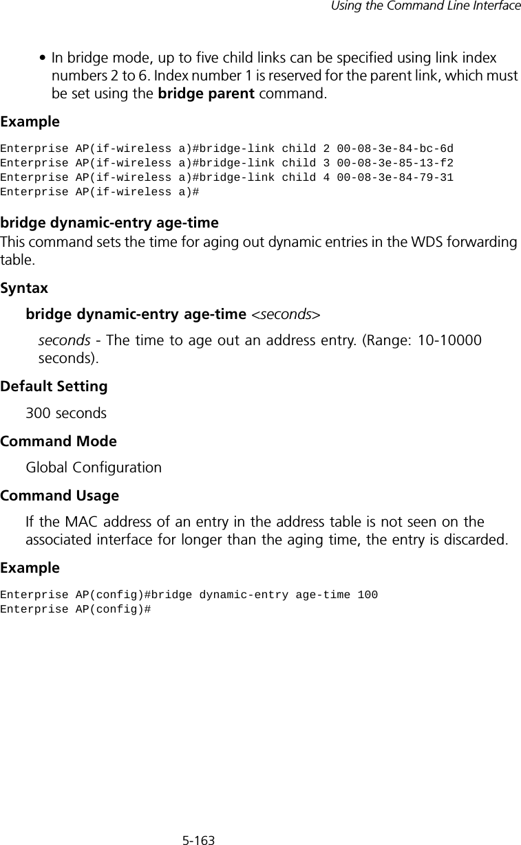
![5-168CHAPTER 5: COMMAND LINE INTERFACEbridge stp enableThis command enables the Spanning Tree Protocol. Use the no form to disable the Spanning Tree Protocol.Syntax [no] bridge stp enableDefault Setting EnabledCommand Mode Global ConfigurationExample This example globally enables the Spanning Tree Protocol.bridge stp forwarding-delayUse this command to configure the spanning tree bridge forward time globally for the wireless bridge. Use the no form to restore the default.Syntax bridge stp forwarding-delay <seconds>no bridge stp forwarding-delayseconds - Time in seconds. (Range: 4 - 30 seconds)The minimum value is the higher of 4 or [(max-age / 2) + 1]. show bridge stp Displays the global spanning tree settings Exec 5-172show bridge link Displays current bridge settings for specified interfaces Exec 5-166Enterprise AP(config)bridge stp enableEnterprise AP(config)Command Function Mode Page](https://usermanual.wiki/Hewlett-Packard-Enterprise/WL546.Users-Manual2/User-Guide-670090-Page-96.png)
![5-169Using the Command Line InterfaceDefault Setting 15 secondsCommand Mode Global ConfigurationCommand Usage This command sets the maximum time (in seconds) the root device will wait before changing states (i.e., discarding to learning to forwarding). This delay is required because every device must receive information about topology changes before it starts to forward frames. In addition, each port needs time to listen for conflicting information that would make it return to the discarding state; otherwise, temporary data loops might result.Example bridge stp hello-timeUse this command to configure the spanning tree bridge hello time globally for the wireless bridge. Use the no form to restore the default.Syntax bridge stp hello-time <time>no bridge stp hello-timetime - Time in seconds. (Range: 1-10 seconds). The maximum value is the lower of 10 or [(max-age / 2) -1]. Default Setting 2 secondsCommand Mode Global ConfigurationCommand Usage This command sets the time interval (in seconds) at which the root device transmits a configuration message.Example Enterprise AP(config)#bridge stp forwarding-delay 20Enterprise AP(config)#Enterprise AP(config)#bridge stp hello-time 5Enterprise AP(config)#](https://usermanual.wiki/Hewlett-Packard-Enterprise/WL546.Users-Manual2/User-Guide-670090-Page-97.png)
![5-170CHAPTER 5: COMMAND LINE INTERFACEbridge stp max-ageUse this command to configure the spanning tree bridge maximum age globally for the wireless bridge. Use the no form to restore the default.Syntax bridge stp max-age <seconds>no bridge stp max-ageseconds - Time in seconds. (Range: 6-40 seconds)The minimum value is the higher of 6 or [2 x (hello-time + 1)].The maximum value is the lower of 40 or [2 x (forward-time - 1)].Default Setting 20 secondsCommand Mode Global ConfigurationCommand Usage This command sets the maximum time (in seconds) a device can wait without receiving a configuration message before attempting to reconfigure. All device ports (except for designated ports) should receive configuration messages at regular intervals. Any port that ages out STP information (provided in the last configuration message) becomes the designated port for the attached LAN. If it is a root port, a new root port is selected from among the device ports attached to the network.Example bridge stp priorityUse this command to configure the spanning tree priority globally for the wireless bridge. Use the no form to restore the default.Syntax bridge stp priority<priority>no bridge stp prioritypriority - Priority of the bridge. (Range: 0 - 65535) Enterprise AP(config)#bridge stp max-age 40Enterprise AP(config)#](https://usermanual.wiki/Hewlett-Packard-Enterprise/WL546.Users-Manual2/User-Guide-670090-Page-98.png)
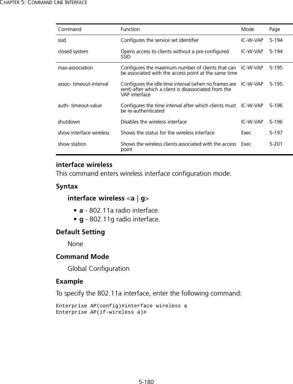
![5-176CHAPTER 5: COMMAND LINE INTERFACEip dhcp This command enables the access point to obtain an IP address from a DHCP server. Use the no form to restore the default IP address.Syntax [no] ip dhcpDefault Setting EnabledCommand Mode Interface Configuration (Ethernet)Command Usage • You must assign an IP address to this device to gain management access over the network or to connect the access point to existing IP subnets. You can manually configure a specific IP address using the ip address command, or direct the device to obtain an address from a DHCP server using this command. • When you use this command, the access point will begin broadcasting DHCP client requests. The current IP address (i.e., default or manually configured address) will continue to be effective until a DHCP reply is received. Requests will be broadcast periodically by this device in an effort to learn its IP address. (DHCP values can include the IP address, subnet mask, and default gateway.) ExampleRelated Commandsip address (5-175)Enterprise AP(config)#interface ethernetEnter Ethernet configuration commands, one per line.Enterprise AP(if-ethernet)#ip dhcpEnterprise AP(if-ethernet)#](https://usermanual.wiki/Hewlett-Packard-Enterprise/WL546.Users-Manual2/User-Guide-670090-Page-104.png)
![5-177Using the Command Line Interfacespeed-duplexThis command configures the speed and duplex mode of a given interface when autonegotiation is disabled. Use the no form to restore the default.Syntax speed-duplex <auto | 10MH | 10MF | 100MF | 100MH>•auto - autonegotiate speed and duplex mode•10MH - Forces 10 Mbps, half-duplex operation•10MF - Forces 10 Mbps, full-duplex operation •100MH - Forces 100 Mbps, half-duplex operation •100MF - Forces 100 Mbps, full-duplex operation Default Setting Auto-negotiation is enabled by default. Command Mode Interface Configuration (Ethernet)Command UsageIf autonegotiation is disabled, the speed and duplex mode must be configured to match the setting of the attached device.Example The following example configures the Ethernet port to 100 Mbps, full-duplex operation.shutdown This command disables the Ethernet interface. To restart a disabled interface, use the no form.Syntax [no] shutdownDefault Setting Interface enabledCommand Mode Interface Configuration (Ethernet)Enterprise AP(if-ethernet)#speed-duplex 100mfEnterprise AP(if-ethernet)#](https://usermanual.wiki/Hewlett-Packard-Enterprise/WL546.Users-Manual2/User-Guide-670090-Page-105.png)
![5-178CHAPTER 5: COMMAND LINE INTERFACECommand Usage This command allows you to disable the Ethernet port due to abnormal behavior (e.g., excessive collisions), and reenable it after the problem has been resolved. You may also want to disable the Ethernet port for security reasons. Example The following example disables the Ethernet port.show interface ethernetThis command displays the status for the Ethernet interface.Syntaxshow interface [ethernet]Default Setting Ethernet interfaceCommand Mode ExecExample Enterprise AP(if-ethernet)#shutdownEnterprise AP(if-ethernet)#Enterprise AP#show interface ethernetEthernet Interface Information========================================IP Address : 192.254.2.1Subnet Mask : 255.255.255.0Default Gateway : 192.254.2.253Primary DNS : 192.254.2.55Secondary DNS : 10.1.0.55Speed-duplex : 100Base-TX Half DuplexAdmin status : UpOperational status : Up========================================Enterprise AP#](https://usermanual.wiki/Hewlett-Packard-Enterprise/WL546.Users-Manual2/User-Guide-670090-Page-106.png)
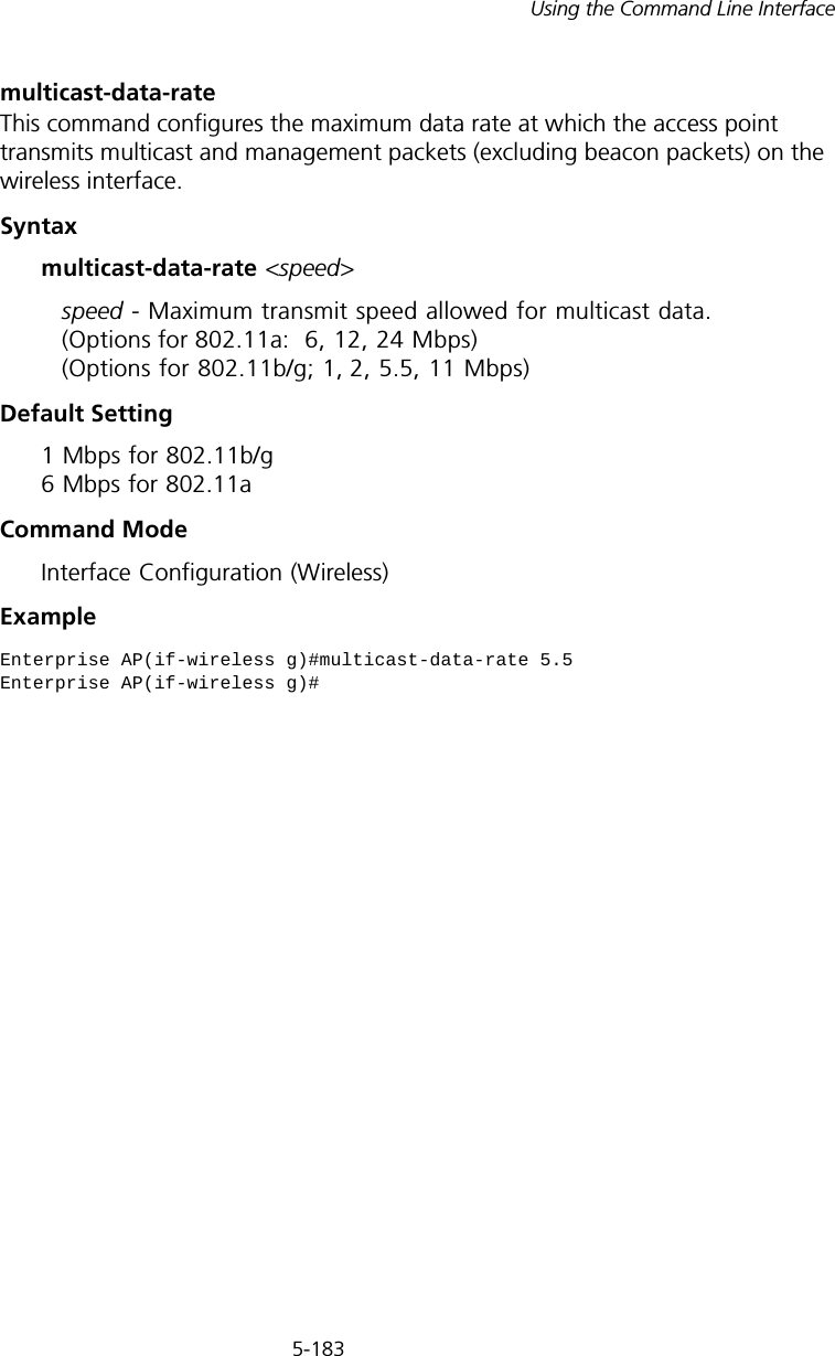
![5-181Using the Command Line InterfacevapThis command provides access to the VAP (Virtual Access Point) interface configuration mode.Syntaxvap <vap-id>vap-id - The number that identifies the VAP interface. (Options: 0-3)Default Setting NoneCommand Mode Interface Configuration (Wireless)ExamplespeedThis command configures the maximum data rate at which the access point transmits unicast packets. Syntaxspeed <speed>speed - Maximum access speed allowed for wireless clients. (Options for 802.11a: 6, 9, 12, 18, 24, 36, 48, 54 Mbps) (Options for 802.11b/g: 1, 2, 5.5, 6, 9, 11, 12, 18, 24, 36, 48, 54 Mbps)Default Setting 54 MbpsCommand Mode Interface Configuration (Wireless)Command Usage • The maximum transmission distance is affected by the data rate. The lower the data rate, the longer the transmission distance. Please refer to the table for maximum distances on page C-6.• When turbo mode is enabled (page 194) for 802.11a, the effective maximum speed specified by this command is double the entered value Enterprise AP(if-wireless g)#vap 0Enterprise AP(if-wireless g: VAP[0])#](https://usermanual.wiki/Hewlett-Packard-Enterprise/WL546.Users-Manual2/User-Guide-670090-Page-109.png)
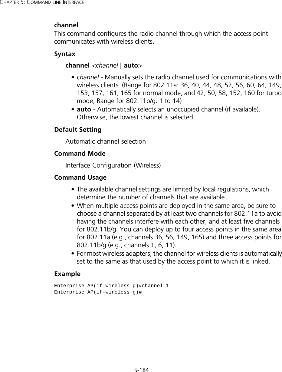
![5-186CHAPTER 5: COMMAND LINE INTERFACEDefault Settingb+g modeCommand ModeInterface Configuration (Wireless - 802.11g)Command Usage • For Japan, only 13 channels are available when set to g or b+g modes. When set to b mode, 14 channels are available.• Both the 802.11g and 802.11b standards operate within the 2.4 GHz band. If you are operating in g mode, any 802.11b devices in the service area will contribute to the radio frequency noise and affect network performance.ExamplepreambleThis command sets the length of the signal preamble that is used at the start of a 802.11b/g data transmission.Syntaxpreamble [long | short-or-long]•long - Sets the preamble to long (192 microseconds).•short-or-long - Sets the preamble to short if no 802.11b clients are detected (96 microseconds).Default SettingShort-or-LongCommand ModeInterface Configuration (Wireless - 802.11b/g)Command Usage• Using a short preamble instead of a long preamble can increase data throughput on the access point, but requires that all clients can support a short preamble.• Set the preamble to long to ensure the access point can support all 802.11b and 802.11g clients.Enterprise AP(if-wireless g)#radio-mode gEnterprise AP(if-wireless g)#](https://usermanual.wiki/Hewlett-Packard-Enterprise/WL546.Users-Manual2/User-Guide-670090-Page-114.png)
![5-192CHAPTER 5: COMMAND LINE INTERFACEDefault Setting 2347Command Mode Interface Configuration (Wireless)Command Usage • If the threshold is set to 0, the access point always sends RTS signals. If set to 2347, the access point never sends RTS signals. If set to any other value, and the packet size equals or exceeds the RTS threshold, the RTS/CTS (Request to Send / Clear to Send) mechanism will be enabled.• The access point sends RTS frames to a receiving station to negotiate the sending of a data frame. After receiving an RTS frame, the station sends a CTS frame to notify the sending station that it can start sending data. • Access points contending for the wireless medium may not be aware of each other. The RTS/CTS mechanism can solve this “Hidden Node” problem.Examplesuper-a This command enables Atheros proprietary Super A performance enhancements. Use the no form to disable this function.Syntax[no] super-a Default Setting DisabledCommand Mode Interface Configuration (Wireless - 802.11a)Command Usage Super A enhancements include bursting, compression, and fast frames. Maximum throughput ranges between 40 to 60 Mbps for connections to Atheros-compatible clients.Enterprise AP(if-wireless g)#rts-threshold 256Enterprise AP(if-wireless g)#](https://usermanual.wiki/Hewlett-Packard-Enterprise/WL546.Users-Manual2/User-Guide-670090-Page-120.png)
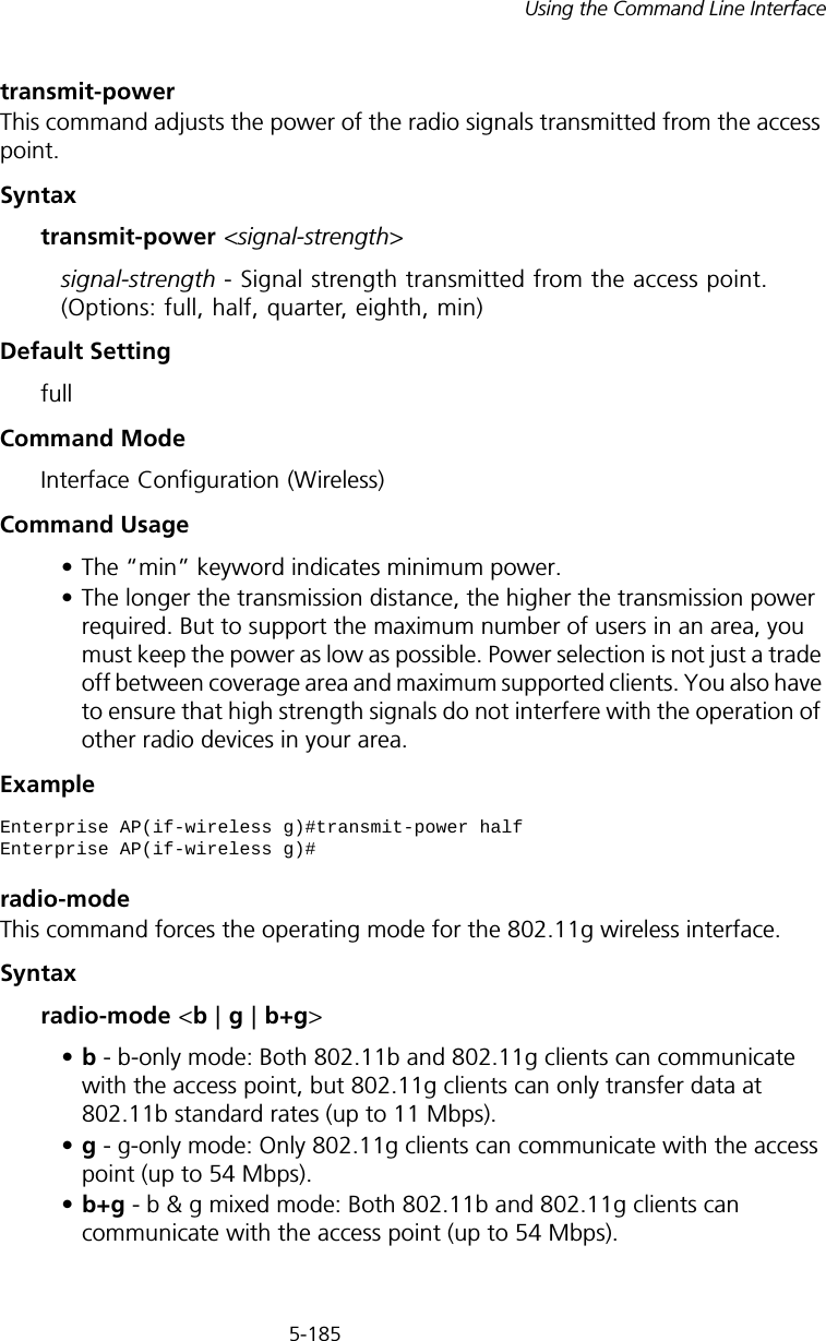
![5-193Using the Command Line InterfaceExamplesuper-g This command enables Atheros proprietary Super G performance enhancements. Use the no form to disable this function.Syntax[no] super-g Default Setting DisabledCommand Mode Interface Configuration (Wireless - 802.11g)Command Usage These enhancements include bursting, compression, fast frames and dynamic turbo. Maximum throughput ranges between 40 to 60 Mbps for connections to Atheros-compatible clients.Exampledescription This command adds a description to a the wireless interface. Use the no form to remove the description.Syntaxdescription <string> no descriptionstring - Comment or a description for this interface. (Range: 1-80 characters)Default Setting NoneCommand Mode Interface Configuration (Wireless-VAP)Enterprise AP(if-wireless a)#super aEnterprise AP(if-wireless a)#Enterprise AP(if-wireless a)#super gEnterprise AP(if-wireless a)#](https://usermanual.wiki/Hewlett-Packard-Enterprise/WL546.Users-Manual2/User-Guide-670090-Page-121.png)
![5-194CHAPTER 5: COMMAND LINE INTERFACEExamplessidThis command configures the service set identifier (SSID). Syntaxssid <string>string - The name of a basic service set supported by the access point. (Range: 1 - 32 characters)Default Setting 802.11a Radio: VAP_TEST_11A (0 to 3) 802.11g Radio: VAP_TEST_11G (0 to 3)Command Mode Interface Configuration (Wireless-VAP)Command Usage Clients that want to connect to the wireless network via an access point must set their SSIDs to the same as that of the access point.Exampleclosed-systemThis command prohibits access to clients without a pre-configured SSID. Use the no form to disable this feature.Syntax[no] closed-systemDefault Setting DisabledEnterprise AP(if-wireless g: VAP[0])#description RD-AP#3Enterprise AP(if-wireless g: VAP[0])#Enterprise AP(if-wireless g: VAP[0])#ssid RD-AP#3Enterprise AP(if-wireless g)#](https://usermanual.wiki/Hewlett-Packard-Enterprise/WL546.Users-Manual2/User-Guide-670090-Page-122.png)
![5-195Using the Command Line InterfaceCommand Mode Interface Configuration (Wireless-VAP)Command Usage When closed system is enabled, the access point will not include its SSID in beacon messages. Nor will it respond to probe requests from clients that do not include a fixed SSID.Examplemax-association This command configures the maximum number of clients that can be associated with the access point at the same time.Syntaxmax-association <count>count - Maximum number of associated stations. (Range: 0-64)Default Setting 64Command Mode Interface Configuration (Wireless-VAP)Example assoc-timeout-intervalThis command configures the idle time interval (when no frames are sent) after which the client is disassociated from the VAP interface.Syntaxassoc-timeout-interval <minutes>minutes - The number of minutes of inactivity before disassociation. (Range: 5-60)Enterprise AP(if-wireless g: VAP[0])#closed-systemEnterprise AP(if-wireless g)#Enterprise AP(if-wireless g: VAP[0])#max-association 32Enterprise AP(if-wireless g)#](https://usermanual.wiki/Hewlett-Packard-Enterprise/WL546.Users-Manual2/User-Guide-670090-Page-123.png)
![5-196CHAPTER 5: COMMAND LINE INTERFACEDefault Setting 30Command Mode Interface Configuration (Wireless-VAP)Exampleauth-timeout-valueThis command configures the time interval within which clients must complete authentication to the VAP interface.Syntaxauth-timeout-value <minutes>minutes - The number of minutes before re-authentication. (Range: 5-60)Default Setting 60Command Mode Interface Configuration (Wireless-VAP)Exampleshutdown This command disables the wireless interface. Use the no form to restart the interface.Syntax [no] shutdownDefault Setting Interface enabledCommand Mode Interface Configuration (Wireless-VAP)Enterprise AP(if-wireless g: VAP[0])#association-timeout-interval 20Enterprise AP(if-wireless g: VAP[0])#Enterprise AP(if-wireless g: VAP[0])#auth-timeout-value 40Enterprise AP(if-wireless g: VAP[0])#](https://usermanual.wiki/Hewlett-Packard-Enterprise/WL546.Users-Manual2/User-Guide-670090-Page-124.png)
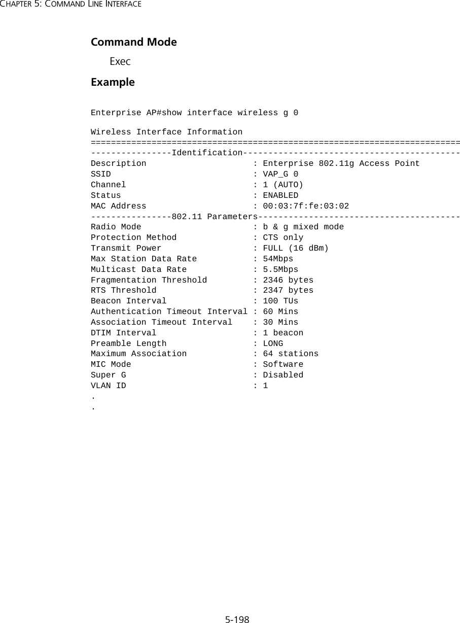
![5-197Using the Command Line InterfaceCommand UsageYou must first enable VAP interface 0 before you can enable VAP interfaces 1, 2, 3, 4, 5, 6, or 7.Example show interface wirelessThis command displays the status for the wireless interface.Syntaxshow interface wireless <a | g> vap-id•a - 802.11a radio interface.•g - 802.11g radio interface.•vap-id - The number that identifies the VAP interface. (Options: 0~3)Enterprise AP(if-wireless g: VAP[0])#shutdownEnterprise AP(if-wireless g)#](https://usermanual.wiki/Hewlett-Packard-Enterprise/WL546.Users-Manual2/User-Guide-670090-Page-125.png)
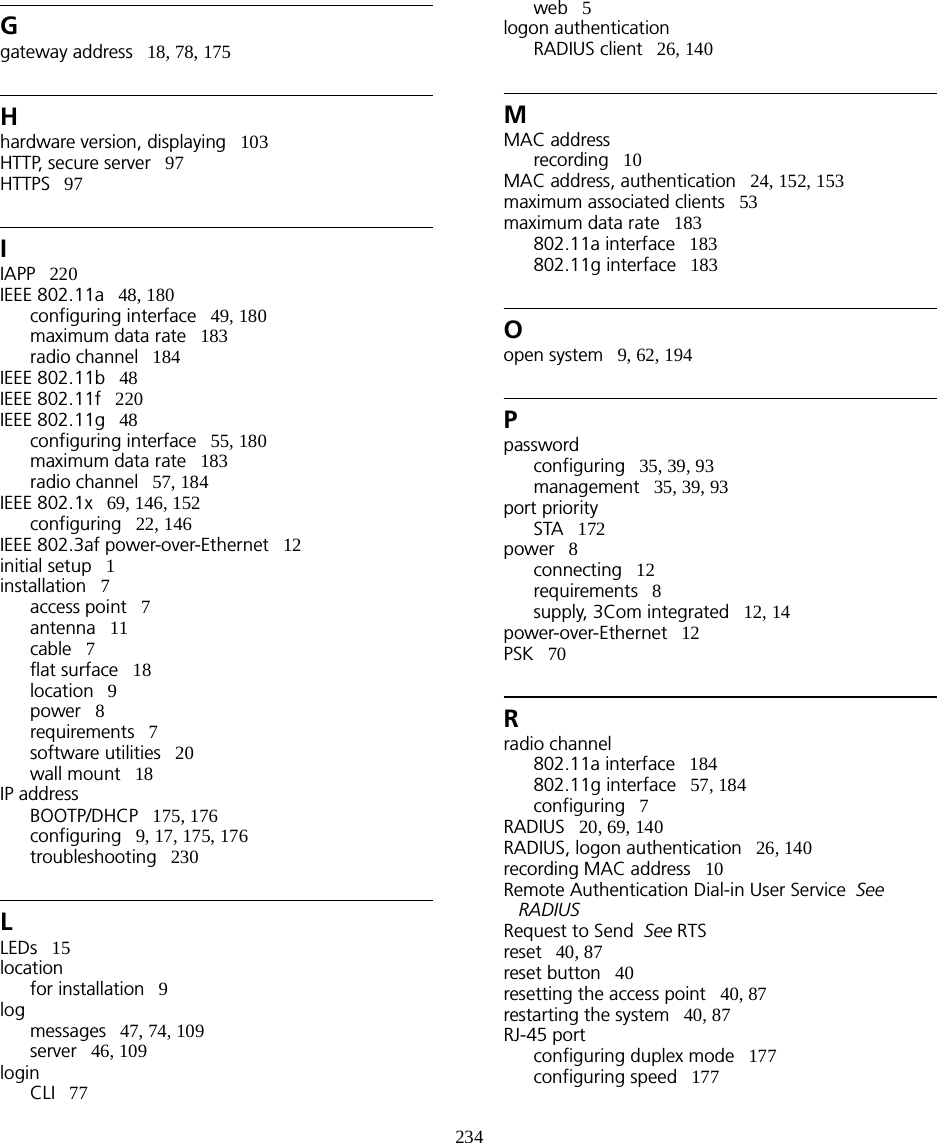
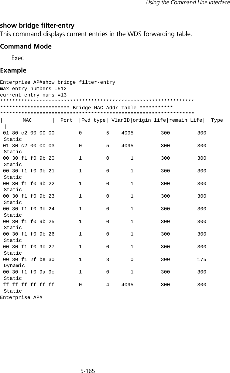
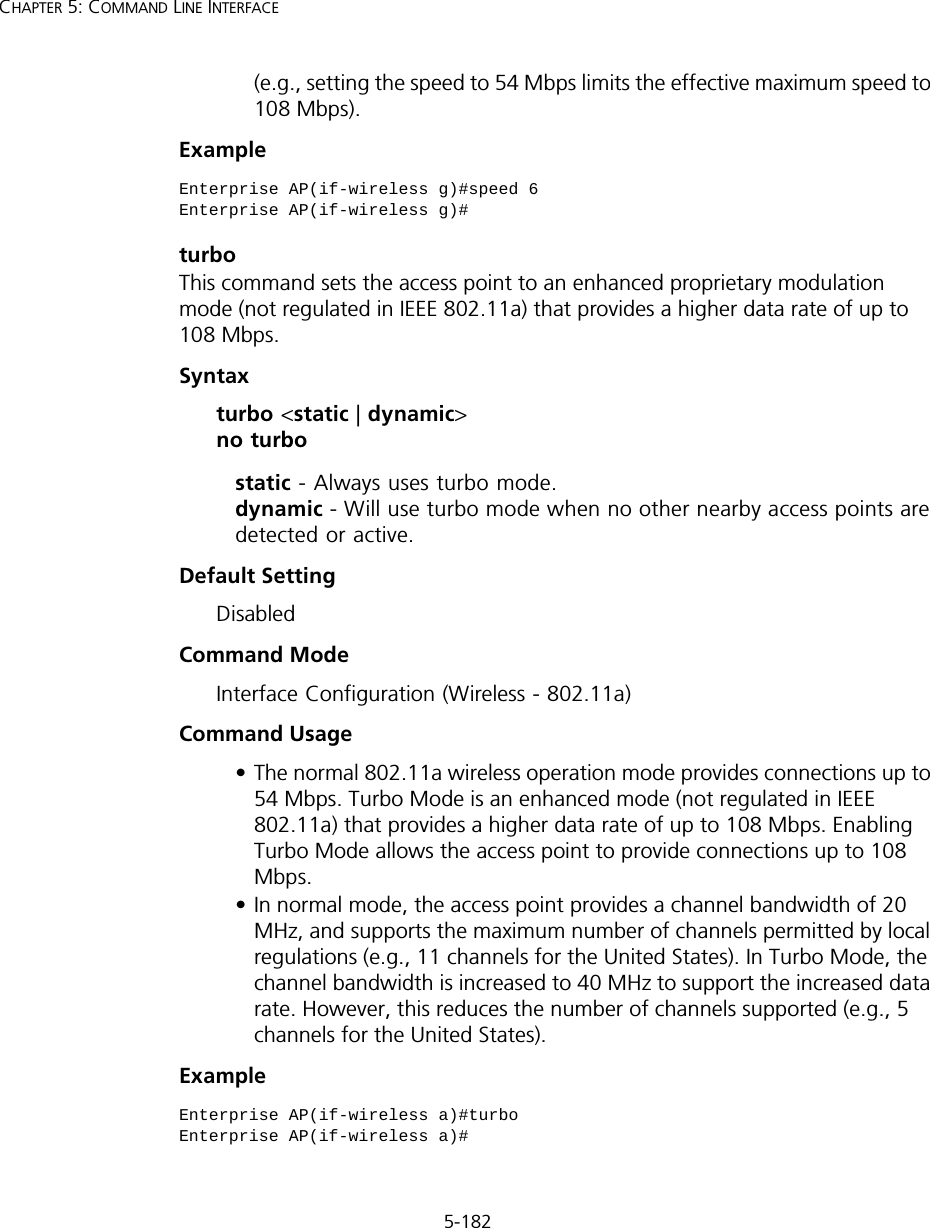
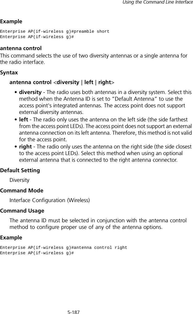
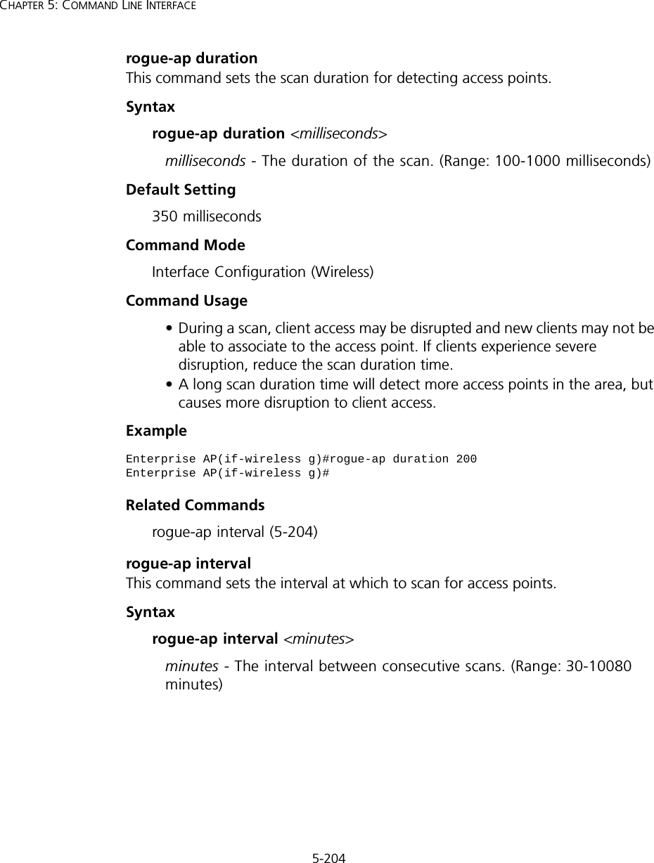
![5-201Using the Command Line Interfaceshow stationThis command shows the wireless clients associated with the access point.Command Mode ExecExample Rogue AP Detection CommandsA “rogue AP” is either an access point that is not authorized to participate in the wireless network, or an access point that does not have the correct security configuration. Rogue APs can potentially allow unauthorized users access to the network. Alternatively, client stations may mistakenly associate to a rogue AP and be prevented from accessing network resources. Rogue APs may also cause radio interference and degrade the wireless LAN performance.Enterprise AP#show stationStation Table Information========================================================if-wireless A VAP [0] :802.11a Channel : 60No 802.11a Channel Stations....if-wireless G VAP [0] :802.11g Channel : 1802.11g Channel Station TableStation Address : 00-04-23-94-9A-9C VLAN ID: 0Authenticated Associated Forwarding KeyTypeTRUE FALSE FALSE NONECounters:pkts Tx / Rx bytes Tx / Rx 20/ 0 721/ 0Time:Associated LastAssoc LastDisAssoc LastAuth 0 0 0 0if-wireless G VAP [1] :802.11g Channel : 1No 802.11g Channel Stations....Enterprise AP#](https://usermanual.wiki/Hewlett-Packard-Enterprise/WL546.Users-Manual2/User-Guide-670090-Page-129.png)
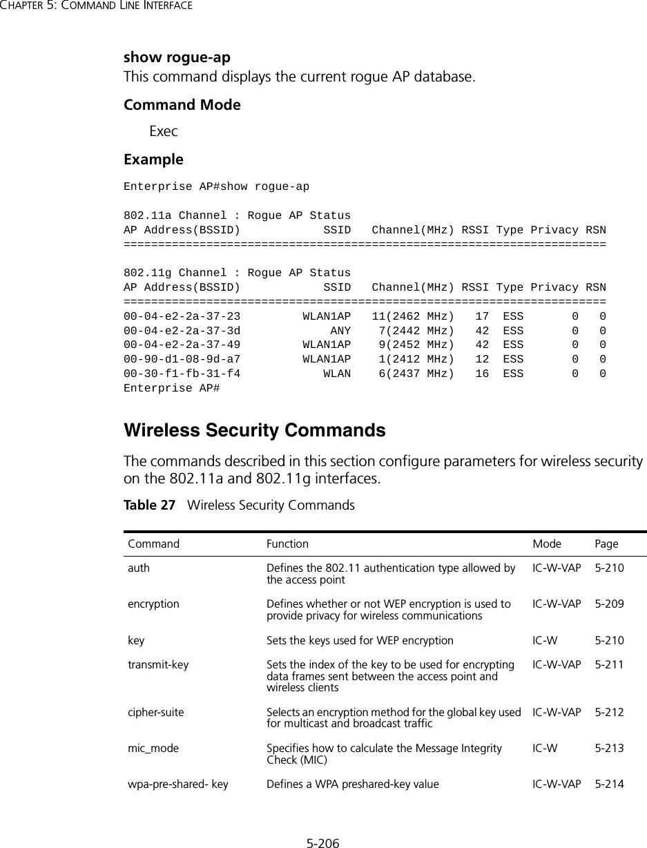
![5-202CHAPTER 5: COMMAND LINE INTERFACEThe access point can be configured to periodically scan all radio channels and find other access points within range. A database of nearby access points is maintained where any rogue APs can be identified.Tabl e 26 Rogue AP Commandsrogue-ap enableThis command enables the periodic detection of nearby access points. Use the no form to disable periodic detection.Syntax[no] rogue-ap enableDefault SettingDisabledCommand Mode Interface Configuration (Wireless)Command Usage • While the access point scans a channel for rogue APs, wireless clients will not be able to connect to the access point. Therefore, avoid frequent scanning or scans of a long duration unless there is a reason to believe that more intensive scanning is required to find a rogue AP.• A “rogue AP” is either an access point that is not authorized to participate in the wireless network, or an access point that does not have the correct security configuration. Rogue access points can be identified by unknown BSSID (MAC address) or SSID configuration. A database of nearby access points should therefore be maintained on a RADIUS server, allowing any rogue APs to be identified (see “rogue-ap authenticate” on page 203). Command Function Mode Pagerogue-ap enable Enables the periodic detection of other nearby access points GC 5-202rogue-ap authenticate Enables identification of all access points GC 5-203rogue-ap duration Sets the duration that all channels are scanned GC 5-204rogue-ap interval Sets the time between each scan GC 5-204rogue-ap scan Forces an immediate scan of all radio channels GC 5-205show rogue-ap Shows the current database of detected access points Exec 5-206](https://usermanual.wiki/Hewlett-Packard-Enterprise/WL546.Users-Manual2/User-Guide-670090-Page-130.png)
![5-203Using the Command Line InterfaceThe rogue AP database can be viewed using the show rogue-ap command.• The access point sends Syslog messages for each detected access point during a rogue AP scan.Example rogue-ap authenticateThis command forces the unit to authenticate all access points on the network. Use the no form to disable this function.Syntax[no] rogue-ap authenticateDefault SettingDisabledCommand Mode Interface Configuration (Wireless)Command Usage Enabling authentication in conjunction with a database of approved access points stored on a RADIUS server allows the access point to discover rogue APs. With authentication enabled and a configure RADIUS server, the access point checks the MAC address/Basic Service Set Identifier (BSSID) of each access point that it finds against a RADIUS server to determine whether the access point is allowed. With authentication disabled, the access point can identify its neighboring access points only; it cannot identify whether the access points are allowed or are rogues. If you enable authentication, you should also configure a RADIUS server for this access point (see “RADIUS” on page 20).Example Enterprise AP(if-wireless g)#rogue-ap enableconfigure either syslog or trap or both to receive the rogue APs detected.Enterprise AP(if-wireless g)#Enterprise AP(if-wireless g)#rogue-ap authenticateEnterprise AP(if-wireless g)#](https://usermanual.wiki/Hewlett-Packard-Enterprise/WL546.Users-Manual2/User-Guide-670090-Page-131.png)
![5-209Using the Command Line InterfaceWEP). To place the VAP into AES only mode, use “required” and then select the “cipher-ccmp” option for the cipher-suite command.ExampleRelated Commandsencryption (5-209) key (5-210)encryption This command enables data encryption for wireless communications. Use the no form to disable data encryption.Syntax[no] encryptionDefault Setting disabledCommand Mode Interface Configuration (Wireless-VAP)Command Usage • Wired Equivalent Privacy (WEP) is implemented in this device to prevent unauthorized access to your wireless network. For more secure data transmissions, enable encryption with this command, and set at least one static WEP key with the key command. • The WEP settings must be the same on each client in your wireless network.• Note that WEP protects data transmitted between wireless nodes, but does not protect any transmissions over your wired network or over the Internet.• You must enable data encryption in order to enable all types of encryption (WEP, TKIP, and AES-CCMP) in the access point. Enterprise AP(if-wireless g: VAP[0])#auth shared-keyEnterprise AP(if-wireless g)#](https://usermanual.wiki/Hewlett-Packard-Enterprise/WL546.Users-Manual2/User-Guide-670090-Page-137.png)
![5-210CHAPTER 5: COMMAND LINE INTERFACEExampleRelated Commandskey (5-210)key This command sets the keys used for WEP encryption. Use the no form to delete a configured key.Syntaxkey <index> <size> <type> <value> no key index•index - Key index. (Range: 1-4)•size - Key size. (Options: 64, 128, or 152 bits)•type - Input format. (Options: ASCII, HEX)•value - The key string.- For 64-bit keys, use 5 alphanumeric characters or 10 hexadecimal digits.- For 128-bit keys, use 13 alphanumeric characters or 26 hexadecimal digits.- For 152-bit keys, use 16 alphanumeric characters or 32 hexadecimal digits.Default Setting NoneCommand Mode Interface Configuration (Wireless)Command Usage • To enable Wired Equivalent Privacy (WEP), use the auth shared-key command to select the “shared key” authentication type, use the key command to configure at least one key, and use the transmit-key command to assign a key to one of the VAP interfaces.• If WEP option is enabled, all wireless clients must be configured with the same shared keys to communicate with the access point.• The encryption index, length and type configured in the access point must match those configured in the clients.Enterprise AP(if-wireless g: VAP[0])#encryptionEnterprise AP(if-wireless g)#](https://usermanual.wiki/Hewlett-Packard-Enterprise/WL546.Users-Manual2/User-Guide-670090-Page-138.png)
![5-211Using the Command Line InterfaceExampleRelated Commandskey (5-210) encryption (5-209) transmit-key (5-211)transmit-keyThis command sets the index of the key to be used for encrypting data frames for broadcast or multicast traffic transmitted from the VAP to wireless clients.Syntaxtransmit-key <index>index - Key index. (Range: 1-4)Default Setting 1Command Mode Interface Configuration (Wireless-VAP)Command Usage • If you use WEP key encryption option, the access point uses the transmit key to encrypt multicast and broadcast data signals that it sends to client devices. Other keys can be used for decryption of data from clients.• When using IEEE 802.1X, the access point uses a dynamic key to encrypt unicast and broadcast messages to 802.1X-enabled clients. However, because the access point sends the keys during the 802.1X authentication process, these keys do not have to appear in the client’s key list.• In a mixed-mode environment with clients using static and dynamic keys, select transmit key index 2, 3, or 4. The access point uses transmit key index 1 for the generation of dynamic keys.Example Enterprise AP(if-wireless g)#key 1 64 hex 1234512345Enterprise AP(if-wireless g)#key 2 128 ascii asdeipadjsipdEnterprise AP(if-wireless g)#key 3 64 hex 12345123451234512345123456Enterprise AP(if-wireless g)#Enterprise AP(if-wireless g: VAP[0])#transmit-key 2Enterprise AP(if-wireless g)#](https://usermanual.wiki/Hewlett-Packard-Enterprise/WL546.Users-Manual2/User-Guide-670090-Page-139.png)
![5-213Using the Command Line Interface• AES-CCMP (Advanced Encryption Standard Counter-Mode/CBCMAC Protocol): WPA2 is backward compatible with WPA, including the same 802.1X and PSK modes of operation and support for TKIP encryption. The main enhancement is its use of AES Counter-Mode encryption with Cipher Block Chaining Message Authentication Code (CBC-MAC) for message integrity. The AES Counter-Mode/CBCMAC Protocol (AES-CCMP) provides extremely robust data confidentiality using a 128-bit key. The AES-CCMP encryption cipher is specified as a standard requirement for WPA2. However, the computational intensive operations of AES-CCMP requires hardware support on client devices. Therefore to implement WPA2 in the network, wireless clients must be upgraded to WPA2-compliant hardware.Example mic_mode This command specifies how to calculate the Message Integrity Check (MIC). Syntaxmic_mode <hardware | software>•hardware - Uses hardware to calculate the MIC.•software - Uses software to calculate the MIC.Default Setting softwareCommand Mode Interface Configuration (Wireless)Command Usage • The Michael Integrity Check (MIC) is part of the Temporal Key Integrity Protocol (TKIP) encryption used in Wi-Fi Protected Access (WPA) security. The MIC calculation is performed in the access point for each transmitted packet and this can impact throughput and performance. The access point supports a choice of hardware or software for MIC calculation. The performance of the access point can be improved by selecting the best method for the specific deployment. • Using the “hardware” option provides best performance when the number of supported clients is less than 27. Enterprise AP(if-wireless g: VAP[0])#cipher-suite TKIPEnterprise AP(if-wireless g)#](https://usermanual.wiki/Hewlett-Packard-Enterprise/WL546.Users-Manual2/User-Guide-670090-Page-141.png)
![5-214CHAPTER 5: COMMAND LINE INTERFACE• Using the “software” option provides the best performance for a large number of clients on one radio interface. Throughput may be reduced when both 802.11a and 802.11g interfaces are supporting a high number of clients simultaneously.Example wpa-pre-shared-key This command defines a Wi-Fi Protected Access (WPA/WPA2) Pre-shared-key.Syntaxwpa-pre-shared-key <hex | passphrase-key> <value>•hex - Specifies hexadecimal digits as the key input format.•passphrase-key - Specifies an ASCII pass-phrase string as the key input format.•value - The key string. For ASCII input, specify a string between 8 and 63 characters. For HEX input, specify exactly 64 digits.Command Mode Interface Configuration (Wireless-VAP)Command Usage • To support WPA or WPA2 for client authentication, use the auth command to specify the authentication type, and use the wpa-preshared-key command to specify one static key.• If WPA or WPA2 is used with pre-shared-key mode, all wireless clients must be configured with the same pre-shared key to communicate with the access point’s VAP interface.Example Related Commandsauth (5-207)Enterprise AP(if-wireless a)#mic_mode hardwareEnterprise AP(if-wireless g)#Enterprise AP(if-wireless g: VAP[0])#wpa-pre-shared-key ASCII agoodsecretEnterprise AP(if-wireless g)#](https://usermanual.wiki/Hewlett-Packard-Enterprise/WL546.Users-Manual2/User-Guide-670090-Page-142.png)
![5-215Using the Command Line Interfacepmksa-lifetime This command sets the time for aging out cached WPA2 Pairwise Master Key Security Association (PMKSA) information for fast roaming.Syntaxpmksa-lifetime <minutes>minutes - The time for aging out PMKSA information. (Range: 0 - 14400 minutes)Default Setting 720 minutesCommand Mode Interface Configuration (Wireless-VAP)Command Usage • WPA2 provides fast roaming for authenticated clients by retaining keys and other security information in a cache, so that if a client roams away from an access point and then returns reauthentication is not required. • When a WPA2 client is first authenticated, it receives a Pairwise Master Key (PMK) that is used to generate other keys for unicast data encryption. This key and other client information form a Security Association that the access point names and holds in a cache. The lifetime of this security association can be configured with this command. When the lifetime expires, the client security association and keys are deleted from the cache. If the client returns to the access point, it requires full reauthentication.• The access point can store up to 256 entries in the PMKSA cache. Example pre-authentication This command enables WPA2 pre-authentication for fast secure roaming.Syntaxpre-authentication <enable | disable>•enable - Enables pre-authentication for the VAP interface. •disable - Disables pre-authentication for the VAP interface.Enterprise AP(if-wireless g: VAP[0])#wpa-pre-shared-key ASCII agoodsecretEnterprise AP(if-wireless g: VAP[0])#](https://usermanual.wiki/Hewlett-Packard-Enterprise/WL546.Users-Manual2/User-Guide-670090-Page-143.png)
![5-216CHAPTER 5: COMMAND LINE INTERFACEDefault Setting DisabledCommand Mode Interface Configuration (Wireless-VAP)Command Usage • Each time a client roams to another access point it has to be fully re-authenticated. This authentication process is time consuming and can disrupt applications running over the network. WPA2 includes a mechanism, known as pre-authentication, that allows clients to roam to a new access point and be quickly associated. The first time a client is authenticated to a wireless network it has to be fully authenticated. When the client is about to roam to another access point in the network, the access point sends pre-authentication messages to the new access point that include the client’s security association information. Then when the client sends an association request to the new access point the client is known to be already authenticated, so it proceeds directly to key exchange and association.• To support pre-authentication, both clients and access points in the network must be WPA2 enabled.• Pre-authentication requires all access points in the network to be on the same IP subnet.Example Enterprise AP(if-wireless g: VAP[0])#wpa-pre-shared-key ASCII agoodsecretEnterprise AP(if-wireless g: VAP[0])#](https://usermanual.wiki/Hewlett-Packard-Enterprise/WL546.Users-Manual2/User-Guide-670090-Page-144.png)
![5-217Using the Command Line InterfaceLink Integrity CommandsThe access point provides a link integrity feature that can be used to ensure that wireless clients are connected to resources on the wired network. The access point does this by periodically sending Ping messages to a host device in the wired Ethernet network. If the access point detects that the connection to the host has failed, it disables the radio interfaces, forcing clients to find and associate with another access point. When the connection to the host is restored, the access point re-enables the radio interfaces.Tabl e 28 Link Integrity Commandslink-integrity ping-detectThis command enables link integrity detection. Use the no form to disable link integrity detection.Syntax[no] link-integrity ping-detectDefault SettingDisabledCommand Mode Global ConfigurationCommand Usage • When link integrity is enabled, the IP address of a host device in the wired network must be specified.• The access point periodically sends an ICMP echo request (Ping) packet to the link host IP address. When the number of failed responses (either the Command Function Mode Pagelink-integrity ping-detect Enables link integrity detection GC 5-217link-integrity ping-host Specifies the IP address of a host device in the wired networkGC 5-218link-integrity ping-interval Specifies the time between each Ping sent to the link host GC 5-218link-integrity ping-fail-retry Specifies the number of consecutive failed Ping counts before the link is determined as lostGC 5-219link-integrity ethernet-detect Enables integrity check for Ethernet link GC 5-219show link-integrity Displays the current link integrity configuration Exec 5-220](https://usermanual.wiki/Hewlett-Packard-Enterprise/WL546.Users-Manual2/User-Guide-670090-Page-145.png)
![5-219Using the Command Line InterfaceExample link-integrity ping-fail-retryThis command configures the number of consecutive failed Ping counts before the link is determined as lost.Syntaxlink-integrity ping-fail-retry <counts>counts - The number of failed Ping counts before the link is determined as lost. (Range: 1 - 10)Default Setting6Command Mode Global ConfigurationExample link-integrity ethernet-detectThis command enables an integrity check to determine whether or not the access point is connected to the wired Ethernet.Syntax[no] link-integrity ethernet-detectDefault SettingDisabledCommand Mode Global ConfigurationExample Enterprise AP(config)#link-integrity ping-interval 20Enterprise AP(config)#Enterprise AP(config)#link-integrity ping-fail-retry 10Enterprise AP(config)#Enterprise AP(config)#link-integrity ethernet-detectNotification : Ethernet Link Detect SUCCESS - RADIO(S) ENABLEDEnterprise AP(config)#](https://usermanual.wiki/Hewlett-Packard-Enterprise/WL546.Users-Manual2/User-Guide-670090-Page-147.png)
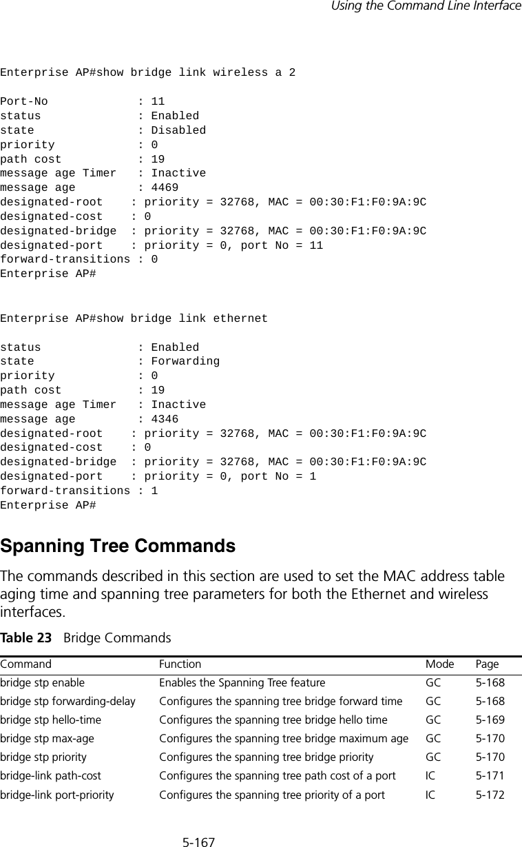
![5-220CHAPTER 5: COMMAND LINE INTERFACEshow link-integrityThis command displays the current link integrity configuration.Command Mode ExecExample IAPP CommandsThe command described in this section enables the protocol signaling required to ensure the successful handover of wireless clients roaming between different 802.11f-compliant access points. In other words, the 802.11f protocol can ensure successful roaming between access points in a multi-vendor environment.iappThis command enables the protocol signaling required to hand over wireless clients roaming between different 802.11f-compliant access points. Use the no form to disable 802.11f signaling.Syntax[no] iappDefaultEnabledCommand ModeGlobal ConfigurationCommand UsageThe current 802.11 standard does not specify the signaling required between access points in order to support clients roaming from one access point to another. In particular, this can create a problem for clients roaming Enterprise AP#show link-integrityLink Integrity Information=========================================================== Ethernet Detect : Enabled Ping Detect : Enabled Target IP/Name : 192.254.0.140 Ping Fail Retry : 6 Ping Interval : 30===========================================================Enterprise AP#](https://usermanual.wiki/Hewlett-Packard-Enterprise/WL546.Users-Manual2/User-Guide-670090-Page-148.png)
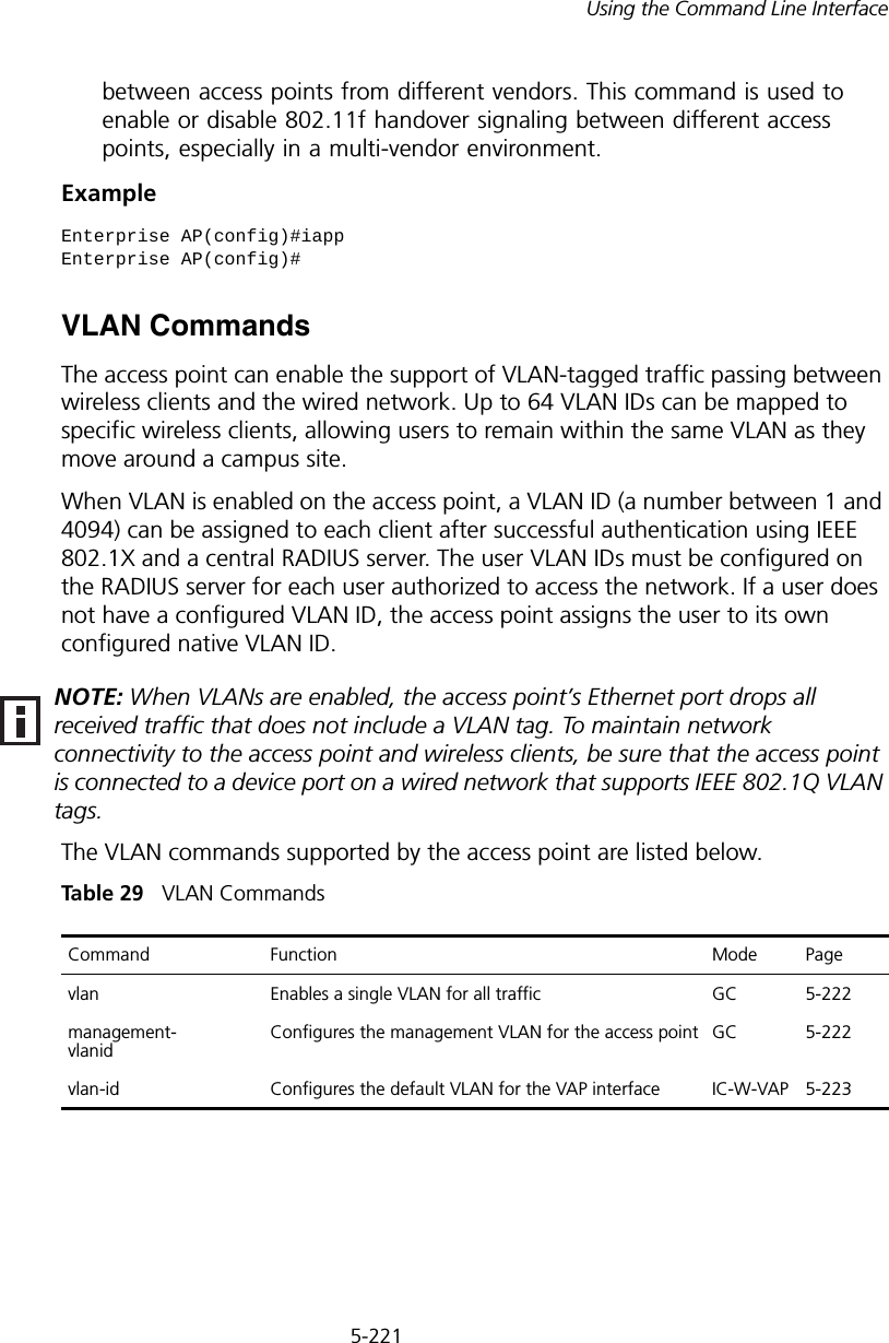
![5-222CHAPTER 5: COMMAND LINE INTERFACEvlanThis command enables VLANs for all traffic. Use the no form to disable VLANs.Syntax[no] vlan enable DefaultDisabledCommand ModeGlobal ConfigurationCommand Description• When VLANs are enabled, the access point tags frames received from wireless clients with the VLAN ID configured for each client on the RADIUS server. If the VLAN ID has not been configured for a client on the RADIUS server, then the frames are tagged with the access point’s native VLAN ID.• Traffic entering the Ethernet port must be tagged with a VLAN ID that matches the access point’s native VLAN ID, or with a VLAN tag that matches one of the wireless clients currently associated with the access point.ExampleRelated Commandsmanagement-vlanid (5-222)management-vlanid This command configures the management VLAN ID for the access point. Syntaxmanagement-vlanid <vlan-id>vlan-id - Management VLAN ID. (Range: 1-4094)Enterprise AP(config)#vlan enableReboot system now? <y/n>: y](https://usermanual.wiki/Hewlett-Packard-Enterprise/WL546.Users-Manual2/User-Guide-670090-Page-150.png)
![5-224CHAPTER 5: COMMAND LINE INTERFACE• If the VLAN ID has not been configured for a client on the RADIUS server, then the frames are tagged with the default VLAN ID of the VAP interface.ExampleWMM CommandsThe access point implements QoS using the Wi-Fi Multimedia (WMM) standard. Using WMM, the access point is able to prioritize traffic and optimize performance when multiple applications compete for wireless network bandwidth at the same time. WMM employs techniques that are a subset of the developing IEEE 802.11e QoS standard and it enables the access point to inter-operate with both WMM- enabled clients and other devices that may lack any WMM functionality.The WMM commands supported by the access point are listed below.Tabl e 30 WMM Commands wmmThis command sets the WMM operational mode on the access point. Use the no form to disable WMM.Syntax[no] wmm <supported | required> •supported - WMM will be used for any associated device that supports this feature. Devices that do not support this feature may still associate with the access point. •required - WMM must be supported on any device trying to associated with the access point. Devices that do not support this feature will not be allowed to associate with the access point. Enterprise AP(if-wireless g: VAP[0])#vlan-id 3Enterprise AP(if-wireless g: VAP[0])#Command Function Mode Pagewmm Sets the WMM operational mode on the access point IC-W 5-224wmm-acknowledge- policyAllows the acknowledgement wait time to be enabled or disabled for each Access Category (AC)IC-W 5-225wmmparam Configures detailed WMM parameters that apply to the access point (AP) or the wireless clients (BSS) IC-W 5-226](https://usermanual.wiki/Hewlett-Packard-Enterprise/WL546.Users-Manual2/User-Guide-670090-Page-152.png)