Hewlett Packard Enterprise WL560 11a/b/g Wireless Workgroup Bridge User Manual NighthawkQSG
Hewlett-Packard Company 11a/b/g Wireless Workgroup Bridge NighthawkQSG
UserManual.wiki
>
Hewlett Packard Enterprise
>
WL560 User Manual
Preliminary Manuals
Navigation menu
Upload a User Manual
Namespaces
Wiki Guide
HTML
PDF
Info
Views
User Manual
Discussion / Help
Navigation
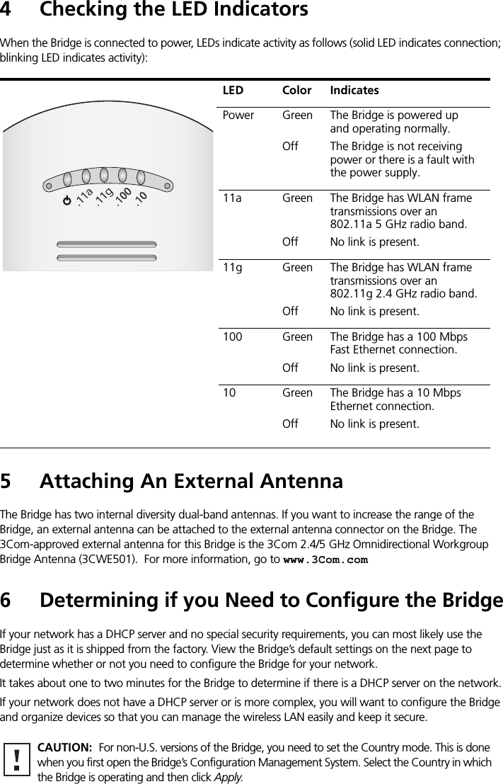
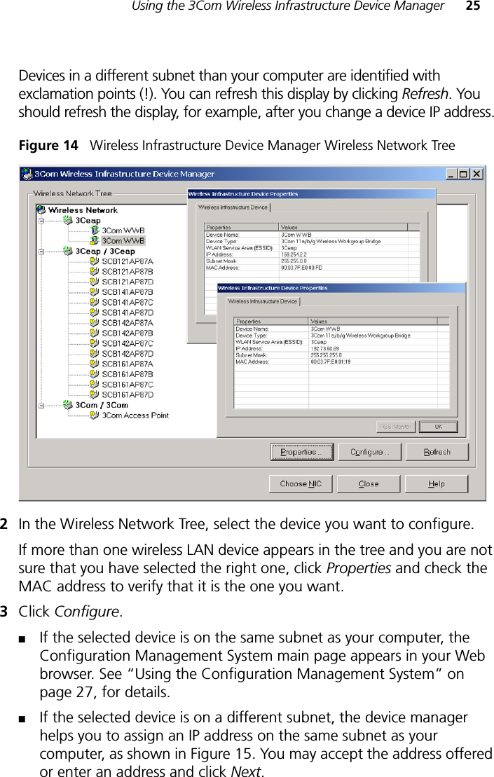
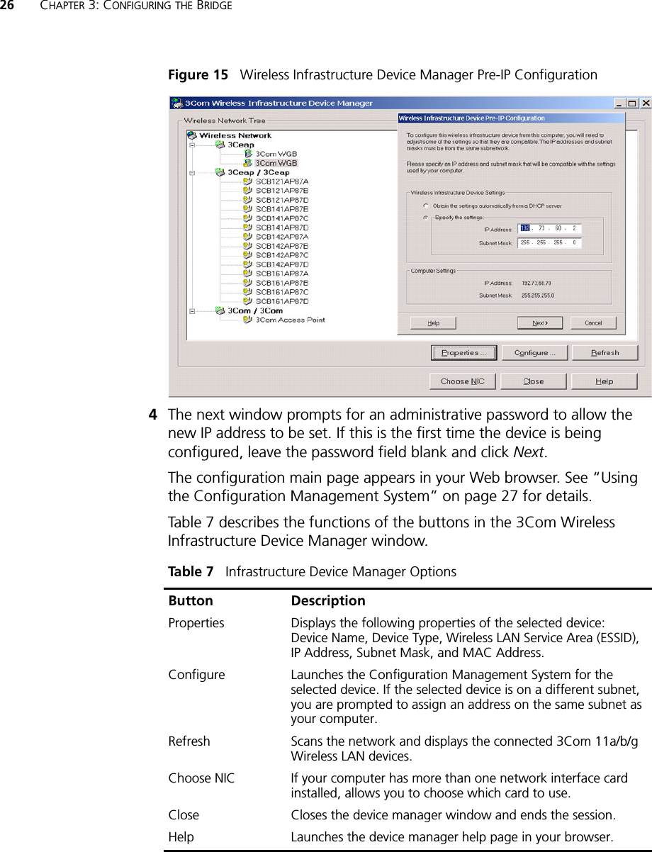
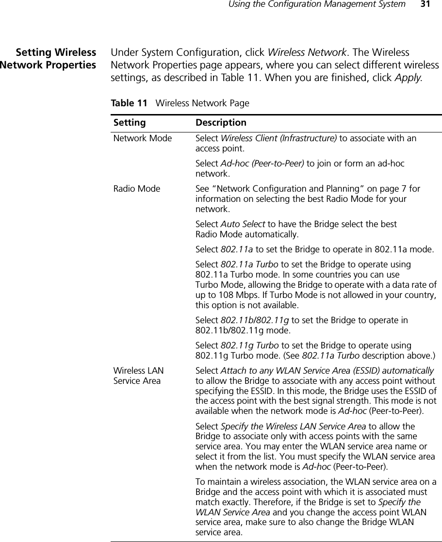
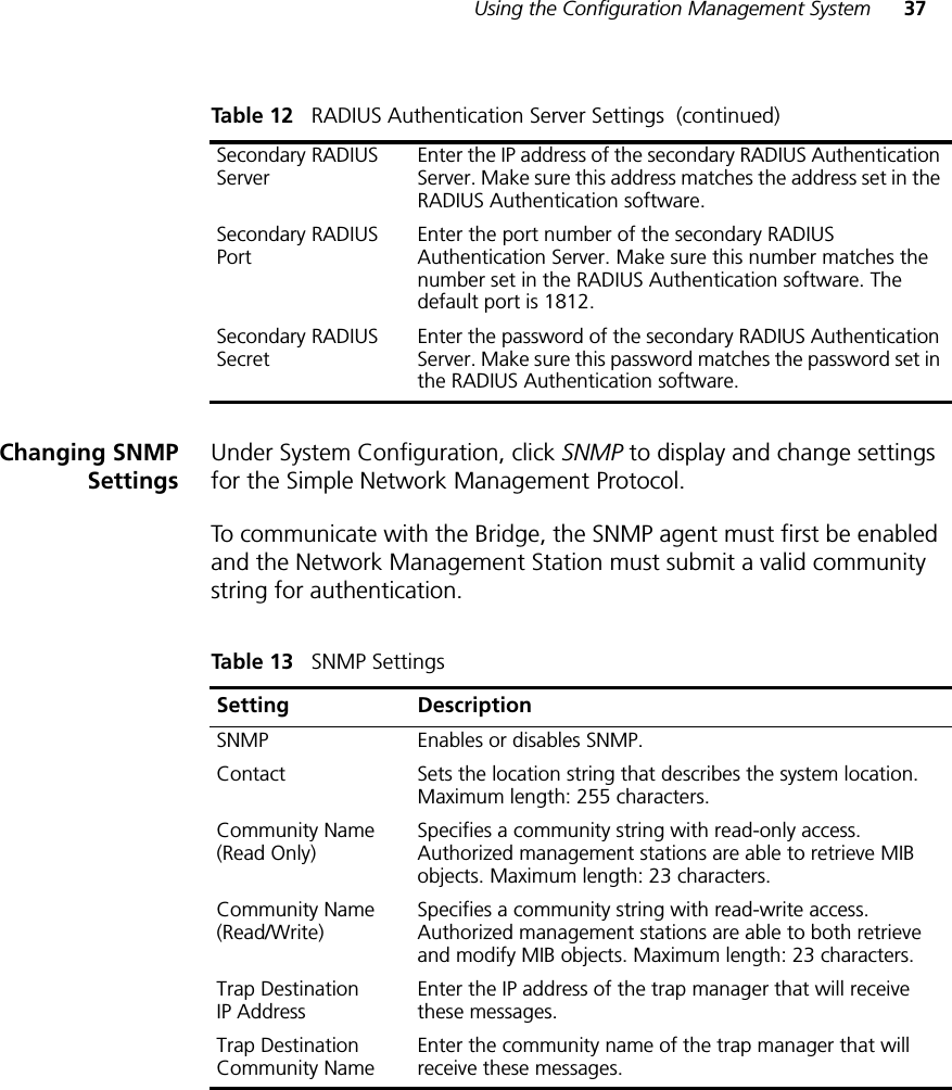
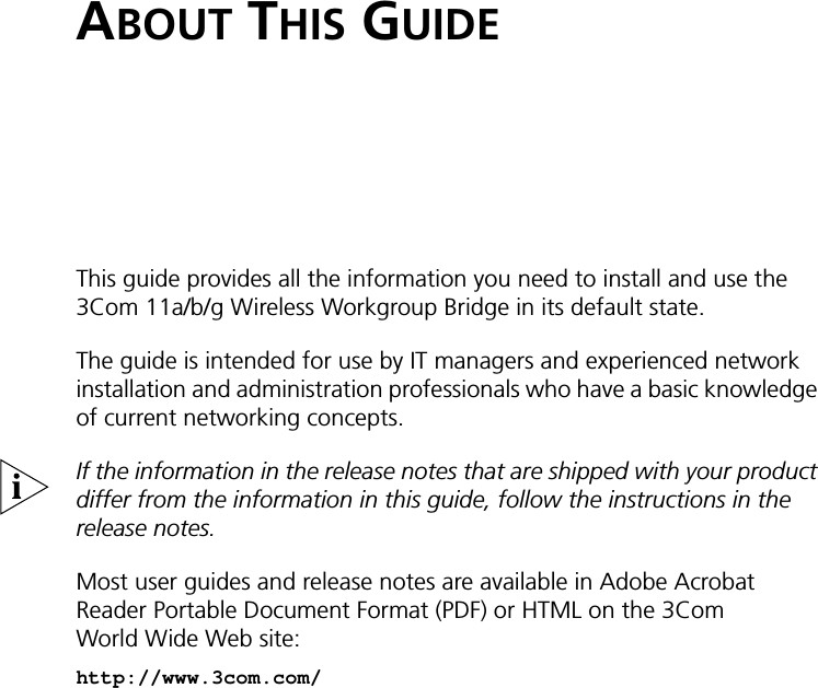
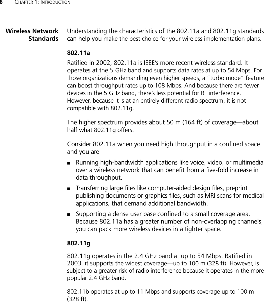
![Copyright © 2004 3Com Corporation. All rights reserved. 3Com and the 3Com logo are registered trademarks of 3Com Corporation. All other company and product names may be trademarks of the respective companies with which they are associated.DQA6750-75AAA01Published July 20047 Using the 3Com Installation CDThe 3Com Installation CD contains the following tools and utilities:■3Com Wireless Infrastructure Device Manager—an administration tool that helps you select 3Com wireless LAN devices and launch their configurations in your Web browser.■3Com 3CDaemon Server Tool—a firmware upgrade tool that can act as a TFTP Server, a SysLog Server, an optional TFTP Client, or an optional FTP Server.To use the 3Com Installation CD, you need a computer running Internet Explorer (latest version is recommended) and one of the following operating systems: Windows XP, Windows 2000, Windows NT 4.0, Windows Me, or Windows 98.To install one of the tools on your computer:1Turn on the computer.2Insert the 3Com Installation CD in the CD-ROM drive.The setup menu appears. If it does not appear, you can start the setup menu from the Windows Start menu. For example: Start > Run > d:setup.exe.3In the menu, click Tools and Utilities.4In the next screen, click the tool you want to install.5Follow the instructions on the screens to complete the installation.Reboot the computer if prompted to do so.6Launch the tool from the Windows Start menu.For details on using the Wireless Infrastructure Device Manager, see “Using the 3Com Wireless Infrastructure Device Manager” in the 3Com 11 a/b/g Wireless Workgroup Bridge User Guide.For instructions on using the 3CDaemon Server Tool, see the application’s online help.Antenna Selection InternalData Preamble Long (if Network Mode is set to Ad-Hoc)Same as access point setting (if Network Mode is set to Wireless Client [Infrastructure])Security Setting Open System (no security)802.1x Authentication State DisabledSNMP EnabledAdministration Login Name adminAdministration Password None (blank)TFTP Server IP Address NoneFTP Server IP Address None](https://usermanual.wiki/Hewlett-Packard-Enterprise/WL560/User-Guide-461162-Page-8.png)

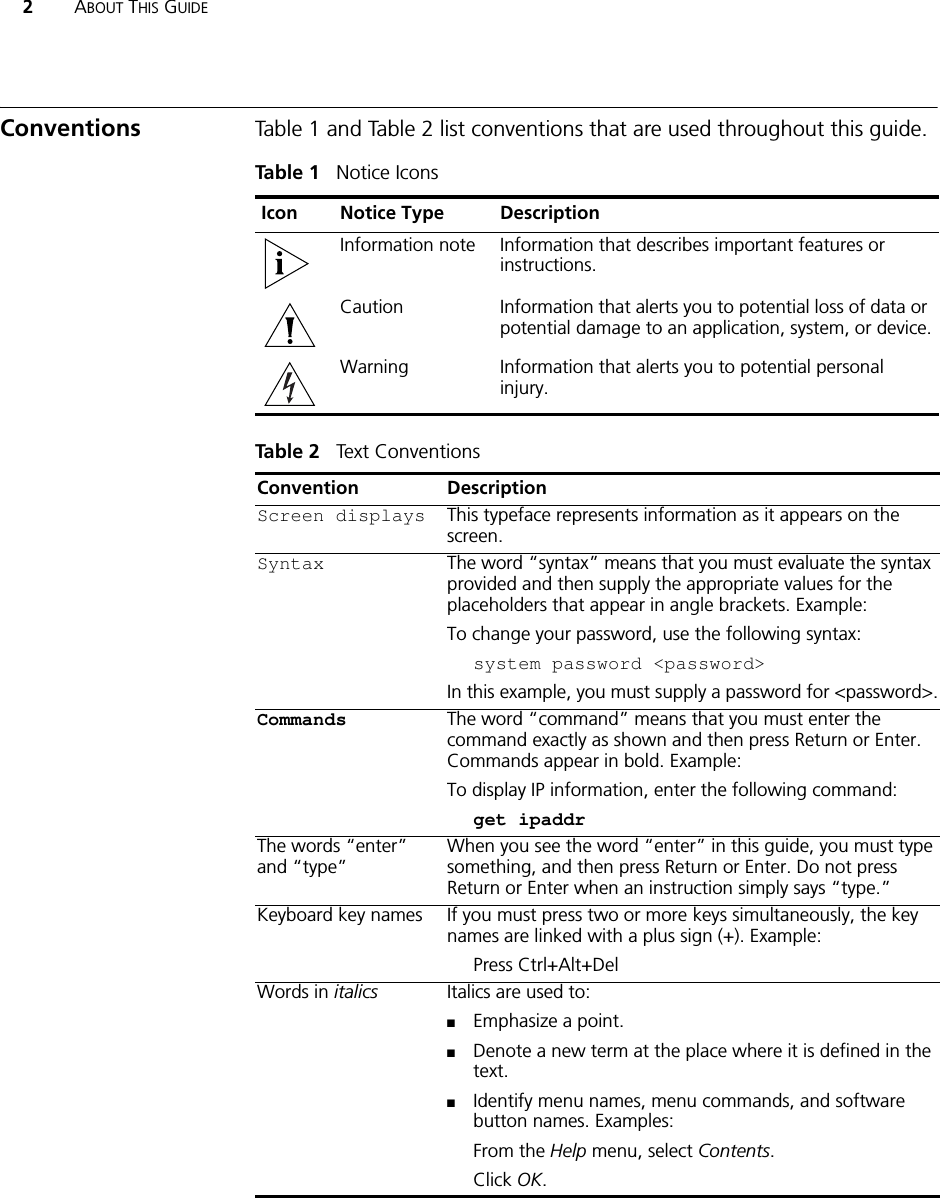

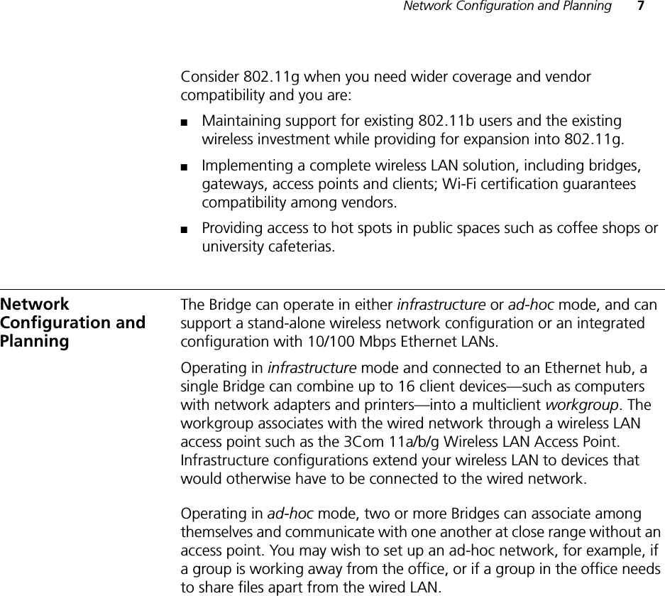
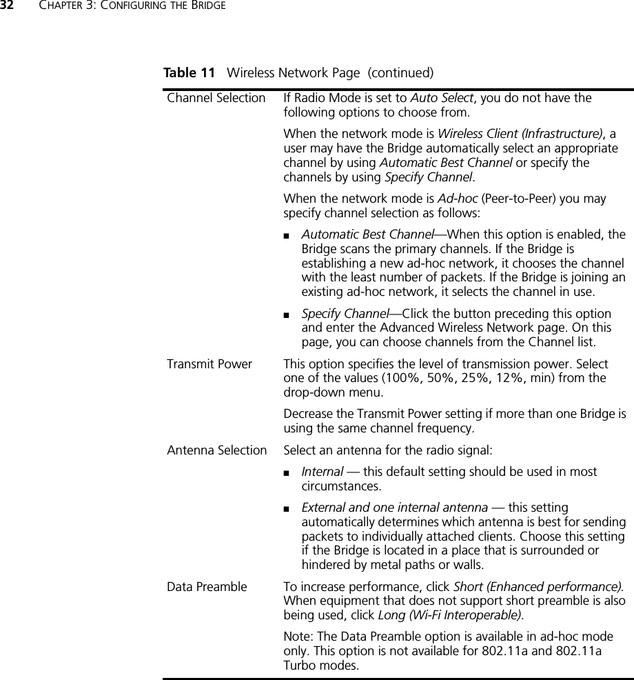
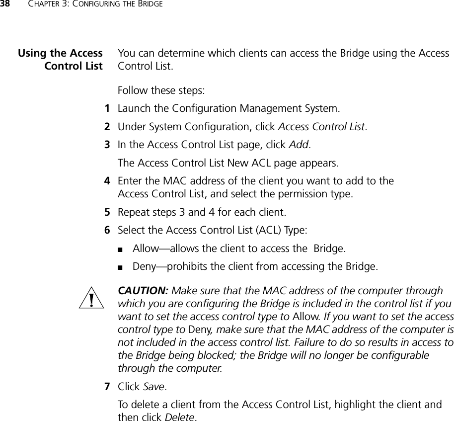
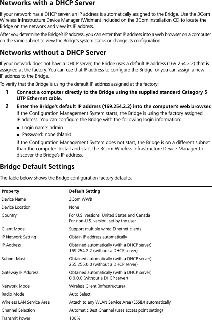
![20 CHAPTER 2: INSTALLING THE BRIDGEBridge Default SettingsTable 4 shows the Bridge configuration factory defaults.Table 4 Factory Default SettingsProperty Default SettingDevice Name 3Com WWBDevice Location NoneCountry For U.S. versions, United States and CanadaFor non-U.S. version, set by the userClient Mode Support multiple wired Ethernet clientsIP Network Setting Obtain IP address automatically IP Address Obtained automatically (with a DHCP server)169.254.2.2 (without a DHCP server)Subnet Mask Obtained automatically (with a DHCP server)255.255.0.0 (without a DHCP server)Gateway IP Address Obtained automatically (with a DHCP server)0.0.0.0 (without a DHCP server)Network Mode Wireless Client (Infrastructure)Radio Mode Auto SelectWireless LAN Service Area Attach to any WLAN Service Area (ESSID) automaticallyChannel Selection Automatic Best Channel (uses access point setting)Transmit Power 100%Antenna Selection InternalData Preamble Long (if Network Mode is set to Ad-Hoc)Same as access point setting (if Network Mode is set to Wireless Client [Infrastructure])Security Setting Open System (no security)802.1x Authentication State DisabledSNMP EnabledAdministration Login Name adminAdministration Password None (blank)TFTP Server IP Address NoneFTP Server IP Address None](https://usermanual.wiki/Hewlett-Packard-Enterprise/WL560/User-Guide-461162-Page-34.png)