Hewlett Packard Enterprise WL561 3COM WIRELESS 7760 11a/b/g POE ACCESS POINT User Manual KoalaQSG
Hewlett-Packard Company 3COM WIRELESS 7760 11a/b/g POE ACCESS POINT KoalaQSG
Contents
- 1. users manual 1
- 2. users manual 2
- 3. users manual 3
- 4. users manual
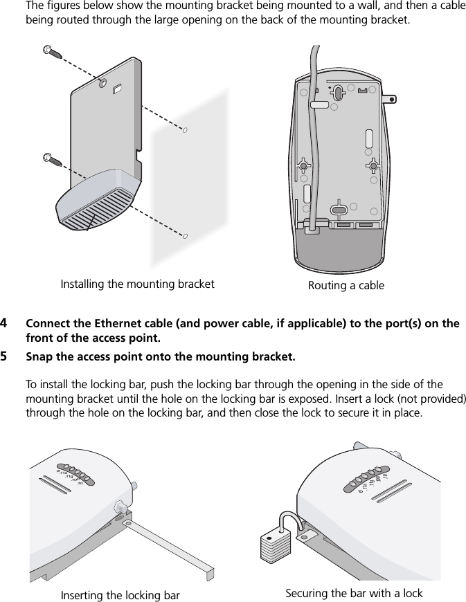
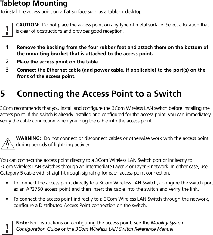
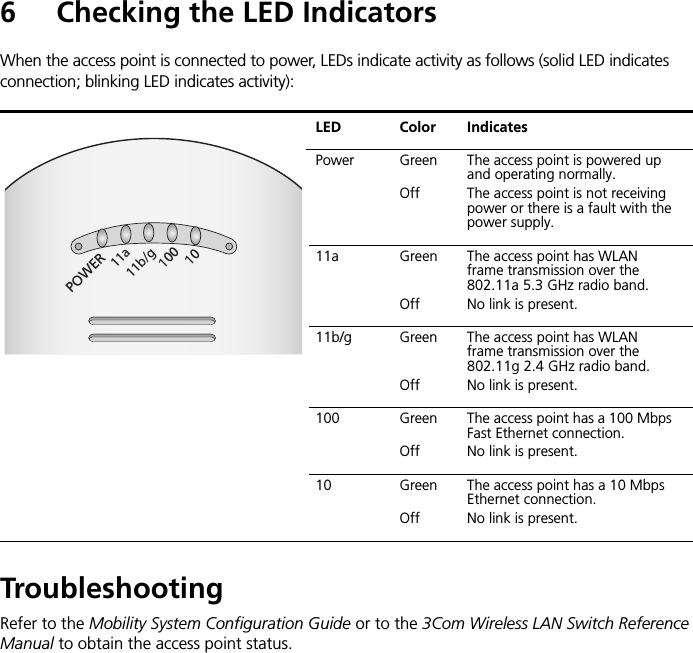
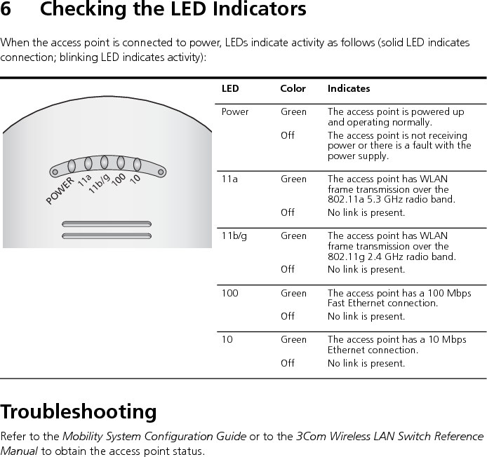
users manual