Hewlett Packard Enterprise WL561 3COM WIRELESS 7760 11a/b/g POE ACCESS POINT User Manual KoalaQSG
Hewlett-Packard Company 3COM WIRELESS 7760 11a/b/g POE ACCESS POINT KoalaQSG
Contents
- 1. users manual 1
- 2. users manual 2
- 3. users manual 3
- 4. users manual
users manual

Quick Start Guide
AP2750 Managed Access Point
3CRWX275075A
The 3Com AP2750 Managed Access Point provides IEEE 802.11a or 802.11b/g wireless access to the
network. The access point is designed for use with a 3Com Wireless LAN Switch, and requires
hardware installation only. All configuration for the access point takes place on the 3Com Wireless
LAN Switch.
You must have a wireless switch device to operate the access point. Two WLAN switch devices can be
connected to the access point:
• 3Com WX4400
• 3Com WX1200
Power can be supplied via Power Over Ethernet (PoE) or by an external power supply. Four 3Com PoE
devices supply power to the access point:
• 3Com PoE Injector
• 3Com 4400PWR PoE Switch
• 3Com Multi-port PoE power supply
• 3Com WX1200
About This Guide
This Quick Start Guide describes the basic installation of the access point. It covers the following topics:
•3Com AP2750 Managed Access Point Features
•Observing Safety Precautions
•Step 1: Unpacking the Access Point
•Step 2: Preparing for Installation
•Step 3: Attaching the Antennas
•Step 4: Mounting the Access Point
•Step 5: Connecting the Access Point to a Switch
•Step 6: Checking the LED Indicators
•Troubleshooting
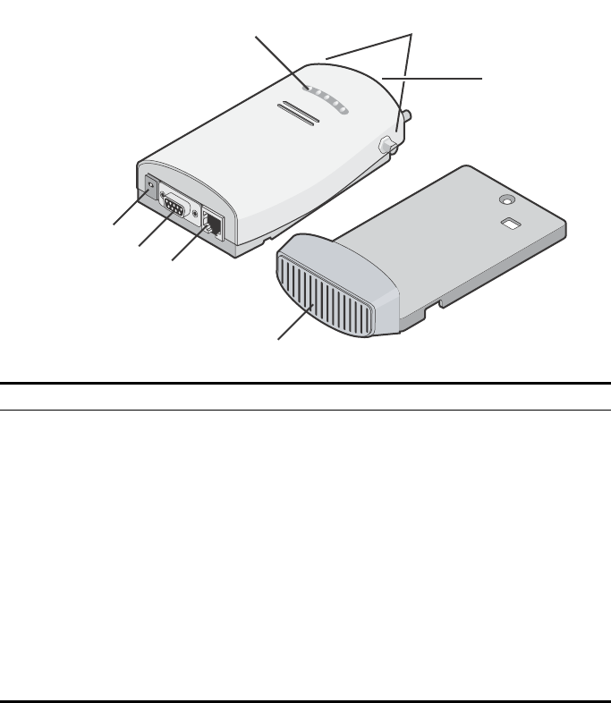
3Com AP2750 Managed Access Point Features
Feature Description
Power Port The access point can be powered either via Power Over Ethernet (PoE), or by an
external power supply (not included) that is plugged into the Power Port.
Serial Port The serial port is not supported.
Ethernet Port The Ethernet port provides a 10/100BASE-TX Ethernet connection to a 3Com Wireless
LAN switch. The connection can be direct to a 3Com switch or indirect through an
intermediate Layer 2 or Layer 3 network.
Use a standard Category 5 cable with straight-through signaling and standard RJ-45
connectors to connect the access point to the switch on the network.
LEDs The LEDs indicate power and activity. See “Checking the LED Indicators” on page 7
for details.
Antenna Connectors Two SMA-female antenna connectors allow you to connect antennas that operate in
2.4 GHz and 5.3 GHz bands.
Reset Button The reset button is accessible from the back of the access point as well as through the
mounting bracket. Push the reset button to restore the access point to its factory
default settings.
Mounting Bracket The mounting bracket comes attached to the access point. This mounting bracket
allows the access point to be mounted to a wall or ceiling.
Power Port
Serial Port
Ethernet Port
Mounting
Bracket
LEDs Antenna
Connectors
Reset
Button

Observing Safety Precautions
This equipment must be installed in compliance with local and national building codes, regulatory
restrictions, and FCC rules. For the safety of people and equipment, only professional network personnel
should install the access point.
1 Unpacking the Access Point
Make sure that you have the following items, which are included with the access point:
• Two external 2.4 GHz and 5.3 GHz dual-band antennas
• Mounting bracket (attached to the access point)
• Wall-mounting hardware:
•Locking bar (used for securing a wall- or ceiling-mounted installation)
•Two sheet metal screws
•Two thread screws
•Two wall anchors
• Four adhesive rubber feet (used for a flat-surface installation).
2 Preparing for Installation
It is advisable to connect the power (if using an external power supply) and check the Ethernet cables
and LEDs before installing the access point in a hard-to-reach location. Additionally, observe the
following items before mounting or connecting the access point:
WARNING: To comply with FCC radio frequency (RF) exposure limits, a minimum body-to-
antenna distance of 20 cm (8 in.) must be maintained when the access point is operational.
WARNING: To avoid possible injury or damage to equipment, you must use power supply equipment
that is safety certified according to UL, CSA, IEC, or other applicable national or international safety
requirements for the country of use. All references to power supply in this document refer to equipment
meeting these requirements.
Installation Item Description
Switch port 3Com recommends that you install and configure the 3Com Wireless LAN switch
before installing the access point. Set the port type on the switch to an AP2750
access point.
Cabling Make sure that standard Category 5 cable with straight-through signaling is
installed at the site before you install the access point.
Make sure that the cable is highly flexible and that there is no extra covering on the
RJ-45 connector that could prevent the cable from being routed through the
mounting bracket.
Power Requirements Power can be supplied via an 802.3af Power Over Ethernet (PoE)-compliant device
or by an external power supply with a minimum 5v @ 2.0 amp.
If using an external power supply, make sure the power outlet is accessible. The
power supply plug is the only means of disconnecting the access point from power.
MAC Address Record the access point MAC address in a safe place before the access point is
installed in a hard-to-reach location.
The MAC address is printed on the back of the access point. Additional MAC
address labels are shipped with the access point.

3 Attaching the Antennas
Carefully unpack the standard detachable antennas. Screw the antennas on to the antenna connectors
on the access point and hand-tighten them. After network startup, you may need to adjust the antennas
to fine-tune coverage in your area.
For best results, adjust the antennas so that they are perpendicular with the floor and ceiling.
4 Mounting the Access Point
The access point can be mounted on the following types of surfaces:
• Wall, ceiling, or electrical box (NEMA enclosure)
•Tabletop
.
Wall, Ceiling, or Electrical Box Mounting
To mount the access point to a wall, ceiling, or electrical box:
1Remove the access point from the mounting bracket.
2Screw the mounting bracket to a wall, ceiling, or electrical box (NEMA enclosure):
•If mounting to a solid surface wall or ceiling, use the two sheet metal screws.
•If mounting to drywall, use the two sheet metal screws and two wall anchors.
•If mounting to an electrical box (NEMA enclosure), use the two threaded screws.
3Route the power cable (if using an external power supply) and Ethernet cable
through the large opening on the back of the mounting bracket.
.
CAUTION: Do not handle the antenna tips, especially after they are connected to the access
point. This could lead to electrostatic discharge (ESD), which could damage the equipment.
CAUTION: The access point is intended for indoor use only. Do not install the access point
outdoors unless you install it in a properly installed outdoor access point enclosure.
CAUTION: For easy installation and removal of the access point from the mounting
bracket, make sure that there is sufficient flexibility with the cable and that there is
adequate service loop (that is, enough cable routed through the mounting bracket
to easily connect the cable to the access point.) If not enough cable is routed
through the back of the mounting bracket, or if the cable is inflexible, it can be
difficult to install or remove the access point from the mounting bracket.
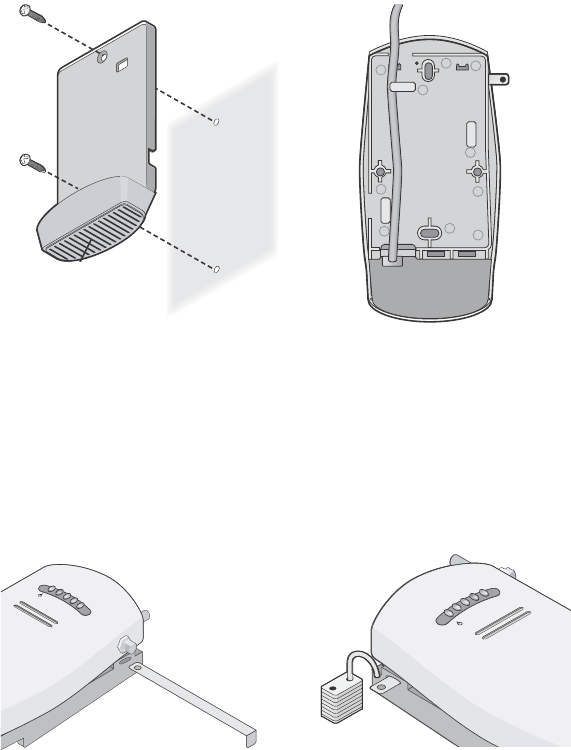
The figures below show the mounting bracket being mounted to a wall, and then a cable
being routed through the large opening on the back of the mounting bracket.
4Connect the Ethernet cable (and power cable, if applicable) to the port(s) on the
front of the access point.
5Snap the access point onto the mounting bracket.
To install the locking bar, push the locking bar through the opening in the side of the
mounting bracket until the hole on the locking bar is exposed. Insert a lock (not provided)
through the hole on the locking bar, and then close the lock to secure it in place.
Installing the mounting bracket Routing a cable
C
r
a
dl
e
Inserting the locking bar Securing the bar with a lock
.11g
.100
.10
.11a
.11g
.100
.10
.11a

Tabletop Mounting
To install the access point on a flat surface such as a table or desktop:
1Remove the backing from the four rubber feet and attach them on the bottom of
the mounting bracket that is attached to the access point.
2Place the access point on the table.
3Connect the Ethernet cable (and power cable, if applicable) to the port(s) on the
front of the access point.
5 Connecting the Access Point to a Switch
3Com recommends that you install and configure the 3Com Wireless LAN switch before installing the
access point. If the switch is already installed and configured for the access point, you can immediately
verify the cable connection when you plug the cable into the access point.
You can connect the access point directly to a 3Com Wireless LAN Switch port or indirectly to
3Com Wireless LAN switches through an intermediate Layer 2 or Layer 3 network. In either case, use
Category 5 cable with straight-through signaling for each access point connection.
• To connect the access point directly to a 3Com Wireless LAN Switch, configure the switch port
as an AP2750 access point and then insert the cable into the switch and verify the link.
• To connect the access point indirectly to a 3Com Wireless LAN Switch through the network,
configure a Distributed Access Point connection on the switch.
CAUTION: Do not place the access point on any type of metal surface. Select a location that
is clear of obstructions and provides good reception.
WARNING: Do not connect or disconnect cables or otherwise work with the access point
during periods of lightning activity.
Note: For instructions on configuring the access point, see the Mobility System
Configuration Guide or the 3Com Wireless LAN Switch Reference Manual.
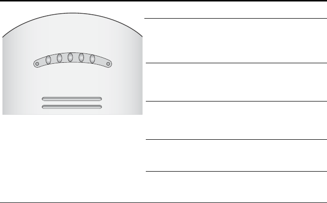
6 Checking the LED Indicators
When the access point is connected to power, LEDs indicate activity as follows (solid LED indicates
connection; blinking LED indicates activity):
Troubleshooting
Refer to the Mobility System Configuration Guide or to the 3Com Wireless LAN Switch Reference
Manual to obtain the access point status.
LED Color Indicates
Power Green
Off
The access point is powered up
and operating normally.
The access point is not receiving
power or there is a fault with the
power supply.
11a Green
Off
The access point has WLAN
frame transmission over the
802.11a 5.3 GHz radio band.
No link is present.
11b/g Green
Off
The access point has WLAN
frame transmission over the
802.11g 2.4 GHz radio band.
No link is present.
100 Green
Off
The access point has a 100 Mbps
Fast Ethernet connection.
No link is present.
10 Green
Off
The access point has a 10 Mbps
Ethernet connection.
No link is present.
11b/g
11a
POWER
100
10

Copyright © 2004 3Com Corporation. All rights reserved. 3Com and the 3Com logo are registered
trademarks of 3Com Corporation. All other company and product names may be trademarks of the
respective companies with which they are associated.
DIA27507-5AAA01
Published October 2004
FEDERAL COMMUNICATIONS COMMISSION
This device complies with Part 15 of the FCC Rules. Operation is subject to the
following two conditions:(1) this device may not cause harmful interference, and (2)
this device must accept any interference received, including interference that may
cause undesired operation.
Changes or modifications not expressly approved by the party responsible for
compliance could void the user‘s authority to operate the equipment.
NOTE
This equipment has been tested and found to comply with the limits for a Class B
digital device, pursuant to Part 15 of the FCC Rules. These limits are designed to
provide reasonable protection against harmful interference in a residential installation.
This equipment generates, uses and can radiated radio frequency energy and, if not
installed and used in accordance with the instructions, may cause harmful interference
to radio communications. However, there is no guarantee that interference will not
occur in a particular installation If this equipment does cause harmful interference to
radio or television reception, which can be determined by turning the equipment off
and on, the user is encouraged to try to correct the interference by one or more of the
following measures:
-Reorient or relocate the receiving antenna.
-Increase the separation between the equipment and receiver.
-Connect the equipment into an outlet on a circuit different from that to which the
receiver is connected.
-Consult the dealer or an experienced radio/TV technician for help.
Note:
This device and its antenna(s) used for this transmitter must not be co-located or
operating in conjunction with any other antenna or transmitter.
This equipment complies with FCC radiation exposure limits set forth for an
uncontrolled environment. In order to avoid the possibility of exceeding the FCC
radio frequency exposure limits, human proximity to the antenna shall not be less than
20cm (8 inches) during normal operation.
According to 15.407(e):
If this device is going to be operated in 5.15 ~ 5.25GHz frequency range, then it is
restricted in indoor environment only.
RSS-GEN-7.1.4 Transmitter Antenna:
To reduce potential radio interference to other users, the antenna type and its gain of 8dBi.
should be so chosen that the equivalent isotropically radiated power (EIRP) is not more
than that required for successful communication.
This device has been designed to operate with an antenna having a maximum gain.
Antenna haveing a higher gain is strictly prohibited per regulations of industry
Canada. The required antenna impedance is 50 ohms.
To reduce potential radio interference to other users, the antenna type and its gain should
be so chosen that the equivalent isotropically radiated power (e.i.r.p.) is not more than
that permitted for successful communication.