Hewlett Packard Enterprise WL561 3COM WIRELESS 7760 11a/b/g POE ACCESS POINT User Manual KoalaQSG
Hewlett-Packard Company 3COM WIRELESS 7760 11a/b/g POE ACCESS POINT KoalaQSG
Contents
- 1. users manual 1
- 2. users manual 2
- 3. users manual 3
- 4. users manual
users manual 1

Quick Start Guide
AP2750 Managed Access Point
3CRWX275075A
The 3Com AP2750 Managed Access Point provides IEEE 802.11a or 802.11b/g wireless access to the
network. The access point is designed for use with a 3Com Wireless LAN Switch, and requires
hardware installation only. All configuration for the access point takes place on the 3Com Wireless
LAN Switch.
You must have a wireless switch device to operate the access point. Two WLAN switch devices can be
connected to the access point:
• 3Com WX4400
• 3Com WX1200
Power can be supplied via Power Over Ethernet (PoE) or by an external power supply. Four 3Com PoE
devices supply power to the access point:
• 3Com PoE Injector
• 3Com 4400PWR PoE Switch
• 3Com Multi-port PoE power supply
• 3Com WX1200
About This Guide
This Quick Start Guide describes the basic installation of the access point. It covers the following topics:
•3Com AP2750 Managed Access Point Features
•Observing Safety Precautions
•Step 1: Unpacking the Access Point
•Step 2: Preparing for Installation
•Step 3: Attaching the Antennas
•Step 4: Mounting the Access Point
•Step 5: Connecting the Access Point to a Switch
•Step 6: Checking the LED Indicators
•Troubleshooting
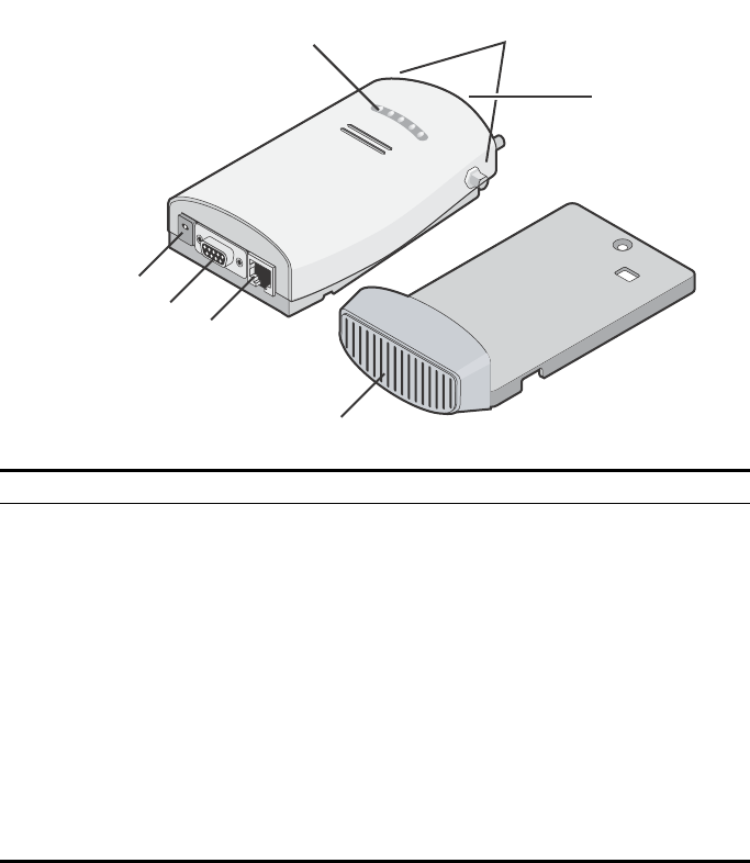
3Com AP2750 Managed Access Point Features
Feature Description
Power Port The access point can be powered either via Power Over Ethernet (PoE), or by an
external power supply (not included) that is plugged into the Power Port.
Serial Port The serial port is not supported.
Ethernet Port The Ethernet port provides a 10/100BASE-TX Ethernet connection to a 3Com Wireless
LAN switch. The connection can be direct to a 3Com switch or indirect through an
intermediate Layer 2 or Layer 3 network.
Use a standard Category 5 cable with straight-through signaling and standard RJ-45
connectors to connect the access point to the switch on the network.
LEDs The LEDs indicate power and activity. See “Checking the LED Indicators” on page 7
for details.
Antenna Connectors Two SMA-female antenna connectors allow you to connect antennas that operate in
2.4 GHz and 5.3 GHz bands.
Reset Button The reset button is accessible from the back of the access point as well as through the
mounting bracket. Push the reset button to restore the access point to its factory
default settings.
Mounting Bracket The mounting bracket comes attached to the access point. This mounting bracket
allows the access point to be mounted to a wall or ceiling.
Power Port
Serial Port
Ethernet Port
Mounting
Bracket
LEDs Antenna
Connectors
Reset
Button

Observing Safety Precautions
This equipment must be installed in compliance with local and national building codes, regulatory
restrictions, and FCC rules. For the safety of people and equipment, only professional network personnel
should install the access point.
1 Unpacking the Access Point
Make sure that you have the following items, which are included with the access point:
• Two external 2.4 GHz and 5.3 GHz dual-band antennas
• Mounting bracket (attached to the access point)
• Wall-mounting hardware:
•Locking bar (used for securing a wall- or ceiling-mounted installation)
•Two sheet metal screws
•Two thread screws
•Two wall anchors
• Four adhesive rubber feet (used for a flat-surface installation).
2 Preparing for Installation
It is advisable to connect the power (if using an external power supply) and check the Ethernet cables
and LEDs before installing the access point in a hard-to-reach location. Additionally, observe the
following items before mounting or connecting the access point:
WARNING: To comply with FCC radio frequency (RF) exposure limits, a minimum body-to-
antenna distance of 20 cm (8 in.) must be maintained when the access point is operational.
WARNING: To avoid possible injury or damage to equipment, you must use power supply equipment
that is safety certified according to UL, CSA, IEC, or other applicable national or international safety
requirements for the country of use. All references to power supply in this document refer to equipment
meeting these requirements.
Installation Item Description
Switch port 3Com recommends that you install and configure the 3Com Wireless LAN switch
before installing the access point. Set the port type on the switch to an AP2750
access point.
Cabling Make sure that standard Category 5 cable with straight-through signaling is
installed at the site before you install the access point.
Make sure that the cable is highly flexible and that there is no extra covering on the
RJ-45 connector that could prevent the cable from being routed through the
mounting bracket.
Power Requirements Power can be supplied via an 802.3af Power Over Ethernet (PoE)-compliant device
or by an external power supply with a minimum 5v @ 2.0 amp.
If using an external power supply, make sure the power outlet is accessible. The
power supply plug is the only means of disconnecting the access point from power.
MAC Address Record the access point MAC address in a safe place before the access point is
installed in a hard-to-reach location.
The MAC address is printed on the back of the access point. Additional MAC
address labels are shipped with the access point.