Hewlett Packard Enterprise WL561 3COM WIRELESS 7760 11a/b/g POE ACCESS POINT User Manual KoalaQSG
Hewlett-Packard Company 3COM WIRELESS 7760 11a/b/g POE ACCESS POINT KoalaQSG
Contents
- 1. users manual 1
- 2. users manual 2
- 3. users manual 3
- 4. users manual
users manual 2

3 Attaching the Antennas
Carefully unpack the standard detachable antennas. Screw the antennas on to the antenna connectors
on the access point and hand-tighten them. After network startup, you may need to adjust the antennas
to fine-tune coverage in your area.
For best results, adjust the antennas so that they are perpendicular with the floor and ceiling.
4 Mounting the Access Point
The access point can be mounted on the following types of surfaces:
• Wall, ceiling, or electrical box (NEMA enclosure)
•Tabletop
.
Wall, Ceiling, or Electrical Box Mounting
To mount the access point to a wall, ceiling, or electrical box:
1Remove the access point from the mounting bracket.
2Screw the mounting bracket to a wall, ceiling, or electrical box (NEMA enclosure):
•If mounting to a solid surface wall or ceiling, use the two sheet metal screws.
•If mounting to drywall, use the two sheet metal screws and two wall anchors.
•If mounting to an electrical box (NEMA enclosure), use the two threaded screws.
3Route the power cable (if using an external power supply) and Ethernet cable
through the large opening on the back of the mounting bracket.
.
CAUTION: Do not handle the antenna tips, especially after they are connected to the access
point. This could lead to electrostatic discharge (ESD), which could damage the equipment.
CAUTION: The access point is intended for indoor use only. Do not install the access point
outdoors unless you install it in a properly installed outdoor access point enclosure.
CAUTION: For easy installation and removal of the access point from the mounting
bracket, make sure that there is sufficient flexibility with the cable and that there is
adequate service loop (that is, enough cable routed through the mounting bracket
to easily connect the cable to the access point.) If not enough cable is routed
through the back of the mounting bracket, or if the cable is inflexible, it can be
difficult to install or remove the access point from the mounting bracket.
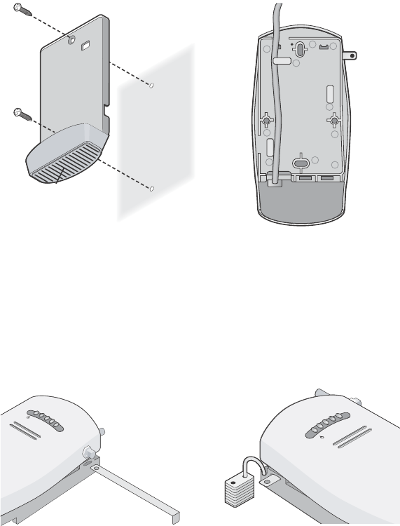
The figures below show the mounting bracket being mounted to a wall, and then a cable
being routed through the large opening on the back of the mounting bracket.
4Connect the Ethernet cable (and power cable, if applicable) to the port(s) on the
front of the access point.
5Snap the access point onto the mounting bracket.
To install the locking bar, push the locking bar through the opening in the side of the
mounting bracket until the hole on the locking bar is exposed. Insert a lock (not provided)
through the hole on the locking bar, and then close the lock to secure it in place.
Installing the mounting bracket Routing a cable
C
r
a
dl
e
Inserting the locking bar Securing the bar with a lock
.11g
.100
.10
.11a
.11g
.100
.10
.11a

Tabletop Mounting
To install the access point on a flat surface such as a table or desktop:
1Remove the backing from the four rubber feet and attach them on the bottom of
the mounting bracket that is attached to the access point.
2Place the access point on the table.
3Connect the Ethernet cable (and power cable, if applicable) to the port(s) on the
front of the access point.
5 Connecting the Access Point to a Switch
3Com recommends that you install and configure the 3Com Wireless LAN switch before installing the
access point. If the switch is already installed and configured for the access point, you can immediately
verify the cable connection when you plug the cable into the access point.
You can connect the access point directly to a 3Com Wireless LAN Switch port or indirectly to
3Com Wireless LAN switches through an intermediate Layer 2 or Layer 3 network. In either case, use
Category 5 cable with straight-through signaling for each access point connection.
• To connect the access point directly to a 3Com Wireless LAN Switch, configure the switch port
as an AP2750 access point and then insert the cable into the switch and verify the link.
• To connect the access point indirectly to a 3Com Wireless LAN Switch through the network,
configure a Distributed Access Point connection on the switch.
CAUTION: Do not place the access point on any type of metal surface. Select a location that
is clear of obstructions and provides good reception.
WARNING: Do not connect or disconnect cables or otherwise work with the access point
during periods of lightning activity.
Note: For instructions on configuring the access point, see the Mobility System
Configuration Guide or the 3Com Wireless LAN Switch Reference Manual.