Hewlett Packard Enterprise WL575 Outdoor 11a Building to Building Bridge & 11bg AP User Manual OAP6626A UG 32
Hewlett-Packard Company Outdoor 11a Building to Building Bridge & 11bg AP OAP6626A UG 32
Contents
- 1. Users Manual 1
- 2. Users Manual 2
- 3. Users Manual1
- 4. Users Manual2
Users Manual 1


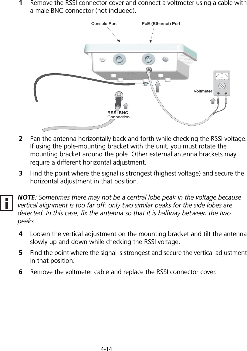
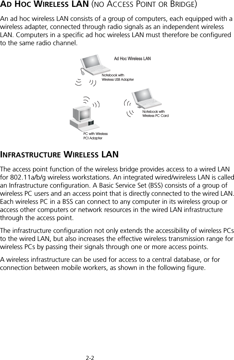
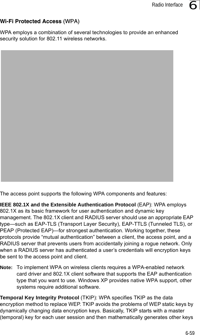
![Initial Configuration5-25Note: When using HyperTerminal with Microsoft® Windows® 2000, make sure that you have Windows 2000 Service Pack 2 or later installed. Windows 2000 Service Pack 2 fixes the problem of arrow keys not functioning in HyperTerminal’s VT100 emulation. See www.microsoft.com for information on Windows 2000 service packs. 4. Once you have set up the terminal correctly, press the [Enter] key to initiate the console connection. The console login screen will be displayed.For a description of how to use the CLI, see “Using the Command Line Interface” on page 7-1. For a list of all the CLI commands and detailed information on using the CLI, refer to “Command Groups” on page 7-6.Initial Configuration StepsLogging In – Enter “admin” for the user name and leave the password blank. The CLI prompt appears displaying the bridge’s name.Setting the IP Address – By default, the bridge is configured to obtain IP address settings from a DHCP server. If a DHCP server is not available, the IP address defaults to 192.168.2.2, which may not be compatible with your network. You will therefore have to use the command line interface (CLI) to assign an IP address that is compatible with your network. Type “configure” to enter configuration mode, then type “interface ethernet” to access the Ethernet interface-configuration mode.First type “no ip dhcp” to disable DHCP client mode. Then type “ip address ip-address netmask gateway,” where “ip-address” is the bridge’s IP address, “netmask” is the network mask for the network, and “gateway” is the default gateway router. Check with your system administrator to obtain an IP address that is compatible with your network.Username: adminPassword: Enterprise AP#Enterprise AP#configureEnterprise AP(config)#interface ethernetEnterprise AP(config-if)#Enterprise AP(if-ethernet)#no ip dhcpEnterprise AP(if-ethernet)#ip address 192.168.2.2 255.255.255.0 192.168.2.254Enterprise AP(if-ethernet)#](https://usermanual.wiki/Hewlett-Packard-Enterprise/WL575.Users-Manual-1/User-Guide-670063-Page-50.png)


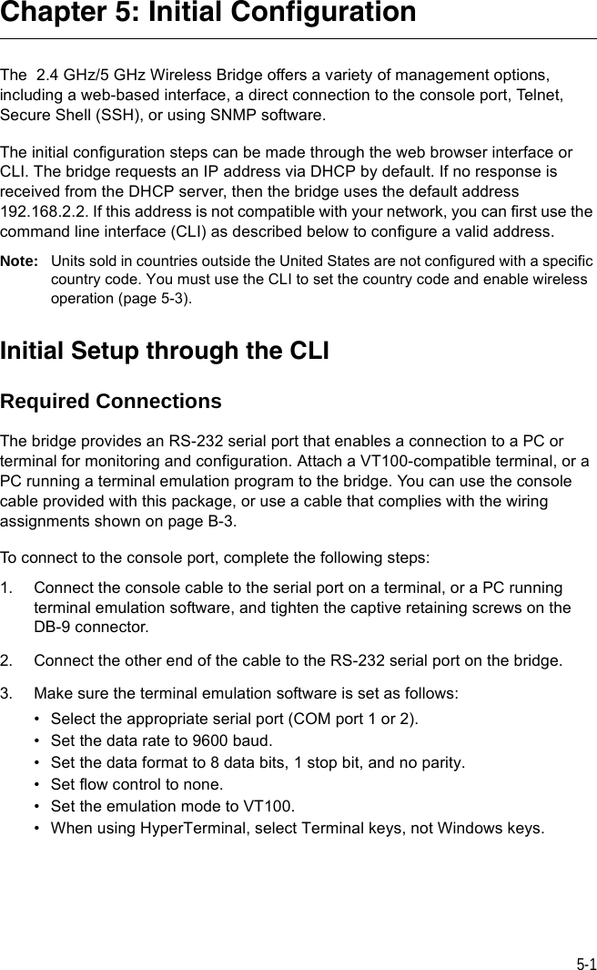
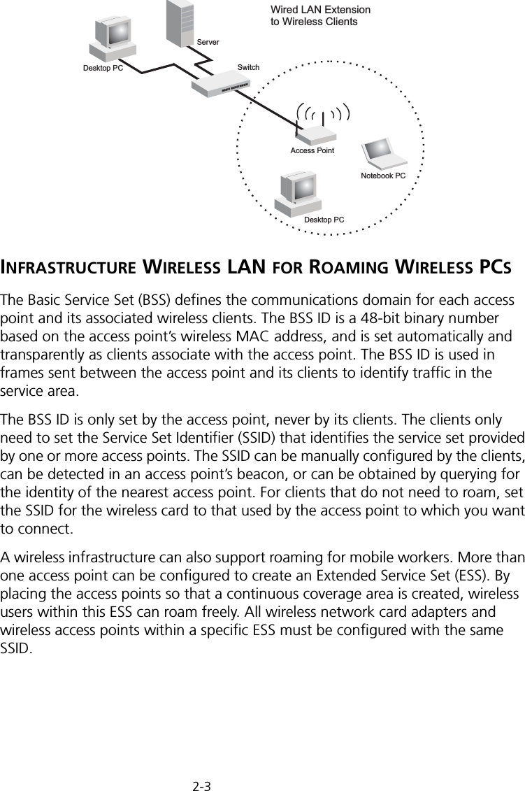
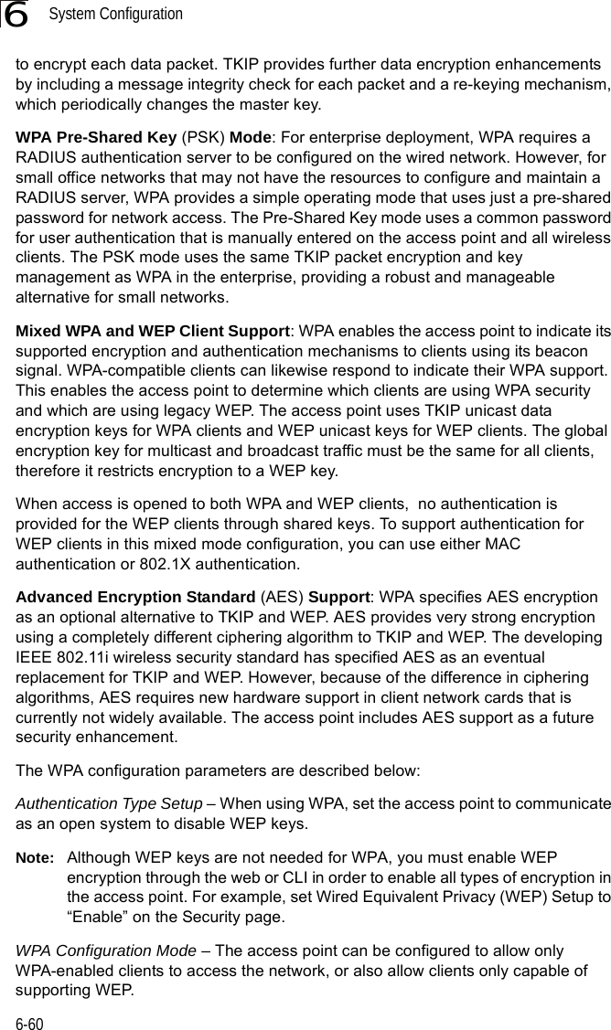
![System Configuration6-266CLI Commands for Downloading Software from a TFTP Server – Use the copy tftp file command from the Exec mode and then specify the file type, name, and IP address of the TFTP server. When the download is complete, the dir command can be used to check that the new file is present in the wireless bridge file system. To run the new software, use the reset board command to reboot the wireless bridge.DUAL OUTDOOR#copy tftp file 6-561. Application image2. Config file3. Boot block imageSelect the type of download<1,2,3>: [1]:1TFTP Source file name:bridge-img.binTFTP Server IP:192.168.1.19DUAL OUTDOOR#dir 6-58File Name Type File Size-------------------------- ---- -----------dflt-img.bin 2 1319939bridge-img.bin 2 1629577syscfg 5 17776syscfg_bak 5 17776 262144 byte(s) availableDUAL OUTDOOR#reset board 6-10Reboot system now? <y/n>: y](https://usermanual.wiki/Hewlett-Packard-Enterprise/WL575.Users-Manual-1/User-Guide-670063-Page-78.png)


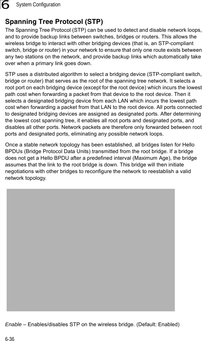
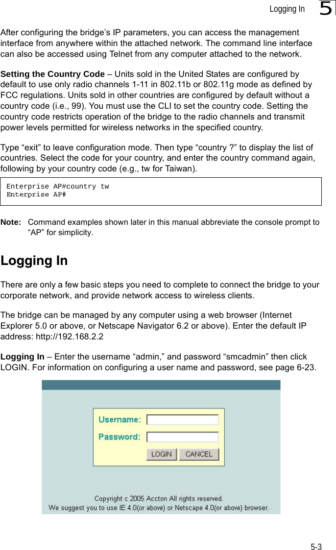
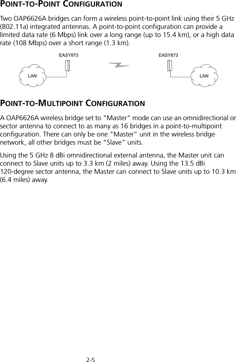
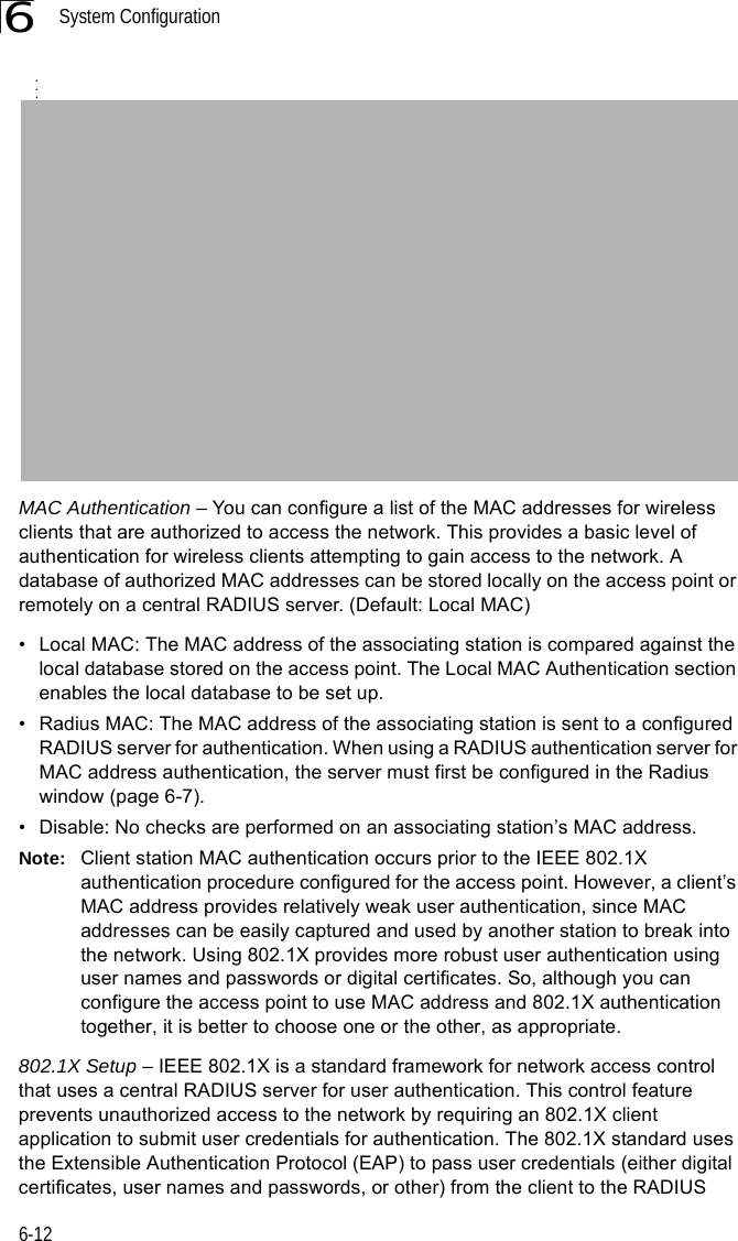
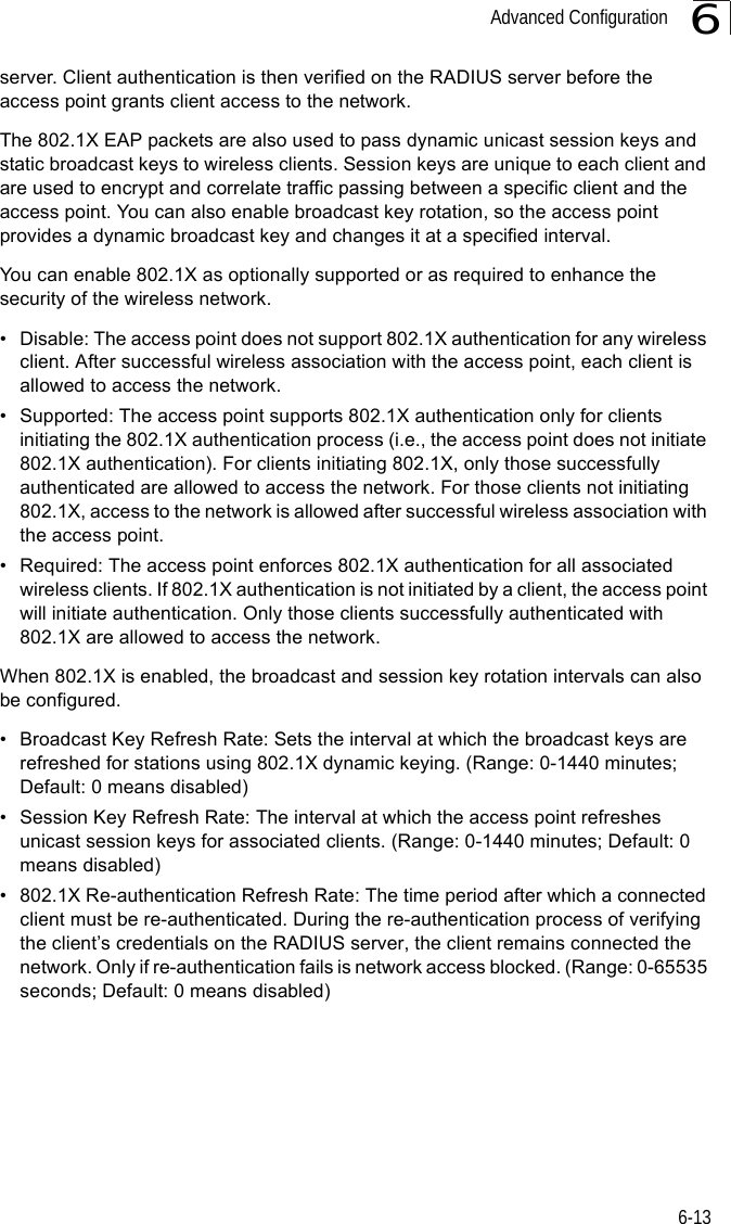
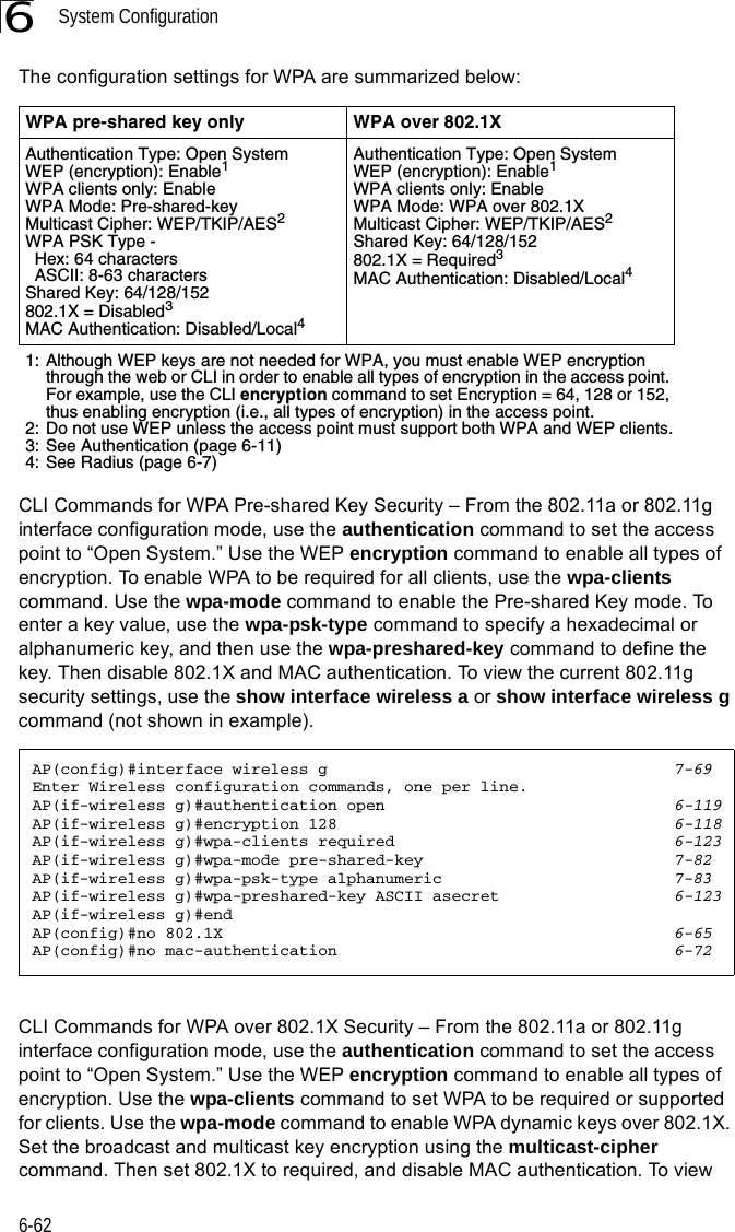
![Advanced Configuration6-376Forward Delay – The maximum time (in seconds) this device waits before changing states (i.e., discarding to learning to forwarding). This delay is required because every device must receive information about topology changes before it starts to forward frames. In addition, each port needs time to listen for conflicting information that would make it return to a discarding state; otherwise, temporary data loops might result. (Range: 4-30 seconds)• Default: 15• Minimum: The higher of 4 or [(Max. Message Age / 2) + 1]• Maximum: 30Hello Time – Interval (in seconds) at which the root device transmits a configuration message. (Range: 1-10 seconds)• Default: 2•Minimum: 1• Maximum: The lower of 10 or [(Max. Message Age / 2) -1]Maximum Age – The maximum time (in seconds) a device can wait without receiving a configuration message before attempting to reconfigure. All device ports (except for designated ports) should receive configuration messages at regular intervals. Any port that ages out STP information (provided in the last configuration message) becomes the designated port for the attached LAN. If it is a root port, a new root port is selected from among the device ports attached to the network. (Range: 6-40 seconds)• Default: 20• Minimum: The higher of 6 or [2 x (Hello Time + 1)].• Maximum: The lower of 40 or [2 x (Forward Delay - 1)]Bridge Priority – Used in selecting the root device, root port, and designated port. The device with the highest priority becomes the STP root device. However, if all devices have the same priority, the device with the lowest MAC address will then become the root device. (Note that lower numeric values indicate higher priority.)• Range: 0-65535• Default: 32768Port Cost – This parameter is used by the STP to determine the best path between devices. Therefore, lower values should be assigned to ports attached to faster media, and higher values assigned to ports with slower media. (Path cost takes precedence over port priority.) • Range: 1-65535• Default: Ethernet interface: 19; Wireless interface: 40](https://usermanual.wiki/Hewlett-Packard-Enterprise/WL575.Users-Manual-1/User-Guide-670063-Page-89.png)


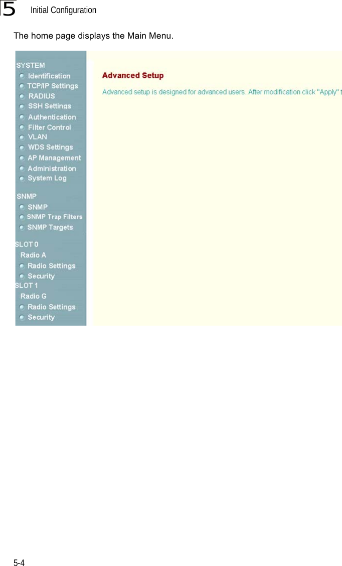
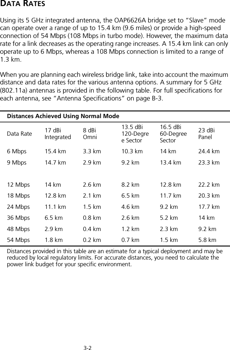
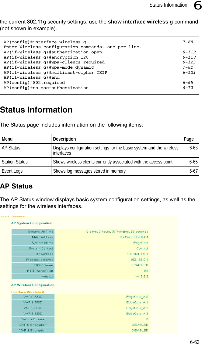
![Entering Commands7-57Exec CommandsWhen you open a new console session on an bridge, the system enters Exec command mode. Only a limited number of the commands are available in this mode. You can access all other commands only from the configuration mode. To access Exec mode, open a new console session with the user name “admin.” The command prompt displays as “Enterprise AP#” for Exec mode. Configuration CommandsConfiguration commands are used to modify bridge settings. These commands modify the running configuration and are saved in memory. The configuration commands are organized into four different modes:• Global Configuration (GC) - These commands modify the system level configuration, and include commands such as username and password. • Interface-Ethernet Configuration (IC-E) - These commands modify the Ethernet port configuration, and include command such as dns and ip.• Interface-Wireless Configuration (IC-W) - These commands modify the wireless port configuration of global parameters for the radio, and include commands such as channel and transmit-power.• Interface-Wireless Virtual bridge Configuration (IC-W-VAP) - These commands modify the wireless port configuration for each VAP, and include commands such as ssid and authentication.To enter the Global Configuration mode, enter the command configure in Exec mode. The system prompt will change to “Enterprise AP(config)#” which gives you access privilege to all Global Configuration commands.To enter Interface mode, you must enter the “interface ethernet,” or “interface wireless a,” or “interface wireless g” command while in Global Configuration mode. The system prompt will change to “Enterprise AP(if-ethernet)#,” or Enterprise AP(if-wireless)” indicating that you have access privileges to the associated commands. You can use the end command to return to the Exec mode.Username: adminPassword: [system login password]Enterprise AP#Enterprise AP#configureEnterprise AP(config)#Enterprise AP(config)#interface ethernetEnterprise AP(if-ethernet)#](https://usermanual.wiki/Hewlett-Packard-Enterprise/WL575.Users-Manual-1/User-Guide-670063-Page-125.png)


![System Management Commands7-197Example ip https serverUse this command to enable the secure hypertext transfer protocol (HTTPS) over the Secure Socket Layer (SSL), providing secure access (i.e., an encrypted connection) to the bridge’s Web interface. Use the no form to disable this function.Syntax ip https serverno ip https serverDefault Setting EnabledCommand Mode Global ConfigurationCommand Usage • Both HTTP and HTTPS service can be enabled independently.• If you enable HTTPS, you must indicate this in the URL: https://device:port_number]• When you start HTTPS, the connection is established in this way:- The client authenticates the server using the server’s digital certificate.- The client and server negotiate a set of security protocols to use for the connection.- The client and server generate session keys for encrypting and decrypting data.• The client and server establish a secure encrypted connection.A padlock icon should appear in the status bar for Internet Explorer 5.x.Example Enterprise AP(config)#ip https port 1234Enterprise AP(config)#Enterprise AP(config)#ip https serverEnterprise AP(config)#](https://usermanual.wiki/Hewlett-Packard-Enterprise/WL575.Users-Manual-1/User-Guide-670063-Page-139.png)
![Command Line Interface7-207web-redirectUse this command to enable web-based authentication of clients. Use the no form to disable this function.Syntax [no] web-redirectDefault Setting DisabledCommand Mode Global ConfigurationCommand Usage • The web redirect feature is used to support billing for a public access wireless network. After successful association to an bridge, a client is “redirected” to an bridge login web page as soon as Internet access is attempted. The client is then authenticated by entering a user name and password on the web page. This process allows controlled access for clients without requiring 802.1X or MAC authentication.• Web redirect requires a RADIUS server on the wired network with configured user names and passwords for authentication. The RADIUS server details must also be configured on the bridge. (See “show bootfile” on page 7-58.)• Use the show system command to display the current web redirect status.Example Enterprise AP(config)#web-redirectEnterprise AP(config)#](https://usermanual.wiki/Hewlett-Packard-Enterprise/WL575.Users-Manual-1/User-Guide-670063-Page-140.png)

![Command Line Interface7-227APmgmtUIThis command enables and disables management access to the bridge through SNMP, Telnet and web interfaces.Caution: Secure Web (HTTPS) connections are not affected by the UI Management or IP Management settings.SyntaxAPmgmtUI <[SNMP | Telnet | Web] enable | disable>•SNMP - Specifies SNMP management access.•Telnet - Specifies Telnet management access.•Web - Specifies web based management access.-enable/disable - Enables or disables the selected management access method.Default SettingAll enabledCommand ModeGlobal ConfigurationExampleThis example restricts management access to the indicated addresses.show apmanagementThis command shows the AP management configuration, including the IP addresses of management stations allowed to access the bridge, as well as the interface protocols which are open to management access.Command Mode ExecExampleEnterprise AP(config)#apmgmtui SNMP enableEnterprise AP(config)#Enterprise AP#show apmanagementManagement AP Information=================================AP Management IP Mode: Any IPTelnet UI: EnableWEB UI : EnableSNMP UI : Enable==================================Enterprise AP#](https://usermanual.wiki/Hewlett-Packard-Enterprise/WL575.Users-Manual-1/User-Guide-670063-Page-142.png)

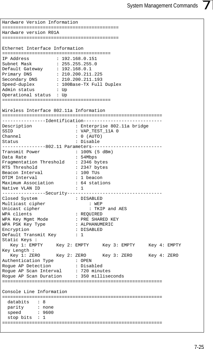
![System Management Commands7-277 dot11InterfaceAGFail Enabled dot11InterfaceBFail Enabled dot11StationAssociation Enabled dot11StationAuthentication Enabled dot11StationReAssociation Enabled dot11StationRequestFail Enabled dot1xAuthFail Enabled dot1xAuthNotInitiated Enabled dot1xAuthSuccess Enabled dot1xMacAddrAuthFail Enabled dot1xMacAddrAuthSuccess Enabled iappContextDataSent Enabled iappStationRoamedFrom Enabled iappStationRoamedTo Enabled localMacAddrAuthFail Enabled localMacAddrAuthSuccess Enabled pppLogonFail Enabled sntpServerFail Enabled configFileVersionChanged Enabled radiusServerChanged Enabled systemDown Enabled systemUp Enabled=============================================SNTP Information===========================================================Service State : DisabledSNTP (server 1) IP : 137.92.140.80SNTP (server 2) IP : 192.43.244.18Current Time : 00 : 14, Jan 1st, 1970Time Zone : -5 (BOGOTA, EASTERN, INDIANA)Daylight Saving : Disabled===========================================================Station Table Information===========================================================if-wireless A VAP [0] : 802.11a Channel : AutoNo 802.11a Channel Stations....if-wireless G VAP [0] : 802.11g Channel : AutoNo 802.11g Channel Stations....System Information==============================================================Serial Number : System Up time : 0 days, 0 hours, 16 minutes, 51 secondsSystem Name : Enterprise Wireless APSystem Location : System Contact : DavidSystem Country Code : 99 - NO_COUNTRY_SET MAC Address : 00-12-CF-05-B7-84IP Address : 192.168.0.151Subnet Mask : 255.255.255.0Default Gateway : 192.168.0.1VLAN State : DISABLEDManagement VLAN ID(AP): 1IAPP State : ENABLEDDHCP Client : ENABLEDHTTP Server : ENABLEDHTTP Server Port : 80HTTPS Server : ENABLEDHTTPS Server Port : 443Slot Status : Dual band(a/g)Boot Rom Version : v1.1.8Software Version : v4.3.2.8b03](https://usermanual.wiki/Hewlett-Packard-Enterprise/WL575.Users-Manual-1/User-Guide-670063-Page-147.png)

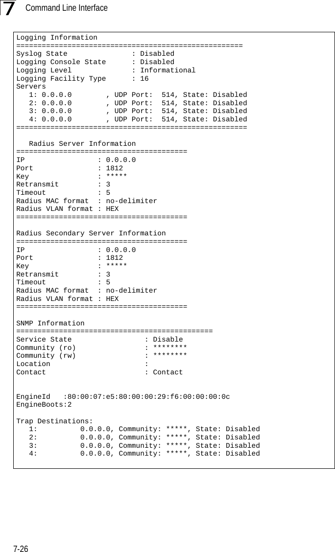
![System Logging Commands7-297logging onThis command controls logging of error messages; i.e., sending debug or error messages to memory. The no form disables the logging process.Syntax[no] logging onDefault SettingDisabledCommand Mode Global ConfigurationCommand Usage The logging process controls error messages saved to memory. You can use the logging level command to control the type of error messages that are stored in memory. Example logging hostThis command specifies syslog servers host that will receive logging messages. Use the no form to remove syslog server host.Syntaxlogging host <1 | 2 | 3 | 4> <host_name | host_ip_address> [udp_port]no logging host <1 | 2 | 3 | 4>•1 - First syslog server.•2 - Second syslog server.•3 - Third syslog server.•4 - Fourth syslog server.•host_name - The name of a syslog server. (Range: 1-20 characters)•host_ip_address - The IP address of a syslog server.•udp_port - The UDP port used by the syslog server.Default Setting NoneCommand Mode Global ConfigurationEnterprise AP(config)#logging onEnterprise AP(config)#](https://usermanual.wiki/Hewlett-Packard-Enterprise/WL575.Users-Manual-1/User-Guide-670063-Page-149.png)
Users Manual1


![Initial Configuration5-25Note: When using HyperTerminal with Microsoft® Windows® 2000, make sure that you have Windows 2000 Service Pack 2 or later installed. Windows 2000 Service Pack 2 fixes the problem of arrow keys not functioning in HyperTerminal’s VT100 emulation. See www.microsoft.com for information on Windows 2000 service packs. 4. Once you have set up the terminal correctly, press the [Enter] key to initiate the console connection. The console login screen will be displayed.For a description of how to use the CLI, see “Using the Command Line Interface” on page 7-1. For a list of all the CLI commands and detailed information on using the CLI, refer to “Command Groups” on page 7-6.Initial Configuration StepsLogging In – Enter “admin” for the user name and leave the password blank. The CLI prompt appears displaying the bridge’s name.Setting the IP Address – By default, the bridge is configured to obtain IP address settings from a DHCP server. If a DHCP server is not available, the IP address defaults to 192.168.2.2, which may not be compatible with your network. You will therefore have to use the command line interface (CLI) to assign an IP address that is compatible with your network. Type “configure” to enter configuration mode, then type “interface ethernet” to access the Ethernet interface-configuration mode.First type “no ip dhcp” to disable DHCP client mode. Then type “ip address ip-address netmask gateway,” where “ip-address” is the bridge’s IP address, “netmask” is the network mask for the network, and “gateway” is the default gateway router. Check with your system administrator to obtain an IP address that is compatible with your network.Username: adminPassword: Enterprise AP#Enterprise AP#configureEnterprise AP(config)#interface ethernetEnterprise AP(config-if)#Enterprise AP(if-ethernet)#no ip dhcpEnterprise AP(if-ethernet)#ip address 192.168.2.2 255.255.255.0 192.168.2.254Enterprise AP(if-ethernet)#](https://usermanual.wiki/Hewlett-Packard-Enterprise/WL575.Users-Manual1/User-Guide-670083-Page-50.png)


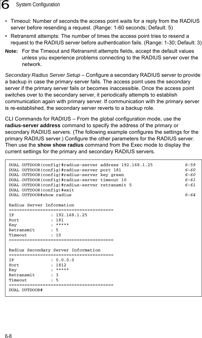


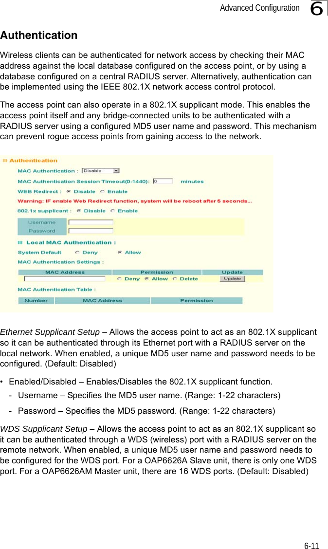


![System Configuration6-266CLI Commands for Downloading Software from a TFTP Server – Use the copy tftp file command from the Exec mode and then specify the file type, name, and IP address of the TFTP server. When the download is complete, the dir command can be used to check that the new file is present in the wireless bridge file system. To run the new software, use the reset board command to reboot the wireless bridge.DUAL OUTDOOR#copy tftp file 6-561. Application image2. Config file3. Boot block imageSelect the type of download<1,2,3>: [1]:1TFTP Source file name:bridge-img.binTFTP Server IP:192.168.1.19DUAL OUTDOOR#dir 6-58File Name Type File Size-------------------------- ---- -----------dflt-img.bin 2 1319939bridge-img.bin 2 1629577syscfg 5 17776syscfg_bak 5 17776 262144 byte(s) availableDUAL OUTDOOR#reset board 6-10Reboot system now? <y/n>: y](https://usermanual.wiki/Hewlett-Packard-Enterprise/WL575.Users-Manual1/User-Guide-670083-Page-78.png)


![Advanced Configuration6-376Forward Delay – The maximum time (in seconds) this device waits before changing states (i.e., discarding to learning to forwarding). This delay is required because every device must receive information about topology changes before it starts to forward frames. In addition, each port needs time to listen for conflicting information that would make it return to a discarding state; otherwise, temporary data loops might result. (Range: 4-30 seconds)• Default: 15• Minimum: The higher of 4 or [(Max. Message Age / 2) + 1]• Maximum: 30Hello Time – Interval (in seconds) at which the root device transmits a configuration message. (Range: 1-10 seconds)• Default: 2•Minimum: 1• Maximum: The lower of 10 or [(Max. Message Age / 2) -1]Maximum Age – The maximum time (in seconds) a device can wait without receiving a configuration message before attempting to reconfigure. All device ports (except for designated ports) should receive configuration messages at regular intervals. Any port that ages out STP information (provided in the last configuration message) becomes the designated port for the attached LAN. If it is a root port, a new root port is selected from among the device ports attached to the network. (Range: 6-40 seconds)• Default: 20• Minimum: The higher of 6 or [2 x (Hello Time + 1)].• Maximum: The lower of 40 or [2 x (Forward Delay - 1)]Bridge Priority – Used in selecting the root device, root port, and designated port. The device with the highest priority becomes the STP root device. However, if all devices have the same priority, the device with the lowest MAC address will then become the root device. (Note that lower numeric values indicate higher priority.)• Range: 0-65535• Default: 32768Port Cost – This parameter is used by the STP to determine the best path between devices. Therefore, lower values should be assigned to ports attached to faster media, and higher values assigned to ports with slower media. (Path cost takes precedence over port priority.) • Range: 1-65535• Default: Ethernet interface: 19; Wireless interface: 40](https://usermanual.wiki/Hewlett-Packard-Enterprise/WL575.Users-Manual1/User-Guide-670083-Page-89.png)


![Entering Commands7-57Exec CommandsWhen you open a new console session on an bridge, the system enters Exec command mode. Only a limited number of the commands are available in this mode. You can access all other commands only from the configuration mode. To access Exec mode, open a new console session with the user name “admin.” The command prompt displays as “Enterprise AP#” for Exec mode. Configuration CommandsConfiguration commands are used to modify bridge settings. These commands modify the running configuration and are saved in memory. The configuration commands are organized into four different modes:• Global Configuration (GC) - These commands modify the system level configuration, and include commands such as username and password. • Interface-Ethernet Configuration (IC-E) - These commands modify the Ethernet port configuration, and include command such as dns and ip.• Interface-Wireless Configuration (IC-W) - These commands modify the wireless port configuration of global parameters for the radio, and include commands such as channel and transmit-power.• Interface-Wireless Virtual bridge Configuration (IC-W-VAP) - These commands modify the wireless port configuration for each VAP, and include commands such as ssid and authentication.To enter the Global Configuration mode, enter the command configure in Exec mode. The system prompt will change to “Enterprise AP(config)#” which gives you access privilege to all Global Configuration commands.To enter Interface mode, you must enter the “interface ethernet,” or “interface wireless a,” or “interface wireless g” command while in Global Configuration mode. The system prompt will change to “Enterprise AP(if-ethernet)#,” or Enterprise AP(if-wireless)” indicating that you have access privileges to the associated commands. You can use the end command to return to the Exec mode.Username: adminPassword: [system login password]Enterprise AP#Enterprise AP#configureEnterprise AP(config)#Enterprise AP(config)#interface ethernetEnterprise AP(if-ethernet)#](https://usermanual.wiki/Hewlett-Packard-Enterprise/WL575.Users-Manual1/User-Guide-670083-Page-125.png)


![System Management Commands7-197Example ip https serverUse this command to enable the secure hypertext transfer protocol (HTTPS) over the Secure Socket Layer (SSL), providing secure access (i.e., an encrypted connection) to the bridge’s Web interface. Use the no form to disable this function.Syntax ip https serverno ip https serverDefault Setting EnabledCommand Mode Global ConfigurationCommand Usage • Both HTTP and HTTPS service can be enabled independently.• If you enable HTTPS, you must indicate this in the URL: https://device:port_number]• When you start HTTPS, the connection is established in this way:- The client authenticates the server using the server’s digital certificate.- The client and server negotiate a set of security protocols to use for the connection.- The client and server generate session keys for encrypting and decrypting data.• The client and server establish a secure encrypted connection.A padlock icon should appear in the status bar for Internet Explorer 5.x.Example Enterprise AP(config)#ip https port 1234Enterprise AP(config)#Enterprise AP(config)#ip https serverEnterprise AP(config)#](https://usermanual.wiki/Hewlett-Packard-Enterprise/WL575.Users-Manual1/User-Guide-670083-Page-139.png)
![Command Line Interface7-207web-redirectUse this command to enable web-based authentication of clients. Use the no form to disable this function.Syntax [no] web-redirectDefault Setting DisabledCommand Mode Global ConfigurationCommand Usage • The web redirect feature is used to support billing for a public access wireless network. After successful association to an bridge, a client is “redirected” to an bridge login web page as soon as Internet access is attempted. The client is then authenticated by entering a user name and password on the web page. This process allows controlled access for clients without requiring 802.1X or MAC authentication.• Web redirect requires a RADIUS server on the wired network with configured user names and passwords for authentication. The RADIUS server details must also be configured on the bridge. (See “show bootfile” on page 7-58.)• Use the show system command to display the current web redirect status.Example Enterprise AP(config)#web-redirectEnterprise AP(config)#](https://usermanual.wiki/Hewlett-Packard-Enterprise/WL575.Users-Manual1/User-Guide-670083-Page-140.png)
![Command Line Interface7-227APmgmtUIThis command enables and disables management access to the bridge through SNMP, Telnet and web interfaces.Caution: Secure Web (HTTPS) connections are not affected by the UI Management or IP Management settings.SyntaxAPmgmtUI <[SNMP | Telnet | Web] enable | disable>•SNMP - Specifies SNMP management access.•Telnet - Specifies Telnet management access.•Web - Specifies web based management access.-enable/disable - Enables or disables the selected management access method.Default SettingAll enabledCommand ModeGlobal ConfigurationExampleThis example restricts management access to the indicated addresses.show apmanagementThis command shows the AP management configuration, including the IP addresses of management stations allowed to access the bridge, as well as the interface protocols which are open to management access.Command Mode ExecExampleEnterprise AP(config)#apmgmtui SNMP enableEnterprise AP(config)#Enterprise AP#show apmanagementManagement AP Information=================================AP Management IP Mode: Any IPTelnet UI: EnableWEB UI : EnableSNMP UI : Enable==================================Enterprise AP#](https://usermanual.wiki/Hewlett-Packard-Enterprise/WL575.Users-Manual1/User-Guide-670083-Page-142.png)


![System Management Commands7-277 dot11InterfaceAGFail Enabled dot11InterfaceBFail Enabled dot11StationAssociation Enabled dot11StationAuthentication Enabled dot11StationReAssociation Enabled dot11StationRequestFail Enabled dot1xAuthFail Enabled dot1xAuthNotInitiated Enabled dot1xAuthSuccess Enabled dot1xMacAddrAuthFail Enabled dot1xMacAddrAuthSuccess Enabled iappContextDataSent Enabled iappStationRoamedFrom Enabled iappStationRoamedTo Enabled localMacAddrAuthFail Enabled localMacAddrAuthSuccess Enabled pppLogonFail Enabled sntpServerFail Enabled configFileVersionChanged Enabled radiusServerChanged Enabled systemDown Enabled systemUp Enabled=============================================SNTP Information===========================================================Service State : DisabledSNTP (server 1) IP : 137.92.140.80SNTP (server 2) IP : 192.43.244.18Current Time : 00 : 14, Jan 1st, 1970Time Zone : -5 (BOGOTA, EASTERN, INDIANA)Daylight Saving : Disabled===========================================================Station Table Information===========================================================if-wireless A VAP [0] : 802.11a Channel : AutoNo 802.11a Channel Stations....if-wireless G VAP [0] : 802.11g Channel : AutoNo 802.11g Channel Stations....System Information==============================================================Serial Number : System Up time : 0 days, 0 hours, 16 minutes, 51 secondsSystem Name : Enterprise Wireless APSystem Location : System Contact : DavidSystem Country Code : 99 - NO_COUNTRY_SET MAC Address : 00-12-CF-05-B7-84IP Address : 192.168.0.151Subnet Mask : 255.255.255.0Default Gateway : 192.168.0.1VLAN State : DISABLEDManagement VLAN ID(AP): 1IAPP State : ENABLEDDHCP Client : ENABLEDHTTP Server : ENABLEDHTTP Server Port : 80HTTPS Server : ENABLEDHTTPS Server Port : 443Slot Status : Dual band(a/g)Boot Rom Version : v1.1.8Software Version : v4.3.2.8b03](https://usermanual.wiki/Hewlett-Packard-Enterprise/WL575.Users-Manual1/User-Guide-670083-Page-147.png)
![System Logging Commands7-297logging onThis command controls logging of error messages; i.e., sending debug or error messages to memory. The no form disables the logging process.Syntax[no] logging onDefault SettingDisabledCommand Mode Global ConfigurationCommand Usage The logging process controls error messages saved to memory. You can use the logging level command to control the type of error messages that are stored in memory. Example logging hostThis command specifies syslog servers host that will receive logging messages. Use the no form to remove syslog server host.Syntaxlogging host <1 | 2 | 3 | 4> <host_name | host_ip_address> [udp_port]no logging host <1 | 2 | 3 | 4>•1 - First syslog server.•2 - Second syslog server.•3 - Third syslog server.•4 - Fourth syslog server.•host_name - The name of a syslog server. (Range: 1-20 characters)•host_ip_address - The IP address of a syslog server.•udp_port - The UDP port used by the syslog server.Default Setting NoneCommand Mode Global ConfigurationEnterprise AP(config)#logging onEnterprise AP(config)#](https://usermanual.wiki/Hewlett-Packard-Enterprise/WL575.Users-Manual1/User-Guide-670083-Page-149.png)
