Hewlett Packard Enterprise WL575 Outdoor 11a Building to Building Bridge & 11bg AP User Manual OAP6626A UG 32
Hewlett-Packard Company Outdoor 11a Building to Building Bridge & 11bg AP OAP6626A UG 32
Contents
- 1. Users Manual 1
- 2. Users Manual 2
- 3. Users Manual1
- 4. Users Manual2
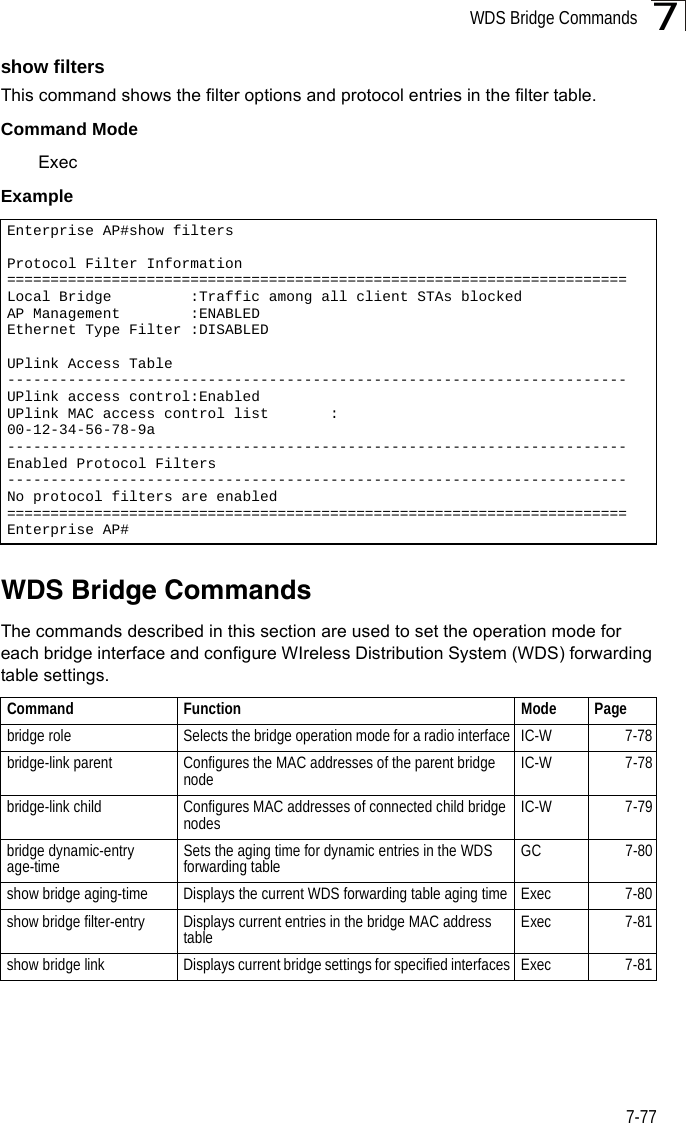
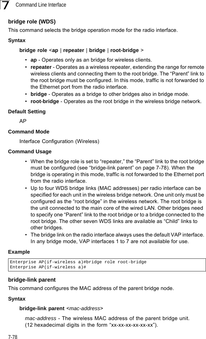
Users Manual 2


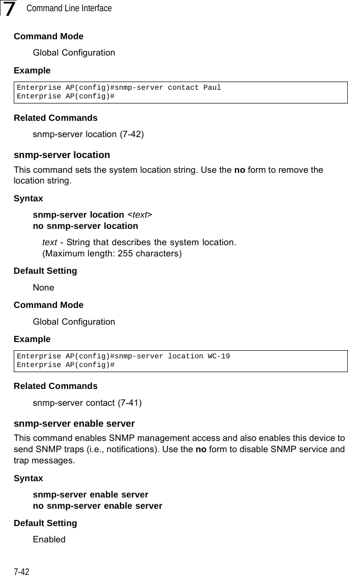
![Command Line Interface7-387DHCP Relay CommandsDynamic Host Configuration Protocol (DHCP) can dynamically allocate an IP address and other configuration information to network clients that broadcast a request. To receive the broadcast request, the DHCP server would normally have to be on the same subnet as the client. However, when the bridge’s DHCP relay agent is enabled, received client requests can be forwarded directly by the bridge to a known DHCP server on another subnet. Responses from the DHCP server are returned to the bridge, which then broadcasts them back to clients.dhcp-relay enableThis command enables the bridge’s DHCP relay agent. Use the no form to disable the agent.Syntax[no] dhcp-relay enableDefault Setting DisabledCommand Mode Global ConfigurationCommand Usage • For the DHCP relay agent to function, the primary DHCP server must be configured using the dhcp-relay primary command. A secondary DHCP server does not need to be configured, but it is recommended.• If there is no response from the primary DHCP server, and a secondary server has been configured, the agent will then attempt to send DHCP requests to the secondary server.Example Table 7-8. DHCP Relay CommandsCommand Function Mode Pagedhcp-relay enable Enables the DHCP relay agent GC 7-38dhcp-relay Sets the primary and secondary DHCP server address GC 7-39show dhcp-relay Shows current DHCP relay configuration settings Exec 7-39Enterprise AP(config)#dhcp-relay enableEnterprise AP(config)#](https://usermanual.wiki/Hewlett-Packard-Enterprise/WL575.Users-Manual-2/User-Guide-670064-Page-8.png)
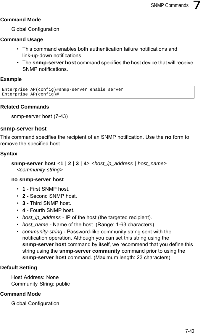
![SNMP Commands7-417snmp-server communityThis command defines the community access string for the Simple Network Management Protocol. Use the no form to remove the specified community string.Syntaxsnmp-server community string [ro | rw]no snmp-server community string•string - Community string that acts like a password and permits access to the SNMP protocol. (Maximum length: 23 characters, case sensitive)•ro - Specifies read-only access. Authorized management stations are only able to retrieve MIB objects. •rw - Specifies read/write access. Authorized management stations are able to both retrieve and modify MIB objects.Default Setting • public - Read-only access. Authorized management stations are only able to retrieve MIB objects.• private - Read/write access. Authorized management stations are able to both retrieve and modify MIB objects.Command Mode Global ConfigurationCommand Usage If you enter a community string without the ro or rw option, the default is read only.Example snmp-server contactThis command sets the system contact string. Use the no form to remove the system contact information.Syntaxsnmp-server contact stringno snmp-server contactstring - String that describes the system contact. (Maximum length: 255 characters)Default Setting NoneEnterprise AP(config)#snmp-server community alpha rwEnterprise AP(config)#](https://usermanual.wiki/Hewlett-Packard-Enterprise/WL575.Users-Manual-2/User-Guide-670064-Page-11.png)


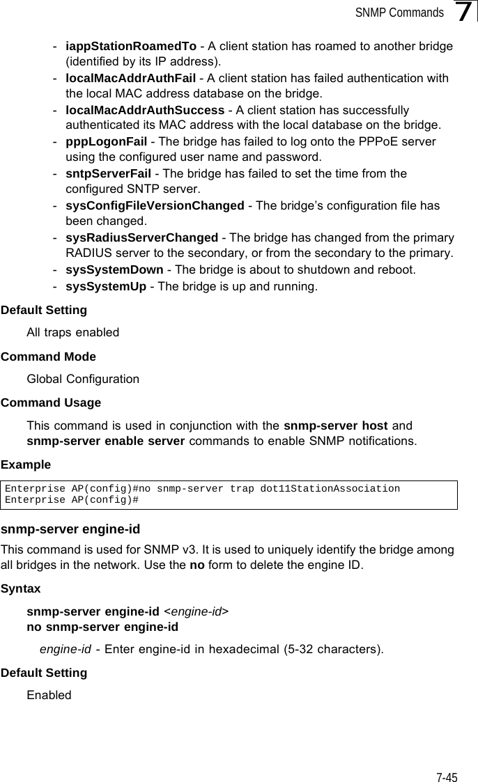
![Command Line Interface7-487snmp-server targetsThis command configures SNMP v3 notification targets. Use the no form to delete an SNMP v3 target.Syntaxsnmp-server targets <target-id> <ip-addr> <sec-name> [version {3}] [udp-port {port-number}] [notification-type {TRAP}]no snmp-server targets <target-id>•target-id - A user-defined name that identifies a receiver of SNMP notifications. (Maximum length: 32 characters)•ip-addr - Specifies the IP address of the management station to receive notifications.•sec-name - The defined SNMP v3 user name that is to receive notifications.•version - The SNMP version of notifications. Currently only version 3 is supported in this command.•udp-port - The UDP port that is used on the receiving management station for notifications.•notification-type - The type of notification that is sent. Currently only TRAP is supported.Default Setting NoneCommand Mode Global ConfigurationCommand Usage • The bridge supports up to 10 SNMP v3 target IDs.• The SNMP v3 user name that is specified in the target must first be configured using the snmp-server user command.Example Enterprise AP(config)#snmp-server targets mytraps 192.168.1.33 chrisEnterprise AP(config)#](https://usermanual.wiki/Hewlett-Packard-Enterprise/WL575.Users-Manual-2/User-Guide-670064-Page-18.png)
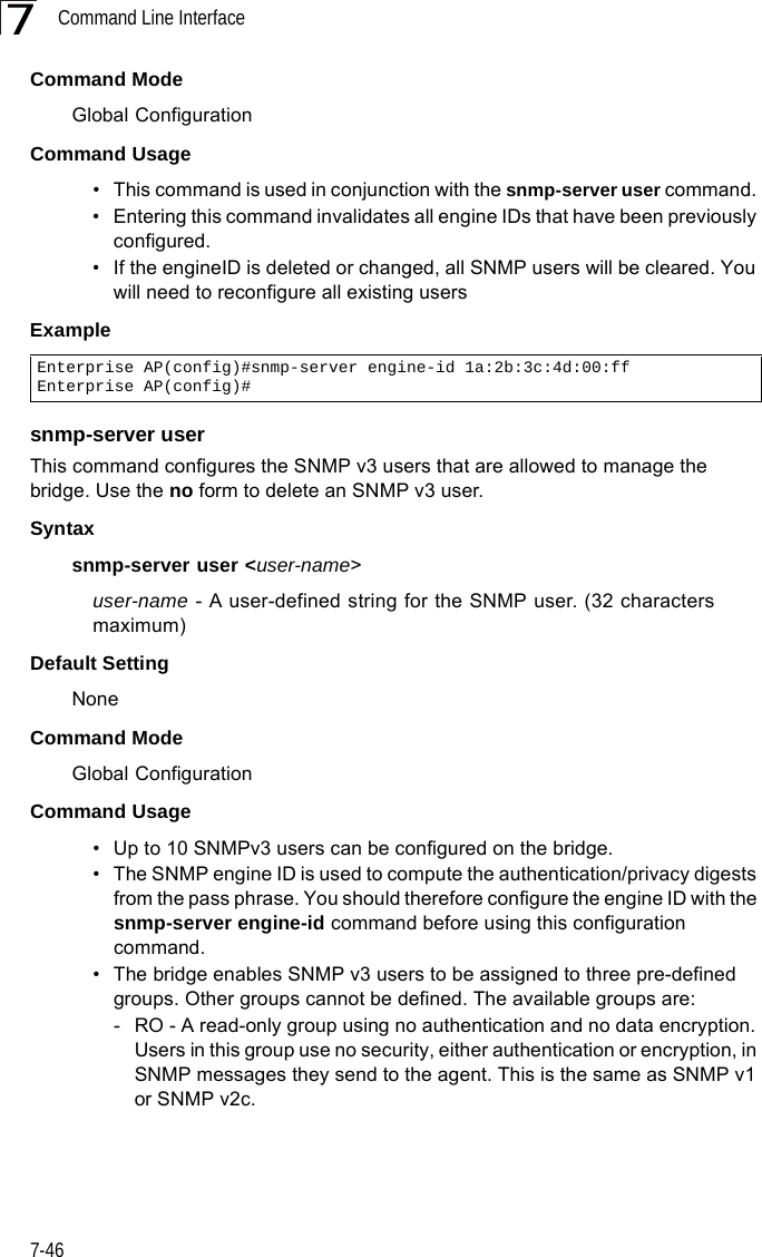
![SNMP Commands7-497snmp-server filterThis command configures SNMP v3 notification filters. Use the no form to delete an SNMP v3 filter or remove a subtree from a filter.Syntaxsnmp-server filter <filter-id> <include | exclude> <subtree> [mask {mask}]no snmp-server filter <filter-id> [subtree]•filter-id - A user-defined name that identifies an SNMP v3 notification filter. (Maximum length: 32 characters)•include - Defines a filter type that includes objects in the MIB subtree.•exclude - Defines a filter type that excludes objects in the MIB subtree.•subtree - The part of the MIB subtree that is to be filtered.•mask - An optional hexadecimal value bit mask to define objects in the MIB subtree. Default Setting NoneCommand Mode Global ConfigurationCommand Usage • The bridge allows up to 10 notification filters to be created. Each filter can be defined by up to 20 MIB subtree ID entries.• Use the command more than once with the same filter ID to build a filter that includes or excludes multiple MIB objects. Note that the filter entries are applied in the sequence that they are defined.• The MIB subtree must be defined in the form “.1.3.6.1” and always start with a “.”.• The mask is a hexadecimal value with each bit masking the corresponding ID in the MIB subtree. A “1” in the mask indicates an exact match and a “0” indicates a “wild card.” For example, a mask value of 0xFFBF provides a bit mask “1111 1111 1011 1111.” If applied to the subtree 1.3.6.1.2.1.2.2.1.1.23, the zero corresponds to the 10th subtree ID. When there are more subtree IDs than bits in the mask, the mask is padded with ones.Example Enterprise AP(config)#snmp-server filter trapfilter include .1Enterprise AP(config)#snmp-server filter trapfilter exclude .1.3.6.1.2.1.2.2.1.1.23](https://usermanual.wiki/Hewlett-Packard-Enterprise/WL575.Users-Manual-2/User-Guide-670064-Page-19.png)


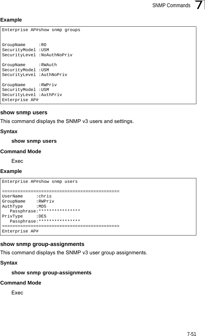
![Command Line Interface7-527Example show snmp targetThis command displays the SNMP v3 notification target settings.Syntaxshow snmp targetCommand Mode ExecExample show snmp filterThis command displays the SNMP v3 notification filter settings.Syntaxshow snmp filter [filter-id] •filter-id - A user-defined name that identifies an SNMP v3 notification filter. (Maximum length: 32 characters)Command Mode ExecExample Enterprise AP#show snmp group-assignmentsGroupName :RWPrivUserName :chrisEnterprise AP#Enterprise AP#Enterprise AP#show snmp targetHost ID : mytrapsUser : chrisIP Address : 192.168.1.33UDP Port : 162=============================Enterprise AP#Enterprise AP#show snmp filterFilter: trapfilter Type: include Subtree: iso.3.6.1.2.1.2.2.1 Type: exclude Subtree: iso.3.6.1.2.1.2.2.1.1.23=============================Enterprise AP#](https://usermanual.wiki/Hewlett-Packard-Enterprise/WL575.Users-Manual-2/User-Guide-670064-Page-22.png)

![Flash/File Commands7-577The following example shows how to download a configuration file: deleteThis command deletes a file or image.Syntaxdelete <filename>filename - Name of the configuration file or image name.Default Setting NoneCommand Mode ExecCaution: Beware of deleting application images from flash memory. At least one application image is required in order to boot the bridge. If there are multiple image files in flash memory, and the one used to boot the bridge is deleted, be sure you first use the bootfile command to update the application image file booted at startup before you reboot the bridge.Example This example shows how to delete the test.cfg configuration file from flash memory.Related Commandsbootfile (7-55)dir (7-58)Enterprise AP#copy tftp file1. Application image2. Config file3. Boot block imageSelect the type of download<1,2,3>: [1]:2TFTP Source file name:syscfgTFTP Server IP:192.168.1.19Enterprise AP#Enterprise AP#delete test.cfgAre you sure you wish to delete this file? <y/n>:Enterprise AP#](https://usermanual.wiki/Hewlett-Packard-Enterprise/WL575.Users-Manual-2/User-Guide-670064-Page-27.png)

![RADIUS Client7-597RADIUS ClientRemote Authentication Dial-in User Service (RADIUS) is a logon authentication protocol that uses software running on a central server to control access for RADIUS-aware devices to the network. An authentication server contains a database of credentials, such as users names and passwords, for each wireless client that requires access to the bridge.radius-server addressThis command specifies the primary and secondary RADIUS servers. Syntaxradius-server [secondary] address <host_ip_address | host_name>•secondary - Secondary server.•host_ip_address - IP address of server.•host_name - Host name of server. (Range: 1-20 characters)Default Setting NoneTable 7-11. RADIUS ClientCommand Function Mode Pageradius-server address Specifies the RADIUS server GC 7-59radius-server port Sets the RADIUS server network port GC 7-60radius-server key Sets the RADIUS encryption key GC 7-60radius-server retransmit Sets the number of retries GC 7-61radius-server timeout Sets the interval between sending authentication requests GC 7-61radius-server port-accounting Sets the RADIUS Accounting server network port GC 7-62radius-server timeout-interim Sets the interval between transmitting accounting updates to the RADIUS server GC 7-62radius-server radius-mac-format Sets the format for specifying MAC addresses on the RADIUS server GC 7-63radius-server vlan-format Sets the format for specifying VLAN IDs on the RADIUS server GC 7-63show radius Shows the current RADIUS settings Exec 7-64](https://usermanual.wiki/Hewlett-Packard-Enterprise/WL575.Users-Manual-2/User-Guide-670064-Page-29.png)
![Command Line Interface7-607Command Mode Global ConfigurationExample radius-server portThis command sets the RADIUS server network port. Syntaxradius-server [secondary] port <port_number>•secondary - Secondary server.•port_number - RADIUS server UDP port used for authentication messages. (Range: 1024-65535)Default Setting 1812Command Mode Global ConfigurationExample radius-server keyThis command sets the RADIUS encryption key. Syntax radius-server [secondary] key <key_string>•secondary - Secondary server.•key_string - Encryption key used to authenticate logon access for client. Do not use blank spaces in the string. (Maximum length: 20 characters)Default Setting DEFAULTCommand Mode Global ConfigurationExample Enterprise AP(config)#radius-server address 192.168.1.25Enterprise AP(config)#Enterprise AP(config)#radius-server port 181Enterprise AP(config)#Enterprise AP(config)#radius-server key greenEnterprise AP(config)#](https://usermanual.wiki/Hewlett-Packard-Enterprise/WL575.Users-Manual-2/User-Guide-670064-Page-30.png)
![RADIUS Client7-617radius-server retransmitThis command sets the number of retries. Syntaxradius-server [secondary] retransmit number_of_retries•secondary - Secondary server.•number_of_retries - Number of times the bridge will try to authenticate logon access via the RADIUS server. (Range: 1 - 30)Default Setting 3Command Mode Global ConfigurationExample radius-server timeoutThis command sets the interval between transmitting authentication requests to the RADIUS server. Syntax radius-server [secondary] timeout number_of_seconds•secondary - Secondary server.•number_of_seconds - Number of seconds the bridge waits for a reply before resending a request. (Range: 1-60)Default Setting 5Command Mode Global ConfigurationExample Enterprise AP(config)#radius-server retransmit 5Enterprise AP(config)#Enterprise AP(config)#radius-server timeout 10Enterprise AP(config)#](https://usermanual.wiki/Hewlett-Packard-Enterprise/WL575.Users-Manual-2/User-Guide-670064-Page-31.png)
![Command Line Interface7-627radius-server port-accountingThis command sets the RADIUS Accounting server network port. Syntaxradius-server [secondary] port-accounting <port_number>•secondary - Secondary server. If secondary is not specified, then the bridge assumes you are configuring the primary RADIUS server.•port_number - RADIUS Accounting server UDP port used for accounting messages. (Range: 0 or 1024-65535)Default Setting 0 (disabled)Command Mode Global ConfigurationCommand Usage • When the RADIUS Accounting server UDP port is specified, a RADIUS accounting session is automatically started for each user that is successfully authenticated to the bridge.Example radius-server timeout-interimThis command sets the interval between transmitting accounting updates to the RADIUS server.Syntax radius-server [secondary] timeout-interim <number_of_seconds>•secondary - Secondary server.•number_of_seconds - Number of seconds the bridge waits between transmitting accounting updates. (Range: 60-86400)Default Setting 3600Command Mode Global ConfigurationCommand Usage • The bridge sends periodic accounting updates after every interim period until the user logs off and a “stop” message is sent.Enterprise AP(config)#radius-server port-accounting 1813Enterprise AP(config)#](https://usermanual.wiki/Hewlett-Packard-Enterprise/WL575.Users-Manual-2/User-Guide-670064-Page-32.png)


![Command Line Interface7-727Command ModeGlobal ConfigurationExampleRelated Commands802.1x-supplicant user (7-68)mac-authentication serverThis command sets address filtering to be performed with local or remote options. Use the no form to disable MAC address authentication.Syntaxmac-authentication server [local | remote]•local - Authenticate the MAC address of wireless clients with the local authentication database during 802.11 association.•remote - Authenticate the MAC address of wireless clients with the RADIUS server during 802.1X authentication.DefaultDisabledCommand ModeGlobal ConfigurationExampleRelated Commandsaddress filter entry (7-71)radius-server address (7-59)802.1x-supplicant user (7-68)mac-authentication session-timeoutThis command sets the interval at which associated clients will be re-authenticated with the RADIUS server authentication database. Use the no form to disable reauthentication.Syntaxmac-authentication session-timeout <minutes>minutes - Re-authentication interval. (Range: 0-1440)Enterprise AP(config)#address filter delete 00-70-50-cc-99-1b Enterprise AP(config)#Enterprise AP(config)#mac-authentication server remoteEnterprise AP(config)#](https://usermanual.wiki/Hewlett-Packard-Enterprise/WL575.Users-Manual-2/User-Guide-670064-Page-42.png)

![Filtering Commands7-757filter uplink enableThis command enables filtering of MAC addresses from the Ethernet port.Syntax[no] filter uplink enableDefaultDisabledCommand ModeGlobal ConfigurationExamplefilter uplinkThis command adds or deletes MAC addresses from the uplink filtering table.Syntaxfilter uplink <add | delete> MAC addressMAC address - Specifies a MAC address in the form xx-xx-xx-xx-xx-xx. A maximum of eight addresses can be added to the filtering table.DefaultDisabledCommand ModeGlobal ConfigurationExamplefilter ethernet-type enableThis command checks the Ethernet type on all incoming and outgoing Ethernet packets against the protocol filtering table. Use the no form to disable this feature.Syntaxfilter ethernet-type enableno filter ethernet-type enableDefaultDisabledCommand ModeEnterprise AP(config)#filter uplink enableEnterprise AP(config)#Enterprise AP(config)#filter uplink add 00-12-34-56-78-9aEnterprise AP(config)#](https://usermanual.wiki/Hewlett-Packard-Enterprise/WL575.Users-Manual-2/User-Guide-670064-Page-45.png)


![WDS Bridge Commands7-817show bridge filter-entryThis command displays current entries in the WDS forwarding table.Command Mode ExecExample show bridge linkThis command displays WDS bridge link and spanning tree settings for specified interfaces.Syntaxshow bridge link <ethernet | wireless <a | g> [index]>•ethernet - Specifies the Ethernet interface.•wireless - Specifies a wireless interface.-a - The 802.11a radio interface.-g - The 802.11g radio interface.-index - The index number of a bridge link. (Range: 1 - 6)Command Mode ExecEnterprise AP#show bridge filter-entrymax entry numbers =512current entry nums =13**************************************************************************************************** Bridge MAC Addr Table ************************************************************************************************************| MAC | Port |Fwd_type| VlanID|origin life|remain Life| Type | 01 80 c2 00 00 00 0 5 4095 300 300 Static 01 80 c2 00 00 03 0 5 4095 300 300 Static 00 30 f1 f0 9b 20 1 0 1 300 300 Static 00 30 f1 f0 9b 21 1 0 1 300 300 Static 00 30 f1 f0 9b 22 1 0 1 300 300 Static 00 30 f1 f0 9b 23 1 0 1 300 300 Static 00 30 f1 f0 9b 24 1 0 1 300 300 Static 00 30 f1 f0 9b 25 1 0 1 300 300 Static 00 30 f1 f0 9b 26 1 0 1 300 300 Static 00 30 f1 f0 9b 27 1 0 1 300 300 Static 00 30 f1 2f be 30 1 3 0 300 175 Dynamic 00 30 f1 f0 9a 9c 1 0 1 300 300 Static ff ff ff ff ff ff 0 4 4095 300 300 StaticEnterprise AP#](https://usermanual.wiki/Hewlett-Packard-Enterprise/WL575.Users-Manual-2/User-Guide-670064-Page-51.png)

![Command Line Interface7-847bridge stp forwarding-delayUse this command to configure the spanning tree bridge forward time globally for the wireless bridge. Use the no form to restore the default.Syntax bridge stp forwarding-delay <seconds>no bridge stp forwarding-delayseconds - Time in seconds. (Range: 4 - 30 seconds)The minimum value is the higher of 4 or [(max-age / 2) + 1]. Default Setting 15 secondsCommand Mode Global ConfigurationCommand Usage This command sets the maximum time (in seconds) the root device will wait before changing states (i.e., discarding to learning to forwarding). This delay is required because every device must receive information about topology changes before it starts to forward frames. In addition, each port needs time to listen for conflicting information that would make it return to the discarding state; otherwise, temporary data loops might result.Example bridge stp hello-timeUse this command to configure the spanning tree bridge hello time globally for the wireless bridge. Use the no form to restore the default.Syntax bridge stp hello-time <time>no bridge stp hello-timetime - Time in seconds. (Range: 1-10 seconds). The maximum value is the lower of 10 or [(max-age / 2) -1]. Default Setting 2 secondsCommand Mode Global ConfigurationCommand Usage This command sets the time interval (in seconds) at which the root device transmits a configuration message.Enterprise AP(config)#bridge stp forwarding-delay 20Enterprise AP(config)#](https://usermanual.wiki/Hewlett-Packard-Enterprise/WL575.Users-Manual-2/User-Guide-670064-Page-54.png)
![Spanning Tree Commands7-857Example bridge stp max-ageUse this command to configure the spanning tree bridge maximum age globally for the wireless bridge. Use the no form to restore the default.Syntax bridge stp max-age <seconds>no bridge stp max-ageseconds - Time in seconds. (Range: 6-40 seconds)The minimum value is the higher of 6 or [2 x (hello-time + 1)].The maximum value is the lower of 40 or [2 x (forward-time - 1)].Default Setting 20 secondsCommand Mode Global ConfigurationCommand Usage This command sets the maximum time (in seconds) a device can wait without receiving a configuration message before attempting to reconfigure. All device ports (except for designated ports) should receive configuration messages at regular intervals. Any port that ages out STP information (provided in the last configuration message) becomes the designated port for the attached LAN. If it is a root port, a new root port is selected from among the device ports attached to the network.Example bridge stp priorityUse this command to configure the spanning tree priority globally for the wireless bridge. Use the no form to restore the default.Syntax bridge stp priority<priority>no bridge stp prioritypriority - Priority of the bridge. (Range: 0 - 65535) Default Setting 32768Enterprise AP(config)#bridge stp hello-time 5Enterprise AP(config)#Enterprise AP(config)#bridge stp max-age 40Enterprise AP(config)#](https://usermanual.wiki/Hewlett-Packard-Enterprise/WL575.Users-Manual-2/User-Guide-670064-Page-55.png)


![Command Line Interface7-927shutdown This command disables the Ethernet interface. To restart a disabled interface, use the no form.Syntax shutdownno shutdownDefault Setting Interface enabledCommand Mode Interface Configuration (Ethernet)Command Usage This command allows you to disable the Ethernet port due to abnormal behavior (e.g., excessive collisions), and reenable it after the problem has been resolved. You may also want to disable the Ethernet port for security reasons. Example The following example disables the Ethernet port.show interface ethernetThis command displays the status for the Ethernet interface.Syntaxshow interface [ethernet]Default Setting Ethernet interfaceCommand Mode ExecEnterprise AP(if-ethernet)#shutdownEnterprise AP(if-ethernet)#](https://usermanual.wiki/Hewlett-Packard-Enterprise/WL575.Users-Manual-2/User-Guide-670064-Page-62.png)

![Wireless Interface Commands7-957Default Setting NoneCommand Mode Global Configuration Example To specify the 802.11a interface, enter the following command:vapThis command provides access to the VAP (Virtual bridge) interface configuration mode.Syntaxvap <vap-id>vap-id - The number that identifies the VAP interface. (Options: 0-7)Default Setting NoneCommand Mode Interface Configuration (Wireless)ExamplespeedThis command configures the maximum data rate at which the bridge transmits unicast packets. Syntaxspeed <speed>speed - Maximum access speed allowed for wireless clients. (Options for 802.11a: 6, 9, 12, 18, 24, 36, 48, 54 Mbps) (Options for 802.11b/g: 1, 2, 5.5, 6, 9, 11, 12, 18, 24, 36, 48, 54 Mbps)Enterprise AP(config)#interface wireless aEnterprise AP(if-wireless a)#Enterprise AP(if-wireless g)#vap 0Enterprise AP(if-wireless g: VAP[0])#](https://usermanual.wiki/Hewlett-Packard-Enterprise/WL575.Users-Manual-2/User-Guide-670064-Page-65.png)


![Command Line Interface7-1007ExamplepreambleThis command sets the length of the signal preamble that is used at the start of a 802.11b/g data transmission.Syntaxpreamble [long | short-or-long]•long - Sets the preamble to long (192 microseconds).•short-or-long - Sets the preamble to short if no 802.11b clients are detected (96 microseconds).Default SettingShort-or-LongCommand ModeInterface Configuration (Wireless - 802.11b/g)Command Usage• Using a short preamble instead of a long preamble can increase data throughput on the bridge, but requires that all clients can support a short preamble.• Set the preamble to long to ensure the bridge can support all 802.11b and 802.11g clients.Exampleantenna controlThis command selects the use of two diversity antennas or a single antenna for the radio interface.Syntaxantenna control <diversity | left | right>•diversity - The radio uses both antennas in a diversity system. Select this method when the Antenna ID is set to “Default Antenna” to use the bridge's integrated antennas. The bridge does not support external diversity antennas.•left - The radio only uses the antenna on the left side (the side farthest from the bridge LEDs). The bridge does not support an external antenna connection on its left antenna. Therefore, this method is not valid for the bridge.Enterprise AP(if-wireless g)#radio-mode gEnterprise AP(if-wireless g)#Enterprise AP(if-wireless g)#preamble shortEnterprise AP(if-wireless g)#](https://usermanual.wiki/Hewlett-Packard-Enterprise/WL575.Users-Manual-2/User-Guide-670064-Page-70.png)


![Wireless Interface Commands7-1057Default Setting 2347Command Mode Interface Configuration (Wireless)Command Usage • If the threshold is set to 0, the bridge always sends RTS signals. If set to 2347, the bridge never sends RTS signals. If set to any other value, and the packet size equals or exceeds the RTS threshold, the RTS/CTS (Request to Send / Clear to Send) mechanism will be enabled.• The bridge sends RTS frames to a receiving station to negotiate the sending of a data frame. After receiving an RTS frame, the station sends a CTS frame to notify the sending station that it can start sending data. • bridges contending for the wireless medium may not be aware of each other. The RTS/CTS mechanism can solve this “Hidden Node” problem.Examplesuper-a This command enables Atheros proprietary Super A performance enhancements. Use the no form to disable this function.Syntax[no] super-a Default Setting DisabledCommand Mode Interface Configuration (Wireless - 802.11a)Command Usage Super A enhancements include bursting, compression, and fast frames. Maximum throughput ranges between 40 to 60 Mbps for connections to Atheros-compatible clients.ExampleEnterprise AP(if-wireless g)#rts-threshold 256Enterprise AP(if-wireless g)#Enterprise AP(if-wireless a)#super aEnterprise AP(if-wireless a)#](https://usermanual.wiki/Hewlett-Packard-Enterprise/WL575.Users-Manual-2/User-Guide-670064-Page-75.png)
![Command Line Interface7-1067super-g This command enables Atheros proprietary Super G performance enhancements. Use the no form to disable this function.Syntax[no] super-g Default Setting DisabledCommand Mode Interface Configuration (Wireless - 802.11g)Command Usage These enhancements include bursting, compression, fast frames and dynamic turbo. Maximum throughput ranges between 40 to 60 Mbps for connections to Atheros-compatible clients.Exampledescription This command adds a description to a the wireless interface. Use the no form to remove the description.Syntaxdescription <string>no descriptionstring - Comment or a description for this interface. (Range: 1-80 characters)Default Setting NoneCommand Mode Interface Configuration (Wireless-VAP)ExampleEnterprise AP(if-wireless a)#super gEnterprise AP(if-wireless a)#Enterprise AP(if-wireless g: VAP[0])#description RD-AP#3Enterprise AP(if-wireless g: VAP[0])#](https://usermanual.wiki/Hewlett-Packard-Enterprise/WL575.Users-Manual-2/User-Guide-670064-Page-76.png)
![Wireless Interface Commands7-1077ssidThis command configures the service set identifier (SSID). Syntaxssid <string>string - The name of a basic service set supported by the bridge. (Range: 1 - 32 characters)Default Setting 802.11a Radio: VAP_TEST_11A (0 to 3)802.11g Radio: VAP_TEST_11G (0 to 3)Command Mode Interface Configuration (Wireless-VAP)Command Usage Clients that want to connect to the wireless network via an bridge must set their SSIDs to the same as that of the bridge.Exampleclosed-systemThis command prohibits access to clients without a pre-configured SSID. Use the no form to disable this feature.Syntaxclosed-system no closed-systemDefault Setting DisabledCommand Mode Interface Configuration (Wireless-VAP)Command Usage When closed system is enabled, the bridge will not include its SSID in beacon messages. Nor will it respond to probe requests from clients that do not include a fixed SSID.ExampleEnterprise AP(if-wireless g: VAP[0])#ssid RD-AP#3Enterprise AP(if-wireless g)#Enterprise AP(if-wireless g: VAP[0])#closed-systemEnterprise AP(if-wireless g)#](https://usermanual.wiki/Hewlett-Packard-Enterprise/WL575.Users-Manual-2/User-Guide-670064-Page-77.png)
![Command Line Interface7-1087max-association This command configures the maximum number of clients that can be associated with the bridge at the same time.Syntaxmax-association <count>count - Maximum number of associated stations. (Range: 0-64)Default Setting 64Command Mode Interface Configuration (Wireless-VAP)Example assoc-timeout-intervalThis command configures the idle time interval (when no frames are sent) after which the client is disassociated from the VAP interface.Syntaxassoc-timeout-interval <minutes>minutes - The number of minutes of inactivity before disassociation. (Range: 5-60)Default Setting 30Command Mode Interface Configuration (Wireless-VAP)Exampleauth-timeout-valueThis command configures the time interval within which clients must complete authentication to the VAP interface.Syntaxauth-timeout-value <minutes>minutes - The number of minutes before re-authentication. (Range: 5-60)Enterprise AP(if-wireless g: VAP[0])#max-association 32Enterprise AP(if-wireless g)#Enterprise AP(if-wireless g: VAP[0])#association-timeout-interval 20Enterprise AP(if-wireless g: VAP[0])#](https://usermanual.wiki/Hewlett-Packard-Enterprise/WL575.Users-Manual-2/User-Guide-670064-Page-78.png)
![Wireless Interface Commands7-1097Default Setting 60Command Mode Interface Configuration (Wireless-VAP)Exampleshutdown This command disables the wireless interface. Use the no form to restart the interface.Syntax shutdownno shutdownDefault Setting Interface enabledCommand Mode Interface Configuration (Wireless-VAP)Command UsageYou must first enable VAP interface 0 before you can enable VAP interfaces 1, 2, 3, 4, 5, 6, or 7.Example Enterprise AP(if-wireless g: VAP[0])#auth-timeout-value 40Enterprise AP(if-wireless g: VAP[0])#Enterprise AP(if-wireless g: VAP[0])#shutdownEnterprise AP(if-wireless g)#](https://usermanual.wiki/Hewlett-Packard-Enterprise/WL575.Users-Manual-2/User-Guide-670064-Page-79.png)
![Command Line Interface7-1127show stationThis command shows the wireless clients associated with the bridge.Command Mode ExecExample Enterprise AP#show stationStation Table Information========================================================if-wireless A VAP [0] :802.11a Channel : 60No 802.11a Channel Stations....if-wireless G VAP [0] :802.11g Channel : 1802.11g Channel Station TableStation Address : 00-04-23-94-9A-9C VLAN ID: 0Authenticated Associated Forwarding KeyTypeTRUE FALSE FALSE NONECounters:pkts Tx / Rx bytes Tx / Rx 20/ 0 721/ 0Time:Associated LastAssoc LastDisAssoc LastAuth 0 0 0 0if-wireless G VAP [1] :802.11g Channel : 1No 802.11g Channel Stations....Enterprise AP#](https://usermanual.wiki/Hewlett-Packard-Enterprise/WL575.Users-Manual-2/User-Guide-670064-Page-82.png)
![Rogue AP Detection Commands7-1137Rogue AP Detection CommandsA “rogue AP” is either an bridge that is not authorized to participate in the wireless network, or an bridge that does not have the correct security configuration. Rogue APs can potentially allow unauthorized users access to the network. Alternatively, client stations may mistakenly associate to a rogue AP and be prevented from accessing network resources. Rogue APs may also cause radio interference and degrade the wireless LAN performance.The bridge can be configured to periodically scan all radio channels and find other bridges within range. A database of nearby bridges is maintained where any rogue APs can be identified.rogue-ap enableThis command enables the periodic detection of nearby bridges. Use the no form to disable periodic detection.Syntax[no] rogue-ap enableDefault SettingDisabledCommand Mode Interface Configuration (Wireless)Command Usage • While the bridge scans a channel for rogue APs, wireless clients will not be able to connect to the bridge. Therefore, avoid frequent scanning or scans of a long duration unless there is a reason to believe that more intensive scanning is required to find a rogue AP.Table 7-18. Rogue AP Detection CommandsCommand Function Mode Pagerogue-ap enable Enables the periodic detection of other nearby bridges GC 7-113rogue-ap authenticate Enables identification of all bridges GC 7-114rogue-ap duration Sets the duration that all channels are scanned GC 7-114rogue-ap interval Sets the time between each scan GC 7-115rogue-ap scan Forces an immediate scan of all radio channels GC 7-116show rogue-ap Shows the current database of detected bridges Exec 7-117](https://usermanual.wiki/Hewlett-Packard-Enterprise/WL575.Users-Manual-2/User-Guide-670064-Page-83.png)
![Command Line Interface7-1147• A “rogue AP” is either an bridge that is not authorized to participate in the wireless network, or an bridge that does not have the correct security configuration. Rogue bridges can be identified by unknown BSSID (MAC address) or SSID configuration. A database of nearby bridges should therefore be maintained on a RADIUS server, allowing any rogue APs to be identified (see “rogue-ap authenticate” on page 7-114). The rogue AP database can be viewed using the show rogue-ap command.• The bridge sends Syslog messages for each detected bridge during a rogue AP scan.Example rogue-ap authenticateThis command forces the unit to authenticate all bridges on the network. Use the no form to disable this function.Syntax[no] rogue-ap authenticateDefault SettingDisabledCommand Mode Interface Configuration (Wireless)Command Usage Enabling authentication in conjunction with a database of approved bridges stored on a RADIUS server allows the bridge to discover rogue APs. With authentication enabled and a configure RADIUS server, the bridge checks the MAC address/Basic Service Set Identifier (BSSID) of each bridge that it finds against a RADIUS server to determine whether the bridge is allowed. With authentication disabled, the bridge can identify its neighboring bridges only; it cannot identify whether the bridges are allowed or are rogues. If you enable authentication, you should also configure a RADIUS server for this bridge (see “Radius” on page 6-7).Example rogue-ap durationThis command sets the scan duration for detecting bridges.Enterprise AP(if-wireless g)#rogue-ap enableconfigure either syslog or trap or both to receive the rogue APs detected.Enterprise AP(if-wireless g)#Enterprise AP(if-wireless g)#rogue-ap authenticateEnterprise AP(if-wireless g)#](https://usermanual.wiki/Hewlett-Packard-Enterprise/WL575.Users-Manual-2/User-Guide-670064-Page-84.png)


![Command Line Interface7-1207ExampleRelated Commandsencryption (7-120)key (7-121)encryption This command enables data encryption for wireless communications. Use the no form to disable data encryption.Syntaxencryptionno encryptionDefault Setting disabledCommand Mode Interface Configuration (Wireless-VAP)Command Usage • Wired Equivalent Privacy (WEP) is implemented in this device to prevent unauthorized access to your wireless network. For more secure data transmissions, enable encryption with this command, and set at least one static WEP key with the key command. • The WEP settings must be the same on each client in your wireless network.• Note that WEP protects data transmitted between wireless nodes, but does not protect any transmissions over your wired network or over the Internet.• You must enable data encryption in order to enable all types of encryption (WEP, TKIP, and AES-CCMP) in the bridge. ExampleRelated Commandskey (7-121)Enterprise AP(if-wireless g: VAP[0])#auth shared-keyEnterprise AP(if-wireless g)#Enterprise AP(if-wireless g: VAP[0])#encryptionEnterprise AP(if-wireless g)#](https://usermanual.wiki/Hewlett-Packard-Enterprise/WL575.Users-Manual-2/User-Guide-670064-Page-90.png)

![Command Line Interface7-1227transmit-keyThis command sets the index of the key to be used for encrypting data frames for broadcast or multicast traffic transmitted from the VAP to wireless clients.Syntaxtransmit-key <index>index - Key index. (Range: 1-4)Default Setting 1Command Mode Interface Configuration (Wireless-VAP)Command Usage • If you use WEP key encryption option, the bridge uses the transmit key to encrypt multicast and broadcast data signals that it sends to client devices. Other keys can be used for decryption of data from clients.• When using IEEE 802.1X, the bridge uses a dynamic key to encrypt unicast and broadcast messages to 802.1X-enabled clients. However, because the bridge sends the keys during the 802.1X authentication process, these keys do not have to appear in the client’s key list.• In a mixed-mode environment with clients using static and dynamic keys, select transmit key index 2, 3, or 4. The bridge uses transmit key index 1 for the generation of dynamic keys.Example Enterprise AP(if-wireless g: VAP[0])#transmit-key 2Enterprise AP(if-wireless g)#](https://usermanual.wiki/Hewlett-Packard-Enterprise/WL575.Users-Manual-2/User-Guide-670064-Page-92.png)

![Command Line Interface7-1247• AES-CCMP (Advanced Encryption Standard Counter-Mode/CBCMAC Protocol): WPA2 is backward compatible with WPA, including the same 802.1X and PSK modes of operation and support for TKIP encryption. The main enhancement is its use of AES Counter-Mode encryption with Cipher Block Chaining Message Authentication Code (CBC-MAC) for message integrity. The AES Counter-Mode/CBCMAC Protocol (AES-CCMP) provides extremely robust data confidentiality using a 128-bit key. The AES-CCMP encryption cipher is specified as a standard requirement for WPA2. However, the computational intensive operations of AES-CCMP requires hardware support on client devices. Therefore to implement WPA2 in the network, wireless clients must be upgraded to WPA2-compliant hardware.Example mic_mode This command specifies how to calculate the Message Integrity Check (MIC). Syntaxmic_mode <hardware | software>•hardware - Uses hardware to calculate the MIC.•software - Uses software to calculate the MIC.Default Setting softwareCommand Mode Interface Configuration (Wireless)Command Usage • The Michael Integrity Check (MIC) is part of the Temporal Key Integrity Protocol (TKIP) encryption used in Wi-Fi Protected Access (WPA) security. The MIC calculation is performed in the bridge for each transmitted packet and this can impact throughput and performance. The bridge supports a choice of hardware or software for MIC calculation. The performance of the bridge can be improved by selecting the best method for the specific deployment. • Using the “hardware” option provides best performance when the number of supported clients is less than 27. • Using the “software” option provides the best performance for a large number of clients on one radio interface. Throughput may be reduced when both 802.11a and 802.11g interfaces are supporting a high number of clients simultaneously.Enterprise AP(if-wireless g: VAP[0])#multicast-cipher TKIPEnterprise AP(if-wireless g)#](https://usermanual.wiki/Hewlett-Packard-Enterprise/WL575.Users-Manual-2/User-Guide-670064-Page-94.png)
![Wireless Security Commands7-1257Example wpa-pre-shared-key This command defines a Wi-Fi Protected Access (WPA/WPA2) Pre-shared-key.Syntaxwpa-pre-shared-key <hex | passphrase-key> <value>•hex - Specifies hexadecimal digits as the key input format.•passphrase-key - Specifies an ASCII pass-phrase string as the key input format.•value - The key string. For ASCII input, specify a string between 8 and 63 characters. For HEX input, specify exactly 64 digits.Command Mode Interface Configuration (Wireless-VAP)Command Usage • To support WPA or WPA2 for client authentication, use the auth command to specify the authentication type, and use the wpa-preshared-key command to specify one static key.• If WPA or WPA2 is used with pre-shared-key mode, all wireless clients must be configured with the same pre-shared key to communicate with the bridge’s VAP interface.Example Related Commandsauth (7-118)pmksa-lifetime This command sets the time for aging out cached WPA2 Pairwise Master Key Security Association (PMKSA) information for fast roaming.Syntaxpmksa-lifetime <minutes>minutes - The time for aging out PMKSA information. (Range: 0 - 14400 minutes)Default Setting 720 minutesEnterprise AP(if-wireless a)#mic_mode hardwareEnterprise AP(if-wireless g)#Enterprise AP(if-wireless g: VAP[0])#wpa-pre-shared-key ASCII agoodsecretEnterprise AP(if-wireless g)#](https://usermanual.wiki/Hewlett-Packard-Enterprise/WL575.Users-Manual-2/User-Guide-670064-Page-95.png)
![Command Line Interface7-1267Command Mode Interface Configuration (Wireless-VAP)Command Usage • WPA2 provides fast roaming for authenticated clients by retaining keys and other security information in a cache, so that if a client roams away from an bridge and then returns reauthentication is not required. • When a WPA2 client is first authenticated, it receives a Pairwise Master Key (PMK) that is used to generate other keys for unicast data encryption. This key and other client information form a Security Association that the bridge names and holds in a cache. The lifetime of this security association can be configured with this command. When the lifetime expires, the client security association and keys are deleted from the cache. If the client returns to the bridge, it requires full reauthentication.• The bridge can store up to 256 entries in the PMKSA cache. Example pre-authentication This command enables WPA2 pre-authentication for fast secure roaming.Syntaxpre-authentication <enable | disable>•enable - Enables pre-authentication for the VAP interface. •disable - Disables pre-authentication for the VAP interface.Default Setting DisabledCommand Mode Interface Configuration (Wireless-VAP)Command Usage • Each time a client roams to another bridge it has to be fully re-authenticated. This authentication process is time consuming and can disrupt applications running over the network. WPA2 includes a mechanism, known as pre-authentication, that allows clients to roam to a new bridge and be quickly associated. The first time a client is authenticated to a wireless network it has to be fully authenticated. When the client is about to roam to another bridge in the network, the bridge sends pre-authentication messages to the new bridge that include the client’s security association information. Then when the client sends an association request to the new bridge the client is known to be already authenticated, Enterprise AP(if-wireless g: VAP[0])#wpa-pre-shared-key ASCII agoodsecretEnterprise AP(if-wireless g: VAP[0])#](https://usermanual.wiki/Hewlett-Packard-Enterprise/WL575.Users-Manual-2/User-Guide-670064-Page-96.png)
![Link Integrity Commands7-1277so it proceeds directly to key exchange and association.• To support pre-authentication, both clients and bridges in the network must be WPA2 enabled.• Pre-authentication requires all bridges in the network to be on the same IP subnet.Example Link Integrity CommandsThe bridge provides a link integrity feature that can be used to ensure that wireless clients are connected to resources on the wired network. The bridge does this by periodically sending Ping messages to a host device in the wired Ethernet network. If the bridge detects that the connection to the host has failed, it disables the radio interfaces, forcing clients to find and associate with another bridge. When the connection to the host is restored, the bridge re-enables the radio interfaces.Enterprise AP(if-wireless g: VAP[0])#wpa-pre-shared-key ASCII agoodsecretEnterprise AP(if-wireless g: VAP[0])#Table 7-20. Link Integrity CommandsCommand Function Mode Pagelink-integrity ping-detect Enables link integrity detection GC 7-128link-integrity ping-host Specifies the IP address of a host device in the wired network GC 7-128link-integrity ping-interval Specifies the time between each Ping sent to the link host GC 7-129link-integrity ping-fail-retry Specifies the number of consecutive failed Ping counts before the link is determined as lost GC 7-129link-integrity ethernet-detect Enables integrity check for Ethernet link GC 7-129show link-integrity Displays the current link integrity configuration Exec 7-130](https://usermanual.wiki/Hewlett-Packard-Enterprise/WL575.Users-Manual-2/User-Guide-670064-Page-97.png)
![Command Line Interface7-1287link-integrity ping-detectThis command enables link integrity detection. Use the no form to disable link integrity detection.Syntax[no] link-integrity ping-detectDefault SettingDisabledCommand Mode Global ConfigurationCommand Usage • When link integrity is enabled, the IP address of a host device in the wired network must be specified.• The bridge periodically sends an ICMP echo request (Ping) packet to the link host IP address. When the number of failed responses (either the host does not respond or is unreachable) exceeds the limit set by the link-integrity ping-fail-retry command, the link is determined as lost.Example link-integrity ping-hostThis command configures the link host name or IP address. Use the no form to remove the host setting.Syntaxlink-integrity ping-host <host_name | ip_address>no link-integrity ping-host•host_name - Alias of the host. •ip_address - IP address of the host.Default SettingNoneCommand Mode Global ConfigurationExample Enterprise AP(config)#link-integrity ping-detectEnterprise AP(config)#Enterprise AP(config)#link-integrity ping-host 192.168.1.10Enterprise AP(config)#](https://usermanual.wiki/Hewlett-Packard-Enterprise/WL575.Users-Manual-2/User-Guide-670064-Page-98.png)
![Link Integrity Commands7-1297link-integrity ping-intervalThis command configures the time between each Ping sent to the link host. Syntaxlink-integrity ping-interval <interval>interval - The time between Pings. (Range: 5 - 60 seconds)Default Setting30 secondsCommand Mode Global ConfigurationExample link-integrity ping-fail-retryThis command configures the number of consecutive failed Ping counts before the link is determined as lost.Syntaxlink-integrity ping-fail-retry <counts>counts - The number of failed Ping counts before the link is determined as lost. (Range: 1 - 10)Default Setting6Command Mode Global ConfigurationExample link-integrity ethernet-detectThis command enables an integrity check to determine whether or not the bridge is connected to the wired Ethernet.Syntax[no] link-integrity ethernet-detectDefault SettingDisabledEnterprise AP(config)#link-integrity ping-interval 20Enterprise AP(config)#Enterprise AP(config)#link-integrity ping-fail-retry 10Enterprise AP(config)#](https://usermanual.wiki/Hewlett-Packard-Enterprise/WL575.Users-Manual-2/User-Guide-670064-Page-99.png)

![IAPP Commands7-1317IAPP CommandsThe command described in this section enables the protocol signaling required to ensure the successful handover of wireless clients roaming between different 802.11f-compliant bridges. In other words, the 802.11f protocol can ensure successful roaming between bridges in a multi-vendor environment.iappThis command enables the protocol signaling required to hand over wireless clients roaming between different 802.11f-compliant bridges. Use the no form to disable 802.11f signaling.Syntax[no] iappDefaultEnabledCommand ModeGlobal ConfigurationCommand UsageThe current 802.11 standard does not specify the signaling required between bridges in order to support clients roaming from one bridge to another. In particular, this can create a problem for clients roaming between bridges from different vendors. This command is used to enable or disable 802.11f handover signaling between different bridges, especially in a multi-vendor environment.ExampleEnterprise AP(config)#iappEnterprise AP(config)#](https://usermanual.wiki/Hewlett-Packard-Enterprise/WL575.Users-Manual-2/User-Guide-670064-Page-101.png)
![Command Line Interface7-1327VLAN CommandsThe bridge can enable the support of VLAN-tagged traffic passing between wireless clients and the wired network. Up to 64 VLAN IDs can be mapped to specific wireless clients, allowing users to remain within the same VLAN as they move around a campus site.When VLAN is enabled on the bridge, a VLAN ID (a number between 1 and 4094) can be assigned to each client after successful authentication using IEEE 802.1X and a central RADIUS server. The user VLAN IDs must be configured on the RADIUS server for each user authorized to access the network. If a user does not have a configured VLAN ID, the bridge assigns the user to its own configured native VLAN ID.Caution: When VLANs are enabled, the bridge’s Ethernet port drops all received traffic that does not include a VLAN tag. To maintain network connectivity to the bridge and wireless clients, be sure that the bridge is connected to a device port on a wired network that supports IEEE 802.1Q VLAN tags.The VLAN commands supported by the bridge are listed below. vlanThis command enables VLANs for all traffic. Use the no form to disable VLANs.Syntax[no] vlan enable DefaultDisabledCommand ModeGlobal ConfigurationCommand Description• When VLANs are enabled, the bridge tags frames received from wireless clients with the VLAN ID configured for each client on the RADIUS server. If the VLAN ID has not been configured for a client on the RADIUS server, then the frames are tagged with the bridge’s native VLAN ID.Table 7-21. VLAN CommandsCommand Function Mode Pagevlan Enables a single VLAN for all traffic GC 7-132management-vlanid Configures the management VLAN for the bridge GC 7-133vlan-id Configures the default VLAN for the VAP interface IC-W-VAP 7-133](https://usermanual.wiki/Hewlett-Packard-Enterprise/WL575.Users-Manual-2/User-Guide-670064-Page-102.png)
![Command Line Interface7-1347Default Setting 1Command Mode Interface Configuration (Wireless-VAP)Command Usage • To implement the default VLAN ID setting for VAP interface, the bridge must enable VLAN support using the vlan command.• When VLANs are enabled, the bridge tags frames received from wireless clients with the default VLAN ID for the VAP interface. If IEEE 802.1X is being used to authenticate wireless clients, specific VLAN IDs can be configured on the RADIUS server to be assigned to each client. Using IEEE 802.1X and a central RADIUS server, up to 64 VLAN IDs can be mapped to specific wireless clients.• If the VLAN ID has not been configured for a client on the RADIUS server, then the frames are tagged with the default VLAN ID of the VAP interface.ExampleWMM CommandsThe bridge implements QoS using the Wi-Fi Multimedia (WMM) standard. Using WMM, the bridge is able to prioritize traffic and optimize performance when multiple applications compete for wireless network bandwidth at the same time. WMM employs techniques that are a subset of the developing IEEE 802.11e QoS standard and it enables the bridge to inter-operate with both WMM- enabled clients and other devices that may lack any WMM functionality.The WMM commands supported by the bridge are listed below. Enterprise AP(if-wireless g: VAP[0])#vlan-id 3Enterprise AP(if-wireless g: VAP[0])#Table 7-22. WMM CommandsCommand Function Mode Pagewmm Sets the WMM operational mode on the bridge IC-W 7-135wmm-acknowledge- policy Allows the acknowledgement wait time to be enabled or disabled for each Access Category (AC) IC-W 7-135wmmparam Configures detailed WMM parameters that apply to the bridge (AP) or the wireless clients (BSS) IC-W 7-136](https://usermanual.wiki/Hewlett-Packard-Enterprise/WL575.Users-Manual-2/User-Guide-670064-Page-104.png)
![WMM Commands7-1357wmmThis command sets the WMM operational mode on the bridge. Use the no form to disable WMM.Syntax[no] wmm <supported | required> •supported - WMM will be used for any associated device that supports this feature. Devices that do not support this feature may still associate with the bridge. •required - WMM must be supported on any device trying to associated with the bridge. Devices that do not support this feature will not be allowed to associate with the bridge. DefaultsupportedCommand ModeInterface Configuration (Wireless)Examplewmm-acknowledge-policyThis command allows the acknowledgement wait time to be enabled or disabled for each Access Category (AC).Syntaxwmm-acknowledge-policy <ac_number> <ack | noack>•ac_number - Access categories. (Range: 0-3) •ack - Require the sender to wait for an acknowledgement from the receiver. •noack - Does not require the sender to wait for an acknowledgement from the receiver. DefaultackCommand ModeInterface Configuration (Wireless)Command Usage • WMM defines four access categories (ACs) – voice, video, best effort, and background. These categories correspond to traffic priority levels and are mapped to IEEE 802.1D priority tags (see Table 6-1). The direct mapping of the four ACs to 802.1D priorities is specifically intended to facilitate Enterprise AP(if-wireless a)#wmm requiredEnterprise AP(if-wireless a)#](https://usermanual.wiki/Hewlett-Packard-Enterprise/WL575.Users-Manual-2/User-Guide-670064-Page-105.png)


![A-8WARNUNG: Die Installation und der Ausbau des Geräts darf nur durch Fachpersonal erfolgen.Das Gerät sollte nicht an eine ungeerdete Wechselstromsteckdose angeschlossen werden.Das Gerät muß an eine geerdete Steckdose angeschlossen werden, welche die internationalen Sicherheitsnormen erfüllt.Der Gerätestecker (der Anschluß an das Gerät, nicht der Wandsteckdosenstecker) muß einen gemäß EN 60320/IEC 320 konfigurierten Geräteeingang haben.Die Netzsteckdose muß in der Nähe des Geräts und leicht zugänglich sein. Die Stromversorgung des Geräts kann nur durch Herausziehen des Gerätenetzkabels aus der Netzsteckdose unterbrochen werden.Der Betrieb dieses Geräts erfolgt unter den SELV-Bedingungen (Sicherheitskleinstspannung) gemäß IEC 60950. Diese Bedingungen sind nur gegeben, wenn auch die an das Gerät angeschlossenen Geräte unter SELV-Bedingungen betrieben werden.Caution: Exposure to Radio Frequency RadiationThis device generates and radiates radio-frequency energy. In order to comply with FCC radio-frequency exposure guidelines for an uncontrolled environment, this equipment must be installed and operated while maintaining a minimum body to antenna distance of 20 cm (approximately 8 in.).The installer of this radio equipment must ensure that the antenna is located or pointed such that it does not emit RF field in excess of Health Canada limits for the general population; consult Safety Code 6, obtainable from Health Canada’s website www.hc-sc.gc.ca/rpb.This equipment complies with IC radiation exposure limits set forth for an uncontrolled environment. End users must follow the specific operating instructions for satisfying RF exposure compliance. This equipment should be installed and operated with minimum distance 20cm between the radiator and your body.This product must maintain a minimum body to antenna distance of 20 cm. Under these conditions this product will meet the Basic Restriction limits of 1999/519/EC [Council Recommendation of 12 July 1999 on the limitation of exposure of the general public to electromagnetic fields (0 Hz to 300 GHz)].US – Radio Frequency RequirementsThis device must not be co-located or operated in conjunction with any other antenna or transmitter.This device is for indoor use only when using channels 36, 40, 44 or 48 in the 5.15 to 5.25 GHz frequency range.High power radars are allocated as primary users of the 5.25 to 5.35 GHz and 5.65 to 5.85 GHz bands. These radar stations can cause interference with and/or damage this device.Stromkabel. Dies muss von dem Land, in dem es benutzt wird geprüft werden: U.S.A und Kanada Der Cord muß das UL gepruft und war das CSA beglaubigt.Das Minimum spezifikation fur der Cord sind:- Nu. 18 AWG - nicht mehr als 2 meter, oder 16 AWG. - Der typ SV oder SJ - 3-LeiterDer Cord muß haben eine strombelastbarkeit aus wenigstens 10 ADieser Stromstecker muß hat einer erdschluss mit der typ NEMA 5-15P (15A, 125V) oder NEMA 6-15P (15A, 250V) konfiguration.Danemark Dieser Stromstecker muß die ebene 107-2-D1, der standard DK2-1a oder DK2-5a Bestimmungen einhalten.Schweiz Dieser Stromstecker muß die SEV/ASE 1011Bestimmungen einhalten.Europe Das Netzkabel muß vom Typ HO3VVF3GO.75 (Mindestanforderung) sein und die Aufschrift <HAR> oder <BASEC> tragen.Der Netzstecker muß die Norm CEE 7/7 erfüllen (”SCHUKO”).](https://usermanual.wiki/Hewlett-Packard-Enterprise/WL575.Users-Manual-2/User-Guide-670064-Page-116.png)

![A-11Cesky [Czech] 3Com Coporation tímto prohlašuje, že tento RLAN device je ve shode se základními požadavky a dalšími príslušnými ustanoveními smernice 1999/5/ES.Dansk [Danish] Undertegnede 3Com Corporation erklærer herved, at følgende udstyr RLAN device overholder de væsentlige krav og øvrige relevante krav i direktiv 1999/5/EF.Deutsch [German] Hiermit erklärt 3Com Corporation, dass sich das Gerät RLAN device in Übereinstimmung mit den grundlegenden Anforderungen und den übrigen einschlägigen Bestimmungen der Richtlinie 1999/5/EG befindet.Eesti [Estonian] Käesolevaga kinnitab 3Com Corporation seadme RLAN device vastavust direktiivi 1999/5/EÜ põhinõuetele ja nimetatud direktiivist tulenevatele teistele asjakohastele sätetele.English Hereby, 3Com Corporation, declares that this RLAN device is in compliance with the essential requirements and other relevant provisions of Directive 1999/5/EC.Español [Spanish] Por medio de la presente 3Com Corporation declara que el RLAN device cumple con los requisitos esenciales y cualesquiera otras disposiciones aplicables o exigibles de la Directiva 1999/5/CE.Français [French] Par la présente 3Com Corporation déclare que l'appareil RLAN device est conforme aux exigences essentielles et aux autres dispositions pertinentes de la directive 1999/5/CE.Italiano [Italian] Con la presente 3Com Corporation dichiara che questo RLAN device è conforme ai requisiti essenziali ed alle altre disposizioni pertinenti stabilite dalla direttiva 1999/5/CE.Latviski [Latvian] Ar šo 3Com Corporation deklare, ka RLAN device atbilst Direktivas 1999/5/EK butiskajam prasibam un citiem ar to saistitajiem noteikumiem.Lietuviu [Lithuanian] Šiuo 3Com Corporation deklaruoja, kad šis RLAN device atitinka esminius reikalavimus ir kitas 1999/5/EB Direktyvos nuostatas.Nederlands [Dutch]Hierbij verklaart 3Com Corporation dat het toestel RLAN device in overeenstemming is met de essentiële eisen en de andere relevante bepalingen van richtlijn 1999/5/EG.Malti [Maltese] Hawnhekk, 3Com Corporation, jiddikjara li dan RLAN device jikkonforma mal-htigijiet essenzjali u ma provvedimenti ohrajn relevanti li hemm fid-Dirrettiva 1999/5/EC.Magyar [Hungarian]Alulírott, 3Com Corporation nyilatkozom, hogy a RLAN device megfelel a vonatkozó alapvetõ követelményeknek és az 1999/5/EC irányelv egyéb elõírásainak.Polski [Polish] Niniejszym 3Com Corporation oswiadcza, ze RLAN device jest zgodny z zasadniczymi wymogami oraz pozostalymi stosownymi postanowieniami Dyrektywy 1999/5/EC.Português [Portuguese]3Com Corporation declara que este RLAN device está conforme com os requisitos essenciais e outras disposições da Directiva 1999/5/CE.Slovensko [Slovenian]3Com Corporation izjavlja, da je ta RLAN device v skladu z bistvenimi zahtevami in ostalimi relevantnimi dolocili direktive 1999/5/ES.](https://usermanual.wiki/Hewlett-Packard-Enterprise/WL575.Users-Manual-2/User-Guide-670064-Page-119.png)
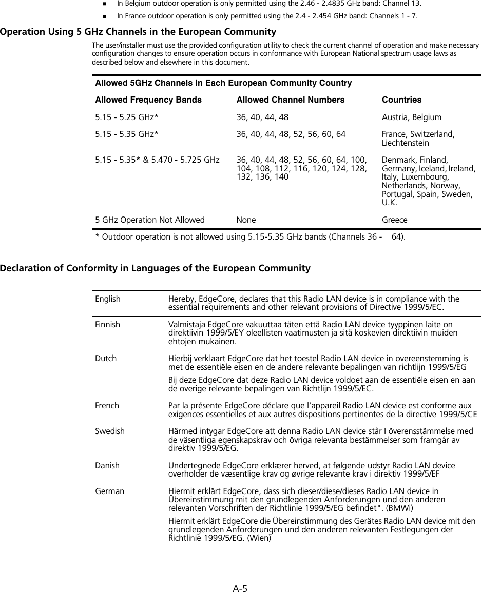
![A-12A copy of the signed Declaration of Conformity can be downloaded from the Product Support web page for the 3Com Outdoor 11a Building to Building Bridge and 11bg Access Point, Model WL-546 (3CRWEASYA73) at http://www.3com.com.Also available at http://support.3com.com/doc/WL-546_EU_DOC.pdfEU – Restrictions for Use in the 2.4GHz bandThis device may be operated indoors or outdoors in all countries of the European Community using the 2.4GHz band: Channels 1 – 13, except where noted below. In Italy the end-user must apply for a license from the national spectrum authority to operate this device outdoors. In Belgium outdoor operation is only permitted using the 2.46 – 2.4835 GHz band: Channel 13.In France outdoor operation is only permitted using the 2.4 – 2.454 GHz band: Channels 1 – 7.EU – Restrictions for Use in the 5GHz bandThis device may be not be operated outdoors when using the bands 5150-5350MHz (Channels 36, 40, 44, 48, 52, 56, 50, 64).In Italy the end-user must apply for a license from the national spectrum authority to operate this device outdoors. To remain in conformance with European spectrum usage laws for Wireless LAN operation, the above 5GHz channel limitations apply. The user should check the current channel of operation. If operation is occurring outside of the allowable frequencies as listed above, the user must cease operating the Managed Access Point at that location and consult the local technical support staff responsible for the wireless network.The 5GHz Turbo mode feature is not allowed for operation in any European Community country.This device must be used with the radar detection feature required for European Community operation in the 5GHz bands. This device will avoid operating on a channel occupied by any radar system in the area. The presence of nearby radar operation may result in temporary interruption in communications of this device. The Access Point’s radar detection feature will automatically restart operation on a channel free of radar. You may consult with the local technical support staff responsible for the wireless network to ensure the Access Point device(s) are properly configured for European Community operation.Slovensky [Slovak] 3Com Corporation týmto vyhlasuje, že RLAN device splna základné požiadavky a všetky príslušné ustanovenia Smernice 1999/5/ES.Suomi [Finnish] 3Com Corporation vakuuttaa täten että RLAN device tyyppinen laite on direktiivin 1999/5/EY oleellisten vaatimusten ja sitä koskevien direktiivin muiden ehtojen mukainen.Allowed Frequency BandsAllowed Channel Numbers Countries5.15-5.35GHz 36, 40, 44, 48, 52, 56, 60, 64 Czech Republic, France5.15-5.35 & 5.470-5.725GHz36, 40, 44, 48, 52, 56, 60, 64, 100, 104, 108, 112, 116, 120, 124, 128, 132, 136, 140Austria, Belgium, Bulgaria, Cyprus, Denmark, Estonia, Finland, Germany, Greece, Hungary, Iceland, Ireland, Italy, Latvia, Liechtenstein, Lithuania, Luxembourg, Malta, Netherlands, Norway, Poland, Portugal, Slovakia, Slovenia, Spain, Sweden, Switzerland, U.K.](https://usermanual.wiki/Hewlett-Packard-Enterprise/WL575.Users-Manual-2/User-Guide-670064-Page-120.png)


Users Manual2


![Command Line Interface7-387DHCP Relay CommandsDynamic Host Configuration Protocol (DHCP) can dynamically allocate an IP address and other configuration information to network clients that broadcast a request. To receive the broadcast request, the DHCP server would normally have to be on the same subnet as the client. However, when the bridge’s DHCP relay agent is enabled, received client requests can be forwarded directly by the bridge to a known DHCP server on another subnet. Responses from the DHCP server are returned to the bridge, which then broadcasts them back to clients.dhcp-relay enableThis command enables the bridge’s DHCP relay agent. Use the no form to disable the agent.Syntax[no] dhcp-relay enableDefault Setting DisabledCommand Mode Global ConfigurationCommand Usage • For the DHCP relay agent to function, the primary DHCP server must be configured using the dhcp-relay primary command. A secondary DHCP server does not need to be configured, but it is recommended.• If there is no response from the primary DHCP server, and a secondary server has been configured, the agent will then attempt to send DHCP requests to the secondary server.Example Table 7-8. DHCP Relay CommandsCommand Function Mode Pagedhcp-relay enable Enables the DHCP relay agent GC 7-38dhcp-relay Sets the primary and secondary DHCP server address GC 7-39show dhcp-relay Shows current DHCP relay configuration settings Exec 7-39Enterprise AP(config)#dhcp-relay enableEnterprise AP(config)#](https://usermanual.wiki/Hewlett-Packard-Enterprise/WL575.Users-Manual2/User-Guide-670084-Page-8.png)


![SNMP Commands7-417snmp-server communityThis command defines the community access string for the Simple Network Management Protocol. Use the no form to remove the specified community string.Syntaxsnmp-server community string [ro | rw]no snmp-server community string•string - Community string that acts like a password and permits access to the SNMP protocol. (Maximum length: 23 characters, case sensitive)•ro - Specifies read-only access. Authorized management stations are only able to retrieve MIB objects. •rw - Specifies read/write access. Authorized management stations are able to both retrieve and modify MIB objects.Default Setting • public - Read-only access. Authorized management stations are only able to retrieve MIB objects.• private - Read/write access. Authorized management stations are able to both retrieve and modify MIB objects.Command Mode Global ConfigurationCommand Usage If you enter a community string without the ro or rw option, the default is read only.Example snmp-server contactThis command sets the system contact string. Use the no form to remove the system contact information.Syntaxsnmp-server contact stringno snmp-server contactstring - String that describes the system contact. (Maximum length: 255 characters)Default Setting NoneEnterprise AP(config)#snmp-server community alpha rwEnterprise AP(config)#](https://usermanual.wiki/Hewlett-Packard-Enterprise/WL575.Users-Manual2/User-Guide-670084-Page-11.png)

![Command Line Interface7-487snmp-server targetsThis command configures SNMP v3 notification targets. Use the no form to delete an SNMP v3 target.Syntaxsnmp-server targets <target-id> <ip-addr> <sec-name> [version {3}] [udp-port {port-number}] [notification-type {TRAP}]no snmp-server targets <target-id>•target-id - A user-defined name that identifies a receiver of SNMP notifications. (Maximum length: 32 characters)•ip-addr - Specifies the IP address of the management station to receive notifications.•sec-name - The defined SNMP v3 user name that is to receive notifications.•version - The SNMP version of notifications. Currently only version 3 is supported in this command.•udp-port - The UDP port that is used on the receiving management station for notifications.•notification-type - The type of notification that is sent. Currently only TRAP is supported.Default Setting NoneCommand Mode Global ConfigurationCommand Usage • The bridge supports up to 10 SNMP v3 target IDs.• The SNMP v3 user name that is specified in the target must first be configured using the snmp-server user command.Example Enterprise AP(config)#snmp-server targets mytraps 192.168.1.33 chrisEnterprise AP(config)#](https://usermanual.wiki/Hewlett-Packard-Enterprise/WL575.Users-Manual2/User-Guide-670084-Page-18.png)
![SNMP Commands7-497snmp-server filterThis command configures SNMP v3 notification filters. Use the no form to delete an SNMP v3 filter or remove a subtree from a filter.Syntaxsnmp-server filter <filter-id> <include | exclude> <subtree> [mask {mask}]no snmp-server filter <filter-id> [subtree]•filter-id - A user-defined name that identifies an SNMP v3 notification filter. (Maximum length: 32 characters)•include - Defines a filter type that includes objects in the MIB subtree.•exclude - Defines a filter type that excludes objects in the MIB subtree.•subtree - The part of the MIB subtree that is to be filtered.•mask - An optional hexadecimal value bit mask to define objects in the MIB subtree. Default Setting NoneCommand Mode Global ConfigurationCommand Usage • The bridge allows up to 10 notification filters to be created. Each filter can be defined by up to 20 MIB subtree ID entries.• Use the command more than once with the same filter ID to build a filter that includes or excludes multiple MIB objects. Note that the filter entries are applied in the sequence that they are defined.• The MIB subtree must be defined in the form “.1.3.6.1” and always start with a “.”.• The mask is a hexadecimal value with each bit masking the corresponding ID in the MIB subtree. A “1” in the mask indicates an exact match and a “0” indicates a “wild card.” For example, a mask value of 0xFFBF provides a bit mask “1111 1111 1011 1111.” If applied to the subtree 1.3.6.1.2.1.2.2.1.1.23, the zero corresponds to the 10th subtree ID. When there are more subtree IDs than bits in the mask, the mask is padded with ones.Example Enterprise AP(config)#snmp-server filter trapfilter include .1Enterprise AP(config)#snmp-server filter trapfilter exclude .1.3.6.1.2.1.2.2.1.1.23](https://usermanual.wiki/Hewlett-Packard-Enterprise/WL575.Users-Manual2/User-Guide-670084-Page-19.png)
![Command Line Interface7-527Example show snmp targetThis command displays the SNMP v3 notification target settings.Syntaxshow snmp targetCommand Mode ExecExample show snmp filterThis command displays the SNMP v3 notification filter settings.Syntaxshow snmp filter [filter-id] •filter-id - A user-defined name that identifies an SNMP v3 notification filter. (Maximum length: 32 characters)Command Mode ExecExample Enterprise AP#show snmp group-assignmentsGroupName :RWPrivUserName :chrisEnterprise AP#Enterprise AP#Enterprise AP#show snmp targetHost ID : mytrapsUser : chrisIP Address : 192.168.1.33UDP Port : 162=============================Enterprise AP#Enterprise AP#show snmp filterFilter: trapfilter Type: include Subtree: iso.3.6.1.2.1.2.2.1 Type: exclude Subtree: iso.3.6.1.2.1.2.2.1.1.23=============================Enterprise AP#](https://usermanual.wiki/Hewlett-Packard-Enterprise/WL575.Users-Manual2/User-Guide-670084-Page-22.png)


![Flash/File Commands7-577The following example shows how to download a configuration file: deleteThis command deletes a file or image.Syntaxdelete <filename>filename - Name of the configuration file or image name.Default Setting NoneCommand Mode ExecCaution: Beware of deleting application images from flash memory. At least one application image is required in order to boot the bridge. If there are multiple image files in flash memory, and the one used to boot the bridge is deleted, be sure you first use the bootfile command to update the application image file booted at startup before you reboot the bridge.Example This example shows how to delete the test.cfg configuration file from flash memory.Related Commandsbootfile (7-55)dir (7-58)Enterprise AP#copy tftp file1. Application image2. Config file3. Boot block imageSelect the type of download<1,2,3>: [1]:2TFTP Source file name:syscfgTFTP Server IP:192.168.1.19Enterprise AP#Enterprise AP#delete test.cfgAre you sure you wish to delete this file? <y/n>:Enterprise AP#](https://usermanual.wiki/Hewlett-Packard-Enterprise/WL575.Users-Manual2/User-Guide-670084-Page-27.png)
![RADIUS Client7-597RADIUS ClientRemote Authentication Dial-in User Service (RADIUS) is a logon authentication protocol that uses software running on a central server to control access for RADIUS-aware devices to the network. An authentication server contains a database of credentials, such as users names and passwords, for each wireless client that requires access to the bridge.radius-server addressThis command specifies the primary and secondary RADIUS servers. Syntaxradius-server [secondary] address <host_ip_address | host_name>•secondary - Secondary server.•host_ip_address - IP address of server.•host_name - Host name of server. (Range: 1-20 characters)Default Setting NoneTable 7-11. RADIUS ClientCommand Function Mode Pageradius-server address Specifies the RADIUS server GC 7-59radius-server port Sets the RADIUS server network port GC 7-60radius-server key Sets the RADIUS encryption key GC 7-60radius-server retransmit Sets the number of retries GC 7-61radius-server timeout Sets the interval between sending authentication requests GC 7-61radius-server port-accounting Sets the RADIUS Accounting server network port GC 7-62radius-server timeout-interim Sets the interval between transmitting accounting updates to the RADIUS server GC 7-62radius-server radius-mac-format Sets the format for specifying MAC addresses on the RADIUS server GC 7-63radius-server vlan-format Sets the format for specifying VLAN IDs on the RADIUS server GC 7-63show radius Shows the current RADIUS settings Exec 7-64](https://usermanual.wiki/Hewlett-Packard-Enterprise/WL575.Users-Manual2/User-Guide-670084-Page-29.png)
![Command Line Interface7-607Command Mode Global ConfigurationExample radius-server portThis command sets the RADIUS server network port. Syntaxradius-server [secondary] port <port_number>•secondary - Secondary server.•port_number - RADIUS server UDP port used for authentication messages. (Range: 1024-65535)Default Setting 1812Command Mode Global ConfigurationExample radius-server keyThis command sets the RADIUS encryption key. Syntax radius-server [secondary] key <key_string>•secondary - Secondary server.•key_string - Encryption key used to authenticate logon access for client. Do not use blank spaces in the string. (Maximum length: 20 characters)Default Setting DEFAULTCommand Mode Global ConfigurationExample Enterprise AP(config)#radius-server address 192.168.1.25Enterprise AP(config)#Enterprise AP(config)#radius-server port 181Enterprise AP(config)#Enterprise AP(config)#radius-server key greenEnterprise AP(config)#](https://usermanual.wiki/Hewlett-Packard-Enterprise/WL575.Users-Manual2/User-Guide-670084-Page-30.png)
![RADIUS Client7-617radius-server retransmitThis command sets the number of retries. Syntaxradius-server [secondary] retransmit number_of_retries•secondary - Secondary server.•number_of_retries - Number of times the bridge will try to authenticate logon access via the RADIUS server. (Range: 1 - 30)Default Setting 3Command Mode Global ConfigurationExample radius-server timeoutThis command sets the interval between transmitting authentication requests to the RADIUS server. Syntax radius-server [secondary] timeout number_of_seconds•secondary - Secondary server.•number_of_seconds - Number of seconds the bridge waits for a reply before resending a request. (Range: 1-60)Default Setting 5Command Mode Global ConfigurationExample Enterprise AP(config)#radius-server retransmit 5Enterprise AP(config)#Enterprise AP(config)#radius-server timeout 10Enterprise AP(config)#](https://usermanual.wiki/Hewlett-Packard-Enterprise/WL575.Users-Manual2/User-Guide-670084-Page-31.png)
![Command Line Interface7-627radius-server port-accountingThis command sets the RADIUS Accounting server network port. Syntaxradius-server [secondary] port-accounting <port_number>•secondary - Secondary server. If secondary is not specified, then the bridge assumes you are configuring the primary RADIUS server.•port_number - RADIUS Accounting server UDP port used for accounting messages. (Range: 0 or 1024-65535)Default Setting 0 (disabled)Command Mode Global ConfigurationCommand Usage • When the RADIUS Accounting server UDP port is specified, a RADIUS accounting session is automatically started for each user that is successfully authenticated to the bridge.Example radius-server timeout-interimThis command sets the interval between transmitting accounting updates to the RADIUS server.Syntax radius-server [secondary] timeout-interim <number_of_seconds>•secondary - Secondary server.•number_of_seconds - Number of seconds the bridge waits between transmitting accounting updates. (Range: 60-86400)Default Setting 3600Command Mode Global ConfigurationCommand Usage • The bridge sends periodic accounting updates after every interim period until the user logs off and a “stop” message is sent.Enterprise AP(config)#radius-server port-accounting 1813Enterprise AP(config)#](https://usermanual.wiki/Hewlett-Packard-Enterprise/WL575.Users-Manual2/User-Guide-670084-Page-32.png)


![Command Line Interface7-727Command ModeGlobal ConfigurationExampleRelated Commands802.1x-supplicant user (7-68)mac-authentication serverThis command sets address filtering to be performed with local or remote options. Use the no form to disable MAC address authentication.Syntaxmac-authentication server [local | remote]•local - Authenticate the MAC address of wireless clients with the local authentication database during 802.11 association.•remote - Authenticate the MAC address of wireless clients with the RADIUS server during 802.1X authentication.DefaultDisabledCommand ModeGlobal ConfigurationExampleRelated Commandsaddress filter entry (7-71)radius-server address (7-59)802.1x-supplicant user (7-68)mac-authentication session-timeoutThis command sets the interval at which associated clients will be re-authenticated with the RADIUS server authentication database. Use the no form to disable reauthentication.Syntaxmac-authentication session-timeout <minutes>minutes - Re-authentication interval. (Range: 0-1440)Enterprise AP(config)#address filter delete 00-70-50-cc-99-1b Enterprise AP(config)#Enterprise AP(config)#mac-authentication server remoteEnterprise AP(config)#](https://usermanual.wiki/Hewlett-Packard-Enterprise/WL575.Users-Manual2/User-Guide-670084-Page-42.png)

![Filtering Commands7-757filter uplink enableThis command enables filtering of MAC addresses from the Ethernet port.Syntax[no] filter uplink enableDefaultDisabledCommand ModeGlobal ConfigurationExamplefilter uplinkThis command adds or deletes MAC addresses from the uplink filtering table.Syntaxfilter uplink <add | delete> MAC addressMAC address - Specifies a MAC address in the form xx-xx-xx-xx-xx-xx. A maximum of eight addresses can be added to the filtering table.DefaultDisabledCommand ModeGlobal ConfigurationExamplefilter ethernet-type enableThis command checks the Ethernet type on all incoming and outgoing Ethernet packets against the protocol filtering table. Use the no form to disable this feature.Syntaxfilter ethernet-type enableno filter ethernet-type enableDefaultDisabledCommand ModeEnterprise AP(config)#filter uplink enableEnterprise AP(config)#Enterprise AP(config)#filter uplink add 00-12-34-56-78-9aEnterprise AP(config)#](https://usermanual.wiki/Hewlett-Packard-Enterprise/WL575.Users-Manual2/User-Guide-670084-Page-45.png)


![WDS Bridge Commands7-817show bridge filter-entryThis command displays current entries in the WDS forwarding table.Command Mode ExecExample show bridge linkThis command displays WDS bridge link and spanning tree settings for specified interfaces.Syntaxshow bridge link <ethernet | wireless <a | g> [index]>•ethernet - Specifies the Ethernet interface.•wireless - Specifies a wireless interface.-a - The 802.11a radio interface.-g - The 802.11g radio interface.-index - The index number of a bridge link. (Range: 1 - 6)Command Mode ExecEnterprise AP#show bridge filter-entrymax entry numbers =512current entry nums =13**************************************************************************************************** Bridge MAC Addr Table ************************************************************************************************************| MAC | Port |Fwd_type| VlanID|origin life|remain Life| Type | 01 80 c2 00 00 00 0 5 4095 300 300 Static 01 80 c2 00 00 03 0 5 4095 300 300 Static 00 30 f1 f0 9b 20 1 0 1 300 300 Static 00 30 f1 f0 9b 21 1 0 1 300 300 Static 00 30 f1 f0 9b 22 1 0 1 300 300 Static 00 30 f1 f0 9b 23 1 0 1 300 300 Static 00 30 f1 f0 9b 24 1 0 1 300 300 Static 00 30 f1 f0 9b 25 1 0 1 300 300 Static 00 30 f1 f0 9b 26 1 0 1 300 300 Static 00 30 f1 f0 9b 27 1 0 1 300 300 Static 00 30 f1 2f be 30 1 3 0 300 175 Dynamic 00 30 f1 f0 9a 9c 1 0 1 300 300 Static ff ff ff ff ff ff 0 4 4095 300 300 StaticEnterprise AP#](https://usermanual.wiki/Hewlett-Packard-Enterprise/WL575.Users-Manual2/User-Guide-670084-Page-51.png)

![Command Line Interface7-847bridge stp forwarding-delayUse this command to configure the spanning tree bridge forward time globally for the wireless bridge. Use the no form to restore the default.Syntax bridge stp forwarding-delay <seconds>no bridge stp forwarding-delayseconds - Time in seconds. (Range: 4 - 30 seconds)The minimum value is the higher of 4 or [(max-age / 2) + 1]. Default Setting 15 secondsCommand Mode Global ConfigurationCommand Usage This command sets the maximum time (in seconds) the root device will wait before changing states (i.e., discarding to learning to forwarding). This delay is required because every device must receive information about topology changes before it starts to forward frames. In addition, each port needs time to listen for conflicting information that would make it return to the discarding state; otherwise, temporary data loops might result.Example bridge stp hello-timeUse this command to configure the spanning tree bridge hello time globally for the wireless bridge. Use the no form to restore the default.Syntax bridge stp hello-time <time>no bridge stp hello-timetime - Time in seconds. (Range: 1-10 seconds). The maximum value is the lower of 10 or [(max-age / 2) -1]. Default Setting 2 secondsCommand Mode Global ConfigurationCommand Usage This command sets the time interval (in seconds) at which the root device transmits a configuration message.Enterprise AP(config)#bridge stp forwarding-delay 20Enterprise AP(config)#](https://usermanual.wiki/Hewlett-Packard-Enterprise/WL575.Users-Manual2/User-Guide-670084-Page-54.png)
![Spanning Tree Commands7-857Example bridge stp max-ageUse this command to configure the spanning tree bridge maximum age globally for the wireless bridge. Use the no form to restore the default.Syntax bridge stp max-age <seconds>no bridge stp max-ageseconds - Time in seconds. (Range: 6-40 seconds)The minimum value is the higher of 6 or [2 x (hello-time + 1)].The maximum value is the lower of 40 or [2 x (forward-time - 1)].Default Setting 20 secondsCommand Mode Global ConfigurationCommand Usage This command sets the maximum time (in seconds) a device can wait without receiving a configuration message before attempting to reconfigure. All device ports (except for designated ports) should receive configuration messages at regular intervals. Any port that ages out STP information (provided in the last configuration message) becomes the designated port for the attached LAN. If it is a root port, a new root port is selected from among the device ports attached to the network.Example bridge stp priorityUse this command to configure the spanning tree priority globally for the wireless bridge. Use the no form to restore the default.Syntax bridge stp priority<priority>no bridge stp prioritypriority - Priority of the bridge. (Range: 0 - 65535) Default Setting 32768Enterprise AP(config)#bridge stp hello-time 5Enterprise AP(config)#Enterprise AP(config)#bridge stp max-age 40Enterprise AP(config)#](https://usermanual.wiki/Hewlett-Packard-Enterprise/WL575.Users-Manual2/User-Guide-670084-Page-55.png)
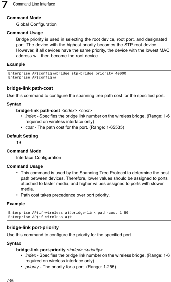

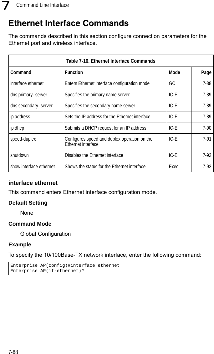

![Command Line Interface7-927shutdown This command disables the Ethernet interface. To restart a disabled interface, use the no form.Syntax shutdownno shutdownDefault Setting Interface enabledCommand Mode Interface Configuration (Ethernet)Command Usage This command allows you to disable the Ethernet port due to abnormal behavior (e.g., excessive collisions), and reenable it after the problem has been resolved. You may also want to disable the Ethernet port for security reasons. Example The following example disables the Ethernet port.show interface ethernetThis command displays the status for the Ethernet interface.Syntaxshow interface [ethernet]Default Setting Ethernet interfaceCommand Mode ExecEnterprise AP(if-ethernet)#shutdownEnterprise AP(if-ethernet)#](https://usermanual.wiki/Hewlett-Packard-Enterprise/WL575.Users-Manual2/User-Guide-670084-Page-62.png)

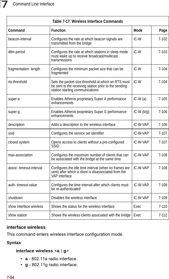
![Wireless Interface Commands7-957Default Setting NoneCommand Mode Global Configuration Example To specify the 802.11a interface, enter the following command:vapThis command provides access to the VAP (Virtual bridge) interface configuration mode.Syntaxvap <vap-id>vap-id - The number that identifies the VAP interface. (Options: 0-7)Default Setting NoneCommand Mode Interface Configuration (Wireless)ExamplespeedThis command configures the maximum data rate at which the bridge transmits unicast packets. Syntaxspeed <speed>speed - Maximum access speed allowed for wireless clients. (Options for 802.11a: 6, 9, 12, 18, 24, 36, 48, 54 Mbps) (Options for 802.11b/g: 1, 2, 5.5, 6, 9, 11, 12, 18, 24, 36, 48, 54 Mbps)Enterprise AP(config)#interface wireless aEnterprise AP(if-wireless a)#Enterprise AP(if-wireless g)#vap 0Enterprise AP(if-wireless g: VAP[0])#](https://usermanual.wiki/Hewlett-Packard-Enterprise/WL575.Users-Manual2/User-Guide-670084-Page-65.png)


![Command Line Interface7-1007ExamplepreambleThis command sets the length of the signal preamble that is used at the start of a 802.11b/g data transmission.Syntaxpreamble [long | short-or-long]•long - Sets the preamble to long (192 microseconds).•short-or-long - Sets the preamble to short if no 802.11b clients are detected (96 microseconds).Default SettingShort-or-LongCommand ModeInterface Configuration (Wireless - 802.11b/g)Command Usage• Using a short preamble instead of a long preamble can increase data throughput on the bridge, but requires that all clients can support a short preamble.• Set the preamble to long to ensure the bridge can support all 802.11b and 802.11g clients.Exampleantenna controlThis command selects the use of two diversity antennas or a single antenna for the radio interface.Syntaxantenna control <diversity | left | right>•diversity - The radio uses both antennas in a diversity system. Select this method when the Antenna ID is set to “Default Antenna” to use the bridge's integrated antennas. The bridge does not support external diversity antennas.•left - The radio only uses the antenna on the left side (the side farthest from the bridge LEDs). The bridge does not support an external antenna connection on its left antenna. Therefore, this method is not valid for the bridge.Enterprise AP(if-wireless g)#radio-mode gEnterprise AP(if-wireless g)#Enterprise AP(if-wireless g)#preamble shortEnterprise AP(if-wireless g)#](https://usermanual.wiki/Hewlett-Packard-Enterprise/WL575.Users-Manual2/User-Guide-670084-Page-70.png)

![Wireless Interface Commands7-1057Default Setting 2347Command Mode Interface Configuration (Wireless)Command Usage • If the threshold is set to 0, the bridge always sends RTS signals. If set to 2347, the bridge never sends RTS signals. If set to any other value, and the packet size equals or exceeds the RTS threshold, the RTS/CTS (Request to Send / Clear to Send) mechanism will be enabled.• The bridge sends RTS frames to a receiving station to negotiate the sending of a data frame. After receiving an RTS frame, the station sends a CTS frame to notify the sending station that it can start sending data. • bridges contending for the wireless medium may not be aware of each other. The RTS/CTS mechanism can solve this “Hidden Node” problem.Examplesuper-a This command enables Atheros proprietary Super A performance enhancements. Use the no form to disable this function.Syntax[no] super-a Default Setting DisabledCommand Mode Interface Configuration (Wireless - 802.11a)Command Usage Super A enhancements include bursting, compression, and fast frames. Maximum throughput ranges between 40 to 60 Mbps for connections to Atheros-compatible clients.ExampleEnterprise AP(if-wireless g)#rts-threshold 256Enterprise AP(if-wireless g)#Enterprise AP(if-wireless a)#super aEnterprise AP(if-wireless a)#](https://usermanual.wiki/Hewlett-Packard-Enterprise/WL575.Users-Manual2/User-Guide-670084-Page-75.png)
![Command Line Interface7-1067super-g This command enables Atheros proprietary Super G performance enhancements. Use the no form to disable this function.Syntax[no] super-g Default Setting DisabledCommand Mode Interface Configuration (Wireless - 802.11g)Command Usage These enhancements include bursting, compression, fast frames and dynamic turbo. Maximum throughput ranges between 40 to 60 Mbps for connections to Atheros-compatible clients.Exampledescription This command adds a description to a the wireless interface. Use the no form to remove the description.Syntaxdescription <string>no descriptionstring - Comment or a description for this interface. (Range: 1-80 characters)Default Setting NoneCommand Mode Interface Configuration (Wireless-VAP)ExampleEnterprise AP(if-wireless a)#super gEnterprise AP(if-wireless a)#Enterprise AP(if-wireless g: VAP[0])#description RD-AP#3Enterprise AP(if-wireless g: VAP[0])#](https://usermanual.wiki/Hewlett-Packard-Enterprise/WL575.Users-Manual2/User-Guide-670084-Page-76.png)
![Wireless Interface Commands7-1077ssidThis command configures the service set identifier (SSID). Syntaxssid <string>string - The name of a basic service set supported by the bridge. (Range: 1 - 32 characters)Default Setting 802.11a Radio: VAP_TEST_11A (0 to 3)802.11g Radio: VAP_TEST_11G (0 to 3)Command Mode Interface Configuration (Wireless-VAP)Command Usage Clients that want to connect to the wireless network via an bridge must set their SSIDs to the same as that of the bridge.Exampleclosed-systemThis command prohibits access to clients without a pre-configured SSID. Use the no form to disable this feature.Syntaxclosed-system no closed-systemDefault Setting DisabledCommand Mode Interface Configuration (Wireless-VAP)Command Usage When closed system is enabled, the bridge will not include its SSID in beacon messages. Nor will it respond to probe requests from clients that do not include a fixed SSID.ExampleEnterprise AP(if-wireless g: VAP[0])#ssid RD-AP#3Enterprise AP(if-wireless g)#Enterprise AP(if-wireless g: VAP[0])#closed-systemEnterprise AP(if-wireless g)#](https://usermanual.wiki/Hewlett-Packard-Enterprise/WL575.Users-Manual2/User-Guide-670084-Page-77.png)
![Command Line Interface7-1087max-association This command configures the maximum number of clients that can be associated with the bridge at the same time.Syntaxmax-association <count>count - Maximum number of associated stations. (Range: 0-64)Default Setting 64Command Mode Interface Configuration (Wireless-VAP)Example assoc-timeout-intervalThis command configures the idle time interval (when no frames are sent) after which the client is disassociated from the VAP interface.Syntaxassoc-timeout-interval <minutes>minutes - The number of minutes of inactivity before disassociation. (Range: 5-60)Default Setting 30Command Mode Interface Configuration (Wireless-VAP)Exampleauth-timeout-valueThis command configures the time interval within which clients must complete authentication to the VAP interface.Syntaxauth-timeout-value <minutes>minutes - The number of minutes before re-authentication. (Range: 5-60)Enterprise AP(if-wireless g: VAP[0])#max-association 32Enterprise AP(if-wireless g)#Enterprise AP(if-wireless g: VAP[0])#association-timeout-interval 20Enterprise AP(if-wireless g: VAP[0])#](https://usermanual.wiki/Hewlett-Packard-Enterprise/WL575.Users-Manual2/User-Guide-670084-Page-78.png)
![Wireless Interface Commands7-1097Default Setting 60Command Mode Interface Configuration (Wireless-VAP)Exampleshutdown This command disables the wireless interface. Use the no form to restart the interface.Syntax shutdownno shutdownDefault Setting Interface enabledCommand Mode Interface Configuration (Wireless-VAP)Command UsageYou must first enable VAP interface 0 before you can enable VAP interfaces 1, 2, 3, 4, 5, 6, or 7.Example Enterprise AP(if-wireless g: VAP[0])#auth-timeout-value 40Enterprise AP(if-wireless g: VAP[0])#Enterprise AP(if-wireless g: VAP[0])#shutdownEnterprise AP(if-wireless g)#](https://usermanual.wiki/Hewlett-Packard-Enterprise/WL575.Users-Manual2/User-Guide-670084-Page-79.png)


![Command Line Interface7-1127show stationThis command shows the wireless clients associated with the bridge.Command Mode ExecExample Enterprise AP#show stationStation Table Information========================================================if-wireless A VAP [0] :802.11a Channel : 60No 802.11a Channel Stations....if-wireless G VAP [0] :802.11g Channel : 1802.11g Channel Station TableStation Address : 00-04-23-94-9A-9C VLAN ID: 0Authenticated Associated Forwarding KeyTypeTRUE FALSE FALSE NONECounters:pkts Tx / Rx bytes Tx / Rx 20/ 0 721/ 0Time:Associated LastAssoc LastDisAssoc LastAuth 0 0 0 0if-wireless G VAP [1] :802.11g Channel : 1No 802.11g Channel Stations....Enterprise AP#](https://usermanual.wiki/Hewlett-Packard-Enterprise/WL575.Users-Manual2/User-Guide-670084-Page-82.png)
![Rogue AP Detection Commands7-1137Rogue AP Detection CommandsA “rogue AP” is either an bridge that is not authorized to participate in the wireless network, or an bridge that does not have the correct security configuration. Rogue APs can potentially allow unauthorized users access to the network. Alternatively, client stations may mistakenly associate to a rogue AP and be prevented from accessing network resources. Rogue APs may also cause radio interference and degrade the wireless LAN performance.The bridge can be configured to periodically scan all radio channels and find other bridges within range. A database of nearby bridges is maintained where any rogue APs can be identified.rogue-ap enableThis command enables the periodic detection of nearby bridges. Use the no form to disable periodic detection.Syntax[no] rogue-ap enableDefault SettingDisabledCommand Mode Interface Configuration (Wireless)Command Usage • While the bridge scans a channel for rogue APs, wireless clients will not be able to connect to the bridge. Therefore, avoid frequent scanning or scans of a long duration unless there is a reason to believe that more intensive scanning is required to find a rogue AP.Table 7-18. Rogue AP Detection CommandsCommand Function Mode Pagerogue-ap enable Enables the periodic detection of other nearby bridges GC 7-113rogue-ap authenticate Enables identification of all bridges GC 7-114rogue-ap duration Sets the duration that all channels are scanned GC 7-114rogue-ap interval Sets the time between each scan GC 7-115rogue-ap scan Forces an immediate scan of all radio channels GC 7-116show rogue-ap Shows the current database of detected bridges Exec 7-117](https://usermanual.wiki/Hewlett-Packard-Enterprise/WL575.Users-Manual2/User-Guide-670084-Page-83.png)
![Command Line Interface7-1147• A “rogue AP” is either an bridge that is not authorized to participate in the wireless network, or an bridge that does not have the correct security configuration. Rogue bridges can be identified by unknown BSSID (MAC address) or SSID configuration. A database of nearby bridges should therefore be maintained on a RADIUS server, allowing any rogue APs to be identified (see “rogue-ap authenticate” on page 7-114). The rogue AP database can be viewed using the show rogue-ap command.• The bridge sends Syslog messages for each detected bridge during a rogue AP scan.Example rogue-ap authenticateThis command forces the unit to authenticate all bridges on the network. Use the no form to disable this function.Syntax[no] rogue-ap authenticateDefault SettingDisabledCommand Mode Interface Configuration (Wireless)Command Usage Enabling authentication in conjunction with a database of approved bridges stored on a RADIUS server allows the bridge to discover rogue APs. With authentication enabled and a configure RADIUS server, the bridge checks the MAC address/Basic Service Set Identifier (BSSID) of each bridge that it finds against a RADIUS server to determine whether the bridge is allowed. With authentication disabled, the bridge can identify its neighboring bridges only; it cannot identify whether the bridges are allowed or are rogues. If you enable authentication, you should also configure a RADIUS server for this bridge (see “Radius” on page 6-7).Example rogue-ap durationThis command sets the scan duration for detecting bridges.Enterprise AP(if-wireless g)#rogue-ap enableconfigure either syslog or trap or both to receive the rogue APs detected.Enterprise AP(if-wireless g)#Enterprise AP(if-wireless g)#rogue-ap authenticateEnterprise AP(if-wireless g)#](https://usermanual.wiki/Hewlett-Packard-Enterprise/WL575.Users-Manual2/User-Guide-670084-Page-84.png)


![Command Line Interface7-1207ExampleRelated Commandsencryption (7-120)key (7-121)encryption This command enables data encryption for wireless communications. Use the no form to disable data encryption.Syntaxencryptionno encryptionDefault Setting disabledCommand Mode Interface Configuration (Wireless-VAP)Command Usage • Wired Equivalent Privacy (WEP) is implemented in this device to prevent unauthorized access to your wireless network. For more secure data transmissions, enable encryption with this command, and set at least one static WEP key with the key command. • The WEP settings must be the same on each client in your wireless network.• Note that WEP protects data transmitted between wireless nodes, but does not protect any transmissions over your wired network or over the Internet.• You must enable data encryption in order to enable all types of encryption (WEP, TKIP, and AES-CCMP) in the bridge. ExampleRelated Commandskey (7-121)Enterprise AP(if-wireless g: VAP[0])#auth shared-keyEnterprise AP(if-wireless g)#Enterprise AP(if-wireless g: VAP[0])#encryptionEnterprise AP(if-wireless g)#](https://usermanual.wiki/Hewlett-Packard-Enterprise/WL575.Users-Manual2/User-Guide-670084-Page-90.png)
![Command Line Interface7-1227transmit-keyThis command sets the index of the key to be used for encrypting data frames for broadcast or multicast traffic transmitted from the VAP to wireless clients.Syntaxtransmit-key <index>index - Key index. (Range: 1-4)Default Setting 1Command Mode Interface Configuration (Wireless-VAP)Command Usage • If you use WEP key encryption option, the bridge uses the transmit key to encrypt multicast and broadcast data signals that it sends to client devices. Other keys can be used for decryption of data from clients.• When using IEEE 802.1X, the bridge uses a dynamic key to encrypt unicast and broadcast messages to 802.1X-enabled clients. However, because the bridge sends the keys during the 802.1X authentication process, these keys do not have to appear in the client’s key list.• In a mixed-mode environment with clients using static and dynamic keys, select transmit key index 2, 3, or 4. The bridge uses transmit key index 1 for the generation of dynamic keys.Example Enterprise AP(if-wireless g: VAP[0])#transmit-key 2Enterprise AP(if-wireless g)#](https://usermanual.wiki/Hewlett-Packard-Enterprise/WL575.Users-Manual2/User-Guide-670084-Page-92.png)
![Command Line Interface7-1247• AES-CCMP (Advanced Encryption Standard Counter-Mode/CBCMAC Protocol): WPA2 is backward compatible with WPA, including the same 802.1X and PSK modes of operation and support for TKIP encryption. The main enhancement is its use of AES Counter-Mode encryption with Cipher Block Chaining Message Authentication Code (CBC-MAC) for message integrity. The AES Counter-Mode/CBCMAC Protocol (AES-CCMP) provides extremely robust data confidentiality using a 128-bit key. The AES-CCMP encryption cipher is specified as a standard requirement for WPA2. However, the computational intensive operations of AES-CCMP requires hardware support on client devices. Therefore to implement WPA2 in the network, wireless clients must be upgraded to WPA2-compliant hardware.Example mic_mode This command specifies how to calculate the Message Integrity Check (MIC). Syntaxmic_mode <hardware | software>•hardware - Uses hardware to calculate the MIC.•software - Uses software to calculate the MIC.Default Setting softwareCommand Mode Interface Configuration (Wireless)Command Usage • The Michael Integrity Check (MIC) is part of the Temporal Key Integrity Protocol (TKIP) encryption used in Wi-Fi Protected Access (WPA) security. The MIC calculation is performed in the bridge for each transmitted packet and this can impact throughput and performance. The bridge supports a choice of hardware or software for MIC calculation. The performance of the bridge can be improved by selecting the best method for the specific deployment. • Using the “hardware” option provides best performance when the number of supported clients is less than 27. • Using the “software” option provides the best performance for a large number of clients on one radio interface. Throughput may be reduced when both 802.11a and 802.11g interfaces are supporting a high number of clients simultaneously.Enterprise AP(if-wireless g: VAP[0])#multicast-cipher TKIPEnterprise AP(if-wireless g)#](https://usermanual.wiki/Hewlett-Packard-Enterprise/WL575.Users-Manual2/User-Guide-670084-Page-94.png)
![Wireless Security Commands7-1257Example wpa-pre-shared-key This command defines a Wi-Fi Protected Access (WPA/WPA2) Pre-shared-key.Syntaxwpa-pre-shared-key <hex | passphrase-key> <value>•hex - Specifies hexadecimal digits as the key input format.•passphrase-key - Specifies an ASCII pass-phrase string as the key input format.•value - The key string. For ASCII input, specify a string between 8 and 63 characters. For HEX input, specify exactly 64 digits.Command Mode Interface Configuration (Wireless-VAP)Command Usage • To support WPA or WPA2 for client authentication, use the auth command to specify the authentication type, and use the wpa-preshared-key command to specify one static key.• If WPA or WPA2 is used with pre-shared-key mode, all wireless clients must be configured with the same pre-shared key to communicate with the bridge’s VAP interface.Example Related Commandsauth (7-118)pmksa-lifetime This command sets the time for aging out cached WPA2 Pairwise Master Key Security Association (PMKSA) information for fast roaming.Syntaxpmksa-lifetime <minutes>minutes - The time for aging out PMKSA information. (Range: 0 - 14400 minutes)Default Setting 720 minutesEnterprise AP(if-wireless a)#mic_mode hardwareEnterprise AP(if-wireless g)#Enterprise AP(if-wireless g: VAP[0])#wpa-pre-shared-key ASCII agoodsecretEnterprise AP(if-wireless g)#](https://usermanual.wiki/Hewlett-Packard-Enterprise/WL575.Users-Manual2/User-Guide-670084-Page-95.png)
![Command Line Interface7-1267Command Mode Interface Configuration (Wireless-VAP)Command Usage • WPA2 provides fast roaming for authenticated clients by retaining keys and other security information in a cache, so that if a client roams away from an bridge and then returns reauthentication is not required. • When a WPA2 client is first authenticated, it receives a Pairwise Master Key (PMK) that is used to generate other keys for unicast data encryption. This key and other client information form a Security Association that the bridge names and holds in a cache. The lifetime of this security association can be configured with this command. When the lifetime expires, the client security association and keys are deleted from the cache. If the client returns to the bridge, it requires full reauthentication.• The bridge can store up to 256 entries in the PMKSA cache. Example pre-authentication This command enables WPA2 pre-authentication for fast secure roaming.Syntaxpre-authentication <enable | disable>•enable - Enables pre-authentication for the VAP interface. •disable - Disables pre-authentication for the VAP interface.Default Setting DisabledCommand Mode Interface Configuration (Wireless-VAP)Command Usage • Each time a client roams to another bridge it has to be fully re-authenticated. This authentication process is time consuming and can disrupt applications running over the network. WPA2 includes a mechanism, known as pre-authentication, that allows clients to roam to a new bridge and be quickly associated. The first time a client is authenticated to a wireless network it has to be fully authenticated. When the client is about to roam to another bridge in the network, the bridge sends pre-authentication messages to the new bridge that include the client’s security association information. Then when the client sends an association request to the new bridge the client is known to be already authenticated, Enterprise AP(if-wireless g: VAP[0])#wpa-pre-shared-key ASCII agoodsecretEnterprise AP(if-wireless g: VAP[0])#](https://usermanual.wiki/Hewlett-Packard-Enterprise/WL575.Users-Manual2/User-Guide-670084-Page-96.png)
![Link Integrity Commands7-1277so it proceeds directly to key exchange and association.• To support pre-authentication, both clients and bridges in the network must be WPA2 enabled.• Pre-authentication requires all bridges in the network to be on the same IP subnet.Example Link Integrity CommandsThe bridge provides a link integrity feature that can be used to ensure that wireless clients are connected to resources on the wired network. The bridge does this by periodically sending Ping messages to a host device in the wired Ethernet network. If the bridge detects that the connection to the host has failed, it disables the radio interfaces, forcing clients to find and associate with another bridge. When the connection to the host is restored, the bridge re-enables the radio interfaces.Enterprise AP(if-wireless g: VAP[0])#wpa-pre-shared-key ASCII agoodsecretEnterprise AP(if-wireless g: VAP[0])#Table 7-20. Link Integrity CommandsCommand Function Mode Pagelink-integrity ping-detect Enables link integrity detection GC 7-128link-integrity ping-host Specifies the IP address of a host device in the wired network GC 7-128link-integrity ping-interval Specifies the time between each Ping sent to the link host GC 7-129link-integrity ping-fail-retry Specifies the number of consecutive failed Ping counts before the link is determined as lost GC 7-129link-integrity ethernet-detect Enables integrity check for Ethernet link GC 7-129show link-integrity Displays the current link integrity configuration Exec 7-130](https://usermanual.wiki/Hewlett-Packard-Enterprise/WL575.Users-Manual2/User-Guide-670084-Page-97.png)
![Command Line Interface7-1287link-integrity ping-detectThis command enables link integrity detection. Use the no form to disable link integrity detection.Syntax[no] link-integrity ping-detectDefault SettingDisabledCommand Mode Global ConfigurationCommand Usage • When link integrity is enabled, the IP address of a host device in the wired network must be specified.• The bridge periodically sends an ICMP echo request (Ping) packet to the link host IP address. When the number of failed responses (either the host does not respond or is unreachable) exceeds the limit set by the link-integrity ping-fail-retry command, the link is determined as lost.Example link-integrity ping-hostThis command configures the link host name or IP address. Use the no form to remove the host setting.Syntaxlink-integrity ping-host <host_name | ip_address>no link-integrity ping-host•host_name - Alias of the host. •ip_address - IP address of the host.Default SettingNoneCommand Mode Global ConfigurationExample Enterprise AP(config)#link-integrity ping-detectEnterprise AP(config)#Enterprise AP(config)#link-integrity ping-host 192.168.1.10Enterprise AP(config)#](https://usermanual.wiki/Hewlett-Packard-Enterprise/WL575.Users-Manual2/User-Guide-670084-Page-98.png)
![Link Integrity Commands7-1297link-integrity ping-intervalThis command configures the time between each Ping sent to the link host. Syntaxlink-integrity ping-interval <interval>interval - The time between Pings. (Range: 5 - 60 seconds)Default Setting30 secondsCommand Mode Global ConfigurationExample link-integrity ping-fail-retryThis command configures the number of consecutive failed Ping counts before the link is determined as lost.Syntaxlink-integrity ping-fail-retry <counts>counts - The number of failed Ping counts before the link is determined as lost. (Range: 1 - 10)Default Setting6Command Mode Global ConfigurationExample link-integrity ethernet-detectThis command enables an integrity check to determine whether or not the bridge is connected to the wired Ethernet.Syntax[no] link-integrity ethernet-detectDefault SettingDisabledEnterprise AP(config)#link-integrity ping-interval 20Enterprise AP(config)#Enterprise AP(config)#link-integrity ping-fail-retry 10Enterprise AP(config)#](https://usermanual.wiki/Hewlett-Packard-Enterprise/WL575.Users-Manual2/User-Guide-670084-Page-99.png)
![IAPP Commands7-1317IAPP CommandsThe command described in this section enables the protocol signaling required to ensure the successful handover of wireless clients roaming between different 802.11f-compliant bridges. In other words, the 802.11f protocol can ensure successful roaming between bridges in a multi-vendor environment.iappThis command enables the protocol signaling required to hand over wireless clients roaming between different 802.11f-compliant bridges. Use the no form to disable 802.11f signaling.Syntax[no] iappDefaultEnabledCommand ModeGlobal ConfigurationCommand UsageThe current 802.11 standard does not specify the signaling required between bridges in order to support clients roaming from one bridge to another. In particular, this can create a problem for clients roaming between bridges from different vendors. This command is used to enable or disable 802.11f handover signaling between different bridges, especially in a multi-vendor environment.ExampleEnterprise AP(config)#iappEnterprise AP(config)#](https://usermanual.wiki/Hewlett-Packard-Enterprise/WL575.Users-Manual2/User-Guide-670084-Page-101.png)
![Command Line Interface7-1327VLAN CommandsThe bridge can enable the support of VLAN-tagged traffic passing between wireless clients and the wired network. Up to 64 VLAN IDs can be mapped to specific wireless clients, allowing users to remain within the same VLAN as they move around a campus site.When VLAN is enabled on the bridge, a VLAN ID (a number between 1 and 4094) can be assigned to each client after successful authentication using IEEE 802.1X and a central RADIUS server. The user VLAN IDs must be configured on the RADIUS server for each user authorized to access the network. If a user does not have a configured VLAN ID, the bridge assigns the user to its own configured native VLAN ID.Caution: When VLANs are enabled, the bridge’s Ethernet port drops all received traffic that does not include a VLAN tag. To maintain network connectivity to the bridge and wireless clients, be sure that the bridge is connected to a device port on a wired network that supports IEEE 802.1Q VLAN tags.The VLAN commands supported by the bridge are listed below. vlanThis command enables VLANs for all traffic. Use the no form to disable VLANs.Syntax[no] vlan enable DefaultDisabledCommand ModeGlobal ConfigurationCommand Description• When VLANs are enabled, the bridge tags frames received from wireless clients with the VLAN ID configured for each client on the RADIUS server. If the VLAN ID has not been configured for a client on the RADIUS server, then the frames are tagged with the bridge’s native VLAN ID.Table 7-21. VLAN CommandsCommand Function Mode Pagevlan Enables a single VLAN for all traffic GC 7-132management-vlanid Configures the management VLAN for the bridge GC 7-133vlan-id Configures the default VLAN for the VAP interface IC-W-VAP 7-133](https://usermanual.wiki/Hewlett-Packard-Enterprise/WL575.Users-Manual2/User-Guide-670084-Page-102.png)

![Command Line Interface7-1347Default Setting 1Command Mode Interface Configuration (Wireless-VAP)Command Usage • To implement the default VLAN ID setting for VAP interface, the bridge must enable VLAN support using the vlan command.• When VLANs are enabled, the bridge tags frames received from wireless clients with the default VLAN ID for the VAP interface. If IEEE 802.1X is being used to authenticate wireless clients, specific VLAN IDs can be configured on the RADIUS server to be assigned to each client. Using IEEE 802.1X and a central RADIUS server, up to 64 VLAN IDs can be mapped to specific wireless clients.• If the VLAN ID has not been configured for a client on the RADIUS server, then the frames are tagged with the default VLAN ID of the VAP interface.ExampleWMM CommandsThe bridge implements QoS using the Wi-Fi Multimedia (WMM) standard. Using WMM, the bridge is able to prioritize traffic and optimize performance when multiple applications compete for wireless network bandwidth at the same time. WMM employs techniques that are a subset of the developing IEEE 802.11e QoS standard and it enables the bridge to inter-operate with both WMM- enabled clients and other devices that may lack any WMM functionality.The WMM commands supported by the bridge are listed below. Enterprise AP(if-wireless g: VAP[0])#vlan-id 3Enterprise AP(if-wireless g: VAP[0])#Table 7-22. WMM CommandsCommand Function Mode Pagewmm Sets the WMM operational mode on the bridge IC-W 7-135wmm-acknowledge- policy Allows the acknowledgement wait time to be enabled or disabled for each Access Category (AC) IC-W 7-135wmmparam Configures detailed WMM parameters that apply to the bridge (AP) or the wireless clients (BSS) IC-W 7-136](https://usermanual.wiki/Hewlett-Packard-Enterprise/WL575.Users-Manual2/User-Guide-670084-Page-104.png)
![WMM Commands7-1357wmmThis command sets the WMM operational mode on the bridge. Use the no form to disable WMM.Syntax[no] wmm <supported | required> •supported - WMM will be used for any associated device that supports this feature. Devices that do not support this feature may still associate with the bridge. •required - WMM must be supported on any device trying to associated with the bridge. Devices that do not support this feature will not be allowed to associate with the bridge. DefaultsupportedCommand ModeInterface Configuration (Wireless)Examplewmm-acknowledge-policyThis command allows the acknowledgement wait time to be enabled or disabled for each Access Category (AC).Syntaxwmm-acknowledge-policy <ac_number> <ack | noack>•ac_number - Access categories. (Range: 0-3) •ack - Require the sender to wait for an acknowledgement from the receiver. •noack - Does not require the sender to wait for an acknowledgement from the receiver. DefaultackCommand ModeInterface Configuration (Wireless)Command Usage • WMM defines four access categories (ACs) – voice, video, best effort, and background. These categories correspond to traffic priority levels and are mapped to IEEE 802.1D priority tags (see Table 6-1). The direct mapping of the four ACs to 802.1D priorities is specifically intended to facilitate Enterprise AP(if-wireless a)#wmm requiredEnterprise AP(if-wireless a)#](https://usermanual.wiki/Hewlett-Packard-Enterprise/WL575.Users-Manual2/User-Guide-670084-Page-105.png)


![A-8WARNUNG: Die Installation und der Ausbau des Geräts darf nur durch Fachpersonal erfolgen.Das Gerät sollte nicht an eine ungeerdete Wechselstromsteckdose angeschlossen werden.Das Gerät muß an eine geerdete Steckdose angeschlossen werden, welche die internationalen Sicherheitsnormen erfüllt.Der Gerätestecker (der Anschluß an das Gerät, nicht der Wandsteckdosenstecker) muß einen gemäß EN 60320/IEC 320 konfigurierten Geräteeingang haben.Die Netzsteckdose muß in der Nähe des Geräts und leicht zugänglich sein. Die Stromversorgung des Geräts kann nur durch Herausziehen des Gerätenetzkabels aus der Netzsteckdose unterbrochen werden.Der Betrieb dieses Geräts erfolgt unter den SELV-Bedingungen (Sicherheitskleinstspannung) gemäß IEC 60950. Diese Bedingungen sind nur gegeben, wenn auch die an das Gerät angeschlossenen Geräte unter SELV-Bedingungen betrieben werden.Caution: Exposure to Radio Frequency RadiationThis device generates and radiates radio-frequency energy. In order to comply with FCC radio-frequency exposure guidelines for an uncontrolled environment, this equipment must be installed and operated while maintaining a minimum body to antenna distance of 20 cm (approximately 8 in.).The installer of this radio equipment must ensure that the antenna is located or pointed such that it does not emit RF field in excess of Health Canada limits for the general population; consult Safety Code 6, obtainable from Health Canada’s website www.hc-sc.gc.ca/rpb.This equipment complies with IC radiation exposure limits set forth for an uncontrolled environment. End users must follow the specific operating instructions for satisfying RF exposure compliance. This equipment should be installed and operated with minimum distance 20cm between the radiator and your body.This product must maintain a minimum body to antenna distance of 20 cm. Under these conditions this product will meet the Basic Restriction limits of 1999/519/EC [Council Recommendation of 12 July 1999 on the limitation of exposure of the general public to electromagnetic fields (0 Hz to 300 GHz)].US – Radio Frequency RequirementsThis device must not be co-located or operated in conjunction with any other antenna or transmitter.This device is for indoor use only when using channels 36, 40, 44 or 48 in the 5.15 to 5.25 GHz frequency range.High power radars are allocated as primary users of the 5.25 to 5.35 GHz and 5.65 to 5.85 GHz bands. These radar stations can cause interference with and/or damage this device.Stromkabel. Dies muss von dem Land, in dem es benutzt wird geprüft werden: U.S.A und Kanada Der Cord muß das UL gepruft und war das CSA beglaubigt.Das Minimum spezifikation fur der Cord sind:- Nu. 18 AWG - nicht mehr als 2 meter, oder 16 AWG. - Der typ SV oder SJ - 3-LeiterDer Cord muß haben eine strombelastbarkeit aus wenigstens 10 ADieser Stromstecker muß hat einer erdschluss mit der typ NEMA 5-15P (15A, 125V) oder NEMA 6-15P (15A, 250V) konfiguration.Danemark Dieser Stromstecker muß die ebene 107-2-D1, der standard DK2-1a oder DK2-5a Bestimmungen einhalten.Schweiz Dieser Stromstecker muß die SEV/ASE 1011Bestimmungen einhalten.Europe Das Netzkabel muß vom Typ HO3VVF3GO.75 (Mindestanforderung) sein und die Aufschrift <HAR> oder <BASEC> tragen.Der Netzstecker muß die Norm CEE 7/7 erfüllen (”SCHUKO”).](https://usermanual.wiki/Hewlett-Packard-Enterprise/WL575.Users-Manual2/User-Guide-670084-Page-116.png)


![A-11Cesky [Czech] 3Com Coporation tímto prohlašuje, že tento RLAN device je ve shode se základními požadavky a dalšími príslušnými ustanoveními smernice 1999/5/ES.Dansk [Danish] Undertegnede 3Com Corporation erklærer herved, at følgende udstyr RLAN device overholder de væsentlige krav og øvrige relevante krav i direktiv 1999/5/EF.Deutsch [German] Hiermit erklärt 3Com Corporation, dass sich das Gerät RLAN device in Übereinstimmung mit den grundlegenden Anforderungen und den übrigen einschlägigen Bestimmungen der Richtlinie 1999/5/EG befindet.Eesti [Estonian] Käesolevaga kinnitab 3Com Corporation seadme RLAN device vastavust direktiivi 1999/5/EÜ põhinõuetele ja nimetatud direktiivist tulenevatele teistele asjakohastele sätetele.English Hereby, 3Com Corporation, declares that this RLAN device is in compliance with the essential requirements and other relevant provisions of Directive 1999/5/EC.Español [Spanish] Por medio de la presente 3Com Corporation declara que el RLAN device cumple con los requisitos esenciales y cualesquiera otras disposiciones aplicables o exigibles de la Directiva 1999/5/CE.Français [French] Par la présente 3Com Corporation déclare que l'appareil RLAN device est conforme aux exigences essentielles et aux autres dispositions pertinentes de la directive 1999/5/CE.Italiano [Italian] Con la presente 3Com Corporation dichiara che questo RLAN device è conforme ai requisiti essenziali ed alle altre disposizioni pertinenti stabilite dalla direttiva 1999/5/CE.Latviski [Latvian] Ar šo 3Com Corporation deklare, ka RLAN device atbilst Direktivas 1999/5/EK butiskajam prasibam un citiem ar to saistitajiem noteikumiem.Lietuviu [Lithuanian] Šiuo 3Com Corporation deklaruoja, kad šis RLAN device atitinka esminius reikalavimus ir kitas 1999/5/EB Direktyvos nuostatas.Nederlands [Dutch]Hierbij verklaart 3Com Corporation dat het toestel RLAN device in overeenstemming is met de essentiële eisen en de andere relevante bepalingen van richtlijn 1999/5/EG.Malti [Maltese] Hawnhekk, 3Com Corporation, jiddikjara li dan RLAN device jikkonforma mal-htigijiet essenzjali u ma provvedimenti ohrajn relevanti li hemm fid-Dirrettiva 1999/5/EC.Magyar [Hungarian]Alulírott, 3Com Corporation nyilatkozom, hogy a RLAN device megfelel a vonatkozó alapvetõ követelményeknek és az 1999/5/EC irányelv egyéb elõírásainak.Polski [Polish] Niniejszym 3Com Corporation oswiadcza, ze RLAN device jest zgodny z zasadniczymi wymogami oraz pozostalymi stosownymi postanowieniami Dyrektywy 1999/5/EC.Português [Portuguese]3Com Corporation declara que este RLAN device está conforme com os requisitos essenciais e outras disposições da Directiva 1999/5/CE.Slovensko [Slovenian]3Com Corporation izjavlja, da je ta RLAN device v skladu z bistvenimi zahtevami in ostalimi relevantnimi dolocili direktive 1999/5/ES.](https://usermanual.wiki/Hewlett-Packard-Enterprise/WL575.Users-Manual2/User-Guide-670084-Page-119.png)
![A-12A copy of the signed Declaration of Conformity can be downloaded from the Product Support web page for the 3Com Outdoor 11a Building to Building Bridge and 11bg Access Point, Model WL-546 (3CRWEASYA73) at http://www.3com.com.Also available at http://support.3com.com/doc/WL-546_EU_DOC.pdfEU – Restrictions for Use in the 2.4GHz bandThis device may be operated indoors or outdoors in all countries of the European Community using the 2.4GHz band: Channels 1 – 13, except where noted below. In Italy the end-user must apply for a license from the national spectrum authority to operate this device outdoors. In Belgium outdoor operation is only permitted using the 2.46 – 2.4835 GHz band: Channel 13.In France outdoor operation is only permitted using the 2.4 – 2.454 GHz band: Channels 1 – 7.EU – Restrictions for Use in the 5GHz bandThis device may be not be operated outdoors when using the bands 5150-5350MHz (Channels 36, 40, 44, 48, 52, 56, 50, 64).In Italy the end-user must apply for a license from the national spectrum authority to operate this device outdoors. To remain in conformance with European spectrum usage laws for Wireless LAN operation, the above 5GHz channel limitations apply. The user should check the current channel of operation. If operation is occurring outside of the allowable frequencies as listed above, the user must cease operating the Managed Access Point at that location and consult the local technical support staff responsible for the wireless network.The 5GHz Turbo mode feature is not allowed for operation in any European Community country.This device must be used with the radar detection feature required for European Community operation in the 5GHz bands. This device will avoid operating on a channel occupied by any radar system in the area. The presence of nearby radar operation may result in temporary interruption in communications of this device. The Access Point’s radar detection feature will automatically restart operation on a channel free of radar. You may consult with the local technical support staff responsible for the wireless network to ensure the Access Point device(s) are properly configured for European Community operation.Slovensky [Slovak] 3Com Corporation týmto vyhlasuje, že RLAN device splna základné požiadavky a všetky príslušné ustanovenia Smernice 1999/5/ES.Suomi [Finnish] 3Com Corporation vakuuttaa täten että RLAN device tyyppinen laite on direktiivin 1999/5/EY oleellisten vaatimusten ja sitä koskevien direktiivin muiden ehtojen mukainen.Allowed Frequency BandsAllowed Channel Numbers Countries5.15-5.35GHz 36, 40, 44, 48, 52, 56, 60, 64 Czech Republic, France5.15-5.35 & 5.470-5.725GHz36, 40, 44, 48, 52, 56, 60, 64, 100, 104, 108, 112, 116, 120, 124, 128, 132, 136, 140Austria, Belgium, Bulgaria, Cyprus, Denmark, Estonia, Finland, Germany, Greece, Hungary, Iceland, Ireland, Italy, Latvia, Liechtenstein, Lithuania, Luxembourg, Malta, Netherlands, Norway, Poland, Portugal, Slovakia, Slovenia, Spain, Sweden, Switzerland, U.K.](https://usermanual.wiki/Hewlett-Packard-Enterprise/WL575.Users-Manual2/User-Guide-670084-Page-120.png)