Hewlett Packard Enterprise WL575 Outdoor 11a Building to Building Bridge & 11bg AP User Manual OAP6626A UG 32
Hewlett-Packard Company Outdoor 11a Building to Building Bridge & 11bg AP OAP6626A UG 32
Contents
- 1. Users Manual 1
- 2. Users Manual 2
- 3. Users Manual1
- 4. Users Manual2
Users Manual 2

System Logging Commands
7-31
7
Command Usage
Messages sent include the selected level down to Emergency level.
Example
logging facility-type
This command sets the facility type for remote logging of syslog messages.
Syntax
logging facility-type <type>
type - A number that indicates the facility used by the syslog server to
dispatch log messages to an appropriate service. (Range: 16-23)
Default Setting
16
Command Mode
Global Configuration
Level Argument Description
Emergency System unusable
Alert Immediate action needed
Critical Critical conditions (e.g., memory allocation, or free memory error - resource
exhausted)
Error Error conditions (e.g., invalid input, default used)
Warning Warning conditions (e.g., return false, unexpected return)
Notice Normal but significant condition, such as cold start
Informational Informational messages only
Debug Debugging messages
Enterprise AP(config)#logging level alert
Enterprise AP(config)#

Command Line Interface
7-32
7
Command Usage
The command specifies the facility type tag sent in syslog messages. (See
RFC 3164.) This type has no effect on the kind of messages reported by the
bridge. However, it may be used by the syslog server to sort messages or to
store messages in the corresponding database.
Example
logging clear
This command clears all log messages stored in the bridge’s memory.
Syntax
logging clear
Command Mode
Global Configuration
Example
show logging
This command displays the logging configuration.
Syntax
show logging
Command Mode
Exec
Example
Enterprise AP(config)#logging facility 19
Enterprise AP(config)#
Enterprise AP(config)#logging clear
Enterprise AP(config)#
Enterprise AP#show logging
Logging Information
============================================
Syslog State : Enabled
Logging Console State : Enabled
Logging Level : Alert
Logging Facility Type : 16
Servers
1: 192.168.1.19, UDP Port: 514, State: Enabled
2: 0.0.0.0, UDP Port: 514, State: Disabled
3: 0.0.0.0, UDP Port: 514, State: Disabled
4: 0.0.0.0, UDP Port: 514, State: Disabled
=============================================
Enterprise AP#

System Clock Commands
7-33
7
show event-log
This command displays log messages stored in the bridge’s memory.
Syntax
show event-log
Command Mode
Exec
Example
System Clock Commands
These commands are used to configure SNTP and system clock settings on the
bridge.
Enterprise AP#show event-log
Mar 09 11:57:55 Information: 802.11g:11g Radio Interface Enabled
Mar 09 11:57:55 Information: 802.11g:Radio channel updated to 8
Mar 09 11:57:34 Information: 802.11g:11g Radio Interface Enabled
Mar 09 11:57:18 Information: 802.11g:11g Radio Interface Enabled
Mar 09 11:56:35 Information: 802.11a:11a Radio Interface Enabled
Mar 09 11:55:52 Information: SSH task: Set SSH server port to 22
Mar 09 11:55:52 Information: SSH task: Enable SSH server.
Mar 09 11:55:52 Information: Enable Telnet.
Mar 09 11:55:40 Information: 802.11a:11a Radio Interface Disabled
Mar 09 11:55:40 Information: 802.11a:Transmit Power set to QUARTER
Press <n> next. <p> previous. <a> abort. <y> continue to end :
Enterprise AP#configure
Enter configuration commands, one per line. End with CTRL/Z
Enterprise AP(config)#logging clear
Table7-7. System Clock Commands
Command Function Mode Page
sntp-server ip Specifies one or more time servers GC 7-34
sntp-server enable Accepts time from the specified time servers GC 7-34
sntp-server date-time Manually sets the system date and time GC 7-35
sntp-server
daylight-saving Sets the start and end dates for daylight savings time GC 7-36
sntp-server timezone Sets the time zone for the bridge’s internal clock GC 7-36
show sntp Shows current SNTP configuration settings Exec 7-37

Command Line Interface
7-34
7
sntp-server ip
This command sets the IP address of the servers to which SNTP time requests are
issued. Use the this command with no arguments to clear all time servers from the
current list.
Syntax
sntp-server ip <1 | 2> <ip>
•1 - First time server.
•2 - Second time server.
•ip - IP address of an time server (NTP or SNTP).
Default Setting
137.92.140.80
192.43.244.18
Command Mode
Global Configuration
Command Usage
When SNTP client mode is enabled using the sntp-server enable command,
the sntp-server ip command specifies the time servers from which the bridge
polls for time updates. The bridge will poll the time servers in the order
specified until a response is received.
Example
Related Commands
sntp-server enable (7-34)
show sntp (7-37)
sntp-server enable
This command enables SNTP client requests for time synchronization with NTP or
SNTP time servers specified by the sntp-server ip command. Use the no form to
disable SNTP client requests.
Syntax
sntp-server enable
no sntp-server enable
Default Setting
Enabled
Enterprise AP(config)#sntp-server ip 10.1.0.19
Enterprise AP#

System Clock Commands
7-35
7
Command Mode
Global Configuration
Command Usage
The time acquired from time servers is used to record accurate dates and
times for log events. Without SNTP, the bridge only records the time starting
from the factory default set at the last bootup (i.e., 00:14:00, January 1, 1970).
Example
Related Commands
sntp-server ip (7-34)
show sntp (7-37)
sntp-server date-time
This command sets the system clock.
Default Setting
00:14:00, January 1, 1970
Command Mode
Global Configuration
Example
This example sets the system clock to 17:37 June 19, 2003.
Related Commands
sntp-server enable (7-34)
Enterprise AP(config)#sntp-server enable
Enterprise AP(config)#
Enterprise AP#sntp-server date-time
Enter Year<1970-2100>: 2003
Enter Month<1-12>: 6
Enter Day<1-31>: 19
Enter Hour<0-23>: 17
Enter Min<0-59>: 37
Enterprise AP#

Command Line Interface
7-36
7
sntp-server daylight-saving
This command sets the start and end dates for daylight savings time. Use the no
form to disable daylight savings time.
Syntax
sntp-server daylight-saving
no sntp-server daylight-saving
Default Setting
Disabled
Command Mode
Global Configuration
Command Usage
The command sets the system clock back one hour during the specified
period.
Example
This sets daylight savings time to be used from July 1st to September 1st.
sntp-server timezone
This command sets the time zone for the bridge’s internal clock.
Syntax
sntp-server timezone <hours>
hours - Number of hours before/after UTC.
(Range: -12 to +12 hours)
Default Setting
-5 (BOGOTA, EASTERN, INDIANA)
Command Mode
Global Configuration
Enterprise AP(config)#sntp-server daylight-saving
Enter Daylight saving from which month<1-12>: 6
and which day<1-31>: 1
Enter Daylight saving end to which month<1-12>: 9
and which day<1-31>: 1
Enterprise AP(config)#

System Clock Commands
7-37
7
Command Usage
This command sets the local time zone relative to the Coordinated Universal
Time (UTC, formerly Greenwich Mean Time or GMT), based on the earth’s
prime meridian, zero degrees longitude. To display a time corresponding to
your local time, you must indicate the number of hours and minutes your time
zone is east (before) or west (after) of UTC.
Example
show sntp
This command displays the current time and configuration settings for the SNTP
client.
Command Mode
Exec
Example
Enterprise AP(config)#sntp-server timezone +8
Enterprise AP(config)#
Enterprise AP#show sntp
SNTP Information
=========================================================
Service State : Enabled
SNTP (server 1) IP : 137.92.140.80
SNTP (server 2) IP : 192.43.244.18
Current Time : 08 : 04, Jun 20th, 2003
Time Zone : +8 (TAIPEI, BEIJING)
Daylight Saving : Enabled, from Jun, 1st to Sep, 1st
=========================================================
Enterprise AP#

Command Line Interface
7-38
7
DHCP Relay Commands
Dynamic Host Configuration Protocol (DHCP) can dynamically allocate an IP
address and other configuration information to network clients that broadcast a
request. To receive the broadcast request, the DHCP server would normally have to
be on the same subnet as the client. However, when the bridge’s DHCP relay agent
is enabled, received client requests can be forwarded directly by the bridge to a
known DHCP server on another subnet. Responses from the DHCP server are
returned to the bridge, which then broadcasts them back to clients.
dhcp-relay enable
This command enables the bridge’s DHCP relay agent. Use the no form to disable
the agent.
Syntax
[no] dhcp-relay enable
Default Setting
Disabled
Command Mode
Global Configuration
Command Usage
• For the DHCP relay agent to function, the primary DHCP server must be
configured using the dhcp-relay primary command. A secondary DHCP
server does not need to be configured, but it is recommended.
• If there is no response from the primary DHCP server, and a secondary
server has been configured, the agent will then attempt to send DHCP
requests to the secondary server.
Example
Table 7-8. DHCP Relay Commands
Command Function Mode Page
dhcp-relay enable Enables the DHCP relay agent GC 7-38
dhcp-relay Sets the primary and secondary DHCP server
address GC 7-39
show dhcp-relay Shows current DHCP relay configuration settings Exec 7-39
Enterprise AP(config)#dhcp-relay enable
Enterprise AP(config)#

DHCP Relay Commands
7-39
7
dhcp-relay
This command configures the primary and secondary DHCP server addresses.
Syntax
dhcp-relay <primary | secondary> <ip_address>
•primary - The primary DHCP server.
•secondary - The secondary DHCP server.
•ip_address - IP address of the server.
Default Setting
Primary and secondary: 0.0.0.0
Command Mode
Global Configuration
Example
show dhcp-relay
This command displays the current DHCP relay configuration.
Command Mode
Exec
Example
Enterprise AP(config)#dhcp-relay primary 192.168.1.10
Enterprise AP(config)#
Enterprise AP#show dhcp-relay
DHCP Relay : ENABLED
Primary DHCP Server : 192.168.1.10
Secondary DHCP Server : 0.0.0.0
Enterprise AP#

Command Line Interface
7-40
7
SNMP Commands
Controls access to this bridge from management stations using the Simple Network
Management Protocol (SNMP), as well as the hosts that will receive trap messages.
Table7-9. SNMP Commands
Command Function Mode Page
snmp-server community Sets up the community access string to permit access
to SNMP commands GC 7-41
snmp-server contact Sets the system contact string GC 7-41
snmp-server location Sets the system location string GC 7-42
snmp-server enable server Enables SNMP service and traps GC 7-42
snmp-server host Specifies the recipient of an SNMP notification
operation GC 7-43
snmp-server trap Enables specific SNMP notifications GC 7-44
snmp-server engine id Sets the engine ID for SNMP v3 GC 7-45
snmp-server user Sets the name of the SNMP v3 user GC 7-46
snmp-server targets Configures SNMP v3 notification targets GC 7-48
snmp-server filter Configures SNMP v3 notification filters GC 7-49
snmp-server
filter-assignments Assigns SNMP v3 notification filters to targets GC 7-50
show snmp groups Displays the pre-defined SNMP v3 groups Exec 7-50
show snmp users Displays SNMP v3 user settings Exec 7-51
show snmp
group-assignments Displays the assignment of users to SNMP v3 groups Exec 7-51
show snmp target Displays the SNMP v3 notification targets Exec 7-52
show snmp filter Displays the SNMP v3 notification filters Exec 7-52
show snmp
filter-assignments Displays the SNMP v3 notification filter assignments Exec 7-53
show snmp Displays the status of SNMP communications Exec 7-54

SNMP Commands
7-41
7
snmp-server community
This command defines the community access string for the Simple Network
Management Protocol. Use the no form to remove the specified community string.
Syntax
snmp-server community string [ro | rw]
no snmp-server community string
•string - Community string that acts like a password and permits access to
the SNMP protocol. (Maximum length: 23 characters, case sensitive)
•ro - Specifies read-only access. Authorized management stations are only
able to retrieve MIB objects.
•rw - Specifies read/write access. Authorized management stations are able
to both retrieve and modify MIB objects.
Default Setting
• public - Read-only access. Authorized management stations are only able
to retrieve MIB objects.
• private - Read/write access. Authorized management stations are able to
both retrieve and modify MIB objects.
Command Mode
Global Configuration
Command Usage
If you enter a community string without the ro or rw option, the default is read
only.
Example
snmp-server contact
This command sets the system contact string. Use the no form to remove the
system contact information.
Syntax
snmp-server contact string
no snmp-server contact
string - String that describes the system contact. (Maximum length: 255
characters)
Default Setting
None
Enterprise AP(config)#snmp-server community alpha rw
Enterprise AP(config)#

Command Line Interface
7-42
7
Command Mode
Global Configuration
Example
Related Commands
snmp-server location (7-42)
snmp-server location
This command sets the system location string. Use the no form to remove the
location string.
Syntax
snmp-server location <text>
no snmp-server location
text - String that describes the system location.
(Maximum length: 255 characters)
Default Setting
None
Command Mode
Global Configuration
Example
Related Commands
snmp-server contact (7-41)
snmp-server enable server
This command enables SNMP management access and also enables this device to
send SNMP traps (i.e., notifications). Use the no form to disable SNMP service and
trap messages.
Syntax
snmp-server enable server
no snmp-server enable server
Default Setting
Enabled
Enterprise AP(config)#snmp-server contact Paul
Enterprise AP(config)#
Enterprise AP(config)#snmp-server location WC-19
Enterprise AP(config)#

SNMP Commands
7-43
7
Command Mode
Global Configuration
Command Usage
• This command enables both authentication failure notifications and
link-up-down notifications.
•The snmp-server host command specifies the host device that will receive
SNMP notifications.
Example
Related Commands
snmp-server host (7-43)
snmp-server host
This command specifies the recipient of an SNMP notification. Use the no form to
remove the specified host.
Syntax
snmp-server host <1 | 2 | 3 | 4> <host_ip_address | host_name>
<community-string>
no snmp-server host
•1 - First SNMP host.
•2 - Second SNMP host.
•3 - Third SNMP host.
•4 - Fourth SNMP host.
•host_ip_address - IP of the host (the targeted recipient).
•host_name - Name of the host. (Range: 1-63 characters)
•community-string - Password-like community string sent with the
notification operation. Although you can set this string using the
snmp-server host command by itself, we recommend that you define this
string using the snmp-server community command prior to using the
snmp-server host command. (Maximum length: 23 characters)
Default Setting
Host Address: None
Community String: public
Command Mode
Global Configuration
Enterprise AP(config)#snmp-server enable server
Enterprise AP(config)#

Command Line Interface
7-44
7
Command Usage
The snmp-server host command is used in conjunction with the
snmp-server enable server command to enable SNMP notifications.
Example
Related Commands
snmp-server enable server (7-42)
snmp-server trap
This command enables the bridge to send specific SNMP traps (i.e., notifications).
Use the no form to disable specific trap messages.
Syntax
snmp-server trap <trap>
no snmp-server trap <trap>
•trap - One of the following SNMP trap messages:
-dot11InterfaceAGFail - The 802.11a or 802.11g interface has failed.
-dot11InterfaceBFail - The 802.11b interface has failed.
-dot11StationAssociation - A client station has successfully associated
with the bridge.
-dot11StationAuthentication - A client station has been successfully
authenticated.
-dot11StationReAssociation - A client station has successfully
re-associated with the bridge.
-dot11StationRequestFail - A client station has failed association,
re-association, or authentication.
-dot1xAuthFail - A 802.1X client station has failed RADIUS
authentication.
-dot1xAuthNotInitiated - A client station did not initiate 802.1X
authentication.
-dot1xAuthSuccess - A 802.1X client station has been successfully
authenticated by the RADIUS server.
-dot1xMacAddrAuthFail - A client station has failed MAC address
authentication with the RADIUS server.
-dot1xMacAddrAuthSuccess - A client station has successfully
authenticated its MAC address with the RADIUS server.
-iappContextDataSent - A client station’s Context Data has been sent to
another bridge with which the station has associated.
-iappStationRoamedFrom - A client station has roamed from another
bridge (identified by its IP address).
Enterprise AP(config)#snmp-server host 1 10.1.19.23 batman
Enterprise AP(config)#

SNMP Commands
7-45
7
-iappStationRoamedTo - A client station has roamed to another bridge
(identified by its IP address).
-localMacAddrAuthFail - A client station has failed authentication with
the local MAC address database on the bridge.
-localMacAddrAuthSuccess - A client station has successfully
authenticated its MAC address with the local database on the bridge.
-pppLogonFail - The bridge has failed to log onto the PPPoE server
using the configured user name and password.
-sntpServerFail - The bridge has failed to set the time from the
configured SNTP server.
-sysConfigFileVersionChanged - The bridge’s configuration file has
been changed.
-sysRadiusServerChanged - The bridge has changed from the primary
RADIUS server to the secondary, or from the secondary to the primary.
-sysSystemDown - The bridge is about to shutdown and reboot.
-sysSystemUp - The bridge is up and running.
Default Setting
All traps enabled
Command Mode
Global Configuration
Command Usage
This command is used in conjunction with the snmp-server host and
snmp-server enable server commands to enable SNMP notifications.
Example
snmp-server engine-id
This command is used for SNMP v3. It is used to uniquely identify the bridge among
all bridges in the network. Use the no form to delete the engine ID.
Syntax
snmp-server engine-id <engine-id>
no snmp-server engine-id
engine-id - Enter engine-id in hexadecimal (5-32 characters).
Default Setting
Enabled
Enterprise AP(config)#no snmp-server trap dot11StationAssociation
Enterprise AP(config)#

Command Line Interface
7-46
7
Command Mode
Global Configuration
Command Usage
• This command is used in conjunction with the snmp-server user command.
• Entering this command invalidates all engine IDs that have been previously
configured.
• If the engineID is deleted or changed, all SNMP users will be cleared. You
will need to reconfigure all existing users
Example
snmp-server user
This command configures the SNMP v3 users that are allowed to manage the
bridge. Use the no form to delete an SNMP v3 user.
Syntax
snmp-server user <user-name>
user-name - A user-defined string for the SNMP user. (32 characters
maximum)
Default Setting
None
Command Mode
Global Configuration
Command Usage
• Up to 10 SNMPv3 users can be configured on the bridge.
• The SNMP engine ID is used to compute the authentication/privacy digests
from the pass phrase. You should therefore configure the engine ID with the
snmp-server engine-id command before using this configuration
command.
• The bridge enables SNMP v3 users to be assigned to three pre-defined
groups. Other groups cannot be defined. The available groups are:
- RO - A read-only group using no authentication and no data encryption.
Users in this group use no security, either authentication or encryption, in
SNMP messages they send to the agent. This is the same as SNMP v1
or SNMP v2c.
Enterprise AP(config)#snmp-server engine-id 1a:2b:3c:4d:00:ff
Enterprise AP(config)#

SNMP Commands
7-47
7
- RWAuth - A read/write group using authentication, but no data
encryption. Users in this group send SNMP messages that use an MD5
key/password for authentication, but not a DES key/password for
encryption.
- RWPriv - A read/write group using authentication and data encryption.
Users in this group send SNMP messages that use an MD5 key/
password for authentication and a DES key/password for encryption.
Both the MD5 and DES key/passwords must be defined.
• The command prompts for the following information to configure an SNMP
v3 user:
-user-name - A user-defined string for the SNMP user. (32 characters
maximum)
-group-name - The name of the SNMP group to which the user is
assigned (32 characters maximum). There are three pre-defined groups:
RO, RWAuth, or RWPriv.
-auth-proto - The authentication type used for user authentication: md5 or
none.
-auth-passphrase - The user password required when authentication is
used (8 – 32 characters).
-priv-proto - The encryption type used for SNMP data encryption: des or
none.
-priv-passphrase - The user password required when data encryption is
used (8 – 32 characters).
• Users must be assigned to groups that have the same security levels. If a
user who has “AuthPriv” security (uses authentication and encryption) is
assigned to a read-only (RO) group, the user will not be able to access the
database. An AuthPriv user must be assigned to the RWPriv group with the
AuthPriv security level.
• To configure a user for the RWAuth group, you must include the auth-proto
and auth-passphrase keywords.
• To configure a user for the RWPriv group, you must include the auth-proto,
auth-passphrase, priv-proto, and priv-passphrase keywords.
Example
Enterprise AP(config)#snmp-server user
User Name<1-32> :chris
Group Name<1-32> :RWPriv
Authtype(md5,<cr>none):md5
Passphrase<8-32>:a good secret
Privacy(des,<cr>none) :des
Passphrase<8-32>:a very good secret
Enterprise AP(config)#

Command Line Interface
7-48
7
snmp-server targets
This command configures SNMP v3 notification targets. Use the no form to delete
an SNMP v3 target.
Syntax
snmp-server targets <target-id> <ip-addr> <sec-name>
[version {3}] [udp-port {port-number}] [notification-type
{TRAP}]
no snmp-server targets <target-id>
•target-id - A user-defined name that identifies a receiver of SNMP
notifications. (Maximum length: 32 characters)
•ip-addr - Specifies the IP address of the management station to receive
notifications.
•sec-name - The defined SNMP v3 user name that is to receive
notifications.
•version - The SNMP version of notifications. Currently only version 3 is
supported in this command.
•udp-port - The UDP port that is used on the receiving management station
for notifications.
•notification-type - The type of notification that is sent. Currently only TRAP
is supported.
Default Setting
None
Command Mode
Global Configuration
Command Usage
• The bridge supports up to 10 SNMP v3 target IDs.
• The SNMP v3 user name that is specified in the target must first be
configured using the snmp-server user command.
Example
Enterprise AP(config)#snmp-server targets mytraps 192.168.1.33 chris
Enterprise AP(config)#

SNMP Commands
7-49
7
snmp-server filter
This command configures SNMP v3 notification filters. Use the no form to delete an
SNMP v3 filter or remove a subtree from a filter.
Syntax
snmp-server filter <filter-id> <include | exclude> <subtree>
[mask {mask}]
no snmp-server filter <filter-id> [subtree]
•filter-id - A user-defined name that identifies an SNMP v3 notification filter.
(Maximum length: 32 characters)
•include - Defines a filter type that includes objects in the MIB subtree.
•exclude - Defines a filter type that excludes objects in the MIB subtree.
•subtree - The part of the MIB subtree that is to be filtered.
•mask - An optional hexadecimal value bit mask to define objects in the MIB
subtree.
Default Setting
None
Command Mode
Global Configuration
Command Usage
• The bridge allows up to 10 notification filters to be created. Each filter can
be defined by up to 20 MIB subtree ID entries.
• Use the command more than once with the same filter ID to build a filter that
includes or excludes multiple MIB objects. Note that the filter entries are
applied in the sequence that they are defined.
• The MIB subtree must be defined in the form “.1.3.6.1” and always start with
a “.”.
• The mask is a hexadecimal value with each bit masking the corresponding
ID in the MIB subtree. A “1” in the mask indicates an exact match and a “0”
indicates a “wild card.” For example, a mask value of 0xFFBF provides a bit
mask “1111 1111 1011 1111.” If applied to the subtree
1.3.6.1.2.1.2.2.1.1.23, the zero corresponds to the 10th subtree ID. When
there are more subtree IDs than bits in the mask, the mask is padded with
ones.
Example
Enterprise AP(config)#snmp-server filter trapfilter include .1
Enterprise AP(config)#snmp-server filter trapfilter exclude
.1.3.6.1.2.1.2.2.1.1.23

Command Line Interface
7-50
7
snmp-server filter-assignments
This command assigns SNMP v3 notification filters to targets. Use the no form to
remove an SNMP v3 filter assignment.
Syntax
snmp-server filter-assignments <target-id> <filter-id>
no snmp-server filter-assignments <target-id>
•target-id - A user-defined name that identifies a receiver of SNMP
notifications. (Maximum length: 32 characters)
•filter-id - A user-defined name that identifies an SNMP v3 notification filter.
(Maximum length: 32 characters)
Default Setting
None
Command Mode
Global Configuration
Example
show snmp groups
This command displays the SNMP v3 pre-defined groups.
Syntax
show snmp groups
Command Mode
Exec
Enterprise AP(config)#snmp-server filter-assignments mytraps trapfilter
Enterprise AP(config)#exit
Enterprise AP#show snmp target
Host ID : mytraps
User : chris
IP Address : 192.168.1.33
UDP Port : 162
=============================
Enterprise AP#show snmp filter-assignments
HostID FilterID
mytraps trapfilter
Enterprise AP(config)#

SNMP Commands
7-51
7
Example
show snmp users
This command displays the SNMP v3 users and settings.
Syntax
show snmp users
Command Mode
Exec
Example
show snmp group-assignments
This command displays the SNMP v3 user group assignments.
Syntax
show snmp group-assignments
Command Mode
Exec
Enterprise AP#show snmp groups
GroupName :RO
SecurityModel :USM
SecurityLevel :NoAuthNoPriv
GroupName :RWAuth
SecurityModel :USM
SecurityLevel :AuthNoPriv
GroupName :RWPriv
SecurityModel :USM
SecurityLevel :AuthPriv
Enterprise AP#
Enterprise AP#show snmp users
=============================================
UserName :chris
GroupName :RWPriv
AuthType :MD5
Passphrase:****************
PrivType :DES
Passphrase:****************
=============================================
Enterprise AP#

Command Line Interface
7-52
7
Example
show snmp target
This command displays the SNMP v3 notification target settings.
Syntax
show snmp target
Command Mode
Exec
Example
show snmp filter
This command displays the SNMP v3 notification filter settings.
Syntax
show snmp filter [filter-id]
•filter-id - A user-defined name that identifies an SNMP v3 notification filter.
(Maximum length: 32 characters)
Command Mode
Exec
Example
Enterprise AP#show snmp group-assignments
GroupName :RWPriv
UserName :chris
Enterprise AP#
Enterprise AP#
Enterprise AP#show snmp target
Host ID : mytraps
User : chris
IP Address : 192.168.1.33
UDP Port : 162
=============================
Enterprise AP#
Enterprise AP#show snmp filter
Filter: trapfilter
Type: include
Subtree: iso.3.6.1.2.1.2.2.1
Type: exclude
Subtree: iso.3.6.1.2.1.2.2.1.1.23
=============================
Enterprise AP#

SNMP Commands
7-53
7
show snmp filter-assignments
This command displays the SNMP v3 notification filter assignments.
Syntax
show snmp filter-assignments
Command Mode
Exec
Example
Enterprise AP#show snmp filter-assignments
HostID FilterID
mytraps trapfilter
Enterprise AP#

Command Line Interface
7-54
7
show snmp
This command displays the SNMP configuration settings.
Command Mode
Exec
Example
Enterprise AP#show snmp
SNMP Information
==============================================
Service State : Enable
Community (ro) : *****
Community (rw) : *****
Location : WC-19
Contact : Paul
EngineId :80:00:07:e5:80:00:00:2e:62:00:00:00:18
EngineBoots:1
Trap Destinations:
1: 192.168.1.9, Community: *****, State: Enabled
2: 0.0.0.0, Community: *****, State: Disabled
3: 0.0.0.0, Community: *****, State: Disabled
4: 0.0.0.0, Community: *****, State: Disabled
dot11InterfaceAGFail Enabled dot11InterfaceBFail Enabled
dot11StationAssociation Enabled dot11StationAuthentication
Enabled
dot11StationReAssociation Enabled dot11StationRequestFail
Enabled
dot1xAuthFail Enabled dot1xAuthNotInitiated Enabled
dot1xAuthSuccess Enabled dot1xMacAddrAuthFail Enabled
dot1xMacAddrAuthSuccess Enabled iappContextDataSent
Enabled
iappStationRoamedFrom Enabled iappStationRoamedTo
Enabled
localMacAddrAuthFail Enabled localMacAddrAuthSuccess Enabled
pppLogonFail Enabled sntpServerFail Enabled
configFileVersionChanged Enabled radiusServerChanged
Enabled
systemDown Enabled systemUp Enabled
=============================================
Enterprise AP#

Flash/File Commands
7-55
7
Flash/File Commands
These commands are used to manage the system code or configuration files.
bootfile
This command specifies the image used to start up the system.
Syntax
bootfile <filename>
filename - Name of the image file.
Default Setting
None
Command Mode
Exec
Command Usage
• The file name should not contain slashes (\ or /), the leading letter of the file
name should not be a period (.), and the maximum length for file names is
32 characters. (Valid characters: A-Z, a-z, 0-9, “.”, “-”, “_”)
• If the file contains an error, it cannot be set as the default file.
Example
Table 7-10. Flash/File Commands
Command Function Mode Page
bootfile Specifies the file or image used to start up the system GC 7-55
copy Copies a code image or configuration between flash
memory and a FTP/TFTP server Exec 7-56
delete Deletes a file or code image Exec 7-57
dir Displays a list of files in flash memory Exec 7-58
show bootfile Displays the name of the current operation code file that
booted the system Exec 7-58
Enterprise AP#bootfile -img.bin
Enterprise AP#

Command Line Interface
7-56
7
copy
This command copies a boot file, code image, or configuration file between the
bridge’s flash memory and a FTP/TFTP server. When you save the configuration
settings to a file on a FTP/TFTP server, that file can later be downloaded to the
bridge to restore system operation. The success of the file transfer depends on the
accessibility of the FTP/TFTP server and the quality of the network connection.
Syntax
copy <ftp | tftp> file
copy config <ftp | tftp>
•ftp - Keyword that allows you to copy to/from an FTP server.
•tftp - Keyword that allows you to copy to/from a TFTP server.
•file - Keyword that allows you to copy to/from a flash memory file.
•config - Keyword that allows you to upload the configuration file from flash
memory.
Default Setting
None
Command Mode
Exec
Command Usage
• The system prompts for data required to complete the copy command.
• Only a configuration file can be uploaded to an FTP/TFTP server, but every
type of file can be downloaded to the bridge.
•
The destination file name should not contain slashes (\ or /),
the leading
letter of the file name should not be a period (.), and the maximum length
for file names on the FTP/TFTP server is 255 characters or 32 characters
for files on the bridge. (Valid characters: A-Z, a-z, 0-9, “.”, “-”, “_”)
• Due to the size limit of the flash memory, the bridge supports only two
operation code files.
• The system configuration file must be named “syscfg” in all copy
commands.
Example
The following example shows how to upload the configuration settings to a file on
the TFTP server:
Enterprise AP#copy config tftp
TFTP Source file name:syscfg
TFTP Server IP:192.168.1.19
Enterprise AP#

Flash/File Commands
7-57
7
The following example shows how to download a configuration file:
delete
This command deletes a file or image.
Syntax
delete <filename>
filename - Name of the configuration file or image name.
Default Setting
None
Command Mode
Exec
Caution: Beware of deleting application images from flash memory. At least one
application image is required in order to boot the bridge. If there are multiple
image files in flash memory, and the one used to boot the bridge is deleted, be
sure you first use the bootfile command to update the application image file
booted at startup before you reboot the bridge.
Example
This example shows how to delete the test.cfg configuration file from flash memory.
Related Commands
bootfile (7-55)
dir (7-58)
Enterprise AP#copy tftp file
1. Application image
2. Config file
3. Boot block image
Select the type of download<1,2,3>: [1]:2
TFTP Source file name:syscfg
TFTP Server IP:192.168.1.19
Enterprise AP#
Enterprise AP#delete test.cfg
Are you sure you wish to delete this file? <y/n>:
Enterprise AP#

Command Line Interface
7-58
7
dir
This command displays a list of files in flash memory.
Command Mode
Exec
Command Usage
File information is shown below:
Example
The following example shows how to display all file information:
show bootfile
This command displays the name of the current operation code file that booted the
system.
Syntax
show snmp filter-assignments
Command Mode
Exec
Example
Column Heading Description
File Name The name of the file.
Type (2) Operation Code and (5) Configuration file
File Size The length of the file in bytes.
Enterprise AP#dir
File Name Type File Size
-------------------------- ---- -----------
dflt-img.bin 2 1044140
syscfg 5 16860
syscfg_bak 5 16860
zz-img.bin 2 1044140
1048576 byte(s) available
Enterprise AP#
Enterprise AP#show bootfile
Bootfile Information
===================================
Bootfile : ec-img.bin
===================================
Enterprise AP#

RADIUS Client
7-59
7
RADIUS Client
Remote Authentication Dial-in User Service (RADIUS) is a logon authentication
protocol that uses software running on a central server to control access for
RADIUS-aware devices to the network. An authentication server contains a
database of credentials, such as users names and passwords, for each wireless
client that requires access to the bridge.
radius-server address
This command specifies the primary and secondary RADIUS servers.
Syntax
radius-server [secondary] address <host_ip_address | host_name>
•secondary - Secondary server.
•host_ip_address - IP address of server.
•host_name - Host name of server. (Range: 1-20 characters)
Default Setting
None
Table 7-11. RADIUS Client
Command Function Mode Page
radius-server address Specifies the RADIUS server GC 7-59
radius-server port Sets the RADIUS server network port GC 7-60
radius-server key Sets the RADIUS encryption key GC 7-60
radius-server retransmit Sets the number of retries GC 7-61
radius-server timeout Sets the interval between sending authentication
requests GC 7-61
radius-server
port-accounting Sets the RADIUS Accounting server network port GC 7-62
radius-server
timeout-interim Sets the interval between transmitting accounting
updates to the RADIUS server GC 7-62
radius-server
radius-mac-format Sets the format for specifying MAC addresses on the
RADIUS server GC 7-63
radius-server vlan-format Sets the format for specifying VLAN IDs on the
RADIUS server GC 7-63
show radius Shows the current RADIUS settings Exec 7-64

Command Line Interface
7-60
7
Command Mode
Global Configuration
Example
radius-server port
This command sets the RADIUS server network port.
Syntax
radius-server [secondary] port <port_number>
•secondary - Secondary server.
•port_number - RADIUS server UDP port used for authentication messages.
(Range: 1024-65535)
Default Setting
1812
Command Mode
Global Configuration
Example
radius-server key
This command sets the RADIUS encryption key.
Syntax
radius-server [secondary] key <key_string>
•secondary - Secondary server.
•key_string - Encryption key used to authenticate logon access for client. Do
not use blank spaces in the string. (Maximum length: 20 characters)
Default Setting
DEFAULT
Command Mode
Global Configuration
Example
Enterprise AP(config)#radius-server address 192.168.1.25
Enterprise AP(config)#
Enterprise AP(config)#radius-server port 181
Enterprise AP(config)#
Enterprise AP(config)#radius-server key green
Enterprise AP(config)#

RADIUS Client
7-61
7
radius-server retransmit
This command sets the number of retries.
Syntax
radius-server [secondary] retransmit number_of_retries
•secondary - Secondary server.
•number_of_retries - Number of times the bridge will try to authenticate
logon access via the RADIUS server. (Range: 1 - 30)
Default Setting
3
Command Mode
Global Configuration
Example
radius-server timeout
This command sets the interval between transmitting authentication requests to the
RADIUS server.
Syntax
radius-server [secondary] timeout number_of_seconds
•secondary - Secondary server.
•number_of_seconds - Number of seconds the bridge waits for a reply
before resending a request. (Range: 1-60)
Default Setting
5
Command Mode
Global Configuration
Example
Enterprise AP(config)#radius-server retransmit 5
Enterprise AP(config)#
Enterprise AP(config)#radius-server timeout 10
Enterprise AP(config)#

Command Line Interface
7-62
7
radius-server port-accounting
This command sets the RADIUS Accounting server network port.
Syntax
radius-server [secondary] port-accounting <port_number>
•secondary - Secondary server. If secondary is not specified, then the
bridge assumes you are configuring the primary RADIUS server.
•port_number - RADIUS Accounting server UDP port used for accounting
messages.
(Range: 0 or 1024-65535)
Default Setting
0 (disabled)
Command Mode
Global Configuration
Command Usage
• When the RADIUS Accounting server UDP port is specified, a RADIUS
accounting session is automatically started for each user that is
successfully authenticated to the bridge.
Example
radius-server timeout-interim
This command sets the interval between transmitting accounting updates to the
RADIUS server.
Syntax
radius-server [secondary] timeout-interim <number_of_seconds>
•secondary - Secondary server.
•number_of_seconds - Number of seconds the bridge waits between
transmitting accounting updates. (Range: 60-86400)
Default Setting
3600
Command Mode
Global Configuration
Command Usage
• The bridge sends periodic accounting updates after every interim period
until the user logs off and a “stop” message is sent.
Enterprise AP(config)#radius-server port-accounting 1813
Enterprise AP(config)#

RADIUS Client
7-63
7
Example
radius-server radius-mac-format
This command sets the format for specifying MAC addresses on the RADIUS server.
Syntax
radius-server radius-mac-format <multi-colon | multi-dash | no-delimiter |
single-dash>
•multi-colon - Enter MAC addresses in the form xx:xx:xx:xx:xx:xx.
•multi-dash - Enter MAC addresses in the form xx-xx-xx-xx-xx-xx.
•no-delimiter - Enter MAC addresses in the form xxxxxxxxxxxx.
•single-dash - Enter MAC addresses in the form xxxxxx-xxxxxx.
Default Setting
No delimiter
Command Mode
Global Configuration
Example
radius-server vlan-format
This command sets the format for specifying VLAN IDs on the RADIUS server.
Syntax
radius-server vlan-format <hex | ascii>
•hex - Enter VLAN IDs as a hexadecimal number.
•ascii - Enter VLAN IDs as an ASCII string.
Default Setting
Hex
Command Mode
Global Configuration
Example
Enterprise AP(config)#radius-server timeout-interim 500
Enterprise AP(config)#
Enterprise AP(config)#radius-server radius-mac-format multi-dash
Enterprise AP(config)#
Enterprise AP(config)#radius-server vlan-format ascii
Enterprise AP(config)#

Command Line Interface
7-64
7
show radius
This command displays the current settings for the RADIUS server.
Default Setting
None
Command Mode
Exec
Example
Enterprise AP#show radius
Radius Server Information
========================================
IP : 0.0.0.0
Port : 1812
Key : *****
Retransmit : 3
Timeout : 5
Radius MAC format : no-delimiter
Radius VLAN format : HEX
========================================
Radius Secondary Server Information
========================================
IP : 0.0.0.0
Port : 1812
Key : *****
Retransmit : 3
Timeout : 5
Radius MAC format : no-delimiter
Radius VLAN format : HEX
========================================
Enterprise AP#

802.1X Authentication
7-65
7
802.1X Authentication
The bridge supports IEEE 802.1X access control for wireless clients. This control
feature prevents unauthorized access to the network by requiring an 802.1X client
application to submit user credentials for authentication. Client authentication is then
verified by a RADIUS server using EAP (Extensible Authentication Protocol) before
the bridge grants client access to the network. The 802.1X EAP packets are also
used to pass dynamic unicast session keys and static broadcast keys to wireless
clients.
802.1x
This command configures 802.1X as optionally supported or as required for wireless
clients. Use the no form to disable 802.1X support.
Syntax
802.1x <supported | required>
no 802.1x
•supported - Authenticates clients that initiate the 802.1X authentication
process. Uses standard 802.11 authentication for all others.
•required - Requires 802.1X authentication for all clients.
Default Setting
Disabled
Table 7-12. 802.1X Authentication
Command Function Mode Page
802.1x Configures 802.1X as disabled, supported, or required IC-W-VAP 7-65
802.1x broadcast-key-
refresh-rate Sets the interval at which the primary broadcast keys are
refreshed for stations using 802.1X dynamic keying IC-W-VAP 7-66
802.1x session-key-
refresh-rate Sets the interval at which unicast session keys are
refreshed for associated stations using dynamic keying IC-W-VAP 7-67
802.1x session-timeout Sets the timeout after which a connected client must be
re-authenticated IC-W-VAP 7-67
802.1x-supplicant enable Enables the bridge to operate as a 802.1X supplicant GC 7-68
802.1x-supplicant user Sets the supplicant user name and password for the
bridge GC 7-68
show authentication Shows all 802.1X authentication settings, as well as the
address filter table Exec 7-68

Command Line Interface
7-66
7
Command Mode
Global Configuration
Command Usage
• When 802.1X is disabled, the bridge does not support 802.1X
authentication for any station. After successful 802.11 association, each
client is allowed to access the network.
• When 802.1X is supported, the bridge supports 802.1X authentication only
for clients initiating the 802.1X authentication process (i.e., the bridge does
NOT initiate 802.1X authentication). For stations initiating 802.1X, only
those stations successfully authenticated are allowed to access the
network. For those stations not initiating 802.1X, access to the network is
allowed after successful 802.11 association.
• When 802.1X is required, the bridge enforces 802.1X authentication for all
802.11 associated stations. If 802.1X authentication is not initiated by the
station, the bridge will initiate authentication. Only those stations
successfully authenticated with 802.1X are allowed to access the network.
• 802.1X does not apply to the 10/100Base-TX port.
Example
802.1x broadcast-key-refresh-rate
This command sets the interval at which the broadcast keys are refreshed for
stations using 802.1X dynamic keying.
Syntax
802.1x broadcast-key-refresh-rate <rate>
rate - The interval at which the bridge rotates broadcast keys. (Range: 0 -
1440 minutes)
Default Setting
0 (Disabled)
Command Mode
Global Configuration
Command Usage
• The bridge uses Enterprise APOL (Extensible Authentication Protocol Over
LANs) packets to pass dynamic unicast session and broadcast keys to
wireless clients. The 802.1x broadcast-key-refresh-rate command
specifies the interval after which the broadcast keys are changed. The
802.1x session-key-refresh-rate command specifies the interval after
which unicast session keys are changed.
Enterprise AP(config)#802.1x supported
Enterprise AP(config)#

802.1X Authentication
7-67
7
• Dynamic broadcast key rotation allows the bridge to generate a random
group key and periodically update all key-management capable wireless
clients.
Example
802.1x session-key-refresh-rate
This command sets the interval at which unicast session keys are refreshed for
associated stations using dynamic keying.
Syntax
802.1x session-key-refresh-rate <rate>
rate - The interval at which the bridge refreshes a session key. (Range: 0
- 1440 minutes)
Default Setting
0 (Disabled)
Command Mode
Global Configuration
Command Usage
Session keys are unique to each client, and are used to authenticate a client
connection, and correlate traffic passing between a specific client and the
bridge.
Example
802.1x session-timeout
This command sets the time period after which a connected client must be
re-authenticated. Use the no form to disable 802.1X re-authentication.
Syntax
802.1x session-timeout <seconds>
no 802.1x session-timeout
seconds - The number of seconds. (Range: 0-65535)
Default
0 (Disabled)
Command Mode
Enterprise AP(config)#802.1X broadcast-key-refresh-rate 5
Enterprise AP(config)#
Enterprise AP(config)#802.1x session-key-refresh-rate 5
Enterprise AP(config)#

Command Line Interface
7-68
7
Global Configuration
Example
802.1x-supplicant enable
This command enables the bridge to operate as an 802.1X supplicant for
authentication. Use the no form to disable 802.1X authentication of the bridge.
Syntax
802.1x-supplicant enable
no 802.1x-supplicant
Default
Disabled
Command Mode
Global Configuration
Command Usage
A user name and password must be configured first before the 802.1X
supplicant feature can be enabled.
Example
802.1x-supplicant user
This command sets the user name and password used for authentication of the
bridge when operating as a 802.1X supplicant. Use the no form to clear the
supplicant user name and password.
Syntax
802.1x-supplicant user <username> <password>
no 802.1x-supplicant user
•username - The bridge name used for authentication to the network.
(Range: 1-32 alphanumeric characters)
•password - The MD5 password used for bridge authentication. (Range:
1-32 alphanumeric characters)
Default
None
Enterprise AP(config)#802.1x session-timeout 300
Enterprise AP(config)#
Enterprise AP(config)#802.1x-supplicant enable
Enterprise AP(config)#

802.1X Authentication
7-69
7
Command Mode
Global Configuration
Command Usage
The bridge currently only supports EAP-MD5 CHAP for 802.1X supplicant
authentication.
Example
show authentication
This command shows all 802.1X authentication settings, as well as the address filter
table.
Command Mode
Exec
Example
Enterprise AP(config)#802.1x-supplicant user OAP6626A dot1xpass
Enterprise AP(config)#
Enterprise AP#show authentication
Authentication Information
===========================================================
MAC Authentication Server : DISABLED
MAC Auth Session Timeout Value : 0 min
802.1x supplicant : DISABLED
802.1x supplicant user : EMPTY
802.1x supplicant password : EMPTY
Address Filtering : ALLOWED
System Default : ALLOW addresses not found in filter table.
Filter Table
MAC Address Status
----------------- ----------
00-70-50-cc-99-1a DENIED
00-70-50-cc-99-1b ALLOWED
=========================================================
Enterprise AP(config)#

Command Line Interface
7-70
7
MAC Address Authentication
Use these commands to define MAC authentication on the bridge. For local MAC
authentication, first define the default filtering policy using the address filter default
command. Then enter the MAC addresses to be filtered, indicating if they are
allowed or denied. For RADIUS MAC authentication, the MAC addresses and
filtering policy must be configured on the RADIUS server.
address filter default
This command sets filtering to allow or deny listed MAC addresses.
Syntax
address filter default <allowed | denied>
•allowed - Only MAC addresses entered as “denied” in the address filtering
table are denied.
•denied - Only MAC addresses entered as “allowed” in the address filtering
table are allowed.
Default
allowed
Command Mode
Global Configuration
Example
Table 7-13. MAC Address Authentication
Command Function Mode Page
address filter default Sets filtering to allow or deny listed addresses GC 7-70
address filter entry Enters a MAC address in the filter table GC 7-71
address filter delete Removes a MAC address from the filter table GC 7-71
mac- authentication server Sets address filtering to be performed with local or
remote options GC 7-72
mac- authentication
session-timeout Sets the interval at which associated clients will be
re-authenticated with the RADIUS server authentication
database
GC 7-72
show authentication Shows all 802.1X authentication settings, as well as the
address filter table Exec 7-68
Enterprise AP(config)#address filter default denied
Enterprise AP(config)#

MAC Address Authentication
7-71
7
Related Commands
address filter entry (7-71)
802.1x-supplicant user (7-68)
address filter entry
This command enters a MAC address in the filter table.
Syntax
address filter entry <mac-address> <allowed | denied>
•mac-address - Physical address of client. (Enter six pairs of hexadecimal
digits separated by hyphens; e.g., 00-90-D1-12-AB-89.)
•allowed - Entry is allowed access.
•denied - Entry is denied access.
Default
None
Command Mode
Global Configuration
Command Mode
• The bridge supports up to 1024 MAC addresses.
• An entry in the address table may be allowed or denied access depending
on the global setting configured for the address entry default command.
Example
Related Commands
address filter default (7-70)
802.1x-supplicant user (7-68)
address filter delete
This command deletes a MAC address from the filter table.
Syntax
address filter delete <mac-address>
mac-address - Physical address of client. (Enter six pairs of hexadecimal
digits separated by hyphens.)
Default
None
Enterprise AP(config)#address filter entry 00-70-50-cc-99-1a allowed
Enterprise AP(config)#

Command Line Interface
7-72
7
Command Mode
Global Configuration
Example
Related Commands
802.1x-supplicant user (7-68)
mac-authentication server
This command sets address filtering to be performed with local or remote options.
Use the no form to disable MAC address authentication.
Syntax
mac-authentication server [local | remote]
•local - Authenticate the MAC address of wireless clients with the local
authentication database during 802.11 association.
•remote - Authenticate the MAC address of wireless clients with the
RADIUS server during 802.1X authentication.
Default
Disabled
Command Mode
Global Configuration
Example
Related Commands
address filter entry (7-71)
radius-server address (7-59)
802.1x-supplicant user (7-68)
mac-authentication session-timeout
This command sets the interval at which associated clients will be re-authenticated
with the RADIUS server authentication database. Use the no form to disable
reauthentication.
Syntax
mac-authentication session-timeout <minutes>
minutes - Re-authentication interval. (Range: 0-1440)
Enterprise AP(config)#address filter delete 00-70-50-cc-99-1b
Enterprise AP(config)#
Enterprise AP(config)#mac-authentication server remote
Enterprise AP(config)#

Filtering Commands
7-73
7
Default
0 (disabled)
Command Mode
Global Configuration
Example
Filtering Commands
The commands described in this section are used to filter communications between
wireless clients, control access to the management interface from wireless clients,
and filter traffic using specific Ethernet protocol types.
Enterprise AP(config)#mac-authentication session-timeout 1
Enterprise AP(config)#
Table 7-14. Filtering Commands
Command Function Mode Page
filter local-bridge Disables communication between wireless clients GC 7-74
filter ap-manage Prevents wireless clients from accessing the
management interface GC 7-74
filter uplink enable Ethernet port MAC address filtering GC 7-75
filter uplink Adds or deletes a MAC address from the filtering table GC 7-75
filter ethernet-type enable Checks the Ethernet type for all incoming and outgoing
Ethernet packets against the protocol filtering table GC 7-75
filter ethernet-type
protocol Sets a filter for a specific Ethernet type GC 7-76
show filters Shows the filter configuration Exec 7-77

Command Line Interface
7-74
7
filter local-bridge
This command disables communication between wireless clients. Use the no form
to disable this filtering.
Syntax
filter local-bridge <all-VAP | intra-VAP>
no filter local-bridge
all-VAP - When enabled, clients cannot establish wireless communications
with any other client, either those associated to the same VAP interface or
any other VAP interface.
intra-VAP - When enabled, clients associated with a specific VAP interface
cannot establish wireless communications with each other. Clients can
communicate with clients associated to other VAP interfaces.
Default
Disabled
Command Mode
Global Configuration
Command Usage
This command can disable wireless-to-wireless communications between
clients via the bridge. However, it does not affect communications between
wireless clients and the wired network.
Example
filter ap-manage
This command prevents wireless clients from accessing the management interface
on the bridge. Use the no form to disable this filtering.
Syntax
filter ap-manage
no filter ap-manage
Default
Enabled
Command Mode
Global Configuration
Example
Enterprise AP(config)#filter local-bridge
Enterprise AP(config)#
Enterprise AP(config)#filter AP-manage
Enterprise AP(config)#

Filtering Commands
7-75
7
filter uplink enable
This command enables filtering of MAC addresses from the Ethernet port.
Syntax
[no] filter uplink enable
Default
Disabled
Command Mode
Global Configuration
Example
filter uplink
This command adds or deletes MAC addresses from the uplink filtering table.
Syntax
filter uplink <add | delete> MAC address
MAC address - Specifies a MAC address in the form xx-xx-xx-xx-xx-xx.
A maximum of eight addresses can be added to the filtering table.
Default
Disabled
Command Mode
Global Configuration
Example
filter ethernet-type enable
This command checks the Ethernet type on all incoming and outgoing Ethernet
packets against the protocol filtering table. Use the no form to disable this feature.
Syntax
filter ethernet-type enable
no filter ethernet-type enable
Default
Disabled
Command Mode
Enterprise AP(config)#filter uplink enable
Enterprise AP(config)#
Enterprise AP(config)#filter uplink add 00-12-34-56-78-9a
Enterprise AP(config)#

Command Line Interface
7-76
7
Global Configuration
Command Usage
This command is used in conjunction with the filter ethernet-type protocol
command to determine which Ethernet protocol types are to be filtered.
Example
Related Commands
filter ethernet-type protocol (7-76)
filter ethernet-type protocol
This command sets a filter for a specific Ethernet type. Use the no form to disable
filtering for a specific Ethernet type.
Syntax
filter ethernet-type protocol <protocol>
no filter ethernet-type protocol <protocol>
protocol - An Ethernet protocol type. (Options: ARP, RARP,
Berkeley-Trailer-Negotiation, LAN-Test, X25-Level-3, Banyan, CDP, DEC
XNS, DEC-MOP-Dump-Load, DEC-MOP, DEC-LAT, Ethertalk,
Appletalk-ARP, Novell-IPX(old), Novell-IPX(new), EAPOL, Telxon-TXP,
Aironet-DDP, Enet-Config-Test, IP, IPv6, NetBEUI, PPPoE_Discovery,
PPPoE_PPP_Session)
Default
None
Command Mode
Global Configuration
Command Usage
Use the filter ethernet-type enable command to enable filtering for Ethernet
types specified in the filtering table, or the no filter ethernet-type enable
command to disable all filtering based on the filtering table.
Example
Related Commands
filter ethernet-type enable (7-75)
Enterprise AP(config)#filter ethernet-type enable
Enterprise AP(config)#
Enterprise AP(config)#filter ethernet-type protocol ARP
Enterprise AP(config)#

WDS Bridge Commands
7-77
7
show filters
This command shows the filter options and protocol entries in the filter table.
Command Mode
Exec
Example
WDS Bridge Commands
The commands described in this section are used to set the operation mode for
each bridge interface and configure WIreless Distribution System (WDS) forwarding
table settings.
Enterprise AP#show filters
Protocol Filter Information
=======================================================================
Local Bridge :Traffic among all client STAs blocked
AP Management :ENABLED
Ethernet Type Filter :DISABLED
UPlink Access Table
-----------------------------------------------------------------------
UPlink access control:Enabled
UPlink MAC access control list :
00-12-34-56-78-9a
-----------------------------------------------------------------------
Enabled Protocol Filters
-----------------------------------------------------------------------
No protocol filters are enabled
=======================================================================
Enterprise AP#
Command Function Mode Page
bridge role Selects the bridge operation mode for a radio interface IC-W 7-78
bridge-link parent Configures the MAC addresses of the parent bridge
node IC-W 7-78
bridge-link child Configures MAC addresses of connected child bridge
nodes IC-W 7-79
bridge dynamic-entry
age-time Sets the aging time for dynamic entries in the WDS
forwarding table GC 7-80
show bridge aging-time Displays the current WDS forwarding table aging time Exec 7-80
show bridge filter-entry Displays current entries in the bridge MAC address
table Exec 7-81
show bridge link Displays current bridge settings for specified interfaces Exec 7-81

Command Line Interface
7-78
7
bridge role (WDS)
This command selects the bridge operation mode for the radio interface.
Syntax
bridge role <ap | repeater | bridge | root-bridge >
•ap - Operates only as an bridge for wireless clients.
•repeater - Operates as a wireless repeater, extending the range for remote
wireless clients and connecting them to the root bridge. The “Parent” link to
the root bridge must be configured. In this mode, traffic is not forwarded to
the Ethernet port from the radio interface.
•bridge - Operates as a bridge to other bridges also in bridge mode.
•root-bridge - Operates as the root bridge in the wireless bridge network.
Default Setting
AP
Command Mode
Interface Configuration (Wireless)
Command Usage
• When the bridge role is set to “repeater,” the “Parent” link to the root bridge
must be configured (see “bridge-link parent” on page 7-78). When the
bridge is operating in this mode, traffic is not forwarded to the Ethernet port
from the radio interface.
• Up to four WDS bridge links (MAC addresses) per radio interface can be
specified for each unit in the wireless bridge network. One unit only must be
configured as the “root bridge” in the wireless network. The root bridge is
the unit connected to the main core of the wired LAN. Other bridges need
to specify one “Parent” link to the root bridge or to a bridge connected to the
root bridge. The other seven WDS links are available as “Child” links to
other bridges.
• The bridge link on the radio interface always uses the default VAP interface.
In any bridge mode, VAP interfaces 1 to 7 are not available for use.
Example
bridge-link parent
This command configures the MAC address of the parent bridge node.
Syntax
bridge-link parent <mac-address>
mac-address - The wireless MAC address of the parent bridge unit.
(12 hexadecimal digits in the form “xx-xx-xx-xx-xx-xx”).
Enterprise AP(if-wireless a)#bridge role root-bridge
Enterprise AP(if-wireless a)#

WDS Bridge Commands
7-79
7
Default Setting
None
Command Mode
Interface Configuration (Wireless)
Command Usage
Every bridge (except the root bridge) in the wireless bridge network must
specify the MAC address of the parent bridge that is linked to the root bridge,
or the root bridge itself.
Example
bridge-link child
This command configures the MAC addresses of child bridge nodes.
Syntax
bridge-link child <index> <mac-address>
-index - The link index number of the child node. (Range: 1 - 6)
-mac-address - The wireless MAC address of a child bridge unit.
(12 hexadecimal digits in the form “xx-xx-xx-xx-xx-xx”).
Default Setting
None
Command Mode
Interface Configuration (Wireless)
Command Usage
• In root bridge mode, up to six child bridge links can be specified using link
index numbers 1 to 6.
• In bridge mode, up to five child links can be specified using link index
numbers 2 to 6. Index number 1 is reserved for the parent link, which must
be set using the bridge parent command.
Example
Enterprise AP(if-wireless a)#bridge-link parent 00-08-2d-69-3a-51
Enterprise AP(if-wireless a)#
Enterprise AP(if-wireless a)#bridge-link child 2 00-08-3e-84-bc-6d
Enterprise AP(if-wireless a)#bridge-link child 3 00-08-3e-85-13-f2
Enterprise AP(if-wireless a)#bridge-link child 4 00-08-3e-84-79-31
Enterprise AP(if-wireless a)#

Command Line Interface
7-80
7
bridge dynamic-entry age-time
This command sets the time for aging out dynamic entries in the WDS forwarding
table.
Syntax
bridge dynamic-entry age-time <seconds>
seconds - The time to age out an address entry. (Range: 10-10000
seconds).
Default Setting
300 seconds
Command Mode
Global Configuration
Command Usage
If the MAC address of an entry in the address table is not seen on the
associated interface for longer than the aging time, the entry is discarded.
Example
show bridge aging-time
This command displays the current WDS forwarding table aging time setting.
Command Mode
Exec
Example
Enterprise AP(config)#bridge dynamic-entry age-time 100
Enterprise AP(config)#
Enterprise AP#show bridge aging-time
Aging time: 300
Enterprise AP#

WDS Bridge Commands
7-81
7
show bridge filter-entry
This command displays current entries in the WDS forwarding table.
Command Mode
Exec
Example
show bridge link
This command displays WDS bridge link and spanning tree settings for specified
interfaces.
Syntax
show bridge link <ethernet | wireless <a | g> [index]>
•ethernet - Specifies the Ethernet interface.
•wireless - Specifies a wireless interface.
-a - The 802.11a radio interface.
-g - The 802.11g radio interface.
-index - The index number of a bridge link. (Range: 1 - 6)
Command Mode
Exec
Enterprise AP#show bridge filter-entry
max entry numbers =512
current entry nums =13
*****************************************************************************
*********************** Bridge MAC Addr Table *******************************
*****************************************************************************
| MAC | Port |Fwd_type| VlanID|origin life|remain Life| Type |
01 80 c2 00 00 00 0 5 4095 300 300 Static
01 80 c2 00 00 03 0 5 4095 300 300 Static
00 30 f1 f0 9b 20 1 0 1 300 300 Static
00 30 f1 f0 9b 21 1 0 1 300 300 Static
00 30 f1 f0 9b 22 1 0 1 300 300 Static
00 30 f1 f0 9b 23 1 0 1 300 300 Static
00 30 f1 f0 9b 24 1 0 1 300 300 Static
00 30 f1 f0 9b 25 1 0 1 300 300 Static
00 30 f1 f0 9b 26 1 0 1 300 300 Static
00 30 f1 f0 9b 27 1 0 1 300 300 Static
00 30 f1 2f be 30 1 3 0 300 175 Dynamic
00 30 f1 f0 9a 9c 1 0 1 300 300 Static
ff ff ff ff ff ff 0 4 4095 300 300 Static
Enterprise AP#

Command Line Interface
7-82
7
Example
Enterprise AP#show bridge link wireless a
Interface Wireless A WDS Information
====================================
AP Role: Bridge
Parent: 00-12-34-56-78-9a
Child:
Child 2: 00-08-12-34-56-de
Child 3: 00-00-00-00-00-00
Child 4: 00-00-00-00-00-00
Child 5: 00-00-00-00-00-00
Child 6: 00-00-00-00-00-00
STAs:
No WDS Stations.
Enterprise AP#
Enterprise AP#show bridge link wireless a 2
Port-No : 11
status : Enabled
state : Disabled
priority : 0
path cost : 19
message age Timer : Inactive
message age : 4469
designated-root : priority = 32768, MAC = 00:30:F1:F0:9A:9C
designated-cost : 0
designated-bridge : priority = 32768, MAC = 00:30:F1:F0:9A:9C
designated-port : priority = 0, port No = 11
forward-transitions : 0
Enterprise AP#
Enterprise AP#show bridge link ethernet
status : Enabled
state : Forwarding
priority : 0
path cost : 19
message age Timer : Inactive
message age : 4346
designated-root : priority = 32768, MAC = 00:30:F1:F0:9A:9C
designated-cost : 0
designated-bridge : priority = 32768, MAC = 00:30:F1:F0:9A:9C
designated-port : priority = 0, port No = 1
forward-transitions : 1
Enterprise AP#

Spanning Tree Commands
7-83
7
Spanning Tree Commands
The commands described in this section are used to set the MAC address table
aging time and spanning tree parameters for both the Ethernet and wireless
interfaces.
bridge stp enable
This command enables the Spanning Tree Protocol. Use the no form to disable the
Spanning Tree Protocol.
Syntax
bridge stp enable
no bridge stp enable
Default Setting
Enabled
Command Mode
Global Configuration
Example
This example globally enables the Spanning Tree Protocol.
Table 7-15. Bridge Commands
Command Function Mode Page
bridge stp enable Enables the Spanning Tree feature GC 7-83
bridge stp forwarding-delay Configures the spanning tree bridge forward time GC 7-84
bridge stp hello-time Configures the spanning tree bridge hello time GC 7-84
bridge stp max-age Configures the spanning tree bridge maximum age GC 7-85
bridge stp priority Configures the spanning tree bridge priority GC 7-85
bridge-link path-cost Configures the spanning tree path cost of a port IC 7-86
bridge-link port-priority Configures the spanning tree priority of a port IC 7-86
show bridge stp Displays the global spanning tree settings Exec 7-87
show bridge link Displays current bridge settings for specified interfaces Exec 7-81
Enterprise AP(config)bridge stp enable
Enterprise AP(config)

Command Line Interface
7-84
7
bridge stp forwarding-delay
Use this command to configure the spanning tree bridge forward time globally for the
wireless bridge. Use the no form to restore the default.
Syntax
bridge stp forwarding-delay <seconds>
no bridge stp forwarding-delay
seconds - Time in seconds. (Range: 4 - 30 seconds)
The minimum value is the higher of 4 or [(max-age / 2) + 1].
Default Setting
15 seconds
Command Mode
Global Configuration
Command Usage
This command sets the maximum time (in seconds) the root device will wait
before changing states (i.e., discarding to learning to forwarding). This delay is
required because every device must receive information about topology
changes before it starts to forward frames. In addition, each port needs time to
listen for conflicting information that would make it return to the discarding
state; otherwise, temporary data loops might result.
Example
bridge stp hello-time
Use this command to configure the spanning tree bridge hello time globally for the
wireless bridge. Use the no form to restore the default.
Syntax
bridge stp hello-time <time>
no bridge stp hello-time
time - Time in seconds. (Range: 1-10 seconds).
The maximum value is the lower of 10 or [(max-age / 2) -1].
Default Setting
2 seconds
Command Mode
Global Configuration
Command Usage
This command sets the time interval (in seconds) at which the root device
transmits a configuration message.
Enterprise AP(config)#bridge stp forwarding-delay 20
Enterprise AP(config)#

Spanning Tree Commands
7-85
7
Example
bridge stp max-age
Use this command to configure the spanning tree bridge maximum age globally for
the wireless bridge. Use the no form to restore the default.
Syntax
bridge stp max-age <seconds>
no bridge stp max-age
seconds - Time in seconds. (Range: 6-40 seconds)
The minimum value is the higher of 6 or [2 x (hello-time + 1)].
The maximum value is the lower of 40 or [2 x (forward-time - 1)].
Default Setting
20 seconds
Command Mode
Global Configuration
Command Usage
This command sets the maximum time (in seconds) a device can wait without
receiving a configuration message before attempting to reconfigure. All device
ports (except for designated ports) should receive configuration messages at
regular intervals. Any port that ages out STP information (provided in the last
configuration message) becomes the designated port for the attached LAN. If
it is a root port, a new root port is selected from among the device ports
attached to the network.
Example
bridge stp priority
Use this command to configure the spanning tree priority globally for the wireless
bridge. Use the no form to restore the default.
Syntax
bridge stp priority<priority>
no bridge stp priority
priority - Priority of the bridge. (Range: 0 - 65535)
Default Setting
32768
Enterprise AP(config)#bridge stp hello-time 5
Enterprise AP(config)#
Enterprise AP(config)#bridge stp max-age 40
Enterprise AP(config)#

Command Line Interface
7-86
7
Command Mode
Global Configuration
Command Usage
Bridge priority is used in selecting the root device, root port, and designated
port. The device with the highest priority becomes the STP root device.
However, if all devices have the same priority, the device with the lowest MAC
address will then become the root device.
Example
bridge-link path-cost
Use this command to configure the spanning tree path cost for the specified port.
Syntax
bridge-link path-cost <index> <cost>
•index - Specifies the bridge link number on the wireless bridge. (Range: 1-6
required on wireless interface only)
•cost - The path cost for the port. (Range: 1-65535)
Default Setting
19
Command Mode
Interface Configuration
Command Usage
• This command is used by the Spanning Tree Protocol to determine the best
path between devices. Therefore, lower values should be assigned to ports
attached to faster media, and higher values assigned to ports with slower
media.
• Path cost takes precedence over port priority.
Example
bridge-link port-priority
Use this command to configure the priority for the specified port.
Syntax
bridge-link port-priority <index> <priority>
•index - Specifies the bridge link number on the wireless bridge. (Range: 1-6
required on wireless interface only)
•priority - The priority for a port. (Range: 1-255)
Enterprise AP(config)#bridge stp-bridge priority 40000
Enterprise AP(config)#
Enterprise AP(if-wireless a)#bridge-link path-cost 1 50
Enterprise AP(if-wireless a)#

Spanning Tree Commands
7-87
7
Default Setting
128
Command Mode
Interface Configuration
Command Usage
• This command defines the priority for the use of a port in the Spanning Tree
Protocol. If the path cost for all ports on a wireless bridge are the same, the
port with the highest priority (that is, lowest value) will be configured as an
active link in the spanning tree.
• Where more than one port is assigned the highest priority, the port with lowest
numeric identifier will be enabled.
Example
Related Commands
bridge-link path-cost (7-86)
show bridge stp
This command displays aging time and spanning tree settings for the Ethernet and
wireless interfaces.
Syntax
show bridge stp
Command Mode
Exec
Example
Enterprise AP(if-wireless a)#bridge-link port-priority 1 64
Enterprise AP(if-wireless a)#
Enterprise AP#show bridge stp
Bridge MAC : 00:12:CF:05:B7:84
Status : Disabled
priority : 0
designated-root : priority = 0, MAC = 00:00:00:00:00:00
root-path-cost : 0
root-Port-no : 0
Hold Time : 1 Seconds
Hello Time : 2 Seconds
Maximum Age : 20 Seconds
Forward Delay : 15 Seconds
bridge Hello Time : 2 Seconds
bridge Maximum Age : 20 Seconds
bridge Forward Delay : 15 Seconds
time-since-top-change: 89185 Seconds
topology-change-count: 0
Enterprise AP#

Command Line Interface
7-88
7
Ethernet Interface Commands
The commands described in this section configure connection parameters for the
Ethernet port and wireless interface.
interface ethernet
This command enters Ethernet interface configuration mode.
Default Setting
None
Command Mode
Global Configuration
Example
To specify the 10/100Base-TX network interface, enter the following command:
Table 7-16. Ethernet Interface Commands
Command Function Mode Page
interface ethernet Enters Ethernet interface configuration mode GC 7-88
dns primary- server Specifies the primary name server IC-E 7-89
dns secondary- server Specifies the secondary name server IC-E 7-89
ip address Sets the IP address for the Ethernet interface IC-E 7-89
ip dhcp Submits a DHCP request for an IP address IC-E 7-90
speed-duplex Configures speed and duplex operation on the
Ethernet interface IC-E 7-91
shutdown Disables the Ethernet interface IC-E 7-92
show interface ethernet Shows the status for the Ethernet interface Exec 7-92
Enterprise AP(config)#interface ethernet
Enterprise AP(if-ethernet)#

Ethernet Interface Commands
7-89
7
dns server
This command specifies the address for the primary or secondary domain name
server to be used for name-to-address resolution.
Syntax
dns primary-server <server-address>
dns secondary-server <server-address>
•primary-server - Primary server used for name resolution.
•secondary-server - Secondary server used for name resolution.
•server-address - IP address of domain-name server.
Default Setting
None
Command Mode
Global Configuration
Command Usage
The primary and secondary name servers are queried in sequence.
Example
This example specifies two domain-name servers.
Related Commands
show interface ethernet (7-92)
ip address
This command sets the IP address for the bridge. Use the no form to restore the
default IP address.
Syntax
ip address <ip-address> <netmask> <gateway>
no ip address
•ip-address - IP address
•netmask - Network mask for the associated IP subnet. This mask identifies
the host address bits used for routing to specific subnets.
•gateway - IP address of the default gateway
Default Setting
IP address: 192.168.1.1
Netmask: 255.255.255.0
Enterprise AP(if-ethernet)#dns primary-server 192.168.1.55
Enterprise AP(if-ethernet)#dns secondary-server 10.1.0.55
Enterprise AP(if-ethernet)#

Command Line Interface
7-90
7
Command Mode
Interface Configuration (Ethernet)
Command Usage
• DHCP is enabled by default. To manually configure a new IP address, you
must first disable the DHCP client with the no ip dhcp command.
• You must assign an IP address to this device to gain management access
over the network or to connect the bridge to existing IP subnets. You can
manually configure a specific IP address using this command, or direct the
device to obtain an address from a DHCP server using the ip dhcp
command. Valid IP addresses consist of four numbers, 0 to 255, separated
by periods. Anything outside this format will not be accepted by the
configuration program.
Example
Related Commands
ip dhcp (7-90)
ip dhcp
This command enables the bridge to obtain an IP address from a DHCP server. Use
the no form to restore the default IP address.
Syntax
ip dhcp
no ip dhcp
Default Setting
Enabled
Command Mode
Interface Configuration (Ethernet)
Command Usage
• You must assign an IP address to this device to gain management access
over the network or to connect the bridge to existing IP subnets. You can
manually configure a specific IP address using the ip address command,
or direct the device to obtain an address from a DHCP server using this
command.
Enterprise AP(config)#interface ethernet
Enter Ethernet configuration commands, one per line.
Enterprise AP(if-ethernet)#ip address 192.168.1.2 255.255.255.0
192.168.1.253
Enterprise AP(if-ethernet)#

Ethernet Interface Commands
7-91
7
• When you use this command, the bridge will begin broadcasting DHCP
client requests. The current IP address (i.e., default or manually configured
address) will continue to be effective until a DHCP reply is received.
Requests will be broadcast periodically by this device in an effort to learn its
IP address. (DHCP values can include the IP address, subnet mask, and
default gateway.)
Example
Related Commands
ip address (7-89)
speed-duplex
This command configures the speed and duplex mode of a given interface when
autonegotiation is disabled. Use the no form to restore the default.
Syntax
speed-duplex <auto | 10MH | 10MF | 100MF | 100MH>
•auto - autonegotiate speed and duplex mode
•10MH - Forces 10 Mbps, half-duplex operation
•10MF - Forces 10 Mbps, full-duplex operation
•100MH - Forces 100 Mbps, half-duplex operation
•100MF - Forces 100 Mbps, full-duplex operation
Default Setting
Auto-negotiation is enabled by default.
Command Mode
Interface Configuration (Ethernet)
Command Usage
If autonegotiation is disabled, the speed and duplex mode must be configured
to match the setting of the attached device.
Example
The following example configures the Ethernet port to 100 Mbps, full-duplex
operation.
Enterprise AP(config)#interface ethernet
Enter Ethernet configuration commands, one per line.
Enterprise AP(if-ethernet)#ip dhcp
Enterprise AP(if-ethernet)#
Enterprise AP(if-ethernet)#speed-duplex 100mf
Enterprise AP(if-ethernet)#

Command Line Interface
7-92
7
shutdown
This command disables the Ethernet interface. To restart a disabled interface, use
the no form.
Syntax
shutdown
no shutdown
Default Setting
Interface enabled
Command Mode
Interface Configuration (Ethernet)
Command Usage
This command allows you to disable the Ethernet port due to abnormal
behavior (e.g., excessive collisions), and reenable it after the problem has
been resolved. You may also want to disable the Ethernet port for security
reasons.
Example
The following example disables the Ethernet port.
show interface ethernet
This command displays the status for the Ethernet interface.
Syntax
show interface [ethernet]
Default Setting
Ethernet interface
Command Mode
Exec
Enterprise AP(if-ethernet)#shutdown
Enterprise AP(if-ethernet)#

Wireless Interface Commands
7-93
7
Example
Wireless Interface Commands
The commands described in this section configure connection parameters for the
wireless interfaces.
Enterprise AP#show interface ethernet
Ethernet Interface Information
========================================
IP Address : 192.168.2.2
Subnet Mask : 255.255.255.0
Default Gateway : 192.168.1.253
Primary DNS : 192.168.1.55
Secondary DNS : 10.1.0.55
Speed-duplex : 100Base-TX Half Duplex
Admin status : Up
Operational status : Up
========================================
Enterprise AP#
Table 7-17. Wireless Interface Commands
Command Function Mode Page
interface wireless Enters wireless interface configuration mode GC 7-94
vap Provides access to the VAP interface configuration
mode IC-W 7-95
speed Configures the maximum data rate at which the
bridge transmits unicast packets IC-W 7-95
turbo Configures turbo mode to use a faster data rate IC-W (a) 7-96
multicast-data-rate Configures the maximum rate for transmitting
multicast packets on the wireless interface IC-W 7-97
channel Configures the radio channel IC-W 7-98
transmit-power Adjusts the power of the radio signals transmitted
from the bridge IC-W 7-98
radio-mode Forces the operating mode of the 802.11g radio IC-W (b/g) 7-99
preamble Sets the length of the 802.11g signal preamble IC-W (b/g) 7-100
antenna control Selects the antenna control method to use for the
radio IC-W 7-100
antenna id Selects the antenna ID to use for the radio IC-W 7-101
antenna location Selects the location of the antenna IC-W 7-102

Command Line Interface
7-94
7
interface wireless
This command enters wireless interface configuration mode.
Syntax
interface wireless <a | g>
•a - 802.11a radio interface.
•g - 802.11g radio interface.
beacon-interval Configures the rate at which beacon signals are
transmitted from the bridge IC-W 7-102
dtim-period Configures the rate at which stations in sleep mode
must wake up to receive broadcast/multicast
transmissions
IC-W 7-103
fragmentation- length Configures the minimum packet size that can be
fragmented IC-W 7-104
rts-threshold Sets the packet size threshold at which an RTS must
be sent to the receiving station prior to the sending
station starting communications
IC-W 7-104
super-a Enables Atheros proprietary Super A performance
enhancements IC-W (a) 7-105
super-g Enables Atheros proprietary Super G performance
enhancements IC-W (b/g) 7-106
description Adds a description to the wireless interface IC-W-VAP 7-106
ssid Configures the service set identifier IC-W-VAP 7-107
closed system Opens access to clients without a pre-configured
SSID IC-W-VAP 7-107
max-association Configures the maximum number of clients that can
be associated with the bridge at the same time IC-W-VAP 7-108
assoc- timeout-interval Configures the idle time interval (when no frames are
sent) after which a client is disassociated from the
VAP interface
IC-W-VAP 7-108
auth- timeout-value Configures the time interval after which clients must
be re-authenticated IC-W-VAP 7-108
shutdown Disables the wireless interface IC-W-VAP 7-109
show interface wireless Shows the status for the wireless interface Exec 7-110
show station Shows the wireless clients associated with the bridge Exec 7-112
Table 7-17. Wireless Interface Commands
Command Function Mode Page

Wireless Interface Commands
7-95
7
Default Setting
None
Command Mode
Global Configuration
Example
To specify the 802.11a interface, enter the following command:
vap
This command provides access to the VAP (Virtual bridge) interface configuration
mode.
Syntax
vap <vap-id>
vap-id - The number that identifies the VAP interface. (Options: 0-7)
Default Setting
None
Command Mode
Interface Configuration (Wireless)
Example
speed
This command configures the maximum data rate at which the bridge transmits
unicast packets.
Syntax
speed <speed>
speed - Maximum access speed allowed for wireless clients.
(Options for 802.11a: 6, 9, 12, 18, 24, 36, 48, 54 Mbps)
(Options for 802.11b/g: 1, 2, 5.5, 6, 9, 11, 12, 18, 24, 36, 48, 54 Mbps)
Enterprise AP(config)#interface wireless a
Enterprise AP(if-wireless a)#
Enterprise AP(if-wireless g)#vap 0
Enterprise AP(if-wireless g: VAP[0])#

Command Line Interface
7-96
7
Default Setting
54 Mbps
Command Mode
Interface Configuration (Wireless)
Command Usage
• The maximum transmission distance is affected by the data rate. The lower
the data rate, the longer the transmission distance. Please refer to the table
for maximum distances on page -6.
• When turbo mode is enabled (page 7-107) for 802.11a, the effective
maximum speed specified by this command is double the entered value
(e.g., setting the speed to 54 Mbps limits the effective maximum speed to
108 Mbps).
Example
turbo
This command sets the bridge to an enhanced proprietary modulation mode (not
regulated in IEEE 802.11a) that provides a higher data rate of up to 108 Mbps.
Syntax
turbo <static | dynamic>
no turbo
static - Always uses turbo mode.
dynamic - Will use turbo mode when no other nearby bridges are
detected or active.
Default Setting
Disabled
Command Mode
Interface Configuration (Wireless - 802.11a)
Command Usage
• The normal 802.11a wireless operation mode provides connections up to
54 Mbps. Turbo Mode is an enhanced mode (not regulated in IEEE
802.11a) that provides a higher data rate of up to 108 Mbps. Enabling Turbo
Mode allows the bridge to provide connections up to 108 Mbps.
• In normal mode, the bridge provides a channel bandwidth of 20 MHz, and
supports the maximum number of channels permitted by local regulations
(e.g., 11 channels for the United States). In Turbo Mode, the channel
bandwidth is increased to 40 MHz to support the increased data rate.
Enterprise AP(if-wireless g)#speed 6
Enterprise AP(if-wireless g)#

Wireless Interface Commands
7-97
7
However, this reduces the number of channels supported (e.g., 5 channels
for the United States).
Example
multicast-data-rate
This command configures the maximum data rate at which the bridge transmits
multicast and management packets (excluding beacon packets) on the wireless
interface.
Syntax
multicast-data-rate <speed>
speed - Maximum transmit speed allowed for multicast data.
(Options for 802.11a: 6, 12, 24 Mbps)
(Options for 802.11b/g; 1, 2, 5.5, 11 Mbps)
Default Setting
1 Mbps for 802.11b/g
6 Mbps for 802.11a
Command Mode
Interface Configuration (Wireless)
Example
Enterprise AP(if-wireless a)#turbo
Enterprise AP(if-wireless a)#
Enterprise AP(if-wireless g)#multicast-data-rate 5.5
Enterprise AP(if-wireless g)#

Command Line Interface
7-98
7
channel
This command configures the radio channel through which the bridge
communicates with wireless clients.
Syntax
channel <channel | auto>
•channel - Manually sets the radio channel used for communications with
wireless clients. (Range for 802.11a: 36, 40, 44, 48, 52, 56, 60, 64, 149,
153, 157, 161, 165 for normal mode, and 42, 50, 58, 152, 160 for turbo
mode; Range for 802.11b/g: 1 to 14)
•auto - Automatically selects an unoccupied channel (if available).
Otherwise, the lowest channel is selected.
Default Setting
Automatic channel selection
Command Mode
Interface Configuration (Wireless)
Command Usage
• The available channel settings are limited by local regulations, which
determine the number of channels that are available.
• When multiple bridges are deployed in the same area, be sure to choose a
channel separated by at least two channels for 802.11a to avoid having the
channels interfere with each other, and at least five channels for 802.11b/
g. You can deploy up to four bridges in the same area for 802.11a (e.g.,
channels 36, 56, 149, 165) and three bridges for 802.11b/g (e.g., channels
1, 6, 11).
• For most wireless adapters, the channel for wireless clients is automatically
set to the same as that used by the bridge to which it is linked.
Example
transmit-power
This command adjusts the power of the radio signals transmitted from the bridge.
Syntax
transmit-power <signal-strength>
signal-strength - Signal strength transmitted from the bridge. (Options: full,
half, quarter, eighth, min)
Enterprise AP(if-wireless g)#channel 1
Enterprise AP(if-wireless g)#

Wireless Interface Commands
7-99
7
Default Setting
full
Command Mode
Interface Configuration (Wireless)
Command Usage
• The “min” keyword indicates minimum power.
• The longer the transmission distance, the higher the transmission power
required. But to support the maximum number of users in an area, you must
keep the power as low as possible. Power selection is not just a trade off
between coverage area and maximum supported clients. You also have to
ensure that high strength signals do not interfere with the operation of other
radio devices in your area.
Example
radio-mode
This command forces the operating mode for the 802.11g wireless interface.
Syntax
radio-mode <b | g | b+g>
•b - b-only mode: Both 802.11b and 802.11g clients can communicate with
the bridge, but 802.11g clients can only transfer data at 802.11b standard
rates (up to 11 Mbps).
•g - g-only mode: Only 802.11g clients can communicate with the bridge (up
to 54 Mbps).
•b+g - b & g mixed mode: Both 802.11b and 802.11g clients can
communicate with the bridge (up to 54 Mbps).
Default Setting
b+g mode
Command Mode
Interface Configuration (Wireless - 802.11g)
Command Usage
• For Japan, only 13 channels are available when set to g or b+g modes.
When set to b mode, 14 channels are available.
• Both the 802.11g and 802.11b standards operate within the 2.4 GHz band.
If you are operating in g mode, any 802.11b devices in the service area will
contribute to the radio frequency noise and affect network performance.
Enterprise AP(if-wireless g)#transmit-power half
Enterprise AP(if-wireless g)#

Command Line Interface
7-100
7
Example
preamble
This command sets the length of the signal preamble that is used at the start of a
802.11b/g data transmission.
Syntax
preamble [long | short-or-long]
•long - Sets the preamble to long (192 microseconds).
•short-or-long - Sets the preamble to short if no 802.11b clients are
detected (96 microseconds).
Default Setting
Short-or-Long
Command Mode
Interface Configuration (Wireless - 802.11b/g)
Command Usage
• Using a short preamble instead of a long preamble can increase data
throughput on the bridge, but requires that all clients can support a short
preamble.
• Set the preamble to long to ensure the bridge can support all 802.11b and
802.11g clients.
Example
antenna control
This command selects the use of two diversity antennas or a single antenna for the
radio interface.
Syntax
antenna control <diversity | left | right>
•diversity - The radio uses both antennas in a diversity system. Select this
method when the Antenna ID is set to “Default Antenna” to use the bridge's
integrated antennas. The bridge does not support external diversity
antennas.
•left - The radio only uses the antenna on the left side (the side farthest from
the bridge LEDs). The bridge does not support an external antenna
connection on its left antenna. Therefore, this method is not valid for the
bridge.
Enterprise AP(if-wireless g)#radio-mode g
Enterprise AP(if-wireless g)#
Enterprise AP(if-wireless g)#preamble short
Enterprise AP(if-wireless g)#

Wireless Interface Commands
7-101
7
•right - The radio only uses the antenna on the right side (the side closest
to the bridge LEDs). Select this method when using an optional external
antenna that is connected to the right antenna connector.
Default Setting
Diversity
Command Mode
Interface Configuration (Wireless)
Command Usage
The antenna ID must be selected in conjunction with the antenna control
method to configure proper use of any of the antenna options.
Example
antenna id
This command specifies the antenna type connected to the bridge represented by a
four-digit hexadecimal ID number, either the integrated diversity antennas (the
"Default Antenna") or an optional external antenna.
Syntax
antenna id <antenna-id>
•antenna-id - Specifies the ID number of an approved antenna that is
connected to the bridge
(Range: 0x0000 - 0xFFFF)
Default Setting
0x0000 (built-in antennas)
Command Mode
Interface Configuration (Wireless)
Command Usage
• The optional external antennas (if any) that are certified for use with the
bridge are listed by typing antenna control id ?. Selecting the correct
antenna ID ensures that the bridge's radio transmissions are within
regulatory power limits for the country of operation.
• The antenna ID must be selected in conjunction with the antenna control
method to configure proper use of any of the antenna options.
Example
Enterprise AP(if-wireless g)#antenna control right
Enterprise AP(if-wireless g)#
Enterprise AP(if-wireless g)#antenna id 0000
Enterprise AP(if-wireless g)#

Command Line Interface
7-102
7
antenna location
This command selects the antenna mounting location for the radio interface.
Syntax
antenna location <indoor | outdoor>
•indoor - The antenna is mounted indoors.
•outdoor - The antenna is mounted outdoors.
Default Setting
Indoor
Command Mode
Interface Configuration (Wireless)
Command Usage
• When an external antenna is selected, the antenna control must be set to
“right.”
• Selecting the correct location ensures that the bridge only uses radio
channels that are permitted in the country of operation.
Example
beacon-interval
This command configures the rate at which beacon signals are transmitted from the
bridge.
Syntax
beacon-interval <interval>
interval - The rate for transmitting beacon signals.
(Range: 20-1000 milliseconds)
Default Setting
100
Command Mode
Interface Configuration (Wireless)
Command Usage
The beacon signals allow wireless clients to maintain contact with the bridge.
They may also carry power-management information.
Enterprise AP(if-wireless g)#antenna location indoor
Enterprise AP(if-wireless g)#

Wireless Interface Commands
7-103
7
Example
dtim-period
This command configures the rate at which stations in sleep mode must wake up to
receive broadcast/multicast transmissions.
Syntax
dtim-period <interval>
interval - Interval between the beacon frames that transmit broadcast or
multicast traffic. (Range: 1-255 beacon frames)
Default Setting
1
Command Mode
Interface Configuration (Wireless)
Command Usage
• The Delivery Traffic Indication Map (DTIM) packet interval value indicates
how often the MAC layer forwards broadcast/multicast traffic. This
parameter is necessary to wake up stations that are using Power Save
mode.
• The DTIM is the interval between two synchronous frames with broadcast/
multicast information. The default value of 2 indicates that the bridge will
save all broadcast/multicast frames for the Basic Service Set (BSS) and
forward them after every second beacon.
• Using smaller DTIM intervals delivers broadcast/multicast frames in a more
timely manner, causing stations in Power Save mode to wake up more
often and drain power faster. Using higher DTIM values reduces the power
used by stations in Power Save mode, but delays the transmission of
broadcast/multicast frames.
Example
Enterprise AP(if-wireless g)#beacon-interval 150
Enterprise AP(if-wireless g)#
Enterprise AP(if-wireless g)#dtim-period 100
Enterprise AP(if-wireless g)#

Command Line Interface
7-104
7
fragmentation-length
This command configures the minimum packet size that can be fragmented when
passing through the bridge.
Syntax
fragmentation-length <length>
length - Minimum packet size for which fragmentation is allowed.
(Range: 256-2346 bytes)
Default Setting
2346
Command Mode
Interface Configuration (Wireless)
Command Usage
• If the packet size is smaller than the preset Fragment size, the packet will
not be segmented.
• Fragmentation of the PDUs (Package Data Unit) can increase the reliability
of transmissions because it increases the probability of a successful
transmission due to smaller frame size. If there is significant interference
present, or collisions due to high network utilization, try setting the fragment
size to send smaller fragments. This will speed up the retransmission of
smaller frames. However, it is more efficient to set the fragment size larger
if very little or no interference is present because it requires overhead to
send multiple frames.
Example
rts-threshold
This command sets the packet size threshold at which a Request to Send (RTS)
signal must be sent to the receiving station prior to the sending station starting
communications.
Syntax
rts-threshold <threshold>
threshold - Threshold packet size for which to send an RTS.
(Range: 0-2347 bytes)
Enterprise AP(if-wireless g)#fragmentation-length 512
Enterprise AP(if-wireless g)#

Wireless Interface Commands
7-105
7
Default Setting
2347
Command Mode
Interface Configuration (Wireless)
Command Usage
• If the threshold is set to 0, the bridge always sends RTS signals. If set to
2347, the bridge never sends RTS signals. If set to any other value, and the
packet size equals or exceeds the RTS threshold, the RTS/CTS (Request
to Send / Clear to Send) mechanism will be enabled.
• The bridge sends RTS frames to a receiving station to negotiate the
sending of a data frame. After receiving an RTS frame, the station sends a
CTS frame to notify the sending station that it can start sending data.
• bridges contending for the wireless medium may not be aware of each
other. The RTS/CTS mechanism can solve this “Hidden Node” problem.
Example
super-a
This command enables Atheros proprietary Super A performance enhancements.
Use the no form to disable this function.
Syntax
[no] super-a
Default Setting
Disabled
Command Mode
Interface Configuration (Wireless - 802.11a)
Command Usage
Super A enhancements include bursting, compression, and fast frames.
Maximum throughput ranges between 40 to 60 Mbps for connections to
Atheros-compatible clients.
Example
Enterprise AP(if-wireless g)#rts-threshold 256
Enterprise AP(if-wireless g)#
Enterprise AP(if-wireless a)#super a
Enterprise AP(if-wireless a)#

Command Line Interface
7-106
7
super-g
This command enables Atheros proprietary Super G performance enhancements.
Use the no form to disable this function.
Syntax
[no] super-g
Default Setting
Disabled
Command Mode
Interface Configuration (Wireless - 802.11g)
Command Usage
These enhancements include bursting, compression, fast frames and dynamic
turbo. Maximum throughput ranges between 40 to 60 Mbps for connections to
Atheros-compatible clients.
Example
description
This command adds a description to a the wireless interface. Use the no form to
remove the description.
Syntax
description <string>
no description
string - Comment or a description for this interface.
(Range: 1-80 characters)
Default Setting
None
Command Mode
Interface Configuration (Wireless-VAP)
Example
Enterprise AP(if-wireless a)#super g
Enterprise AP(if-wireless a)#
Enterprise AP(if-wireless g: VAP[0])#description RD-AP#3
Enterprise AP(if-wireless g: VAP[0])#

Wireless Interface Commands
7-107
7
ssid
This command configures the service set identifier (SSID).
Syntax
ssid <string>
string - The name of a basic service set supported by the bridge.
(Range: 1 - 32 characters)
Default Setting
802.11a Radio: VAP_TEST_11A (0 to 3)
802.11g Radio: VAP_TEST_11G (0 to 3)
Command Mode
Interface Configuration (Wireless-VAP)
Command Usage
Clients that want to connect to the wireless network via an bridge must set
their SSIDs to the same as that of the bridge.
Example
closed-system
This command prohibits access to clients without a pre-configured SSID. Use the no
form to disable this feature.
Syntax
closed-system
no closed-system
Default Setting
Disabled
Command Mode
Interface Configuration (Wireless-VAP)
Command Usage
When closed system is enabled, the bridge will not include its SSID in beacon
messages. Nor will it respond to probe requests from clients that do not
include a fixed SSID.
Example
Enterprise AP(if-wireless g: VAP[0])#ssid RD-AP#3
Enterprise AP(if-wireless g)#
Enterprise AP(if-wireless g: VAP[0])#closed-system
Enterprise AP(if-wireless g)#

Command Line Interface
7-108
7
max-association
This command configures the maximum number of clients that can be associated
with the bridge at the same time.
Syntax
max-association <count>
count - Maximum number of associated stations. (Range: 0-64)
Default Setting
64
Command Mode
Interface Configuration (Wireless-VAP)
Example
assoc-timeout-interval
This command configures the idle time interval (when no frames are sent) after
which the client is disassociated from the VAP interface.
Syntax
assoc-timeout-interval <minutes>
minutes - The number of minutes of inactivity before disassociation.
(Range: 5-60)
Default Setting
30
Command Mode
Interface Configuration (Wireless-VAP)
Example
auth-timeout-value
This command configures the time interval within which clients must complete
authentication to the VAP interface.
Syntax
auth-timeout-value <minutes>
minutes - The number of minutes before re-authentication. (Range: 5-60)
Enterprise AP(if-wireless g: VAP[0])#max-association 32
Enterprise AP(if-wireless g)#
Enterprise AP(if-wireless g: VAP[0])#association-timeout-interval 20
Enterprise AP(if-wireless g: VAP[0])#

Wireless Interface Commands
7-109
7
Default Setting
60
Command Mode
Interface Configuration (Wireless-VAP)
Example
shutdown
This command disables the wireless interface. Use the no form to restart the
interface.
Syntax
shutdown
no shutdown
Default Setting
Interface enabled
Command Mode
Interface Configuration (Wireless-VAP)
Command Usage
You must first enable VAP interface 0 before you can enable VAP interfaces 1,
2, 3, 4, 5, 6, or 7.
Example
Enterprise AP(if-wireless g: VAP[0])#auth-timeout-value 40
Enterprise AP(if-wireless g: VAP[0])#
Enterprise AP(if-wireless g: VAP[0])#shutdown
Enterprise AP(if-wireless g)#

Command Line Interface
7-110
7
show interface wireless
This command displays the status for the wireless interface.
Syntax
show interface wireless <a | g> vap-id
•a - 802.11a radio interface.
•g - 802.11g radio interface.
•vap-id - The number that identifies the VAP interface. (Options: 0~7)
Command Mode
Exec
Example
Enterprise AP#show interface wireless g 0
Wireless Interface Information
=========================================================================
----------------Identification-------------------------------------------
Description : Enterprise 802.11g bridge
SSID : VAP_TEST_11G 0
Channel : 1 (AUTO)
Status : ENABLED
MAC Address : 00:03:7f:fe:03:02
----------------802.11 Parameters----------------------------------------
Radio Mode : b & g mixed mode
Protection Method : CTS only
Transmit Power : FULL (16 dBm)
Max Station Data Rate : 54Mbps
Multicast Data Rate : 5.5Mbps
Fragmentation Threshold : 2346 bytes
RTS Threshold : 2347 bytes
Beacon Interval : 100 TUs
Authentication Timeout Interval : 60 Mins
Association Timeout Interval : 30 Mins
DTIM Interval : 1 beacon
Preamble Length : LONG
Maximum Association : 64 stations
MIC Mode : Software
Super G : Disabled
VLAN ID : 1
----------------Security-------------------------------------------------
Closed System : Disabled
Multicast cipher : WEP
Unicast cipher : TKIP and AES
WPA clients : DISABLED
WPA Key Mgmt Mode : PRE SHARED KEY
WPA PSK Key Type : PASSPHRASE
WPA PSK Key : EMPTY
PMKSA Lifetime : 720 minutes
Encryption : ENABLED
Default Transmit Key : 1
Common Static Keys : Key 1: EMPTY Key 2: EMPTY
Key 3: EMPTY Key 4: EMPTY
Pre-Authentication : DISABLED
Authentication Type : SHARED

Wireless Interface Commands
7-111
7
----------------802.1x---------------------------------------------------
802.1x : DISABLED
Broadcast Key Refresh Rate : 30 min
Session Key Refresh Rate : 30 min
802.1x Session Timeout Value : 0 min
----------------Antenna--------------------------------------------------
Antenna Control method : Diversity
Antenna ID : 0x0000(Default Antenna)
Antenna Location : Indoor
----------------Quality of Service---------------------------------------
WMM Mode : SUPPORTED
WMM Acknowledge Policy
AC0(Best Effort) : Acknowledge
AC1(Background) : Acknowledge
AC2(Video) : Acknowledge
AC3(Voice) : Acknowledge
WMM BSS Parameters
AC0(Best Effort) : logCwMin: 4 logCwMax: 10 AIFSN: 3
Admission Control: No
TXOP Limit: 0.000 ms
AC1(Background) : logCwMin: 4 logCwMax: 10 AIFSN: 7
Admission Control: No
TXOP Limit: 0.000 ms
AC2(Video) : logCwMin: 3 logCwMax: 4 AIFSN: 2
Admission Control: No
TXOP Limit: 3.008 ms
AC3(Voice) : logCwMin: 2 logCwMax: 3 AIFSN: 2
Admission Control: No
TXOP Limit: 1.504 ms
WMM AP Parameters
AC0(Best Effort) : logCwMin: 4 logCwMax: 6 AIFSN: 3
Admission Control: No
TXOP Limit: 0.000 ms
AC1(Background) : logCwMin: 4 logCwMax: 10 AIFSN: 7
Admission Control: No
TXOP Limit: 0.000 ms
AC2(Video) : logCwMin: 3 logCwMax: 4 AIFSN: 1
Admission Control: No
TXOP Limit: 3.008 ms
AC3(Voice) : logCwMin: 2 logCwMax: 3 AIFSN: 1
Admission Control: No
TXOP Limit: 1.504 ms
=========================================================================
Enterprise AP#

Command Line Interface
7-112
7
show station
This command shows the wireless clients associated with the bridge.
Command Mode
Exec
Example
Enterprise AP#show station
Station Table Information
========================================================
if-wireless A VAP [0] :
802.11a Channel : 60
No 802.11a Channel Stations.
.
.
.
if-wireless G VAP [0] :
802.11g Channel : 1
802.11g Channel Station Table
Station Address : 00-04-23-94-9A-9C VLAN ID: 0
Authenticated Associated Forwarding KeyType
TRUE FALSE FALSE NONE
Counters:pkts Tx / Rx bytes Tx / Rx
20/ 0 721/ 0
Time:Associated LastAssoc LastDisAssoc LastAuth
0 0 0 0
if-wireless G VAP [1] :
802.11g Channel : 1
No 802.11g Channel Stations.
.
.
.
Enterprise AP#

Rogue AP Detection Commands
7-113
7
Rogue AP Detection Commands
A “rogue AP” is either an bridge that is not authorized to participate in the wireless
network, or an bridge that does not have the correct security configuration. Rogue
APs can potentially allow unauthorized users access to the network. Alternatively,
client stations may mistakenly associate to a rogue AP and be prevented from
accessing network resources. Rogue APs may also cause radio interference and
degrade the wireless LAN performance.
The bridge can be configured to periodically scan all radio channels and find other
bridges within range. A database of nearby bridges is maintained where any rogue
APs can be identified.
rogue-ap enable
This command enables the periodic detection of nearby bridges. Use the no form to
disable periodic detection.
Syntax
[no] rogue-ap enable
Default Setting
Disabled
Command Mode
Interface Configuration (Wireless)
Command Usage
• While the bridge scans a channel for rogue APs, wireless clients will not be
able to connect to the bridge. Therefore, avoid frequent scanning or scans
of a long duration unless there is a reason to believe that more intensive
scanning is required to find a rogue AP.
Table 7-18. Rogue AP Detection Commands
Command Function Mode Page
rogue-ap enable Enables the periodic detection of other nearby bridges GC 7-113
rogue-ap authenticate Enables identification of all bridges GC 7-114
rogue-ap duration Sets the duration that all channels are scanned GC 7-114
rogue-ap interval Sets the time between each scan GC 7-115
rogue-ap scan Forces an immediate scan of all radio channels GC 7-116
show rogue-ap Shows the current database of detected bridges Exec 7-117

Command Line Interface
7-114
7
• A “rogue AP” is either an bridge that is not authorized to participate in the
wireless network, or an bridge that does not have the correct security
configuration. Rogue bridges can be identified by unknown BSSID (MAC
address) or SSID configuration. A database of nearby bridges should
therefore be maintained on a RADIUS server, allowing any rogue APs to be
identified (see “rogue-ap authenticate” on page 7-114). The rogue AP
database can be viewed using the show rogue-ap command.
• The bridge sends Syslog messages for each detected bridge during a
rogue AP scan.
Example
rogue-ap authenticate
This command forces the unit to authenticate all bridges on the network. Use the no
form to disable this function.
Syntax
[no] rogue-ap authenticate
Default Setting
Disabled
Command Mode
Interface Configuration (Wireless)
Command Usage
Enabling authentication in conjunction with a database of approved bridges
stored on a RADIUS server allows the bridge to discover rogue APs. With
authentication enabled and a configure RADIUS server, the bridge checks the
MAC address/Basic Service Set Identifier (BSSID) of each bridge that it finds
against a RADIUS server to determine whether the bridge is allowed. With
authentication disabled, the bridge can identify its neighboring bridges only; it
cannot identify whether the bridges are allowed or are rogues. If you enable
authentication, you should also configure a RADIUS server for this bridge
(see “Radius” on page 6-7).
Example
rogue-ap duration
This command sets the scan duration for detecting bridges.
Enterprise AP(if-wireless g)#rogue-ap enable
configure either syslog or trap or both to receive the rogue APs
detected.
Enterprise AP(if-wireless g)#
Enterprise AP(if-wireless g)#rogue-ap authenticate
Enterprise AP(if-wireless g)#

Rogue AP Detection Commands
7-115
7
Syntax
rogue-ap duration <milliseconds>
milliseconds - The duration of the scan. (Range: 100-1000 milliseconds)
Default Setting
350 milliseconds
Command Mode
Interface Configuration (Wireless)
Command Usage
• During a scan, client access may be disrupted and new clients may not be
able to associate to the bridge. If clients experience severe disruption,
reduce the scan duration time.
• A long scan duration time will detect more bridges in the area, but causes
more disruption to client access.
Example
Related Commands
rogue-ap interval (7-115)
rogue-ap interval
This command sets the interval at which to scan for bridges.
Syntax
rogue-ap interval <minutes>
minutes - The interval between consecutive scans. (Range: 30-10080
minutes)
Default Setting
720 minutes
Command Mode
Interface Configuration (Wireless)
Command Usage
This command sets the interval at which scans occur. Frequent scanning will
more readily detect other bridges, but will cause more disruption to client
access.
Enterprise AP(if-wireless g)#rogue-ap duration 200
Enterprise AP(if-wireless g)#

Command Line Interface
7-116
7
Example
Related Commands
rogue-ap duration (7-114)
rogue-ap scan
This command starts an immediate scan for bridges on the radio interface.
Default Setting
Disabled
Command Mode
Interface Configuration (Wireless)
Command Usage
While the bridge scans a channel for rogue APs, wireless clients will not be
able to connect to the bridge. Therefore, avoid frequent scanning or scans of
a long duration unless there is a reason to believe that more intensive
scanning is required to find a rogue AP.
Example
Enterprise AP(if-wireless g)#rogue-ap interval 120
Enterprise AP(if-wireless g)#
Enterprise AP(if-wireless g)#rogue-ap scan
Enterprise AP(if-wireless g)#rogueApDetect Completed (Radio G) : 9 APs
detected
rogueAPDetect (Radio G): refreshing ap database now
Enterprise AP(if-wireless g)#

Wireless Security Commands
7-117
7
show rogue-ap
This command displays the current rogue AP database.
Command Mode
Exec
Example
Wireless Security Commands
The commands described in this section configure parameters for wireless security
on the 802.11a and 802.11g interfaces.
Enterprise AP#show rogue-ap
802.11a Channel : Rogue AP Status
AP Address(BSSID) SSID Channel(MHz) RSSI Type Privacy RSN
======================================================================
802.11g Channel : Rogue AP Status
AP Address(BSSID) SSID Channel(MHz) RSSI Type Privacy RSN
======================================================================
00-04-e2-2a-37-23 WLAN1AP 11(2462 MHz) 17 ESS 0 0
00-04-e2-2a-37-3d ANY 7(2442 MHz) 42 ESS 0 0
00-04-e2-2a-37-49 WLAN1AP 9(2452 MHz) 42 ESS 0 0
00-90-d1-08-9d-a7 WLAN1AP 1(2412 MHz) 12 ESS 0 0
00-30-f1-fb-31-f4 WLAN 6(2437 MHz) 16 ESS 0 0
Enterprise AP#
Table 7-19. Wireless Security Commands
Command Function Mode Page
auth Defines the 802.11 authentication type allowed by the
bridge IC-W-VAP 7-121
encryption Defines whether or not WEP encryption is used to
provide privacy for wireless communications IC-W-VAP 7-120
key Sets the keys used for WEP encryption IC-W 7-121
transmit-key Sets the index of the key to be used for encrypting
data frames sent between the bridge and wireless
clients
IC-W-VAP 7-122
cipher-suite Selects an encryption method for the global key used
for multicast and broadcast traffic IC-W-VAP 7-123
mic_mode Specifies how to calculate the Message Integrity
Check (MIC) IC-W 7-124
wpa-pre-shared- key Defines a WPA preshared-key value IC-W-VAP 7-125

Command Line Interface
7-118
7
auth
This command configures authentication for the VAP interface.
Syntax
auth <open-system | shared-key | wpa | wpa-psk | wpa2 | wpa2-psk |
wpa-wpa2-mixed | wpa-wpa2-psk-mixed | > <required | supported>
•open-system - Accepts the client without verifying its identity using a
shared key. “Open” authentication means either there is no encryption (if
encryption is disabled) or WEP-only encryption is used (if encryption is
enabled).
•shared-key - Authentication is based on a shared key that has been
distributed to all stations.
•wpa - Clients using WPA are accepted for authentication.
•wpa-psk - Clients using WPA with a Pre-shared Key are accepted for
authentication.
•wpa2 - Clients using WPA2 are accepted for authentication.
•wpa2-psk - Clients using WPA2 with a Pre-shared Key are accepted for
authentication.
•wpa-wpa2-mixed - Clients using WPA or WPA2 are accepted for
authentication.
•wpa-wpa2-psk-mixed - Clients using WPA or WPA2 with a Pre-shared
Key are accepted for authentication
•required - Clients are required to use WPA or WPA2.
•supported - Clients may use WPA or WPA2, if supported.
Default Setting
open-system
Command Mode
Interface Configuration (Wireless-VAP)
Command Usage
•The auth command automatically configures settings for each
authentication type, including encryption, 802.1X, and cipher suite. The
command auth open-system disables encryption and 802.1X.
pmksa-lifetime Sets the lifetime PMK security associations IC-W-VAP 7-125
pre-authentication Enables WPA2 pre-authentication for fast roaming IC-W-VAP 7-126
Table 7-19. Wireless Security Commands
Command Function Mode Page

Wireless Security Commands
7-119
7
• To use WEP shared-key authentication, set the authentication type to
“shared-key” and define at least one static WEP key with the key command.
Encryption is automatically enabled by the command.
• To use WEP encryption only (no authentication), set the authentication type
to “open-system.” Then enable WEP with the encryption command, and
define at least one static WEP key with the key command.
• When any WPA or WPA2 option is selected, clients are authenticated using
802.1X via a RADIUS server. Each client must be WPA-enabled or support
802.1X client software. The 802.1X settings (see “802.1X Authentication”
on page 7-65) and RADIUS server details (see “RADIUS Client” on
page 7-59) must be configured on the bridge. A RADIUS server must also
be configured and be available in the wired network.
• If a WPA/WPA2 mode that operates over 802.1X is selected (WPA, WPA2,
WPA-WPA2-mixed, or WPA-WPA2-PSK-mixed), the 802.1X settings (see
“802.1X Authentication” on page 7-65) and RADIUS server details (see
“RADIUS Client” on page 7-59) must be configured. Be sure you have also
configured a RADIUS server on the network before enabling authentication.
Also, note that each client has to be WPA-enabled or support 802.1X client
software. A RADIUS server must also be configured and be available in the
wired network.
• If a WPA/WPA2 Pre-shared Key mode is selected (WPA-PSK, WPA2-PSK
or WPA-WPA2-PSK-mixed), the key must first be generated and distributed
to all wireless clients before they can successfully associate with the bridge.
Use the wpa-preshared-key command to configure the key (see “key” on
page 7-121 and “transmit-key” on page 7-122).
• WPA2 defines a transitional mode of operation for networks moving from
WPA security to WPA2. WPA2 Mixed Mode allows both WPA and WPA2
clients to associate to a common VAP interface. When the encryption
cipher suite is set to TKIP, the unicast encryption cipher (TKIP or
AES-CCMP) is negotiated for each client. The bridge advertises it’s
supported encryption ciphers in beacon frames and probe responses. WPA
and WPA2 clients select the cipher they support and return the choice in the
association request to the bridge. For mixed-mode operation, the cipher
used for broadcast frames is always TKIP. WEP encryption is not allowed.
• The “required” option places the VAP into TKIP only mode. The “supported”
option places the VAP into TKIP+AES+WEP mode. The “required” mode is
used in WPA-only environments.
• The “supported” mode can be used for mixed environments with legacy
WPA products, specifically WEP. (For example, WPA+WEP. The
WPA2+WEP environment is not available because WPA2 does not support
WEP). To place the VAP into AES only mode, use “required” and then
select the “cipher-ccmp” option for the cipher-suite command.

Command Line Interface
7-120
7
Example
Related Commands
encryption (7-120)
key (7-121)
encryption
This command enables data encryption for wireless communications. Use the no
form to disable data encryption.
Syntax
encryption
no encryption
Default Setting
disabled
Command Mode
Interface Configuration (Wireless-VAP)
Command Usage
• Wired Equivalent Privacy (WEP) is implemented in this device to prevent
unauthorized access to your wireless network. For more secure data
transmissions, enable encryption with this command, and set at least one
static WEP key with the key command.
• The WEP settings must be the same on each client in your wireless
network.
• Note that WEP protects data transmitted between wireless nodes, but does
not protect any transmissions over your wired network or over the Internet.
• You must enable data encryption in order to enable all types of encryption
(WEP, TKIP, and AES-CCMP) in the bridge.
Example
Related Commands
key (7-121)
Enterprise AP(if-wireless g: VAP[0])#auth shared-key
Enterprise AP(if-wireless g)#
Enterprise AP(if-wireless g: VAP[0])#encryption
Enterprise AP(if-wireless g)#

Wireless Security Commands
7-121
7
key
This command sets the keys used for WEP encryption. Use the no form to delete a
configured key.
Syntax
key <index> <size> <type> <value>
no key index
•index - Key index. (Range: 1-4)
•size - Key size. (Options: 64, 128, or 152 bits)
•type - Input format. (Options: ASCII, HEX)
•value - The key string.
- For 64-bit keys, use 5 alphanumeric characters or 10 hexadecimal digits.
- For 128-bit keys, use 13 alphanumeric characters or 26 hexadecimal
digits.
- For 152-bit keys, use 16 alphanumeric characters or 32 hexadecimal
digits.
Default Setting
None
Command Mode
Interface Configuration (Wireless)
Command Usage
• To enable Wired Equivalent Privacy (WEP), use the auth shared-key
command to select the “shared key” authentication type, use the key
command to configure at least one key, and use the transmit-key
command to assign a key to one of the VAP interfaces.
• If WEP option is enabled, all wireless clients must be configured with the
same shared keys to communicate with the bridge.
• The encryption index, length and type configured in the bridge must match
those configured in the clients.
Example
Related Commands
key (7-121)
encryption (7-120)
transmit-key (7-122)
Enterprise AP(if-wireless g)#key 1 64 hex 1234512345
Enterprise AP(if-wireless g)#key 2 128 ascii asdeipadjsipd
Enterprise AP(if-wireless g)#key 3 64 hex 12345123451234512345123456
Enterprise AP(if-wireless g)#

Command Line Interface
7-122
7
transmit-key
This command sets the index of the key to be used for encrypting data frames for
broadcast or multicast traffic transmitted from the VAP to wireless clients.
Syntax
transmit-key <index>
index - Key index. (Range: 1-4)
Default Setting
1
Command Mode
Interface Configuration (Wireless-VAP)
Command Usage
• If you use WEP key encryption option, the bridge uses the transmit key to
encrypt multicast and broadcast data signals that it sends to client devices.
Other keys can be used for decryption of data from clients.
• When using IEEE 802.1X, the bridge uses a dynamic key to encrypt unicast
and broadcast messages to 802.1X-enabled clients. However, because the
bridge sends the keys during the 802.1X authentication process, these keys
do not have to appear in the client’s key list.
• In a mixed-mode environment with clients using static and dynamic keys,
select transmit key index 2, 3, or 4. The bridge uses transmit key index 1 for
the generation of dynamic keys.
Example
Enterprise AP(if-wireless g: VAP[0])#transmit-key 2
Enterprise AP(if-wireless g)#

Wireless Security Commands
7-123
7
cipher-suite
This command defines the cipher algorithm used to encrypt the global key for
broadcast and multicast traffic when using Wi-Fi Protected Access (WPA) security.
Syntax
multicast-cipher <aes-ccmp | tkip | wep>
•aes-ccmp - Use AES-CCMP encryption for the unicast and multicast
cipher.
•tkip - Use TKIP encryption for the multicast cipher. TKIP or AES-CCMP can
be used for the unicast cipher depending on the capability of the client.
•wep - Use WEP encryption for the multicast cipher. TKIP or AES-CCMP
can be used for the unicast cipher depending on the capability of the client.
Default Setting
wep
Command Mode
Interface Configuration (Wireless-VAP)
Command Usage
• WPA enables the bridge to support different unicast encryption keys for
each client. However, the global encryption key for multicast and broadcast
traffic must be the same for all clients.
• If any clients supported by the bridge are not WPA enabled, the
multicast-cipher algorithm must be set to WEP.
• WEP is the first generation security protocol used to encrypt data crossing
the wireless medium using a fairly short key. Communicating devices must
use the same WEP key to encrypt and decrypt radio signals. WEP has
many security flaws, and is not recommended for transmitting highly
sensitive data.
• TKIP provides data encryption enhancements including per-packet key
hashing (i.e., changing the encryption key on each packet), a message
integrity check, an extended initialization vector with sequencing rules, and
a re-keying mechanism. Select TKIP if there are clients in the network that
are not WPA2 compliant.
• TKIP defends against attacks on WEP in which the unencrypted
initialization vector in encrypted packets is used to calculate the WEP key.
TKIP changes the encryption key on each packet, and rotates not just the
unicast keys, but the broadcast keys as well. TKIP is a replacement for
WEP that removes the predictability that intruders relied on to determine the
WEP key.

Command Line Interface
7-124
7
• AES-CCMP (Advanced Encryption Standard Counter-Mode/CBCMAC
Protocol): WPA2 is backward compatible with WPA, including the same
802.1X and PSK modes of operation and support for TKIP encryption. The
main enhancement is its use of AES Counter-Mode encryption with Cipher
Block Chaining Message Authentication Code (CBC-MAC) for message
integrity. The AES Counter-Mode/CBCMAC Protocol (AES-CCMP)
provides extremely robust data confidentiality using a 128-bit key. The
AES-CCMP encryption cipher is specified as a standard requirement for
WPA2. However, the computational intensive operations of AES-CCMP
requires hardware support on client devices. Therefore to implement WPA2
in the network, wireless clients must be upgraded to WPA2-compliant
hardware.
Example
mic_mode
This command specifies how to calculate the Message Integrity Check (MIC).
Syntax
mic_mode <hardware | software>
•hardware - Uses hardware to calculate the MIC.
•software - Uses software to calculate the MIC.
Default Setting
software
Command Mode
Interface Configuration (Wireless)
Command Usage
• The Michael Integrity Check (MIC) is part of the Temporal Key Integrity
Protocol (TKIP) encryption used in Wi-Fi Protected Access (WPA) security.
The MIC calculation is performed in the bridge for each transmitted packet
and this can impact throughput and performance. The bridge supports a
choice of hardware or software for MIC calculation. The performance of the
bridge can be improved by selecting the best method for the specific
deployment.
• Using the “hardware” option provides best performance when the number
of supported clients is less than 27.
• Using the “software” option provides the best performance for a large
number of clients on one radio interface. Throughput may be reduced when
both 802.11a and 802.11g interfaces are supporting a high number of
clients simultaneously.
Enterprise AP(if-wireless g: VAP[0])#multicast-cipher TKIP
Enterprise AP(if-wireless g)#

Wireless Security Commands
7-125
7
Example
wpa-pre-shared-key
This command defines a Wi-Fi Protected Access (WPA/WPA2) Pre-shared-key.
Syntax
wpa-pre-shared-key <hex | passphrase-key> <value>
•hex - Specifies hexadecimal digits as the key input format.
•passphrase-key - Specifies an ASCII pass-phrase string as the key input
format.
•value - The key string. For ASCII input, specify a string between 8 and 63
characters. For HEX input, specify exactly 64 digits.
Command Mode
Interface Configuration (Wireless-VAP)
Command Usage
• To support WPA or WPA2 for client authentication, use the auth command
to specify the authentication type, and use the wpa-preshared-key
command to specify one static key.
• If WPA or WPA2 is used with pre-shared-key mode, all wireless clients
must be configured with the same pre-shared key to communicate with the
bridge’s VAP interface.
Example
Related Commands
auth (7-118)
pmksa-lifetime
This command sets the time for aging out cached WPA2 Pairwise Master Key
Security Association (PMKSA) information for fast roaming.
Syntax
pmksa-lifetime <minutes>
minutes - The time for aging out PMKSA information.
(Range: 0 - 14400 minutes)
Default Setting
720 minutes
Enterprise AP(if-wireless a)#mic_mode hardware
Enterprise AP(if-wireless g)#
Enterprise AP(if-wireless g: VAP[0])#wpa-pre-shared-key ASCII agoodsecret
Enterprise AP(if-wireless g)#

Command Line Interface
7-126
7
Command Mode
Interface Configuration (Wireless-VAP)
Command Usage
• WPA2 provides fast roaming for authenticated clients by retaining keys and
other security information in a cache, so that if a client roams away from an
bridge and then returns reauthentication is not required.
• When a WPA2 client is first authenticated, it receives a Pairwise Master Key
(PMK) that is used to generate other keys for unicast data encryption. This
key and other client information form a Security Association that the bridge
names and holds in a cache. The lifetime of this security association can be
configured with this command. When the lifetime expires, the client security
association and keys are deleted from the cache. If the client returns to the
bridge, it requires full reauthentication.
• The bridge can store up to 256 entries in the PMKSA cache.
Example
pre-authentication
This command enables WPA2 pre-authentication for fast secure roaming.
Syntax
pre-authentication <enable | disable>
•enable - Enables pre-authentication for the VAP interface.
•disable - Disables pre-authentication for the VAP interface.
Default Setting
Disabled
Command Mode
Interface Configuration (Wireless-VAP)
Command Usage
• Each time a client roams to another bridge it has to be fully
re-authenticated. This authentication process is time consuming and can
disrupt applications running over the network. WPA2 includes a
mechanism, known as pre-authentication, that allows clients to roam to a
new bridge and be quickly associated. The first time a client is
authenticated to a wireless network it has to be fully authenticated. When
the client is about to roam to another bridge in the network, the bridge sends
pre-authentication messages to the new bridge that include the client’s
security association information. Then when the client sends an association
request to the new bridge the client is known to be already authenticated,
Enterprise AP(if-wireless g: VAP[0])#wpa-pre-shared-key ASCII agoodsecret
Enterprise AP(if-wireless g: VAP[0])#

Link Integrity Commands
7-127
7
so it proceeds directly to key exchange and association.
• To support pre-authentication, both clients and bridges in the network must
be WPA2 enabled.
• Pre-authentication requires all bridges in the network to be on the same IP
subnet.
Example
Link Integrity Commands
The bridge provides a link integrity feature that can be used to ensure that wireless
clients are connected to resources on the wired network. The bridge does this by
periodically sending Ping messages to a host device in the wired Ethernet network.
If the bridge detects that the connection to the host has failed, it disables the radio
interfaces, forcing clients to find and associate with another bridge. When the
connection to the host is restored, the bridge re-enables the radio interfaces.
Enterprise AP(if-wireless g: VAP[0])#wpa-pre-shared-key ASCII agoodsecret
Enterprise AP(if-wireless g: VAP[0])#
Table 7-20. Link Integrity Commands
Command Function Mode Page
link-integrity ping-detect Enables link integrity detection GC 7-128
link-integrity ping-host Specifies the IP address of a host device in the
wired network GC 7-128
link-integrity ping-interval Specifies the time between each Ping sent to the
link host GC 7-129
link-integrity ping-fail-retry Specifies the number of consecutive failed Ping
counts before the link is determined as lost GC 7-129
link-integrity ethernet-detect Enables integrity check for Ethernet link GC 7-129
show link-integrity Displays the current link integrity configuration Exec 7-130

Command Line Interface
7-128
7
link-integrity ping-detect
This command enables link integrity detection. Use the no form to disable link
integrity detection.
Syntax
[no] link-integrity ping-detect
Default Setting
Disabled
Command Mode
Global Configuration
Command Usage
• When link integrity is enabled, the IP address of a host device in the wired
network must be specified.
• The bridge periodically sends an ICMP echo request (Ping) packet to the
link host IP address. When the number of failed responses (either the host
does not respond or is unreachable) exceeds the limit set by the
link-integrity ping-fail-retry command, the link is determined as lost.
Example
link-integrity ping-host
This command configures the link host name or IP address. Use the no form to
remove the host setting.
Syntax
link-integrity ping-host <host_name | ip_address>
no link-integrity ping-host
•host_name - Alias of the host.
•ip_address - IP address of the host.
Default Setting
None
Command Mode
Global Configuration
Example
Enterprise AP(config)#link-integrity ping-detect
Enterprise AP(config)#
Enterprise AP(config)#link-integrity ping-host 192.168.1.10
Enterprise AP(config)#

Link Integrity Commands
7-129
7
link-integrity ping-interval
This command configures the time between each Ping sent to the link host.
Syntax
link-integrity ping-interval <interval>
interval - The time between Pings. (Range: 5 - 60 seconds)
Default Setting
30 seconds
Command Mode
Global Configuration
Example
link-integrity ping-fail-retry
This command configures the number of consecutive failed Ping counts before the
link is determined as lost.
Syntax
link-integrity ping-fail-retry <counts>
counts - The number of failed Ping counts before the link is determined as
lost. (Range: 1 - 10)
Default Setting
6
Command Mode
Global Configuration
Example
link-integrity ethernet-detect
This command enables an integrity check to determine whether or not the bridge is
connected to the wired Ethernet.
Syntax
[no] link-integrity ethernet-detect
Default Setting
Disabled
Enterprise AP(config)#link-integrity ping-interval 20
Enterprise AP(config)#
Enterprise AP(config)#link-integrity ping-fail-retry 10
Enterprise AP(config)#

Command Line Interface
7-130
7
Command Mode
Global Configuration
Example
show link-integrity
This command displays the current link integrity configuration.
Command Mode
Exec
Example
Enterprise AP(config)#link-integrity ethernet-detect
Notification : Ethernet Link Detect SUCCESS - RADIO(S) ENABLED
Enterprise AP(config)#
Enterprise AP#show link-integrity
Link Integrity Information
===========================================================
Ethernet Detect : Enabled
Ping Detect : Enabled
Target IP/Name : 192.168.0.140
Ping Fail Retry : 6
Ping Interval : 30
===========================================================
Enterprise AP#

IAPP Commands
7-131
7
IAPP Commands
The command described in this section enables the protocol signaling required to
ensure the successful handover of wireless clients roaming between different
802.11f-compliant bridges. In other words, the 802.11f protocol can ensure
successful roaming between bridges in a multi-vendor environment.
iapp
This command enables the protocol signaling required to hand over wireless clients
roaming between different 802.11f-compliant bridges. Use the no form to disable
802.11f signaling.
Syntax
[no] iapp
Default
Enabled
Command Mode
Global Configuration
Command Usage
The current 802.11 standard does not specify the signaling required between
bridges in order to support clients roaming from one bridge to another. In
particular, this can create a problem for clients roaming between bridges from
different vendors. This command is used to enable or disable 802.11f
handover signaling between different bridges, especially in a multi-vendor
environment.
Example
Enterprise AP(config)#iapp
Enterprise AP(config)#

Command Line Interface
7-132
7
VLAN Commands
The bridge can enable the support of VLAN-tagged traffic passing between wireless
clients and the wired network. Up to 64 VLAN IDs can be mapped to specific
wireless clients, allowing users to remain within the same VLAN as they move
around a campus site.
When VLAN is enabled on the bridge, a VLAN ID (a number between 1 and 4094)
can be assigned to each client after successful authentication using IEEE 802.1X
and a central RADIUS server. The user VLAN IDs must be configured on the
RADIUS server for each user authorized to access the network. If a user does not
have a configured VLAN ID, the bridge assigns the user to its own configured native
VLAN ID.
Caution: When VLANs are enabled, the bridge’s Ethernet port drops all received traffic
that does not include a VLAN tag. To maintain network connectivity to the
bridge and wireless clients, be sure that the bridge is connected to a device
port on a wired network that supports IEEE 802.1Q VLAN tags.
The VLAN commands supported by the bridge are listed below.
vlan
This command enables VLANs for all traffic. Use the no form to disable VLANs.
Syntax
[no] vlan enable
Default
Disabled
Command Mode
Global Configuration
Command Description
• When VLANs are enabled, the bridge tags frames received from wireless
clients with the VLAN ID configured for each client on the RADIUS server.
If the VLAN ID has not been configured for a client on the RADIUS server,
then the frames are tagged with the bridge’s native VLAN ID.
Table 7-21. VLAN Commands
Command Function Mode Page
vlan Enables a single VLAN for all traffic GC 7-132
management-
vlanid Configures the management VLAN for the bridge GC 7-133
vlan-id Configures the default VLAN for the VAP interface IC-W-VAP 7-133

VLAN Commands
7-133
7
• Traffic entering the Ethernet port must be tagged with a VLAN ID that
matches the bridge’s native VLAN ID, or with a VLAN tag that matches one
of the wireless clients currently associated with the bridge.
Example
Related Commands
management-vlanid (7-133)
management-vlanid
This command configures the management VLAN ID for the bridge.
Syntax
management-vlanid <vlan-id>
vlan-id - Management VLAN ID. (Range: 1-4094)
Default Setting
1
Command Mode
Global Configuration
Command Usage
The management VLAN is for managing the bridge. For example, the bridge
allows traffic that is tagged with the specified VLAN to manage the bridge via
remote management, SSH, SNMP, Telnet, etc.
Example
Related Commands
vlan (7-132)
vlan-id
This command configures the default VLAN ID for the VAP interface.
Syntax
vlan-id <vlan-id>
vlan-id - Native VLAN ID. (Range: 1-4094)
Enterprise AP(config)#vlan enable
Reboot system now? <y/n>: y
Enterprise AP(config)#management-vlanid 3
Enterprise AP(config)#

Command Line Interface
7-134
7
Default Setting
1
Command Mode
Interface Configuration (Wireless-VAP)
Command Usage
• To implement the default VLAN ID setting for VAP interface, the bridge
must enable VLAN support using the vlan command.
• When VLANs are enabled, the bridge tags frames received from wireless
clients with the default VLAN ID for the VAP interface. If IEEE 802.1X is
being used to authenticate wireless clients, specific VLAN IDs can be
configured on the RADIUS server to be assigned to each client. Using IEEE
802.1X and a central RADIUS server, up to 64 VLAN IDs can be mapped
to specific wireless clients.
• If the VLAN ID has not been configured for a client on the RADIUS server,
then the frames are tagged with the default VLAN ID of the VAP interface.
Example
WMM Commands
The bridge implements QoS using the Wi-Fi Multimedia (WMM) standard. Using
WMM, the bridge is able to prioritize traffic and optimize performance when multiple
applications compete for wireless network bandwidth at the same time. WMM
employs techniques that are a subset of the developing IEEE 802.11e QoS standard
and it enables the bridge to inter-operate with both WMM- enabled clients and other
devices that may lack any WMM functionality.
The WMM commands supported by the bridge are listed below.
Enterprise AP(if-wireless g: VAP[0])#vlan-id 3
Enterprise AP(if-wireless g: VAP[0])#
Table 7-22. WMM Commands
Command Function Mode Page
wmm Sets the WMM operational mode on the bridge IC-W 7-135
wmm-acknowledge-
policy Allows the acknowledgement wait time to be enabled or
disabled for each Access Category (AC) IC-W 7-135
wmmparam Configures detailed WMM parameters that apply to the
bridge (AP) or the wireless clients (BSS) IC-W 7-136

WMM Commands
7-135
7
wmm
This command sets the WMM operational mode on the bridge. Use the no form to
disable WMM.
Syntax
[no] wmm <supported | required>
•supported - WMM will be used for any associated device that supports this
feature. Devices that do not support this feature may still associate with the
bridge.
•required - WMM must be supported on any device trying to associated with
the bridge. Devices that do not support this feature will not be allowed to
associate with the bridge.
Default
supported
Command Mode
Interface Configuration (Wireless)
Example
wmm-acknowledge-policy
This command allows the acknowledgement wait time to be enabled or disabled for
each Access Category (AC).
Syntax
wmm-acknowledge-policy <ac_number> <ack | noack>
•ac_number - Access categories. (Range: 0-3)
•ack - Require the sender to wait for an acknowledgement from the receiver.
•noack - Does not require the sender to wait for an acknowledgement from
the receiver.
Default
ack
Command Mode
Interface Configuration (Wireless)
Command Usage
• WMM defines four access categories (ACs) – voice, video, best effort, and
background. These categories correspond to traffic priority levels and are
mapped to IEEE 802.1D priority tags (see Table 6-1). The direct mapping
of the four ACs to 802.1D priorities is specifically intended to facilitate
Enterprise AP(if-wireless a)#wmm required
Enterprise AP(if-wireless a)#

Command Line Interface
7-136
7
interpretability with other wired network QoS policies. While the four ACs
are specified for specific types of traffic, WMM allows the priority levels to
be configured to match any network-wide QoS policy. WMM also specifies
a protocol that bridges can use to communicate the configured traffic
priority levels to QoS-enabled wireless clients.
• Although turning off the requirement for the sender to wait for an
acknowledgement can increases data throughput, it can also result in a
high number of errors when traffic levels are heavy.
Example
wmmparam
This command configures detailed WMM parameters that apply to the bridge (AP) or
the wireless clients (BSS).
Syntax
wmmparam <AP | BSS> <ac_number> <LogCwMin> <LogCwMax> <AIFS>
<TxOpLimit> <admission_control>
•AP - Access Point
•BSS - Wireless client
•ac_number - Access categories (ACs) – voice, video, best effort, and
background. These categories correspond to traffic priority levels and are
mapped to IEEE 802.1D priority tags as shown in Table 6-1. (Range: 0-3)
•LogCwMin - Minimum log value of the contention window. This is the initial
upper limit of the random backoff wait time before wireless medium access
can be attempted. The initial wait time is a random value between zero and
the LogCwMin value. Specify the LogCwMin value. Note that the LogCwMin
value must be equal or less than the LogCwMax value.
(Range: 1-15 microseconds)
•LogCwMax - Maximum log value of the contention window. This is the
maximum upper limit of the random backoff wait time before wireless
medium access can be attempted. The contention window is doubled after
each detected collision up to the LogCwMax value. Note that the CWMax
value must be greater or equal to the LogCwMin value.
(Range: 1-15 microseconds)
•AIFS - Arbitrary InterFrame Space specifies the minimum amount of wait
time before the next data transmission attempt.
(Range: 1-15 microseconds)
•TXOPLimit - Transmission Opportunity Limit specifies the maximum time
an AC transmit queue has access to the wireless medium. When an AC
queue is granted a transmit opportunity, it can transmit data for a time up to
the TxOpLimit. This data bursting greatly improves the efficiency for high
data-rate traffic. (Range: 0-65535 microseconds)
Enterprise AP(if-wireless a)#wmm-acknowledge-policy 0 noack
Enterprise AP(if-wireless a)#

WMM Commands
7-137
7
•admission_control - The admission control mode for the access category.
When enabled, clients are blocked from using the access category.
(Options: 0 to disable, 1 to enable)
Default
Command Mode
Interface Configuration (Wireless)
Example
AP Parameters
WMM Parameters AC0 (Best Effort) AC1 (Background) AC2 (Video) AC3 (Voice)
LogCwMin4432
LogCwMax 10 10 4 3
AIFS3722
TXOP Limit 0 0 94 47
Admission Control Disabled Disabled Disabled Disabled
BSS Parameters
WMM Parameters AC0 (Best Effort) AC1 (Background) AC2 (Video) AC3 (Voice)
LogCwMin4432
LogCwMax 6 10 4 3
AIFS3711
TXOP Limit 0 0 94 47
Admission Control Disabled Disabled Disabled Disabled
Enterprise AP(if-wireless a)#wmmparams ap 0 4 6 3 1 1
Enterprise AP(if-wireless a)#

Command Line Interface
7-138
7

A-1
ATROUBLESHOOTING
Check the following items before you contact local Technical Support.
1If wireless bridge units do not associate with each other, check the following:
Check the power injector LED for each bridge unit to be sure that power is being supplied
Be sure that antennas in the link are properly aligned.
Be sure that channel settings match on all bridges
If encryption is enabled, ensure that all bridge links are configured with the same encryption keys.
2If you experience poor performance (high packet loss rate) over the wireless bridge link:
Check that the range of the link is within the limits for the antennas used.
Be sure that antennas in the link are properly aligned.
Check that there is an unobstructed radio line-of-sight between the antennas.
Be sure there is no interference from other radio sources. Try setting the bridge link to another radio channel.
Be sure there is no other radio transmitter too close to either antenna. If necessary, move the antennas to another
location.
3If wireless clients cannot access the network, check the following:
Be sure the bridge and the wireless clients are configured with the same Service Set ID (SSID).
If authentication or encryption are enabled, ensure that the wireless clients are properly configured with the appropriate
authentication or encryption keys.
If authentication is being performed through a RADIUS server, ensure that the clients are properly configured on the
RADIUS server.
If authentication is being performed through IEEE 802.1X, be sure the wireless users have installed and properly
configured 802.1X client software.
If MAC address filtering is enabled, be sure the client’s address is included in the local filtering database or on the
RADIUS server database.
If the wireless clients are roaming between bridges, make sure that all the bridges and wireless devices in the Extended
Service Set (ESS) are configured to the same SSID, and authentication method.
4If the bridge cannot be configured using the Telnet, a web browser, or SNMP software:
Be sure to have configured the bridge with a valid IP address, subnet mask and default gateway.
If VLANs are enabled on the bridge, the management station should be configured to send tagged frames with a VLAN
ID that matches the bridge’s management VLAN (default VLAN 1, page 18). However, to manage the bridge from a
wireless client, the AP Management Filter should be disabled (page 18).
Check that you have a valid network connection to the bridge and that the Ethernet port or the wireless interface that
you are using has not been disabled.
If you are connecting to the bridge through the wired Ethernet interface, check the network cabling between the
management station and the bridge. If you are connecting to bridge from a wireless client, ensure that you have a valid
connection to the bridge.
If you cannot connect using Telnet, you may have exceeded the maximum number of concurrent Telnet sessions
permitted (i.e, four sessions). Try connecting again at a later time.
5If you cannot access the on-board configuration program via a serial port connection:
A-2
Be sure you have set the terminal emulator program to VT100 compatible, 8 data bits, 1 stop bit, no parity and 9600
bps.
Check that the null-modem serial cable conforms to the pin-out connections provided on page B-3.
6If you forgot or lost the password:
Set the bridge to its default configuration by pressing the reset button on the back panel for 5 seconds or more. Then
use the default user name “admin” and a null password to access the management interface.
7If all other recovery measure fail, and the bridge is still not functioning properly, take any of these steps:
Reset the bridge’s hardware using the console interface, web interface, or through a power reset.
Reset the bridge to its default configuration by pressing the reset button on the back panel for 5 seconds or more. Then
use the default user name “admin” and a null password to access the management interface.

A-3
AREGULATORY COMPLIANCE
INFORMATION
General Statements
The 3Com Outdoor 11a Building to Building Bridge and 11bg Access Point, Model WL-546 (3CRWEASYA73) must be
installed and used in strict accordance with the manufacturer’s instructions as described in the user documentation that
comes with the product.
This product contains encryption. It is unlawful to export out of the U.S. without obtaining a U.S. Export License.
This product does not contain any user serviceable components. Any unauthorized product changes or modifications will
invalidate 3Com’s warranty and all applicable regulatory certifications and approvals.
Only antennas specified for your region by 3Com can be used with this product. The use of external amplifiers or non-3Com antennas may invalidate
regulatory certifications and approvals.
Federal Communication Commission Interference Statement
This equipment has been tested and found to comply with the limits for a Class B digital device, pursuant to Part 15 of the
FCC Rules. These limits are designed to provide reasonable protection against harmful interference in a residential
installation. This equipment generates, uses and can radiate radio frequency energy and, if not installed and used in
accordance with the instructions, may cause harmful interference to radio communications. However, there is no
guarantee that interference will not occur in a particular installation. If this equipment does cause harmful interference to
radio or television reception, which can be determined by turning the equipment off and on, the user is encouraged to try
to correct the interference by one of the following measures:
Reorient or relocate the receiving antenna
Increase the separation between the equipment and receiver
Connect the equipment into an outlet on a circuit different from that to which the receiver is connected
Consult the dealer or an experienced radio/TV technician for help
FCC Caution: Any changes or modifications not expressly approved by the party responsible for compliance could void the
user's authority to operate this equipment. This device complies with Part 15 of the FCC Rules. Operation is subject to the
following two conditions: (1) This device may not cause harmful interference, and (2) this device must accept any
interference received, including interference that may cause undesired operation.
IMPORTANT NOTE:
FCC Radiation Exposure Statement
This equipment complies with FCC radiation exposure limits set forth for an uncontrolled environment. This equipment
should be installed and operated with a minimum distance of 20 centimeters (8 inches) between the radiator and your
body. This transmitter must not be co-located or operating in conjunction with any other antenna or transmitter.
Wireless 5 GHz Band Statements:
As the Bridge can operate in the 5150-5250 MHz frequency band it is limited by the FCC, Industry Canada and some other
countries to indoor use only so as to reduce the potential for harmful interference to co-channel Mobile Satellite systems.
High power radars are allocated as primary users (meaning they have priority) of the 5250-5350 MHz and 5650-5850 MHz
bands. These radars could cause interference and /or damage to the Bridge when used in Canada.
The term “IC” before the radio certification number only signifies that Industry Canada technical specifications were met.
A-4
Industry Canada - Class B
This digital apparatus does not exceed the Class B limits for radio noise emissions from digital apparatus as set out in the
interference-causing equipment standard entitled “Digital Apparatus,” ICES-003 of Industry Canada.
Cet appareil numérique respecte les limites de bruits radioélectriques applicables aux appareils numériques de Classe B
prescrites dans la norme sur le matérial brouilleur: “Appareils Numériques,” NMB-003 édictée par l’Industrie.
Japan VCCI Class B
Australia/New Zealand AS/NZS 4771
EC Conformance Declaration
Marking by the above symbol indicates compliance with the Essential Requirements of the R&TTE Directive of the
European Union (1999/5/EC). This equipment meets the following conformance standards:
EN 60950-1 (IEC 60950-1) - Product Safety
EN 301 893 - Technical requirements for 5 GHz radio equipment
EN 300 328 - Technical requirements for 2.4 GHz radio equipment
EN 301 489-1 / EN 301 489-17 - EMC requirements for radio equipment
Countries of Operation & Conditions of Use in the European Community
This device is intended to be operated in all countries of the European Community. Requirements for indoor vs. outdoor
operation, license requirements and allowed channels of operation apply in some countries as described below:
Note: The user must use the configuration utility provided with this product to ensure
the channels of operation are in conformance with the spectrum usage rules
for European Community countries as described below.
This device requires that the user or installer properly enter the current country of operation in the command line
interface as described in the user guide, before operating this device.
This device will automatically limit the allowable channels determined by the current country of operation. Incorrectly
entering the country of operation may result in illegal operation and may cause harmful interference to other systems.
The user is obligated to ensure the device is operating according to the channel limitations, indoor/outdoor restrictions
and license requirements for each European Community country as described in this document.
This device employs a radar detection feature required for European Community operation in the 5 GHz band. This
feature is automatically enabled when the country of operation is correctly configured for any European Community
country. The presence of nearby radar operation may result in temporary interruption of operation of this device. The
radar detection feature will automatically restart operation on a channel free of radar.
The 5 GHz Turbo Mode feature is not allowed for operation in any European Community country. The current setting
for this feature is found in the 5 GHz 802.11a Radio Settings Window as described in the user guide.
The 5 GHz radio's Auto Channel Select setting described in the user guide must always remain enabled to ensure that
automatic 5 GHz channel selection complies with European requirements. The current setting for this feature is found
in the 5 GHz 802.11a Radio Settings Window as described in the user guide.
This device is restricted to indoor use when operated in the European Community using the 5.15 - 5.35 GHz band:
Channels 36, 40, 44, 48, 52, 56, 60, 64. See table below for allowed 5 GHz channels by country.
This device may be operated indoors or outdoors in all countries of the European Community using the 2.4 GHz band:
Channels 1 - 13, except where noted below.
In Italy the end-user must apply for a license from the national spectrum authority to operate this device outdoors.
ACN 066 352010

A-5
In Belgium outdoor operation is only permitted using the 2.46 - 2.4835 GHz band: Channel 13.
In France outdoor operation is only permitted using the 2.4 - 2.454 GHz band: Channels 1 - 7.
Operation Using 5 GHz Channels in the European Community
The user/installer must use the provided configuration utility to check the current channel of operation and make necessary
configuration changes to ensure operation occurs in conformance with European National spectrum usage laws as
described below and elsewhere in this document.
Declaration of Conformity in Languages of the European Community
Allowed 5GHz Channels in Each European Community Country
Allowed Frequency Bands Allowed Channel Numbers Countries
5.15 - 5.25 GHz* 36, 40, 44, 48 Austria, Belgium
5.15 - 5.35 GHz* 36, 40, 44, 48, 52, 56, 60, 64 France, Switzerland,
Liechtenstein
5.15 - 5.35* & 5.470 - 5.725 GHz 36, 40, 44, 48, 52, 56, 60, 64, 100,
104, 108, 112, 116, 120, 124, 128,
132, 136, 140
Denmark, Finland,
Germany, Iceland, Ireland,
Italy, Luxembourg,
Netherlands, Norway,
Portugal, Spain, Sweden,
U.K.
5 GHz Operation Not Allowed None Greece
* Outdoor operation is not allowed using 5.15-5.35 GHz bands (Channels 36 - 64).
English Hereby, EdgeCore, declares that this Radio LAN device is in compliance with the
essential requirements and other relevant provisions of Directive 1999/5/EC.
Finnish Valmistaja EdgeCore vakuuttaa täten että Radio LAN device tyyppinen laite on
direktiivin 1999/5/EY oleellisten vaatimusten ja sitä koskevien direktiivin muiden
ehtojen mukainen.
Dutch Hierbij verklaart EdgeCore dat het toestel Radio LAN device in overeenstemming is
met de essentiële eisen en de andere relevante bepalingen van richtlijn 1999/5/EG
Bij deze EdgeCore dat deze Radio LAN device voldoet aan de essentiële eisen en aan
de overige relevante bepalingen van Richtlijn 1999/5/EC.
French Par la présente EdgeCore déclare que l'appareil Radio LAN device est conforme aux
exigences essentielles et aux autres dispositions pertinentes de la directive 1999/5/CE
Swedish Härmed intygar EdgeCore att denna Radio LAN device står I överensstämmelse med
de väsentliga egenskapskrav och övriga relevanta bestämmelser som framgår av
direktiv 1999/5/EG.
Danish Undertegnede EdgeCore erklærer herved, at følgende udstyr Radio LAN device
overholder de væsentlige krav og øvrige relevante krav i direktiv 1999/5/EF
German Hiermit erklärt EdgeCore, dass sich dieser/diese/dieses Radio LAN device in
Übereinstimmung mit den grundlegenden Anforderungen und den anderen
relevanten Vorschriften der Richtlinie 1999/5/EG befindet". (BMWi)
Hiermit erklärt EdgeCore die Übereinstimmung des Gerätes Radio LAN device mit den
grundlegenden Anforderungen und den anderen relevanten Festlegungen der
Richtlinie 1999/5/EG. (Wien)

A-6
Safety Compliance
Power Cord Safety
Please read the following safety information carefully before installing the Bridge:
WARNING: Installation and removal of the unit must be carried out by qualified personnel only.
The unit must be connected to an earthed (grounded) outlet to comply with international safety standards.
Do not connect the unit to an A.C. outlet (power supply) without an earth (ground) connection.
The appliance coupler (the connector to the unit and not the wall plug) must have a configuration for mating with an
EN 60320/IEC 320 appliance inlet.
The socket outlet must be near to the unit and easily accessible. You can only remove power from the unit by
disconnecting the power cord from the outlet.
This unit operates under SELV (Safety Extra Low Voltage) conditions according to IEC 60950. The conditions are only
maintained if the equipment to which it is connected also operates under SELV conditions.
The PoE (Power over Ethernet), which is to be interconnected with other equipment that must be contained within the
same building including the interconnected equipment’s associated LAN connections.
France and Peru only
This unit cannot be powered from IT† supplies. If your supplies are of IT type, this unit must be powered by 230 V (2P+T)
via an isolation transformer ratio 1:1, with the secondary connection point labelled Neutral, connected directly to earth
(ground).
† Impédance à la terre
Important! Before making connections, make sure you have the correct cord set. Check it (read the label on the cable)
against the following:
Greek ΜΕ ΤΗΝ ΠΑΡΟΥΣΑ EdgeCore ΔΗΛΩΝΕΙ ΟΤΙ Radio LAN device
ΣΥΜΜΟΡΦΩΝΕΤΑΙ ΠΡΟΣ ΤΙΣ ΟΥΣΙΩΔΕΙΣ ΑΠΑΙΤΗΣΕΙΣ ΚΑΙ ΤΙΣ ΛΟΙΠΕΣ
ΣΧΕΤΙΚΕΣ ΔΙΑΤΑΞΕΙΣ ΤΗΣ ΟΔΗΓΙΑΣ 1999/5/ΕΚ
Italian Con la presente EdgeCore dichiara che questo Radio LAN device è conforme ai
requisiti essenziali ed alle altre disposizioni pertinenti stabilite dalla direttiva
1999/5/CE.
Spanish Por medio de la presente Manufacturer declara que el Radio LAN device cumple con
los requisitos esenciales y cualesquiera otras disposiciones aplicables o exigibles de la
Directiva 1999/5/CE
Portuguese Manufacturer declara que este Radio LAN device está conforme com os requisitos
essenciais e outras disposições da Directiva 1999/5/CE.
Power Cord Set
U.S.A. and Canada The cord set must be UL-approved and CSA certified.
The minimum specifications for the flexible cord are:
- No. 18 AWG - not longer than 2 meters, or 16 AWG.
- Type SV or SJ
- 3-conductor
The cord set must have a rated current capacity of at least 10 A
The attachment plug must be an earth-grounding type with NEMA 5-15P (15
A, 125 V) or NEMA 6-15P (15 A, 250 V) configuration.
Denmark The supply plug must comply with Section 107-2-D1, Standard DK2-1a or
DK2-5a.
Switzerland The supply plug must comply with SEV/ASE 1011.

A-7
Veuillez lire à fond l'information de la sécurité suivante avant d'installer le Bridge:
AVERTISSEMENT: L’installation et la dépose de ce groupe doivent être confiés à un personnel qualifié.
Ne branchez pas votre appareil sur une prise secteur (alimentation électrique) lorsqu'il n'y a pas de connexion de mise à
la terre (mise à la masse).
Vous devez raccorder ce groupe à une sortie mise à la terre (mise à la masse) afin de respecter les normes
internationales de sécurité.
Le coupleur d’appareil (le connecteur du groupe et non pas la prise murale) doit respecter une configuration qui permet
un branchement sur une entrée d’appareil EN 60320/IEC 320.
La prise secteur doit se trouver à proximité de l’appareil et son accès doit être facile. Vous ne pouvez mettre l’appareil
hors circuit qu’en débranchant son cordon électrique au niveau de cette prise.
L’appareil fonctionne à une tension extrêmement basse de sécurité qui est conforme à la norme IEC 60950. Ces
conditions ne sont maintenues que si l’équipement auquel il est raccordé fonctionne dans les mêmes conditions.
France et Pérou uniquement:
Ce groupe ne peut pas être alimenté par un dispositif à impédance à la terre. Si vos alimentations sont du type impédance
à la terre, ce groupe doit être alimenté par une tension de 230 V (2 P+T) par le biais d’un transformateur d’isolement à
rapport 1:1, avec un point secondaire de connexion portant l’appellation Neutre et avec raccordement direct à la terre
(masse).
Bitte unbedingt vor dem Einbauen des Bridge die folgenden Sicherheitsanweisungen durchlesen (Germany):
U.K. The supply plug must comply with BS1363 (3-pin 13 A) and be fitted with a 5
A fuse which complies with BS1362.
The mains cord must be <HAR> or <BASEC> marked and be of type
HO3VVF3GO.75 (minimum).
Europe The supply plug must comply with CEE7/7 (“SCHUKO”).
The mains cord must be <HAR> or <BASEC> marked and be of type
HO3VVF3GO.75 (minimum).
IEC-320 receptacle.
Cordon électrique - Il doit être agréé dans le pays d’utilisation
Etats-Unis et Canada: Le cordon doit avoir reçu l’homologation des UL et un certificat de la CSA.
Les spécifications minimales pour un cable flexible sont AWG No. 18, ou AWG
No. 16 pour un cable de longueur inférieure à 2 mètres.
- type SV ou SJ
- 3 conducteurs
Le cordon doit être en mesure d’acheminer un courant nominal d’au moins 10
A.
La prise femelle de branchement doit être du type à mise à la terre (mise à la
masse) et respecter la configuration NEMA 5-15P (15 A, 125 V) ou NEMA
6-15P (15 A, 250 V).
Danemark: La prise mâle d’alimentation doit respecter la section 107-2 D1 de la norme
DK2 1a ou DK2 5a.
Suisse: La prise mâle d’alimentation doit respecter la norme SEV/ASE 1011.
Europe La prise secteur doit être conforme aux normes CEE 7/7 (“SCHUKO”)
LE cordon secteur doit porter la mention <HAR> ou <BASEC> et doit être de
type HO3VVF3GO.75 (minimum).
Power Cord Set

A-8
WARNUNG: Die Installation und der Ausbau des Geräts darf nur durch Fachpersonal erfolgen.
Das Gerät sollte nicht an eine ungeerdete Wechselstromsteckdose angeschlossen werden.
Das Gerät muß an eine geerdete Steckdose angeschlossen werden, welche die internationalen Sicherheitsnormen
erfüllt.
Der Gerätestecker (der Anschluß an das Gerät, nicht der Wandsteckdosenstecker) muß einen gemäß EN 60320/IEC 320
konfigurierten Geräteeingang haben.
Die Netzsteckdose muß in der Nähe des Geräts und leicht zugänglich sein. Die Stromversorgung des Geräts kann nur
durch Herausziehen des Gerätenetzkabels aus der Netzsteckdose unterbrochen werden.
Der Betrieb dieses Geräts erfolgt unter den SELV-Bedingungen (Sicherheitskleinstspannung) gemäß IEC 60950. Diese
Bedingungen sind nur gegeben, wenn auch die an das Gerät angeschlossenen Geräte unter SELV-Bedingungen
betrieben werden.
Caution: Exposure to Radio Frequency Radiation
This device generates and radiates radio-frequency energy. In order to comply with FCC radio-frequency exposure
guidelines for an uncontrolled environment, this equipment must be installed and operated while maintaining a minimum
body to antenna distance of 20 cm (approximately 8 in.).
The installer of this radio equipment must ensure that the antenna is located or pointed such that it does not emit RF field
in excess of Health Canada limits for the general population; consult Safety Code 6, obtainable from Health Canada’s
website www.hc-sc.gc.ca/rpb.
This equipment complies with IC radiation exposure limits set forth for an uncontrolled environment. End users must
follow the specific operating instructions for satisfying RF exposure compliance. This equipment should be installed and
operated with minimum distance 20cm between the radiator and your body.
This product must maintain a minimum body to antenna distance of 20 cm. Under these conditions this product will meet
the Basic Restriction limits of 1999/519/EC [Council Recommendation of 12 July 1999 on the limitation of exposure of the
general public to electromagnetic fields (0 Hz to 300 GHz)].
US – Radio Frequency Requirements
This device must not be co-located or operated in conjunction with any other antenna or transmitter.
This device is for indoor use only when using channels 36, 40, 44 or 48 in the 5.15 to 5.25 GHz frequency range.
High power radars are allocated as primary users of the 5.25 to 5.35 GHz and 5.65 to 5.85 GHz bands. These radar
stations can cause interference with and/or damage this device.
Stromkabel. Dies muss von dem Land, in dem es benutzt wird geprüft werden:
U.S.A und Kanada Der Cord muß das UL gepruft und war das CSA beglaubigt.
Das Minimum spezifikation fur der Cord sind:
- Nu. 18 AWG - nicht mehr als 2 meter, oder 16 AWG.
- Der typ SV oder SJ
- 3-Leiter
Der Cord muß haben eine strombelastbarkeit aus wenigstens 10 A
Dieser Stromstecker muß hat einer erdschluss mit der typ NEMA 5-15P (15A,
125V) oder NEMA 6-15P (15A, 250V) konfiguration.
Danemark Dieser Stromstecker muß die ebene 107-2-D1, der standard DK2-1a oder
DK2-5a Bestimmungen einhalten.
Schweiz Dieser Stromstecker muß die SEV/ASE 1011Bestimmungen einhalten.
Europe Das Netzkabel muß vom Typ HO3VVF3GO.75 (Mindestanforderung) sein und
die Aufschrift <HAR> oder <BASEC> tragen.
Der Netzstecker muß die Norm CEE 7/7 erfüllen (”SCHUKO”).
A-9
US Federal Communications Commission (FCC) EMC Compliance
This equipment has been tested and found to comply with the limits for a Class B digital device, pursuant to Part 15 of the
FCC Rules. These limits are designed to provide reasonable protection against harmful interference in a residential
installation. This equipment generates, uses and can radiate radio frequency energy and, if not installed and used in
accordance with the instructions, may cause harmful interference to radio communications. However, there is no
guarantee that interference will not occur in a particular installation. If this equipment does cause harmful interference to
radio or television reception, which can be determined by turning the equipment off and on, the user is encouraged to try
to correct the interference by one or more of the following measures:
Reorient or relocate the receiving antenna.
Increase the separation between the equipment and receiver.
Connect the equipment into an outlet on a circuit different from that to which the receiver is connected.
Consult the dealer or an experienced radio/TV technician for help.
The user may find the following booklet prepared by the Federal Communications Commission helpful:
The Interference Handbook
This booklet is available from the U.S. Government Printing Office, Washington, D.C. 20402. Stock No.
004-000-0034504.
3Com is not responsible for any radio or television interference caused by unauthorized modification of the devices
included with this 3Com Outdoor 11a Building to Building Bridge and 11bg Access Point,Model WL-546 (3CRWEASYA73),
or the substitution or attachment of connecting cables and equipment other than specified by 3Com.
The correction of interference caused by such unauthorized modification, substitution or attachment will be the
responsibility of the user.
Changes or modifications not expressly approved by 3Com could void the user’s authority to operate this equipment.
US Manufacturer’s FCC Declaration of Conformity
3Com Corporation
350 Campus Drive
Marlborough, MA 01752-3064, USA
(508) 323-5000
Date: May 1, 2006
Declares that the Product:
Brand Name: 3Com Corporation
Model Number: WL-546
Equipment Type: Wireless 8760 Dual Radio 11a/b/g PoE Access Point

A-10
Complies with Part 15 of the FCC rules. Operation is subject to the following two conditions: (1) this device may not cause
harmful interference, and (2) this device must accept any interference received, including interference that may cause
undesired operation.
Industry Canada – RF Compliance
This device complies with RSS 210 of Industry Canada.
Operation is subject to the following two conditions: (1) this device may not cause interference, and (2) this device must
accept any interference, including interference that may cause undesired operation of this device.
L ‘ utilisation de ce dispositif est autorisée seulement aux conditions suivantes: (1) il ne doit pas produire de brouillage et (2)
l’ utilisateur du dispositif doit étre prêt à accepter tout brouillage radioélectrique reçu, même si ce brouillage est susceptible
de compromettre le fonctionnement du dispositif.
The term "IC" before the equipment certification number only signifies that the Industry Canada technical specifications
were met.
To reduce potential radio interference to other users, the antenna type and its gain should be so chosen that the
equivalent isotropically radiated power (EIRP) is not more than that required for successful communication. To prevent
radio interference to the licensed service, this device is intended to be operated indoors and away from windows to
provide maximum shielding. Equipment (or its transmit antenna) that is installed outdoors is subject to licensing.
Pour empecher que cet appareil cause du brouillage au service faisant l'objet d'une licence, il doit etre utilize a l'interieur et
devrait etre place loin des fenetres afin de Fournier un ecram de blindage maximal. Si le matriel (ou son antenne
d'emission) est installe a l'exterieur, il doit faire l'objet d'une licence.
High power radars are allocated as primary users of the 5.25 to 5.35 GHz and 5.65 to 5.85 GHz bands. These radar
stations can cause interference with and/or damage this device.
This device must not be co-located or operated in conjunction with any other antenna or transmitter.
Industry Canada – Emissions Compliance Statement
This Class B digital apparatus complies with Canadian ICES-003.
Avis de Conformité à la Réglementation d’Industrie Canada
Cet appareil numérique de la classe B est conform à la norme NMB-003 du Canada.
Safety Compliance Notice
This device has been tested and certified according to the following safety standards and is intended for use only in
Information Technology Equipment which has been tested to these or other equivalent standards:
UL Standard 60950-1
CAN/CSA C22.2 No. 60950-1
IEC 60950-1
EN 60950-1
EU Compliance
This equipment may be operated in
Intended use: IEEE 802.11a/b/g radio LAN device
NOTE: To ensure product operation is in compliance with local regulations, select the country in which the product is
installed.
3Com Wireless 8760 Dual Radio 11a/b/g PoE Access Point
Model WL-546
AT BE CY CZ DK EE FI FR
DE GR HU IE IT LV LT LU
MT NL PL PT SK SI ES SE
GB IS LI NO CH BG RO TR

A-11
Cesky [Czech] 3Com Coporation tímto prohlašuje, že tento RLAN device je ve shode se
základními požadavky a dalšími príslušnými ustanoveními smernice 1999/5/ES.
Dansk [Danish] Undertegnede 3Com Corporation erklærer herved, at følgende udstyr RLAN
device overholder de væsentlige krav og øvrige relevante krav i direktiv 1999/5/EF.
Deutsch [German] Hiermit erklärt 3Com Corporation, dass sich das Gerät RLAN device in
Übereinstimmung mit den grundlegenden Anforderungen und den übrigen
einschlägigen Bestimmungen der Richtlinie 1999/5/EG befindet.
Eesti [Estonian] Käesolevaga kinnitab 3Com Corporation seadme RLAN device vastavust direktiivi
1999/5/EÜ põhinõuetele ja nimetatud direktiivist tulenevatele teistele
asjakohastele sätetele.
English Hereby, 3Com Corporation, declares that this RLAN device is in compliance with
the essential requirements and other relevant provisions of Directive 1999/5/EC.
Español [Spanish] Por medio de la presente 3Com Corporation declara que el RLAN device cumple
con los requisitos esenciales y cualesquiera otras disposiciones aplicables o
exigibles de la Directiva 1999/5/CE.
Français [French] Par la présente 3Com Corporation déclare que l'appareil RLAN device est
conforme aux exigences essentielles et aux autres dispositions pertinentes de la
directive 1999/5/CE.
Italiano [Italian] Con la presente 3Com Corporation dichiara che questo RLAN device è conforme
ai requisiti essenziali ed alle altre disposizioni pertinenti stabilite dalla direttiva
1999/5/CE.
Latviski [Latvian] Ar šo 3Com Corporation deklare, ka RLAN device atbilst Direktivas 1999/5/EK
butiskajam prasibam un citiem ar to saistitajiem noteikumiem.
Lietuviu
[Lithuanian]
Šiuo 3Com Corporation deklaruoja, kad šis RLAN device atitinka esminius
reikalavimus ir kitas 1999/5/EB Direktyvos nuostatas.
Nederlands
[Dutch]
Hierbij verklaart 3Com Corporation dat het toestel RLAN device in
overeenstemming is met de essentiële eisen en de andere relevante bepalingen
van richtlijn 1999/5/EG.
Malti [Maltese] Hawnhekk, 3Com Corporation, jiddikjara li dan RLAN device jikkonforma
mal-htigijiet essenzjali u ma provvedimenti ohrajn relevanti li hemm fid-Dirrettiva
1999/5/EC.
Magyar
[Hungarian]
Alulírott, 3Com Corporation nyilatkozom, hogy a RLAN device megfelel a
vonatkozó alapvetõ követelményeknek és az 1999/5/EC irányelv egyéb
elõírásainak.
Polski [Polish] Niniejszym 3Com Corporation oswiadcza, ze RLAN device jest zgodny z
zasadniczymi wymogami oraz pozostalymi stosownymi postanowieniami
Dyrektywy 1999/5/EC.
Português
[Portuguese]
3Com Corporation declara que este RLAN device está conforme com os requisitos
essenciais e outras disposições da Directiva 1999/5/CE.
Slovensko
[Slovenian]
3Com Corporation izjavlja, da je ta RLAN device v skladu z bistvenimi zahtevami in
ostalimi relevantnimi dolocili direktive 1999/5/ES.

A-12
A copy of the signed Declaration of Conformity can be downloaded from the Product Support web page for the 3Com
Outdoor 11a Building to Building Bridge and 11bg Access Point, Model WL-546 (3CRWEASYA73) at
http://www.3com.com.
Also available at http://support.3com.com/doc/WL-546_EU_DOC.pdf
EU – Restrictions for Use in the 2.4GHz band
This device may be operated indoors or outdoors in all countries of the European Community using the 2.4GHz band:
Channels 1 – 13, except where noted below.
In Italy the end-user must apply for a license from the national spectrum authority to operate this device outdoors.
In Belgium outdoor operation is only permitted using the 2.46 – 2.4835 GHz band: Channel 13.
In France outdoor operation is only permitted using the 2.4 – 2.454 GHz band: Channels 1 – 7.
EU – Restrictions for Use in the 5GHz band
This device may be not be operated outdoors when using the bands 5150-5350MHz (Channels 36, 40, 44, 48, 52, 56,
50, 64).
In Italy the end-user must apply for a license from the national spectrum authority to operate this device outdoors.
To remain in conformance with European spectrum usage laws for Wireless LAN operation, the above 5GHz channel
limitations apply. The user should check the current channel of operation. If operation is occurring outside of the
allowable frequencies as listed above, the user must cease operating the Managed Access Point at that location and
consult the local technical support staff responsible for the wireless network.
The 5GHz Turbo mode feature is not allowed for operation in any European Community country.
This device must be used with the radar detection feature required for European Community operation in the 5GHz
bands. This device will avoid operating on a channel occupied by any radar system in the area. The presence of nearby
radar operation may result in temporary interruption in communications of this device. The Access Point’s radar
detection feature will automatically restart operation on a channel free of radar. You may consult with the local
technical support staff responsible for the wireless network to ensure the Access Point device(s) are properly configured
for European Community operation.
Slovensky [Slovak] 3Com Corporation týmto vyhlasuje, že RLAN device splna základné požiadavky a
všetky príslušné ustanovenia Smernice 1999/5/ES.
Suomi [Finnish] 3Com Corporation vakuuttaa täten että RLAN device tyyppinen laite on direktiivin
1999/5/EY oleellisten vaatimusten ja sitä koskevien direktiivin muiden ehtojen
mukainen.
Allowed Frequency
Bands
Allowed Channel Numbers Countries
5.15-5.35GHz 36, 40, 44, 48, 52, 56, 60, 64 Czech Republic, France
5.15-5.35 &
5.470-5.725GHz
36, 40, 44, 48, 52, 56, 60, 64,
100, 104, 108, 112, 116, 120,
124, 128, 132, 136, 140
Austria, Belgium, Bulgaria, Cyprus,
Denmark, Estonia, Finland, Germany,
Greece, Hungary, Iceland, Ireland, Italy,
Latvia, Liechtenstein, Lithuania,
Luxembourg, Malta, Netherlands, Norway,
Poland, Portugal, Slovakia, Slovenia,
Spain, Sweden, Switzerland, U.K.
A-13
Brazil RF Compliance
Este equipamento opera em caráter secundário, isto é, nao tem direito a proteçao contra interferencia prejudicial, mesmo
de estaçoes do mesmo tipo, e nao causar interferencia a sistema operando em caráter primário.
Korea RF Compliance
This device may cause radio interference during its operation. Therefore service in relation to human life security is not
available.
A-14

C-1
CCABLES AND PINOUTS
TWISTED-PAIR CABLE ASSIGNMENTS
For 10/100BASE-TX connections, a twisted-pair cable must have two pairs of
wires. Each wire pair is identified by two different colors. For example, one wire
might be green and the other, green with white stripes. Also, an RJ-45 connector
must be attached to both ends of the cable.
The following figure illustrates how the pins on the RJ-45 connector are
numbered. Be sure to hold the connectors in the same orientation when
attaching the wires to the pins.
CAUTION: Each wire pair must be attached to the RJ-45 connectors in a specific
orientation.
CAUTION: DO NOT plug a phone jack connector into a power injector RJ-45 port.
Use only twisted-pair cables with RJ-45 connectors that conform with FCC
standards.
!
!
1
88
1

C-2
10/100BASE-TX PIN ASSIGNMENTS
Use unshielded twisted-pair (UTP) or shielded twisted-pair (STP) cable for RJ-45
connections: 100-ohm Category 3 or better cable for 10 Mbps connections, or
100-ohm Category 5 or better cable for 100 Mbps connections. Also be sure
that
the length of any twisted-pair connection does not exceed 100 meters (328 feet).
The RJ-45 Input port on the power injector is wired with MDI pinouts. This means
that you must use crossover cables for connections to PCs or servers, and
straight-through cable for connections to switches or hubs. However, when
connecting to devices that support automatic MDI/MDI-X pinout configuration,
you can use either straight-through or crossover cable.
10/100BASE-TX MDI and MDI-X Port Pinouts
Pin MDI-X Signal Name MDI Signal Name
1Receive Data plus (RD+) Transmit Data plus (TD+)
2Receive Data minus (RD-) Transmit Data minus (TD-)
3Transmit Data plus (TD+) Receive Data plus (RD+)
6Transmit Data minus (TD-) Receive Data minus (RD-)
4,5,7,8 Not used Not used
Note: The “+” and “-” signs represent the polarity of the wires that make up each wire pair.
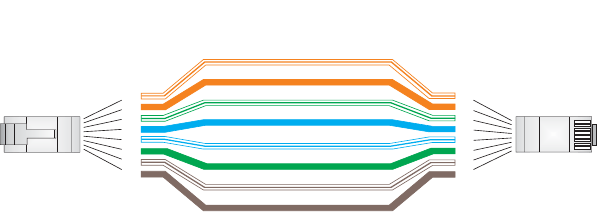
C-3
STRAIGHT-THROUGH WIRING
Because the 10/100 Mbps Input port on the power injector uses an MDI pin
configuration, you must use “straight-through” cable for network connections to
hubs or switches that only have MDI-X ports. However, if the device to which you
are connecting supports automatic MDI/MDI-X operation, you can use either
“straight-through” or “crossover” cable.
White/Orange Stripe
Orange
White/Green Stripe
Green
1
2
3
4
5
6
7
8
1
2
3
4
5
6
7
8
EIA/TIA 568B RJ-45 Wiring Standard
10/100BASE-TX Straight-through Cable
End A End B
Blue
White/Blue Stripe
Brown
White/Brown Stripe

C-4
CROSSOVER WIRING
Because the 10/100 Mbps port on the power injector uses an MDI pin
configuration, you must use “crossover” cable for network connections to PCs,
servers or other end nodes that only have MDI ports. However, if the device to
which you are connecting supports automatic MDI/MDI-X operation, you can use
either “straight-through” or “crossover” cable.
White/Orange Stripe
Orange
White/Green Stripe
1
2
3
4
5
6
7
8
1
2
3
4
5
6
7
8
EIA/TIA 568B RJ-45 Wiring Standard
10/100BASE-TX Crossover Cable
End A End B
Green
Blue
White/Blue Stripe
Brown
White/Brown Stripe

C-5
8-PIN DIN CONNECTOR PINOUT
The Ethernet cable from the power injector connects to an 8-pin DIN connector
on the wireless bridge. This connector is described in the following figure and
table.
8-Pin DIN Ethernet Port Pinout
Pin Signal Name
1Transmit Data plus (TD+)
2Transmit Data minus (TD-)
3Receive Data plus (RD+)
4+48 VDC power
5+48 VDC power
6Receive Data minus (RD-)
7Return power
8Return power
Note: The “+” and “-” signs represent the polarity of the wires that make up each wire pair.
1
7
2
3
4
5
8
6

C-6
8-PIN DIN TO RJ-45 CABLE WIRING
To construct an extended Ethernet cable to connect from the power injector’s
RJ-45 Output port to the wireless bridge’s 8-pin DIN connector, follow the wiring
diagram below. Use Category 5 or better UTP or STP cable, maximum length 100
m (328 ft), and be sure to connect all four wire pairs.
NOTE: To construct a reliable Ethernet cable, always use the proper tools or ask
a professional cable supplier to construct the cable.
White/Orange Stripe
Orange
White/Green Stripe
Green
1
2
3
4
5
6
7
8
1
2
3
4
5
6
7
8
8-Pin DIN
Female RJ-45
1
7
2
3
4
5
8
6
White/Blue Stripe
White/Brown Stripe
Brown
Blue
8-Pin DIN Female
Front View

D-1
DSPECIFICATIONS
GENERAL SPECIFICATIONS
MAXIMUM CHANNELS
802.11a:
US & Canada: 13 (normal mode), 5 (turbo mode)
Japan: 4 (normal mode), 1 (turbo mode)
ETSI: 11 channels (normal mode), 4 (turbo mode)
Taiwan: 8 (normal mode), 3 (turbo mode)
802.11b/g:
FCC/IC: 1-11
ETSI: 1-13
France: 10-13
MKK: 1-14
Taiwan: 1-11
MAXIMUM CLIENTS
64 per VAP interface
OPERATING RANGE
See “Operating Range” on page 6
DATA RATE
802.11a:
Normal Mode: 6, 9, 12, 18, 24, 36, 48, 54 Mbps per channel
Turbo Mode: 12, 18, 24, 36, 48, 54, 96, 108 Mbps per channel
802.11g: 6, 9, 11, 12, 18, 24, 36, 48, 54 Mbps per channel
802.11b: 1, 2, 5.5, 11 Mbps per channel

D-2
MODULATION TYPE
802.11a: BPSK, QPSK, 16-QAM, 64-QAM
802.11g: CCK, BPSK, QPSK, OFDM
802.11b: CCK, BPSK, QPSK
NETWORK CONFIGURATION
Bridge Mode:
Point-to-point and point-to-multipoint
Access Point Mode:
Infrastructure
OPERATING FREQUENCY
802.11a:
5.15 ~ 5.25 GHz (lower band) US/Canada, Japan
5.25 ~ 5.35 GHz (middle band) US/Canada
5.725 ~ 5.825 GHz (upper band) US/Canada
5.50~ 5.70 GHz Europe
5.25 ~ 5.35 GHz (middle band) Taiwan
5.725 ~ 5.825 GHz (high band) Taiwan
802.11b:
2.4 ~ 2.4835 GHz (US, Canada, ETSI)
2.4 ~ 2.497 GHz (Japan)
2.400 ~ 2.4835 GHz (Taiwan)
POWER INJECTOR
Input: 100-240 VAC, 47-63 Hz, 1.5 A
Output: 48 VDC, 1.2 A
Bridge Power (DC)
Input voltage: 48 volts, 1.2 A, 30 watts maximum
PHYSICAL SIZE
19.8 x 19.8 x 6.33 cm (7.8 x 7.8 x 2.49 in)
POE (DC)
Input voltage: 48 volts, 0.2 A, 12.96 watts
NOTE: Power can also be provided to the access point through the Ethernet port
based on IEEE 802.3af Power over Ethernet (PoE) specifications. When both PoE
is provided and the adapter is plugged in, AC power will be turned off.
D-3
WEIGHT
4.8kg (10.58 lbs)
LED INDICATORS
PWR (Power), Link (Ethernet Link/Activity), 11a and 11g (Wireless Link/Activity)
NETWORK MANAGEMENT
Web-browser, RS232 console, Telnet, SSH, SNMP
TEMPERATURE
Operating: 0 to 50 °C (32 to 122 °F)
Storage: 0 to 70 °C (32 to 158 °F)
HUMIDITY
15% to 95% (non-condensing)
COMPLIANCES
FCC Class B (US)
ICES-003 (Canada)
RTTED 1999/5/EC
VCCI (Japan)
RCR STD-33A
RADIO SIGNAL CERTIFICATION
FCC Part 15C 15.247, 15.207 (2.4 GHz)
FCC part 15E 15.407 (5 GHz)
RSS-210 (Canada)
EN 301.893, EN 300.328, EN 301.489-1, EN 301.489-17
MPT RCR std.33 (D33 1~13 Channel, T66 Channel 14)
SAFETY
cCSAus(CSA 22.2 No. 60950-1 & UL60950-1)
EN60950-1 (TÜV/GS), IEC60950-1 (CB)
STANDARDS
IEEE 802.3 10BASE-T, IEEE 802.3u 100BASE-TX,
IEEE 802.11a, b, g

D-4
SENSITIVITY
IEEE 802.11a Sensitivity (GHz - dBm)
Modulation/Rates 5.15-5.250 5.25-5.350 5.50-5.700 5.725-5.825
BPSK (6 Mbps) -88 -88 -88 -88
BPSK (9 Mbps) -87 -87 -87 -87
QPSK (12 Mbps) -86 -86 -86 -86
QPSK (18 Mbps) -84 -84 -84 -84
16 QAM (24 Mbps) -82 -81 -81 -81
16 QAM (36 Mbps) -80 -79 -78 -78
64 QAM (48 Mbps) -73 -73 -73 -73
64QAM(54 Mbps) -70 -70 -69 -67
IEEE 802.11g
Data Rate Sensitivity (dBm)
6 Mbps -88
9 Mbps -87
12 Mbps -86
17 Mbps -85
24 Mbps -81
36 Mbps -77
48 Mbps -72
54 Mbps -70
IEEE 802.11b
Data Rate Sensitivity (dBm)
1 Mbps -93
2 Mbps -90
5.5 Mbps -90
11 Mbps -87

D-5
TRANSMIT POWER
IEEE 802.11a Maximum Output Power (GHz - dBm)
Data Rate 5.15-5.250 5.25-5.350 5.50-5.700 5.725-5.825
6 Mbps 17 17 17 17
9 Mbps 17 17 17 17
12 Mbps 17 17 17 17
8 Mbps 17 17 17 17
24 Mbps 17 17 17 17
36 Mbps 17 17 17 17
48 Mbps 17 17 17 17
54 Mbps 12 17 17 16
IEEE 802.11g Maximum Output Power (GHz - dBm)
Data Rate 2.412 2.417~2.467 2.472
6 Mbps 20 20 18
9 Mbps 20 20 18
12 Mbps 20 20 18
18 Mbps 20 20 18
24 Mbps 20 20 18
36 Mbps 18 19 17
48 Mbps 17 16 15
54 Mbps 15 14 13
IEEE 802.11b Maximum Output Power (GHz - dBm)
Data Rate 2.412 2.417~2.467 2.472
1 Mbps 15 16 15
2 Mbps 15 16 15
5.5 Mbps 15 16 15
11 Mbps 15 16 15

D-6
OPERATING RANGE
Important Notice
Maximum distances posted below are actual tested distance thresholds.
However, there are many variables such as barrier
composition and construction
and local environmental interference
that may impact your actual distances and
cause you to experience
distance thresholds far lower than those posted below.
802.11a Wireless Distance Table
Speed and Distance Ranges
Environment 108
Mbps 72
Mbps 54
Mbps 48
Mbps 36
Mbps 24
Mbps 18
Mbps 12
Mbps 9
Mbps 6
Mbps
Outdoors130 m
99 ft
40 m
131 ft
85 m
279 ft
250 m
820 ft
310 m
1016 ft
400 m
1311 ft
445 m
1459 ft
455 m
1492 ft
465 m
1525 ft
510 m
1672 ft
Indoors215 m
49.5 ft 20 m
66 ft 25 m
82 ft 35 m
115 ft 40 m
131 ft
45 m
148 ft
50 m
164 ft
55 m
180 ft
66 m
216 ft
70 m
230 ft
802.11g Wireless Distance Table
Speed and Distance Ranges
Environment 54
Mbp
s
48
Mbps 36
Mbps 24
Mbps 18
Mbps 12
Mbps 11
Mbps 9
Mbps 6
Mbps 5
Mbps 2
Mbps 1
Mbps
Outdoors182 m
269
ft
100
m
328
ft
300
m
984
ft
330 m
1082
ft
350 m
1148
ft
450 m
1475
ft
470 m
1541
ft
485 m
1590
ft
495 m
1623
ft
510 m
1672
ft
520 m
1705
ft
525 m
1722
ft
Indoors220 m
66 ft 25 m
82 ft 35 m
115
ft
43 m
141 ft 50 m
164 ft 57 m
187 ft
66 m
216 ft
71 m
233 ft
80 m
262 ft
85 m
279 ft
90 m
295 ft
93 m
305 ft
802.11b Wireless Distance Table
Speed and Distance Ranges
Environment 11 Mbps 5.5 Mbps 2 Mbps 1 Mbps
Outdoors1300 m
984 ft 465 m
1525 ft 500 m
1639 ft 515 m
1689 ft
Indoors260 m
197 ft 70 m
230 ft 83 m
272 ft 85 m
279 ft

D-7
NOTE: Outdoor Environment: A line-of-sight environment with no interference
or obstruction between the access point and clients.
NOTE: Indoor Environment: A typical office or home environment with floor to
ceiling obstructions between the access point and clients.
D-8

Glossary-1
GLOSSARY
10BASE-T
IEEE 802.3 specification for 10 Mbps Ethernet over two pairs of Category 3 or better UTP cable.
100BASE-TX
IEEE 802.3u specification for 100 Mbps Fast Ethernet over two pairs of Category 5 or better UTP
cable.
Access Point
An internetworking device that seamlessly connects wired and wireless networks. Access points
attached to a wired network, support the creation of multiple radio cells that enable roaming
throughout a facility.
Ad Hoc
A group of computers connected as an independent wireless network, without an access point.
Advanced Encryption Standard (AES)
An encryption algorithm that implements symmetric key cryptography. AES provides very strong
encryption using a completely different ciphering algorithm to TKIP and WEP.
Authentication
The process to verify the identity of a client requesting network access. IEEE 802.11 specifies two
forms of authentication: open system and shared key.
Backbone
The core infrastructure of a network. The portion of the network that transports information from
one central location to another central location where it is unloaded onto a local system.
Basic Service Set (BSS)
A set of 802.11-compliant stations and an access point that operate as a fully-connected wireless
network.
Beacon
A signal periodically transmitted from the access point that is used to identify the service set, and
to maintain contact with wireless clients.
Glossary-2
Broadcast Key
Broadcast keys are sent to stations using 802.1X dynamic keying. Dynamic broadcast key
rotation is often used to allow the access point to generate a random group key and periodically
update all key-management capable wireless clients.
CSMA/CA
Carrier Sense Multiple Access with Collision Avoidance.
Dynamic Host Configuration Protocol (DHCP)
Provides a framework for passing configuration information to hosts on a TCP/IP network. DHCP
is based on the Bootstrap Protocol (BOOTP), adding the capability of automatic allocation of
reusable network addresses and additional configuration options.
Encryption
Data passing between the access point and clients can use encryption to protect from
interception and evesdropping.
Extended Service Set (ESS)
More than one wireless cell can be configured with the same Service Set Identifier to allow mobile
users can roam between different cells with the Extended Service Set.
Extensible Authentication Protocol (EAP)
An authentication protocol used to authenticate network clients. EAP is combined with IEEE
802.1X port authentication and a RADIUS authentication server to provide “mutual
authentication” between a client, the access point, and the a RADIUS server
Ethernet
A popular local area data communications network, which accepts transmission from computers
and terminals.
File Transfer Protocol (FTP)
A TCP/IP protocol used for file transfer.
Hypertext Transfer Protocol (HTTP)
HTTP is a standard used to transmit and receive all data over the World Wide Web.
IEEE 802.11a
A wireless standard that supports high-speed communications in the 5 GHz band using
Orthogonal Frequency Division Multiplexing (OFDM). The standard supports data rates of 6, 12,
24, and 54 Mbps.
Glossary-3
IEEE 802.11b
A wireless standard that supports wireless communications in the 2.4 GHz band using Direct
Sequence Spread Spectrum (DSSS). The standard provides for data rates of 1, 2, 5.5, and 11
Mbps.
IEEE 802.11g
A wireless standard that supports wireless communications in the 2.4 GHz band using using
Orthogonal Frequency Division Multiplexing (OFDM). The standard provides for data rates of 6,
9, 11, 12, 18, 24, 36, 48, 54 Mbps. IEEE 802.11g is also backward compatible with IEEE 802.11b.
IEEE 802.1X
Port Authentication controls access to the switch ports by requiring users to first enter a user ID
and password for authentication.
Infrastructure
An integrated wireless and wired LAN is called an infrastructure configuration.
Inter Access Point Protocol (IAPP)
A protocol that specifies the wireless signaling required to ensure the successful handover of
wireless clients roaming between different 802.11f-compliant access points.
Local Area Network (LAN)
A group of interconnected computer and support devices.
MAC Address
The physical layer address used to uniquely identify network nodes.
Network Time Protocol (NTP)
NTP provides the mechanisms to synchronize time across the network. The time servers operate
in a hierarchical-master-slave configuration in order to synchronize local clocks within the subnet
and to national time standards via wire or radio.
Open System
A security option which broadcasts a beacon signal including the access point’s configured SSID.
Wireless clients can read the SSID from the beacon, and automatically reset their SSID to allow
immediate connection to the nearest access point.
Orthogonal Frequency Division Multiplexing (ODFM)
OFDM/ allows multiple users to transmit in an allocated band by dividing the bandwidth into many
narrow bandwidth carriers.
Power over Ethernet (PoE)
A specification for providing both power and data to low-power network devices using a single
Category 5 Ethernet cable. PoE provides greater flexibility in the locating of access point’s and
network devices, and significantly decreased installation costs.
Glossary-4
RADIUS
A logon authentication protocol that uses software running on a central server to control access to
the network.
Roaming
A wireless LAN mobile user moves around an ESS and maintains a continuous connection to the
infrastructure network.
RTS Threshold
Transmitters contending for the medium may not be aware of each other. RTS/CTS mechanism
can solve this “Hidden Node Problem.” If the packet size is smaller than the preset RTS
Threshold size, the RTS/CTS mechanism will NOT be enabled.
Service Set Identifier (SSID)
An identifier that is attached to packets sent over the wireless LAN and functions as a password
for joining a particular radio cell; i.e., Basic Service Set (BSS).
Session Key
Session keys are unique to each client, and are used to authenticate a client connection, and
correlate traffic passing between a specific client and the access point.
Shared Key
A shared key can be used to authenticate each client attached to a wireless network. Shared Key
authentication must be used along with the 802.11 Wireless Equivalent Privacy algorithm.
Simple Network Management Protocol (SNMP)
The application protocol in the Internet suite of protocols which offers network management
services.
Simple Network Time Protocol (SNTP)
SNTP allows a device to set its internal clock based on periodic updates from a Network Time
Protocol (NTP) server. Updates can be requested from a specific NTP server, or can be received
via broadcasts sent by NTP servers.
Temporal Key Integrity Protocol (TKIP)
A data encryption method designed as a replacement for WEP. TKIP avoids the problems of
WEP static keys by dynamically changing data encryption keys.
Trivial File Transfer Protocol (TFTP)
A TCP/IP protocol commonly used for software downloads.
Virtual Access Point (VAP)
Virtual AP technology multiplies the number of Access Points present within the RF footprint of a
single physical access device. With Virtual AP technology, WLAN users within the device’s
footprint can associate with what appears to be different access points and their associated
Glossary-5
network services. All the services are delivered using a single radio channel, enabling Virtual AP
technology to optimize the use of limited WLAN radio spectrum.
Virtual LAN (VLAN)
A Virtual LAN is a collection of network nodes that share the same collision domain regardless of
their physical location or connection point in the network. A VLAN serves as a logical workgroup
with no physical barriers, and allows users to share information and resources as though located
on the same LAN.
Wi-Fi Protected Access
WPA employs 802.1X as its basic framework for user authentication and dynamic key
management to provide an enhanced security solution for 802.11 wireless networks.
Wired Equivalent Privacy (WEP)
WEP is based on the use of security keys and the popular RC4 encryption algorithm. Wireless
devices without a valid WEP key will be excluded from network traffic.
WPA Pre-shared Key (PSK)
PSK can be used for small office networks that may not have the resources to configure and
maintain a RADIUS server, WPA provides a simple operating mode that uses just a pre-shared
password for network access.
Glossary-6

1
Numbers
802.11g 94
A
Advanced Encryption Standard See AES
AES 60
configuring 50
AES, configuring 48
authentication 11
cipher suite 119
closed system 107
configuring 11
MAC address 12, 70, 71
type 53, 107
web redirect 20
B
Basic Service Set See BSS
beacon
interval 43, 102
rate 43, 103
BOOTP 89, 90
BPDU 36
BSS 2
C
cable
assignments 1
crossover 4
straight-through 3
channel 43, 98
channels, maximum 1
Clear To Send See CTS
CLI 1
command modes 4
clients, maximum 1
closed system 107
command line interface See CLI
community name, configuring 20, 41
community string 21, 41
configuration settings, saving or restoring 25, 56
configuration, initial setup 1
console port
required settings 1
country code
configuring 3, 12
crossover cable 4
CSMA/CA 1
CTS 44, 105
D
data rate
maximum distances 6
data rate, options 1
default settings 7
device status, displaying 63, 23
DHCP 5, 6, 89, 90
distances, maximum 6
DNS 6, 89
Domain Name Server See DNS
downloading software 24, 56
DTIM 43, 103
E
EAP 59
encryption 48, 53, 54, 59
Ethernet
port 4
event logs 67, 32
Extensible Authentication Protocol See EAP
F
factory defaults
restoring 25, 10
fast forwarding, STP 38
filter 18, 70
address 11, 70
between wireless clients 19, 74
local bridge 19, 74
local or remote 11, 72
management access 19, 74
protocol types 19, 75
VLANs 18, 132
firmware
displaying version 24
upgrading 24, 25, 56
fragmentation 104

2
G
gateway address 2, 6, 1, 89
H
hardware version, displaying 24
HTTP, secure server 19
HTTPS 19
I
IAPP 131
IEEE 802.11a 1, 41, 94
configuring interface 42, 94
maximum data rate 43, 97
radio channel 43, 98
IEEE 802.11b 41
IEEE 802.11f 131
IEEE 802.11g 41
configuring interface 46, 94
maximum data rate 47, 97
radio channel 46, 98
IEEE 802.1x 59, 65, 70
configuring 11, 12, 65
initial setup 1
installation 1
IP address
BOOTP/DHCP 89, 90
configuring 2, 5, 89, 90
L
log
messages 28, 67, 29
server 27, 29
login
CLI 1
web 3
logon authentication
RADIUS client 14, 59
M
MAC address, authentication 12, 70, 71
maximum data rate 43, 47, 97
802.11a interface 43, 97
802.11g interface 47, 97
maximum distances 6
MDI, RJ-45 pin configuration 4
multicast cipher 61
N
network topologies
infrastructure 2
infrastructure for roaming 3
O
OFDM 1
open system 53, 107
operating frequency 2
P
package checklist 2
password
configuring 23, 15
management 23, 15
PoE 8, 11
specifications 2
port priority
STA 86
Power over Ethernet See PoE
power supply, specifications 2
PSK 60
R
radio channel
802.11a interface 43, 98
802.11g interface 46, 98
RADIUS 7, 59
RADIUS, logon authentication 14, 59
Remote Authentication Dial-in User Service See
RADIUS
Request to Send See RTS
reset 25, 10
reset button 4, 25
resetting the access point 25, 10
restarting the system 25, 10
RJ-45 port
configuring duplex mode 91
configuring speed 91
RSSI BNC 5
RTS
threshold 44, 104
S
Secure Socket Layer See SSL
security, options 53

3
session key 13, 67
shared key 49, 56, 121
Simple Network Management Protocol See SNMP
Simple Network Time Protocol See SNTP
SNMP 20, 40
community name 20, 41
community string 41
enabling traps 21, 42
trap destination 21, 43
trap manager 21, 43
SNTP 29, 34
enabling client 29, 34
server 29, 34
software
displaying version 24, 63, 24
downloading 25, 56
SSID 107
SSL 19
STA
interface settings 86 to ??
path cost 86
port priority 86
startup files, setting 55
station status 65, 112
status
displaying device status 63, 23
displaying station status 65, 112
STP
fast forwarding 38
straight-through cable 3
system clock, setting 29, 35
system log
enabling 27, 29
server 27, 29
system software, downloading from server 24, 56
T
Tel ne t
for managenet access 1
Temporal Key Integrity Protocol See TKIP
time zone 30, 36
TKIP 59
transmit power, configuring 43, 98
trap destination 21, 43
trap manager 21, 43
U
upgrading software 24, 56
user name, manager 23, 15
user password 23, 15
V
VLAN
configuration 18, 132
native ID 18
W
WEP 48, 54
configuring 48, 54
shared key 49, 56, 121
Wi-Fi Multimedia See WMM
Wi-Fi Protected Access See WPA
Wired Equivalent Protection See WEP
WPA 59
authentication over 802.11x 61
pre-shared key 61, 125
WPA, pre-shared key See PSK
Users Manual2

System Logging Commands
7-31
7
Command Usage
Messages sent include the selected level down to Emergency level.
Example
logging facility-type
This command sets the facility type for remote logging of syslog messages.
Syntax
logging facility-type <type>
type - A number that indicates the facility used by the syslog server to
dispatch log messages to an appropriate service. (Range: 16-23)
Default Setting
16
Command Mode
Global Configuration
Level Argument Description
Emergency System unusable
Alert Immediate action needed
Critical Critical conditions (e.g., memory allocation, or free memory error - resource
exhausted)
Error Error conditions (e.g., invalid input, default used)
Warning Warning conditions (e.g., return false, unexpected return)
Notice Normal but significant condition, such as cold start
Informational Informational messages only
Debug Debugging messages
Enterprise AP(config)#logging level alert
Enterprise AP(config)#

Command Line Interface
7-32
7
Command Usage
The command specifies the facility type tag sent in syslog messages. (See
RFC 3164.) This type has no effect on the kind of messages reported by the
bridge. However, it may be used by the syslog server to sort messages or to
store messages in the corresponding database.
Example
logging clear
This command clears all log messages stored in the bridge’s memory.
Syntax
logging clear
Command Mode
Global Configuration
Example
show logging
This command displays the logging configuration.
Syntax
show logging
Command Mode
Exec
Example
Enterprise AP(config)#logging facility 19
Enterprise AP(config)#
Enterprise AP(config)#logging clear
Enterprise AP(config)#
Enterprise AP#show logging
Logging Information
============================================
Syslog State : Enabled
Logging Console State : Enabled
Logging Level : Alert
Logging Facility Type : 16
Servers
1: 192.168.1.19, UDP Port: 514, State: Enabled
2: 0.0.0.0, UDP Port: 514, State: Disabled
3: 0.0.0.0, UDP Port: 514, State: Disabled
4: 0.0.0.0, UDP Port: 514, State: Disabled
=============================================
Enterprise AP#

System Clock Commands
7-33
7
show event-log
This command displays log messages stored in the bridge’s memory.
Syntax
show event-log
Command Mode
Exec
Example
System Clock Commands
These commands are used to configure SNTP and system clock settings on the
bridge.
Enterprise AP#show event-log
Mar 09 11:57:55 Information: 802.11g:11g Radio Interface Enabled
Mar 09 11:57:55 Information: 802.11g:Radio channel updated to 8
Mar 09 11:57:34 Information: 802.11g:11g Radio Interface Enabled
Mar 09 11:57:18 Information: 802.11g:11g Radio Interface Enabled
Mar 09 11:56:35 Information: 802.11a:11a Radio Interface Enabled
Mar 09 11:55:52 Information: SSH task: Set SSH server port to 22
Mar 09 11:55:52 Information: SSH task: Enable SSH server.
Mar 09 11:55:52 Information: Enable Telnet.
Mar 09 11:55:40 Information: 802.11a:11a Radio Interface Disabled
Mar 09 11:55:40 Information: 802.11a:Transmit Power set to QUARTER
Press <n> next. <p> previous. <a> abort. <y> continue to end :
Enterprise AP#configure
Enter configuration commands, one per line. End with CTRL/Z
Enterprise AP(config)#logging clear
Table7-7. System Clock Commands
Command Function Mode Page
sntp-server ip Specifies one or more time servers GC 7-34
sntp-server enable Accepts time from the specified time servers GC 7-34
sntp-server date-time Manually sets the system date and time GC 7-35
sntp-server
daylight-saving Sets the start and end dates for daylight savings time GC 7-36
sntp-server timezone Sets the time zone for the bridge’s internal clock GC 7-36
show sntp Shows current SNTP configuration settings Exec 7-37

Command Line Interface
7-34
7
sntp-server ip
This command sets the IP address of the servers to which SNTP time requests are
issued. Use the this command with no arguments to clear all time servers from the
current list.
Syntax
sntp-server ip <1 | 2> <ip>
•1 - First time server.
•2 - Second time server.
•ip - IP address of an time server (NTP or SNTP).
Default Setting
137.92.140.80
192.43.244.18
Command Mode
Global Configuration
Command Usage
When SNTP client mode is enabled using the sntp-server enable command,
the sntp-server ip command specifies the time servers from which the bridge
polls for time updates. The bridge will poll the time servers in the order
specified until a response is received.
Example
Related Commands
sntp-server enable (7-34)
show sntp (7-37)
sntp-server enable
This command enables SNTP client requests for time synchronization with NTP or
SNTP time servers specified by the sntp-server ip command. Use the no form to
disable SNTP client requests.
Syntax
sntp-server enable
no sntp-server enable
Default Setting
Enabled
Enterprise AP(config)#sntp-server ip 10.1.0.19
Enterprise AP#

System Clock Commands
7-35
7
Command Mode
Global Configuration
Command Usage
The time acquired from time servers is used to record accurate dates and
times for log events. Without SNTP, the bridge only records the time starting
from the factory default set at the last bootup (i.e., 00:14:00, January 1, 1970).
Example
Related Commands
sntp-server ip (7-34)
show sntp (7-37)
sntp-server date-time
This command sets the system clock.
Default Setting
00:14:00, January 1, 1970
Command Mode
Global Configuration
Example
This example sets the system clock to 17:37 June 19, 2003.
Related Commands
sntp-server enable (7-34)
Enterprise AP(config)#sntp-server enable
Enterprise AP(config)#
Enterprise AP#sntp-server date-time
Enter Year<1970-2100>: 2003
Enter Month<1-12>: 6
Enter Day<1-31>: 19
Enter Hour<0-23>: 17
Enter Min<0-59>: 37
Enterprise AP#

Command Line Interface
7-36
7
sntp-server daylight-saving
This command sets the start and end dates for daylight savings time. Use the no
form to disable daylight savings time.
Syntax
sntp-server daylight-saving
no sntp-server daylight-saving
Default Setting
Disabled
Command Mode
Global Configuration
Command Usage
The command sets the system clock back one hour during the specified
period.
Example
This sets daylight savings time to be used from July 1st to September 1st.
sntp-server timezone
This command sets the time zone for the bridge’s internal clock.
Syntax
sntp-server timezone <hours>
hours - Number of hours before/after UTC.
(Range: -12 to +12 hours)
Default Setting
-5 (BOGOTA, EASTERN, INDIANA)
Command Mode
Global Configuration
Enterprise AP(config)#sntp-server daylight-saving
Enter Daylight saving from which month<1-12>: 6
and which day<1-31>: 1
Enter Daylight saving end to which month<1-12>: 9
and which day<1-31>: 1
Enterprise AP(config)#

System Clock Commands
7-37
7
Command Usage
This command sets the local time zone relative to the Coordinated Universal
Time (UTC, formerly Greenwich Mean Time or GMT), based on the earth’s
prime meridian, zero degrees longitude. To display a time corresponding to
your local time, you must indicate the number of hours and minutes your time
zone is east (before) or west (after) of UTC.
Example
show sntp
This command displays the current time and configuration settings for the SNTP
client.
Command Mode
Exec
Example
Enterprise AP(config)#sntp-server timezone +8
Enterprise AP(config)#
Enterprise AP#show sntp
SNTP Information
=========================================================
Service State : Enabled
SNTP (server 1) IP : 137.92.140.80
SNTP (server 2) IP : 192.43.244.18
Current Time : 08 : 04, Jun 20th, 2003
Time Zone : +8 (TAIPEI, BEIJING)
Daylight Saving : Enabled, from Jun, 1st to Sep, 1st
=========================================================
Enterprise AP#

Command Line Interface
7-38
7
DHCP Relay Commands
Dynamic Host Configuration Protocol (DHCP) can dynamically allocate an IP
address and other configuration information to network clients that broadcast a
request. To receive the broadcast request, the DHCP server would normally have to
be on the same subnet as the client. However, when the bridge’s DHCP relay agent
is enabled, received client requests can be forwarded directly by the bridge to a
known DHCP server on another subnet. Responses from the DHCP server are
returned to the bridge, which then broadcasts them back to clients.
dhcp-relay enable
This command enables the bridge’s DHCP relay agent. Use the no form to disable
the agent.
Syntax
[no] dhcp-relay enable
Default Setting
Disabled
Command Mode
Global Configuration
Command Usage
• For the DHCP relay agent to function, the primary DHCP server must be
configured using the dhcp-relay primary command. A secondary DHCP
server does not need to be configured, but it is recommended.
• If there is no response from the primary DHCP server, and a secondary
server has been configured, the agent will then attempt to send DHCP
requests to the secondary server.
Example
Table 7-8. DHCP Relay Commands
Command Function Mode Page
dhcp-relay enable Enables the DHCP relay agent GC 7-38
dhcp-relay Sets the primary and secondary DHCP server
address GC 7-39
show dhcp-relay Shows current DHCP relay configuration settings Exec 7-39
Enterprise AP(config)#dhcp-relay enable
Enterprise AP(config)#

DHCP Relay Commands
7-39
7
dhcp-relay
This command configures the primary and secondary DHCP server addresses.
Syntax
dhcp-relay <primary | secondary> <ip_address>
•primary - The primary DHCP server.
•secondary - The secondary DHCP server.
•ip_address - IP address of the server.
Default Setting
Primary and secondary: 0.0.0.0
Command Mode
Global Configuration
Example
show dhcp-relay
This command displays the current DHCP relay configuration.
Command Mode
Exec
Example
Enterprise AP(config)#dhcp-relay primary 192.168.1.10
Enterprise AP(config)#
Enterprise AP#show dhcp-relay
DHCP Relay : ENABLED
Primary DHCP Server : 192.168.1.10
Secondary DHCP Server : 0.0.0.0
Enterprise AP#

Command Line Interface
7-40
7
SNMP Commands
Controls access to this bridge from management stations using the Simple Network
Management Protocol (SNMP), as well as the hosts that will receive trap messages.
Table7-9. SNMP Commands
Command Function Mode Page
snmp-server community Sets up the community access string to permit access
to SNMP commands GC 7-41
snmp-server contact Sets the system contact string GC 7-41
snmp-server location Sets the system location string GC 7-42
snmp-server enable server Enables SNMP service and traps GC 7-42
snmp-server host Specifies the recipient of an SNMP notification
operation GC 7-43
snmp-server trap Enables specific SNMP notifications GC 7-44
snmp-server engine id Sets the engine ID for SNMP v3 GC 7-45
snmp-server user Sets the name of the SNMP v3 user GC 7-46
snmp-server targets Configures SNMP v3 notification targets GC 7-48
snmp-server filter Configures SNMP v3 notification filters GC 7-49
snmp-server
filter-assignments Assigns SNMP v3 notification filters to targets GC 7-50
show snmp groups Displays the pre-defined SNMP v3 groups Exec 7-50
show snmp users Displays SNMP v3 user settings Exec 7-51
show snmp
group-assignments Displays the assignment of users to SNMP v3 groups Exec 7-51
show snmp target Displays the SNMP v3 notification targets Exec 7-52
show snmp filter Displays the SNMP v3 notification filters Exec 7-52
show snmp
filter-assignments Displays the SNMP v3 notification filter assignments Exec 7-53
show snmp Displays the status of SNMP communications Exec 7-54

SNMP Commands
7-41
7
snmp-server community
This command defines the community access string for the Simple Network
Management Protocol. Use the no form to remove the specified community string.
Syntax
snmp-server community string [ro | rw]
no snmp-server community string
•string - Community string that acts like a password and permits access to
the SNMP protocol. (Maximum length: 23 characters, case sensitive)
•ro - Specifies read-only access. Authorized management stations are only
able to retrieve MIB objects.
•rw - Specifies read/write access. Authorized management stations are able
to both retrieve and modify MIB objects.
Default Setting
• public - Read-only access. Authorized management stations are only able
to retrieve MIB objects.
• private - Read/write access. Authorized management stations are able to
both retrieve and modify MIB objects.
Command Mode
Global Configuration
Command Usage
If you enter a community string without the ro or rw option, the default is read
only.
Example
snmp-server contact
This command sets the system contact string. Use the no form to remove the
system contact information.
Syntax
snmp-server contact string
no snmp-server contact
string - String that describes the system contact. (Maximum length: 255
characters)
Default Setting
None
Enterprise AP(config)#snmp-server community alpha rw
Enterprise AP(config)#

Command Line Interface
7-42
7
Command Mode
Global Configuration
Example
Related Commands
snmp-server location (7-42)
snmp-server location
This command sets the system location string. Use the no form to remove the
location string.
Syntax
snmp-server location <text>
no snmp-server location
text - String that describes the system location.
(Maximum length: 255 characters)
Default Setting
None
Command Mode
Global Configuration
Example
Related Commands
snmp-server contact (7-41)
snmp-server enable server
This command enables SNMP management access and also enables this device to
send SNMP traps (i.e., notifications). Use the no form to disable SNMP service and
trap messages.
Syntax
snmp-server enable server
no snmp-server enable server
Default Setting
Enabled
Enterprise AP(config)#snmp-server contact Paul
Enterprise AP(config)#
Enterprise AP(config)#snmp-server location WC-19
Enterprise AP(config)#

SNMP Commands
7-43
7
Command Mode
Global Configuration
Command Usage
• This command enables both authentication failure notifications and
link-up-down notifications.
•The snmp-server host command specifies the host device that will receive
SNMP notifications.
Example
Related Commands
snmp-server host (7-43)
snmp-server host
This command specifies the recipient of an SNMP notification. Use the no form to
remove the specified host.
Syntax
snmp-server host <1 | 2 | 3 | 4> <host_ip_address | host_name>
<community-string>
no snmp-server host
•1 - First SNMP host.
•2 - Second SNMP host.
•3 - Third SNMP host.
•4 - Fourth SNMP host.
•host_ip_address - IP of the host (the targeted recipient).
•host_name - Name of the host. (Range: 1-63 characters)
•community-string - Password-like community string sent with the
notification operation. Although you can set this string using the
snmp-server host command by itself, we recommend that you define this
string using the snmp-server community command prior to using the
snmp-server host command. (Maximum length: 23 characters)
Default Setting
Host Address: None
Community String: public
Command Mode
Global Configuration
Enterprise AP(config)#snmp-server enable server
Enterprise AP(config)#

Command Line Interface
7-44
7
Command Usage
The snmp-server host command is used in conjunction with the
snmp-server enable server command to enable SNMP notifications.
Example
Related Commands
snmp-server enable server (7-42)
snmp-server trap
This command enables the bridge to send specific SNMP traps (i.e., notifications).
Use the no form to disable specific trap messages.
Syntax
snmp-server trap <trap>
no snmp-server trap <trap>
•trap - One of the following SNMP trap messages:
-dot11InterfaceAGFail - The 802.11a or 802.11g interface has failed.
-dot11InterfaceBFail - The 802.11b interface has failed.
-dot11StationAssociation - A client station has successfully associated
with the bridge.
-dot11StationAuthentication - A client station has been successfully
authenticated.
-dot11StationReAssociation - A client station has successfully
re-associated with the bridge.
-dot11StationRequestFail - A client station has failed association,
re-association, or authentication.
-dot1xAuthFail - A 802.1X client station has failed RADIUS
authentication.
-dot1xAuthNotInitiated - A client station did not initiate 802.1X
authentication.
-dot1xAuthSuccess - A 802.1X client station has been successfully
authenticated by the RADIUS server.
-dot1xMacAddrAuthFail - A client station has failed MAC address
authentication with the RADIUS server.
-dot1xMacAddrAuthSuccess - A client station has successfully
authenticated its MAC address with the RADIUS server.
-iappContextDataSent - A client station’s Context Data has been sent to
another bridge with which the station has associated.
-iappStationRoamedFrom - A client station has roamed from another
bridge (identified by its IP address).
Enterprise AP(config)#snmp-server host 1 10.1.19.23 batman
Enterprise AP(config)#

SNMP Commands
7-45
7
-iappStationRoamedTo - A client station has roamed to another bridge
(identified by its IP address).
-localMacAddrAuthFail - A client station has failed authentication with
the local MAC address database on the bridge.
-localMacAddrAuthSuccess - A client station has successfully
authenticated its MAC address with the local database on the bridge.
-pppLogonFail - The bridge has failed to log onto the PPPoE server
using the configured user name and password.
-sntpServerFail - The bridge has failed to set the time from the
configured SNTP server.
-sysConfigFileVersionChanged - The bridge’s configuration file has
been changed.
-sysRadiusServerChanged - The bridge has changed from the primary
RADIUS server to the secondary, or from the secondary to the primary.
-sysSystemDown - The bridge is about to shutdown and reboot.
-sysSystemUp - The bridge is up and running.
Default Setting
All traps enabled
Command Mode
Global Configuration
Command Usage
This command is used in conjunction with the snmp-server host and
snmp-server enable server commands to enable SNMP notifications.
Example
snmp-server engine-id
This command is used for SNMP v3. It is used to uniquely identify the bridge among
all bridges in the network. Use the no form to delete the engine ID.
Syntax
snmp-server engine-id <engine-id>
no snmp-server engine-id
engine-id - Enter engine-id in hexadecimal (5-32 characters).
Default Setting
Enabled
Enterprise AP(config)#no snmp-server trap dot11StationAssociation
Enterprise AP(config)#

Command Line Interface
7-46
7
Command Mode
Global Configuration
Command Usage
• This command is used in conjunction with the snmp-server user command.
• Entering this command invalidates all engine IDs that have been previously
configured.
• If the engineID is deleted or changed, all SNMP users will be cleared. You
will need to reconfigure all existing users
Example
snmp-server user
This command configures the SNMP v3 users that are allowed to manage the
bridge. Use the no form to delete an SNMP v3 user.
Syntax
snmp-server user <user-name>
user-name - A user-defined string for the SNMP user. (32 characters
maximum)
Default Setting
None
Command Mode
Global Configuration
Command Usage
• Up to 10 SNMPv3 users can be configured on the bridge.
• The SNMP engine ID is used to compute the authentication/privacy digests
from the pass phrase. You should therefore configure the engine ID with the
snmp-server engine-id command before using this configuration
command.
• The bridge enables SNMP v3 users to be assigned to three pre-defined
groups. Other groups cannot be defined. The available groups are:
- RO - A read-only group using no authentication and no data encryption.
Users in this group use no security, either authentication or encryption, in
SNMP messages they send to the agent. This is the same as SNMP v1
or SNMP v2c.
Enterprise AP(config)#snmp-server engine-id 1a:2b:3c:4d:00:ff
Enterprise AP(config)#

SNMP Commands
7-47
7
- RWAuth - A read/write group using authentication, but no data
encryption. Users in this group send SNMP messages that use an MD5
key/password for authentication, but not a DES key/password for
encryption.
- RWPriv - A read/write group using authentication and data encryption.
Users in this group send SNMP messages that use an MD5 key/
password for authentication and a DES key/password for encryption.
Both the MD5 and DES key/passwords must be defined.
• The command prompts for the following information to configure an SNMP
v3 user:
-user-name - A user-defined string for the SNMP user. (32 characters
maximum)
-group-name - The name of the SNMP group to which the user is
assigned (32 characters maximum). There are three pre-defined groups:
RO, RWAuth, or RWPriv.
-auth-proto - The authentication type used for user authentication: md5 or
none.
-auth-passphrase - The user password required when authentication is
used (8 – 32 characters).
-priv-proto - The encryption type used for SNMP data encryption: des or
none.
-priv-passphrase - The user password required when data encryption is
used (8 – 32 characters).
• Users must be assigned to groups that have the same security levels. If a
user who has “AuthPriv” security (uses authentication and encryption) is
assigned to a read-only (RO) group, the user will not be able to access the
database. An AuthPriv user must be assigned to the RWPriv group with the
AuthPriv security level.
• To configure a user for the RWAuth group, you must include the auth-proto
and auth-passphrase keywords.
• To configure a user for the RWPriv group, you must include the auth-proto,
auth-passphrase, priv-proto, and priv-passphrase keywords.
Example
Enterprise AP(config)#snmp-server user
User Name<1-32> :chris
Group Name<1-32> :RWPriv
Authtype(md5,<cr>none):md5
Passphrase<8-32>:a good secret
Privacy(des,<cr>none) :des
Passphrase<8-32>:a very good secret
Enterprise AP(config)#

Command Line Interface
7-48
7
snmp-server targets
This command configures SNMP v3 notification targets. Use the no form to delete
an SNMP v3 target.
Syntax
snmp-server targets <target-id> <ip-addr> <sec-name>
[version {3}] [udp-port {port-number}] [notification-type
{TRAP}]
no snmp-server targets <target-id>
•target-id - A user-defined name that identifies a receiver of SNMP
notifications. (Maximum length: 32 characters)
•ip-addr - Specifies the IP address of the management station to receive
notifications.
•sec-name - The defined SNMP v3 user name that is to receive
notifications.
•version - The SNMP version of notifications. Currently only version 3 is
supported in this command.
•udp-port - The UDP port that is used on the receiving management station
for notifications.
•notification-type - The type of notification that is sent. Currently only TRAP
is supported.
Default Setting
None
Command Mode
Global Configuration
Command Usage
• The bridge supports up to 10 SNMP v3 target IDs.
• The SNMP v3 user name that is specified in the target must first be
configured using the snmp-server user command.
Example
Enterprise AP(config)#snmp-server targets mytraps 192.168.1.33 chris
Enterprise AP(config)#

SNMP Commands
7-49
7
snmp-server filter
This command configures SNMP v3 notification filters. Use the no form to delete an
SNMP v3 filter or remove a subtree from a filter.
Syntax
snmp-server filter <filter-id> <include | exclude> <subtree>
[mask {mask}]
no snmp-server filter <filter-id> [subtree]
•filter-id - A user-defined name that identifies an SNMP v3 notification filter.
(Maximum length: 32 characters)
•include - Defines a filter type that includes objects in the MIB subtree.
•exclude - Defines a filter type that excludes objects in the MIB subtree.
•subtree - The part of the MIB subtree that is to be filtered.
•mask - An optional hexadecimal value bit mask to define objects in the MIB
subtree.
Default Setting
None
Command Mode
Global Configuration
Command Usage
• The bridge allows up to 10 notification filters to be created. Each filter can
be defined by up to 20 MIB subtree ID entries.
• Use the command more than once with the same filter ID to build a filter that
includes or excludes multiple MIB objects. Note that the filter entries are
applied in the sequence that they are defined.
• The MIB subtree must be defined in the form “.1.3.6.1” and always start with
a “.”.
• The mask is a hexadecimal value with each bit masking the corresponding
ID in the MIB subtree. A “1” in the mask indicates an exact match and a “0”
indicates a “wild card.” For example, a mask value of 0xFFBF provides a bit
mask “1111 1111 1011 1111.” If applied to the subtree
1.3.6.1.2.1.2.2.1.1.23, the zero corresponds to the 10th subtree ID. When
there are more subtree IDs than bits in the mask, the mask is padded with
ones.
Example
Enterprise AP(config)#snmp-server filter trapfilter include .1
Enterprise AP(config)#snmp-server filter trapfilter exclude
.1.3.6.1.2.1.2.2.1.1.23

Command Line Interface
7-50
7
snmp-server filter-assignments
This command assigns SNMP v3 notification filters to targets. Use the no form to
remove an SNMP v3 filter assignment.
Syntax
snmp-server filter-assignments <target-id> <filter-id>
no snmp-server filter-assignments <target-id>
•target-id - A user-defined name that identifies a receiver of SNMP
notifications. (Maximum length: 32 characters)
•filter-id - A user-defined name that identifies an SNMP v3 notification filter.
(Maximum length: 32 characters)
Default Setting
None
Command Mode
Global Configuration
Example
show snmp groups
This command displays the SNMP v3 pre-defined groups.
Syntax
show snmp groups
Command Mode
Exec
Enterprise AP(config)#snmp-server filter-assignments mytraps trapfilter
Enterprise AP(config)#exit
Enterprise AP#show snmp target
Host ID : mytraps
User : chris
IP Address : 192.168.1.33
UDP Port : 162
=============================
Enterprise AP#show snmp filter-assignments
HostID FilterID
mytraps trapfilter
Enterprise AP(config)#

SNMP Commands
7-51
7
Example
show snmp users
This command displays the SNMP v3 users and settings.
Syntax
show snmp users
Command Mode
Exec
Example
show snmp group-assignments
This command displays the SNMP v3 user group assignments.
Syntax
show snmp group-assignments
Command Mode
Exec
Enterprise AP#show snmp groups
GroupName :RO
SecurityModel :USM
SecurityLevel :NoAuthNoPriv
GroupName :RWAuth
SecurityModel :USM
SecurityLevel :AuthNoPriv
GroupName :RWPriv
SecurityModel :USM
SecurityLevel :AuthPriv
Enterprise AP#
Enterprise AP#show snmp users
=============================================
UserName :chris
GroupName :RWPriv
AuthType :MD5
Passphrase:****************
PrivType :DES
Passphrase:****************
=============================================
Enterprise AP#

Command Line Interface
7-52
7
Example
show snmp target
This command displays the SNMP v3 notification target settings.
Syntax
show snmp target
Command Mode
Exec
Example
show snmp filter
This command displays the SNMP v3 notification filter settings.
Syntax
show snmp filter [filter-id]
•filter-id - A user-defined name that identifies an SNMP v3 notification filter.
(Maximum length: 32 characters)
Command Mode
Exec
Example
Enterprise AP#show snmp group-assignments
GroupName :RWPriv
UserName :chris
Enterprise AP#
Enterprise AP#
Enterprise AP#show snmp target
Host ID : mytraps
User : chris
IP Address : 192.168.1.33
UDP Port : 162
=============================
Enterprise AP#
Enterprise AP#show snmp filter
Filter: trapfilter
Type: include
Subtree: iso.3.6.1.2.1.2.2.1
Type: exclude
Subtree: iso.3.6.1.2.1.2.2.1.1.23
=============================
Enterprise AP#

SNMP Commands
7-53
7
show snmp filter-assignments
This command displays the SNMP v3 notification filter assignments.
Syntax
show snmp filter-assignments
Command Mode
Exec
Example
Enterprise AP#show snmp filter-assignments
HostID FilterID
mytraps trapfilter
Enterprise AP#

Command Line Interface
7-54
7
show snmp
This command displays the SNMP configuration settings.
Command Mode
Exec
Example
Enterprise AP#show snmp
SNMP Information
==============================================
Service State : Enable
Community (ro) : *****
Community (rw) : *****
Location : WC-19
Contact : Paul
EngineId :80:00:07:e5:80:00:00:2e:62:00:00:00:18
EngineBoots:1
Trap Destinations:
1: 192.168.1.9, Community: *****, State: Enabled
2: 0.0.0.0, Community: *****, State: Disabled
3: 0.0.0.0, Community: *****, State: Disabled
4: 0.0.0.0, Community: *****, State: Disabled
dot11InterfaceAGFail Enabled dot11InterfaceBFail Enabled
dot11StationAssociation Enabled dot11StationAuthentication
Enabled
dot11StationReAssociation Enabled dot11StationRequestFail
Enabled
dot1xAuthFail Enabled dot1xAuthNotInitiated Enabled
dot1xAuthSuccess Enabled dot1xMacAddrAuthFail Enabled
dot1xMacAddrAuthSuccess Enabled iappContextDataSent
Enabled
iappStationRoamedFrom Enabled iappStationRoamedTo
Enabled
localMacAddrAuthFail Enabled localMacAddrAuthSuccess Enabled
pppLogonFail Enabled sntpServerFail Enabled
configFileVersionChanged Enabled radiusServerChanged
Enabled
systemDown Enabled systemUp Enabled
=============================================
Enterprise AP#

Flash/File Commands
7-55
7
Flash/File Commands
These commands are used to manage the system code or configuration files.
bootfile
This command specifies the image used to start up the system.
Syntax
bootfile <filename>
filename - Name of the image file.
Default Setting
None
Command Mode
Exec
Command Usage
• The file name should not contain slashes (\ or /), the leading letter of the file
name should not be a period (.), and the maximum length for file names is
32 characters. (Valid characters: A-Z, a-z, 0-9, “.”, “-”, “_”)
• If the file contains an error, it cannot be set as the default file.
Example
Table 7-10. Flash/File Commands
Command Function Mode Page
bootfile Specifies the file or image used to start up the system GC 7-55
copy Copies a code image or configuration between flash
memory and a FTP/TFTP server Exec 7-56
delete Deletes a file or code image Exec 7-57
dir Displays a list of files in flash memory Exec 7-58
show bootfile Displays the name of the current operation code file that
booted the system Exec 7-58
Enterprise AP#bootfile -img.bin
Enterprise AP#

Command Line Interface
7-56
7
copy
This command copies a boot file, code image, or configuration file between the
bridge’s flash memory and a FTP/TFTP server. When you save the configuration
settings to a file on a FTP/TFTP server, that file can later be downloaded to the
bridge to restore system operation. The success of the file transfer depends on the
accessibility of the FTP/TFTP server and the quality of the network connection.
Syntax
copy <ftp | tftp> file
copy config <ftp | tftp>
•ftp - Keyword that allows you to copy to/from an FTP server.
•tftp - Keyword that allows you to copy to/from a TFTP server.
•file - Keyword that allows you to copy to/from a flash memory file.
•config - Keyword that allows you to upload the configuration file from flash
memory.
Default Setting
None
Command Mode
Exec
Command Usage
• The system prompts for data required to complete the copy command.
• Only a configuration file can be uploaded to an FTP/TFTP server, but every
type of file can be downloaded to the bridge.
•
The destination file name should not contain slashes (\ or /),
the leading
letter of the file name should not be a period (.), and the maximum length
for file names on the FTP/TFTP server is 255 characters or 32 characters
for files on the bridge. (Valid characters: A-Z, a-z, 0-9, “.”, “-”, “_”)
• Due to the size limit of the flash memory, the bridge supports only two
operation code files.
• The system configuration file must be named “syscfg” in all copy
commands.
Example
The following example shows how to upload the configuration settings to a file on
the TFTP server:
Enterprise AP#copy config tftp
TFTP Source file name:syscfg
TFTP Server IP:192.168.1.19
Enterprise AP#

Flash/File Commands
7-57
7
The following example shows how to download a configuration file:
delete
This command deletes a file or image.
Syntax
delete <filename>
filename - Name of the configuration file or image name.
Default Setting
None
Command Mode
Exec
Caution: Beware of deleting application images from flash memory. At least one
application image is required in order to boot the bridge. If there are multiple
image files in flash memory, and the one used to boot the bridge is deleted, be
sure you first use the bootfile command to update the application image file
booted at startup before you reboot the bridge.
Example
This example shows how to delete the test.cfg configuration file from flash memory.
Related Commands
bootfile (7-55)
dir (7-58)
Enterprise AP#copy tftp file
1. Application image
2. Config file
3. Boot block image
Select the type of download<1,2,3>: [1]:2
TFTP Source file name:syscfg
TFTP Server IP:192.168.1.19
Enterprise AP#
Enterprise AP#delete test.cfg
Are you sure you wish to delete this file? <y/n>:
Enterprise AP#

Command Line Interface
7-58
7
dir
This command displays a list of files in flash memory.
Command Mode
Exec
Command Usage
File information is shown below:
Example
The following example shows how to display all file information:
show bootfile
This command displays the name of the current operation code file that booted the
system.
Syntax
show snmp filter-assignments
Command Mode
Exec
Example
Column Heading Description
File Name The name of the file.
Type (2) Operation Code and (5) Configuration file
File Size The length of the file in bytes.
Enterprise AP#dir
File Name Type File Size
-------------------------- ---- -----------
dflt-img.bin 2 1044140
syscfg 5 16860
syscfg_bak 5 16860
zz-img.bin 2 1044140
1048576 byte(s) available
Enterprise AP#
Enterprise AP#show bootfile
Bootfile Information
===================================
Bootfile : ec-img.bin
===================================
Enterprise AP#

RADIUS Client
7-59
7
RADIUS Client
Remote Authentication Dial-in User Service (RADIUS) is a logon authentication
protocol that uses software running on a central server to control access for
RADIUS-aware devices to the network. An authentication server contains a
database of credentials, such as users names and passwords, for each wireless
client that requires access to the bridge.
radius-server address
This command specifies the primary and secondary RADIUS servers.
Syntax
radius-server [secondary] address <host_ip_address | host_name>
•secondary - Secondary server.
•host_ip_address - IP address of server.
•host_name - Host name of server. (Range: 1-20 characters)
Default Setting
None
Table 7-11. RADIUS Client
Command Function Mode Page
radius-server address Specifies the RADIUS server GC 7-59
radius-server port Sets the RADIUS server network port GC 7-60
radius-server key Sets the RADIUS encryption key GC 7-60
radius-server retransmit Sets the number of retries GC 7-61
radius-server timeout Sets the interval between sending authentication
requests GC 7-61
radius-server
port-accounting Sets the RADIUS Accounting server network port GC 7-62
radius-server
timeout-interim Sets the interval between transmitting accounting
updates to the RADIUS server GC 7-62
radius-server
radius-mac-format Sets the format for specifying MAC addresses on the
RADIUS server GC 7-63
radius-server vlan-format Sets the format for specifying VLAN IDs on the
RADIUS server GC 7-63
show radius Shows the current RADIUS settings Exec 7-64

Command Line Interface
7-60
7
Command Mode
Global Configuration
Example
radius-server port
This command sets the RADIUS server network port.
Syntax
radius-server [secondary] port <port_number>
•secondary - Secondary server.
•port_number - RADIUS server UDP port used for authentication messages.
(Range: 1024-65535)
Default Setting
1812
Command Mode
Global Configuration
Example
radius-server key
This command sets the RADIUS encryption key.
Syntax
radius-server [secondary] key <key_string>
•secondary - Secondary server.
•key_string - Encryption key used to authenticate logon access for client. Do
not use blank spaces in the string. (Maximum length: 20 characters)
Default Setting
DEFAULT
Command Mode
Global Configuration
Example
Enterprise AP(config)#radius-server address 192.168.1.25
Enterprise AP(config)#
Enterprise AP(config)#radius-server port 181
Enterprise AP(config)#
Enterprise AP(config)#radius-server key green
Enterprise AP(config)#

RADIUS Client
7-61
7
radius-server retransmit
This command sets the number of retries.
Syntax
radius-server [secondary] retransmit number_of_retries
•secondary - Secondary server.
•number_of_retries - Number of times the bridge will try to authenticate
logon access via the RADIUS server. (Range: 1 - 30)
Default Setting
3
Command Mode
Global Configuration
Example
radius-server timeout
This command sets the interval between transmitting authentication requests to the
RADIUS server.
Syntax
radius-server [secondary] timeout number_of_seconds
•secondary - Secondary server.
•number_of_seconds - Number of seconds the bridge waits for a reply
before resending a request. (Range: 1-60)
Default Setting
5
Command Mode
Global Configuration
Example
Enterprise AP(config)#radius-server retransmit 5
Enterprise AP(config)#
Enterprise AP(config)#radius-server timeout 10
Enterprise AP(config)#

Command Line Interface
7-62
7
radius-server port-accounting
This command sets the RADIUS Accounting server network port.
Syntax
radius-server [secondary] port-accounting <port_number>
•secondary - Secondary server. If secondary is not specified, then the
bridge assumes you are configuring the primary RADIUS server.
•port_number - RADIUS Accounting server UDP port used for accounting
messages.
(Range: 0 or 1024-65535)
Default Setting
0 (disabled)
Command Mode
Global Configuration
Command Usage
• When the RADIUS Accounting server UDP port is specified, a RADIUS
accounting session is automatically started for each user that is
successfully authenticated to the bridge.
Example
radius-server timeout-interim
This command sets the interval between transmitting accounting updates to the
RADIUS server.
Syntax
radius-server [secondary] timeout-interim <number_of_seconds>
•secondary - Secondary server.
•number_of_seconds - Number of seconds the bridge waits between
transmitting accounting updates. (Range: 60-86400)
Default Setting
3600
Command Mode
Global Configuration
Command Usage
• The bridge sends periodic accounting updates after every interim period
until the user logs off and a “stop” message is sent.
Enterprise AP(config)#radius-server port-accounting 1813
Enterprise AP(config)#

RADIUS Client
7-63
7
Example
radius-server radius-mac-format
This command sets the format for specifying MAC addresses on the RADIUS server.
Syntax
radius-server radius-mac-format <multi-colon | multi-dash | no-delimiter |
single-dash>
•multi-colon - Enter MAC addresses in the form xx:xx:xx:xx:xx:xx.
•multi-dash - Enter MAC addresses in the form xx-xx-xx-xx-xx-xx.
•no-delimiter - Enter MAC addresses in the form xxxxxxxxxxxx.
•single-dash - Enter MAC addresses in the form xxxxxx-xxxxxx.
Default Setting
No delimiter
Command Mode
Global Configuration
Example
radius-server vlan-format
This command sets the format for specifying VLAN IDs on the RADIUS server.
Syntax
radius-server vlan-format <hex | ascii>
•hex - Enter VLAN IDs as a hexadecimal number.
•ascii - Enter VLAN IDs as an ASCII string.
Default Setting
Hex
Command Mode
Global Configuration
Example
Enterprise AP(config)#radius-server timeout-interim 500
Enterprise AP(config)#
Enterprise AP(config)#radius-server radius-mac-format multi-dash
Enterprise AP(config)#
Enterprise AP(config)#radius-server vlan-format ascii
Enterprise AP(config)#

Command Line Interface
7-64
7
show radius
This command displays the current settings for the RADIUS server.
Default Setting
None
Command Mode
Exec
Example
Enterprise AP#show radius
Radius Server Information
========================================
IP : 0.0.0.0
Port : 1812
Key : *****
Retransmit : 3
Timeout : 5
Radius MAC format : no-delimiter
Radius VLAN format : HEX
========================================
Radius Secondary Server Information
========================================
IP : 0.0.0.0
Port : 1812
Key : *****
Retransmit : 3
Timeout : 5
Radius MAC format : no-delimiter
Radius VLAN format : HEX
========================================
Enterprise AP#

802.1X Authentication
7-65
7
802.1X Authentication
The bridge supports IEEE 802.1X access control for wireless clients. This control
feature prevents unauthorized access to the network by requiring an 802.1X client
application to submit user credentials for authentication. Client authentication is then
verified by a RADIUS server using EAP (Extensible Authentication Protocol) before
the bridge grants client access to the network. The 802.1X EAP packets are also
used to pass dynamic unicast session keys and static broadcast keys to wireless
clients.
802.1x
This command configures 802.1X as optionally supported or as required for wireless
clients. Use the no form to disable 802.1X support.
Syntax
802.1x <supported | required>
no 802.1x
•supported - Authenticates clients that initiate the 802.1X authentication
process. Uses standard 802.11 authentication for all others.
•required - Requires 802.1X authentication for all clients.
Default Setting
Disabled
Table 7-12. 802.1X Authentication
Command Function Mode Page
802.1x Configures 802.1X as disabled, supported, or required IC-W-VAP 7-65
802.1x broadcast-key-
refresh-rate Sets the interval at which the primary broadcast keys are
refreshed for stations using 802.1X dynamic keying IC-W-VAP 7-66
802.1x session-key-
refresh-rate Sets the interval at which unicast session keys are
refreshed for associated stations using dynamic keying IC-W-VAP 7-67
802.1x session-timeout Sets the timeout after which a connected client must be
re-authenticated IC-W-VAP 7-67
802.1x-supplicant enable Enables the bridge to operate as a 802.1X supplicant GC 7-68
802.1x-supplicant user Sets the supplicant user name and password for the
bridge GC 7-68
show authentication Shows all 802.1X authentication settings, as well as the
address filter table Exec 7-68

Command Line Interface
7-66
7
Command Mode
Global Configuration
Command Usage
• When 802.1X is disabled, the bridge does not support 802.1X
authentication for any station. After successful 802.11 association, each
client is allowed to access the network.
• When 802.1X is supported, the bridge supports 802.1X authentication only
for clients initiating the 802.1X authentication process (i.e., the bridge does
NOT initiate 802.1X authentication). For stations initiating 802.1X, only
those stations successfully authenticated are allowed to access the
network. For those stations not initiating 802.1X, access to the network is
allowed after successful 802.11 association.
• When 802.1X is required, the bridge enforces 802.1X authentication for all
802.11 associated stations. If 802.1X authentication is not initiated by the
station, the bridge will initiate authentication. Only those stations
successfully authenticated with 802.1X are allowed to access the network.
• 802.1X does not apply to the 10/100Base-TX port.
Example
802.1x broadcast-key-refresh-rate
This command sets the interval at which the broadcast keys are refreshed for
stations using 802.1X dynamic keying.
Syntax
802.1x broadcast-key-refresh-rate <rate>
rate - The interval at which the bridge rotates broadcast keys. (Range: 0 -
1440 minutes)
Default Setting
0 (Disabled)
Command Mode
Global Configuration
Command Usage
• The bridge uses Enterprise APOL (Extensible Authentication Protocol Over
LANs) packets to pass dynamic unicast session and broadcast keys to
wireless clients. The 802.1x broadcast-key-refresh-rate command
specifies the interval after which the broadcast keys are changed. The
802.1x session-key-refresh-rate command specifies the interval after
which unicast session keys are changed.
Enterprise AP(config)#802.1x supported
Enterprise AP(config)#

802.1X Authentication
7-67
7
• Dynamic broadcast key rotation allows the bridge to generate a random
group key and periodically update all key-management capable wireless
clients.
Example
802.1x session-key-refresh-rate
This command sets the interval at which unicast session keys are refreshed for
associated stations using dynamic keying.
Syntax
802.1x session-key-refresh-rate <rate>
rate - The interval at which the bridge refreshes a session key. (Range: 0
- 1440 minutes)
Default Setting
0 (Disabled)
Command Mode
Global Configuration
Command Usage
Session keys are unique to each client, and are used to authenticate a client
connection, and correlate traffic passing between a specific client and the
bridge.
Example
802.1x session-timeout
This command sets the time period after which a connected client must be
re-authenticated. Use the no form to disable 802.1X re-authentication.
Syntax
802.1x session-timeout <seconds>
no 802.1x session-timeout
seconds - The number of seconds. (Range: 0-65535)
Default
0 (Disabled)
Command Mode
Enterprise AP(config)#802.1X broadcast-key-refresh-rate 5
Enterprise AP(config)#
Enterprise AP(config)#802.1x session-key-refresh-rate 5
Enterprise AP(config)#

Command Line Interface
7-68
7
Global Configuration
Example
802.1x-supplicant enable
This command enables the bridge to operate as an 802.1X supplicant for
authentication. Use the no form to disable 802.1X authentication of the bridge.
Syntax
802.1x-supplicant enable
no 802.1x-supplicant
Default
Disabled
Command Mode
Global Configuration
Command Usage
A user name and password must be configured first before the 802.1X
supplicant feature can be enabled.
Example
802.1x-supplicant user
This command sets the user name and password used for authentication of the
bridge when operating as a 802.1X supplicant. Use the no form to clear the
supplicant user name and password.
Syntax
802.1x-supplicant user <username> <password>
no 802.1x-supplicant user
•username - The bridge name used for authentication to the network.
(Range: 1-32 alphanumeric characters)
•password - The MD5 password used for bridge authentication. (Range:
1-32 alphanumeric characters)
Default
None
Enterprise AP(config)#802.1x session-timeout 300
Enterprise AP(config)#
Enterprise AP(config)#802.1x-supplicant enable
Enterprise AP(config)#

802.1X Authentication
7-69
7
Command Mode
Global Configuration
Command Usage
The bridge currently only supports EAP-MD5 CHAP for 802.1X supplicant
authentication.
Example
show authentication
This command shows all 802.1X authentication settings, as well as the address filter
table.
Command Mode
Exec
Example
Enterprise AP(config)#802.1x-supplicant user OAP6626A dot1xpass
Enterprise AP(config)#
Enterprise AP#show authentication
Authentication Information
===========================================================
MAC Authentication Server : DISABLED
MAC Auth Session Timeout Value : 0 min
802.1x supplicant : DISABLED
802.1x supplicant user : EMPTY
802.1x supplicant password : EMPTY
Address Filtering : ALLOWED
System Default : ALLOW addresses not found in filter table.
Filter Table
MAC Address Status
----------------- ----------
00-70-50-cc-99-1a DENIED
00-70-50-cc-99-1b ALLOWED
=========================================================
Enterprise AP(config)#

Command Line Interface
7-70
7
MAC Address Authentication
Use these commands to define MAC authentication on the bridge. For local MAC
authentication, first define the default filtering policy using the address filter default
command. Then enter the MAC addresses to be filtered, indicating if they are
allowed or denied. For RADIUS MAC authentication, the MAC addresses and
filtering policy must be configured on the RADIUS server.
address filter default
This command sets filtering to allow or deny listed MAC addresses.
Syntax
address filter default <allowed | denied>
•allowed - Only MAC addresses entered as “denied” in the address filtering
table are denied.
•denied - Only MAC addresses entered as “allowed” in the address filtering
table are allowed.
Default
allowed
Command Mode
Global Configuration
Example
Table 7-13. MAC Address Authentication
Command Function Mode Page
address filter default Sets filtering to allow or deny listed addresses GC 7-70
address filter entry Enters a MAC address in the filter table GC 7-71
address filter delete Removes a MAC address from the filter table GC 7-71
mac- authentication server Sets address filtering to be performed with local or
remote options GC 7-72
mac- authentication
session-timeout Sets the interval at which associated clients will be
re-authenticated with the RADIUS server authentication
database
GC 7-72
show authentication Shows all 802.1X authentication settings, as well as the
address filter table Exec 7-68
Enterprise AP(config)#address filter default denied
Enterprise AP(config)#

MAC Address Authentication
7-71
7
Related Commands
address filter entry (7-71)
802.1x-supplicant user (7-68)
address filter entry
This command enters a MAC address in the filter table.
Syntax
address filter entry <mac-address> <allowed | denied>
•mac-address - Physical address of client. (Enter six pairs of hexadecimal
digits separated by hyphens; e.g., 00-90-D1-12-AB-89.)
•allowed - Entry is allowed access.
•denied - Entry is denied access.
Default
None
Command Mode
Global Configuration
Command Mode
• The bridge supports up to 1024 MAC addresses.
• An entry in the address table may be allowed or denied access depending
on the global setting configured for the address entry default command.
Example
Related Commands
address filter default (7-70)
802.1x-supplicant user (7-68)
address filter delete
This command deletes a MAC address from the filter table.
Syntax
address filter delete <mac-address>
mac-address - Physical address of client. (Enter six pairs of hexadecimal
digits separated by hyphens.)
Default
None
Enterprise AP(config)#address filter entry 00-70-50-cc-99-1a allowed
Enterprise AP(config)#

Command Line Interface
7-72
7
Command Mode
Global Configuration
Example
Related Commands
802.1x-supplicant user (7-68)
mac-authentication server
This command sets address filtering to be performed with local or remote options.
Use the no form to disable MAC address authentication.
Syntax
mac-authentication server [local | remote]
•local - Authenticate the MAC address of wireless clients with the local
authentication database during 802.11 association.
•remote - Authenticate the MAC address of wireless clients with the
RADIUS server during 802.1X authentication.
Default
Disabled
Command Mode
Global Configuration
Example
Related Commands
address filter entry (7-71)
radius-server address (7-59)
802.1x-supplicant user (7-68)
mac-authentication session-timeout
This command sets the interval at which associated clients will be re-authenticated
with the RADIUS server authentication database. Use the no form to disable
reauthentication.
Syntax
mac-authentication session-timeout <minutes>
minutes - Re-authentication interval. (Range: 0-1440)
Enterprise AP(config)#address filter delete 00-70-50-cc-99-1b
Enterprise AP(config)#
Enterprise AP(config)#mac-authentication server remote
Enterprise AP(config)#

Filtering Commands
7-73
7
Default
0 (disabled)
Command Mode
Global Configuration
Example
Filtering Commands
The commands described in this section are used to filter communications between
wireless clients, control access to the management interface from wireless clients,
and filter traffic using specific Ethernet protocol types.
Enterprise AP(config)#mac-authentication session-timeout 1
Enterprise AP(config)#
Table 7-14. Filtering Commands
Command Function Mode Page
filter local-bridge Disables communication between wireless clients GC 7-74
filter ap-manage Prevents wireless clients from accessing the
management interface GC 7-74
filter uplink enable Ethernet port MAC address filtering GC 7-75
filter uplink Adds or deletes a MAC address from the filtering table GC 7-75
filter ethernet-type enable Checks the Ethernet type for all incoming and outgoing
Ethernet packets against the protocol filtering table GC 7-75
filter ethernet-type
protocol Sets a filter for a specific Ethernet type GC 7-76
show filters Shows the filter configuration Exec 7-77

Command Line Interface
7-74
7
filter local-bridge
This command disables communication between wireless clients. Use the no form
to disable this filtering.
Syntax
filter local-bridge <all-VAP | intra-VAP>
no filter local-bridge
all-VAP - When enabled, clients cannot establish wireless communications
with any other client, either those associated to the same VAP interface or
any other VAP interface.
intra-VAP - When enabled, clients associated with a specific VAP interface
cannot establish wireless communications with each other. Clients can
communicate with clients associated to other VAP interfaces.
Default
Disabled
Command Mode
Global Configuration
Command Usage
This command can disable wireless-to-wireless communications between
clients via the bridge. However, it does not affect communications between
wireless clients and the wired network.
Example
filter ap-manage
This command prevents wireless clients from accessing the management interface
on the bridge. Use the no form to disable this filtering.
Syntax
filter ap-manage
no filter ap-manage
Default
Enabled
Command Mode
Global Configuration
Example
Enterprise AP(config)#filter local-bridge
Enterprise AP(config)#
Enterprise AP(config)#filter AP-manage
Enterprise AP(config)#

Filtering Commands
7-75
7
filter uplink enable
This command enables filtering of MAC addresses from the Ethernet port.
Syntax
[no] filter uplink enable
Default
Disabled
Command Mode
Global Configuration
Example
filter uplink
This command adds or deletes MAC addresses from the uplink filtering table.
Syntax
filter uplink <add | delete> MAC address
MAC address - Specifies a MAC address in the form xx-xx-xx-xx-xx-xx.
A maximum of eight addresses can be added to the filtering table.
Default
Disabled
Command Mode
Global Configuration
Example
filter ethernet-type enable
This command checks the Ethernet type on all incoming and outgoing Ethernet
packets against the protocol filtering table. Use the no form to disable this feature.
Syntax
filter ethernet-type enable
no filter ethernet-type enable
Default
Disabled
Command Mode
Enterprise AP(config)#filter uplink enable
Enterprise AP(config)#
Enterprise AP(config)#filter uplink add 00-12-34-56-78-9a
Enterprise AP(config)#

Command Line Interface
7-76
7
Global Configuration
Command Usage
This command is used in conjunction with the filter ethernet-type protocol
command to determine which Ethernet protocol types are to be filtered.
Example
Related Commands
filter ethernet-type protocol (7-76)
filter ethernet-type protocol
This command sets a filter for a specific Ethernet type. Use the no form to disable
filtering for a specific Ethernet type.
Syntax
filter ethernet-type protocol <protocol>
no filter ethernet-type protocol <protocol>
protocol - An Ethernet protocol type. (Options: ARP, RARP,
Berkeley-Trailer-Negotiation, LAN-Test, X25-Level-3, Banyan, CDP, DEC
XNS, DEC-MOP-Dump-Load, DEC-MOP, DEC-LAT, Ethertalk,
Appletalk-ARP, Novell-IPX(old), Novell-IPX(new), EAPOL, Telxon-TXP,
Aironet-DDP, Enet-Config-Test, IP, IPv6, NetBEUI, PPPoE_Discovery,
PPPoE_PPP_Session)
Default
None
Command Mode
Global Configuration
Command Usage
Use the filter ethernet-type enable command to enable filtering for Ethernet
types specified in the filtering table, or the no filter ethernet-type enable
command to disable all filtering based on the filtering table.
Example
Related Commands
filter ethernet-type enable (7-75)
Enterprise AP(config)#filter ethernet-type enable
Enterprise AP(config)#
Enterprise AP(config)#filter ethernet-type protocol ARP
Enterprise AP(config)#

WDS Bridge Commands
7-77
7
show filters
This command shows the filter options and protocol entries in the filter table.
Command Mode
Exec
Example
WDS Bridge Commands
The commands described in this section are used to set the operation mode for
each bridge interface and configure WIreless Distribution System (WDS) forwarding
table settings.
Enterprise AP#show filters
Protocol Filter Information
=======================================================================
Local Bridge :Traffic among all client STAs blocked
AP Management :ENABLED
Ethernet Type Filter :DISABLED
UPlink Access Table
-----------------------------------------------------------------------
UPlink access control:Enabled
UPlink MAC access control list :
00-12-34-56-78-9a
-----------------------------------------------------------------------
Enabled Protocol Filters
-----------------------------------------------------------------------
No protocol filters are enabled
=======================================================================
Enterprise AP#
Command Function Mode Page
bridge role Selects the bridge operation mode for a radio interface IC-W 7-78
bridge-link parent Configures the MAC addresses of the parent bridge
node IC-W 7-78
bridge-link child Configures MAC addresses of connected child bridge
nodes IC-W 7-79
bridge dynamic-entry
age-time Sets the aging time for dynamic entries in the WDS
forwarding table GC 7-80
show bridge aging-time Displays the current WDS forwarding table aging time Exec 7-80
show bridge filter-entry Displays current entries in the bridge MAC address
table Exec 7-81
show bridge link Displays current bridge settings for specified interfaces Exec 7-81

Command Line Interface
7-78
7
bridge role (WDS)
This command selects the bridge operation mode for the radio interface.
Syntax
bridge role <ap | repeater | bridge | root-bridge >
•ap - Operates only as an bridge for wireless clients.
•repeater - Operates as a wireless repeater, extending the range for remote
wireless clients and connecting them to the root bridge. The “Parent” link to
the root bridge must be configured. In this mode, traffic is not forwarded to
the Ethernet port from the radio interface.
•bridge - Operates as a bridge to other bridges also in bridge mode.
•root-bridge - Operates as the root bridge in the wireless bridge network.
Default Setting
AP
Command Mode
Interface Configuration (Wireless)
Command Usage
• When the bridge role is set to “repeater,” the “Parent” link to the root bridge
must be configured (see “bridge-link parent” on page 7-78). When the
bridge is operating in this mode, traffic is not forwarded to the Ethernet port
from the radio interface.
• Up to four WDS bridge links (MAC addresses) per radio interface can be
specified for each unit in the wireless bridge network. One unit only must be
configured as the “root bridge” in the wireless network. The root bridge is
the unit connected to the main core of the wired LAN. Other bridges need
to specify one “Parent” link to the root bridge or to a bridge connected to the
root bridge. The other seven WDS links are available as “Child” links to
other bridges.
• The bridge link on the radio interface always uses the default VAP interface.
In any bridge mode, VAP interfaces 1 to 7 are not available for use.
Example
bridge-link parent
This command configures the MAC address of the parent bridge node.
Syntax
bridge-link parent <mac-address>
mac-address - The wireless MAC address of the parent bridge unit.
(12 hexadecimal digits in the form “xx-xx-xx-xx-xx-xx”).
Enterprise AP(if-wireless a)#bridge role root-bridge
Enterprise AP(if-wireless a)#

WDS Bridge Commands
7-79
7
Default Setting
None
Command Mode
Interface Configuration (Wireless)
Command Usage
Every bridge (except the root bridge) in the wireless bridge network must
specify the MAC address of the parent bridge that is linked to the root bridge,
or the root bridge itself.
Example
bridge-link child
This command configures the MAC addresses of child bridge nodes.
Syntax
bridge-link child <index> <mac-address>
-index - The link index number of the child node. (Range: 1 - 6)
-mac-address - The wireless MAC address of a child bridge unit.
(12 hexadecimal digits in the form “xx-xx-xx-xx-xx-xx”).
Default Setting
None
Command Mode
Interface Configuration (Wireless)
Command Usage
• In root bridge mode, up to six child bridge links can be specified using link
index numbers 1 to 6.
• In bridge mode, up to five child links can be specified using link index
numbers 2 to 6. Index number 1 is reserved for the parent link, which must
be set using the bridge parent command.
Example
Enterprise AP(if-wireless a)#bridge-link parent 00-08-2d-69-3a-51
Enterprise AP(if-wireless a)#
Enterprise AP(if-wireless a)#bridge-link child 2 00-08-3e-84-bc-6d
Enterprise AP(if-wireless a)#bridge-link child 3 00-08-3e-85-13-f2
Enterprise AP(if-wireless a)#bridge-link child 4 00-08-3e-84-79-31
Enterprise AP(if-wireless a)#

Command Line Interface
7-80
7
bridge dynamic-entry age-time
This command sets the time for aging out dynamic entries in the WDS forwarding
table.
Syntax
bridge dynamic-entry age-time <seconds>
seconds - The time to age out an address entry. (Range: 10-10000
seconds).
Default Setting
300 seconds
Command Mode
Global Configuration
Command Usage
If the MAC address of an entry in the address table is not seen on the
associated interface for longer than the aging time, the entry is discarded.
Example
show bridge aging-time
This command displays the current WDS forwarding table aging time setting.
Command Mode
Exec
Example
Enterprise AP(config)#bridge dynamic-entry age-time 100
Enterprise AP(config)#
Enterprise AP#show bridge aging-time
Aging time: 300
Enterprise AP#

WDS Bridge Commands
7-81
7
show bridge filter-entry
This command displays current entries in the WDS forwarding table.
Command Mode
Exec
Example
show bridge link
This command displays WDS bridge link and spanning tree settings for specified
interfaces.
Syntax
show bridge link <ethernet | wireless <a | g> [index]>
•ethernet - Specifies the Ethernet interface.
•wireless - Specifies a wireless interface.
-a - The 802.11a radio interface.
-g - The 802.11g radio interface.
-index - The index number of a bridge link. (Range: 1 - 6)
Command Mode
Exec
Enterprise AP#show bridge filter-entry
max entry numbers =512
current entry nums =13
*****************************************************************************
*********************** Bridge MAC Addr Table *******************************
*****************************************************************************
| MAC | Port |Fwd_type| VlanID|origin life|remain Life| Type |
01 80 c2 00 00 00 0 5 4095 300 300 Static
01 80 c2 00 00 03 0 5 4095 300 300 Static
00 30 f1 f0 9b 20 1 0 1 300 300 Static
00 30 f1 f0 9b 21 1 0 1 300 300 Static
00 30 f1 f0 9b 22 1 0 1 300 300 Static
00 30 f1 f0 9b 23 1 0 1 300 300 Static
00 30 f1 f0 9b 24 1 0 1 300 300 Static
00 30 f1 f0 9b 25 1 0 1 300 300 Static
00 30 f1 f0 9b 26 1 0 1 300 300 Static
00 30 f1 f0 9b 27 1 0 1 300 300 Static
00 30 f1 2f be 30 1 3 0 300 175 Dynamic
00 30 f1 f0 9a 9c 1 0 1 300 300 Static
ff ff ff ff ff ff 0 4 4095 300 300 Static
Enterprise AP#

Command Line Interface
7-82
7
Example
Enterprise AP#show bridge link wireless a
Interface Wireless A WDS Information
====================================
AP Role: Bridge
Parent: 00-12-34-56-78-9a
Child:
Child 2: 00-08-12-34-56-de
Child 3: 00-00-00-00-00-00
Child 4: 00-00-00-00-00-00
Child 5: 00-00-00-00-00-00
Child 6: 00-00-00-00-00-00
STAs:
No WDS Stations.
Enterprise AP#
Enterprise AP#show bridge link wireless a 2
Port-No : 11
status : Enabled
state : Disabled
priority : 0
path cost : 19
message age Timer : Inactive
message age : 4469
designated-root : priority = 32768, MAC = 00:30:F1:F0:9A:9C
designated-cost : 0
designated-bridge : priority = 32768, MAC = 00:30:F1:F0:9A:9C
designated-port : priority = 0, port No = 11
forward-transitions : 0
Enterprise AP#
Enterprise AP#show bridge link ethernet
status : Enabled
state : Forwarding
priority : 0
path cost : 19
message age Timer : Inactive
message age : 4346
designated-root : priority = 32768, MAC = 00:30:F1:F0:9A:9C
designated-cost : 0
designated-bridge : priority = 32768, MAC = 00:30:F1:F0:9A:9C
designated-port : priority = 0, port No = 1
forward-transitions : 1
Enterprise AP#

Spanning Tree Commands
7-83
7
Spanning Tree Commands
The commands described in this section are used to set the MAC address table
aging time and spanning tree parameters for both the Ethernet and wireless
interfaces.
bridge stp enable
This command enables the Spanning Tree Protocol. Use the no form to disable the
Spanning Tree Protocol.
Syntax
bridge stp enable
no bridge stp enable
Default Setting
Enabled
Command Mode
Global Configuration
Example
This example globally enables the Spanning Tree Protocol.
Table 7-15. Bridge Commands
Command Function Mode Page
bridge stp enable Enables the Spanning Tree feature GC 7-83
bridge stp forwarding-delay Configures the spanning tree bridge forward time GC 7-84
bridge stp hello-time Configures the spanning tree bridge hello time GC 7-84
bridge stp max-age Configures the spanning tree bridge maximum age GC 7-85
bridge stp priority Configures the spanning tree bridge priority GC 7-85
bridge-link path-cost Configures the spanning tree path cost of a port IC 7-86
bridge-link port-priority Configures the spanning tree priority of a port IC 7-86
show bridge stp Displays the global spanning tree settings Exec 7-87
show bridge link Displays current bridge settings for specified interfaces Exec 7-81
Enterprise AP(config)bridge stp enable
Enterprise AP(config)

Command Line Interface
7-84
7
bridge stp forwarding-delay
Use this command to configure the spanning tree bridge forward time globally for the
wireless bridge. Use the no form to restore the default.
Syntax
bridge stp forwarding-delay <seconds>
no bridge stp forwarding-delay
seconds - Time in seconds. (Range: 4 - 30 seconds)
The minimum value is the higher of 4 or [(max-age / 2) + 1].
Default Setting
15 seconds
Command Mode
Global Configuration
Command Usage
This command sets the maximum time (in seconds) the root device will wait
before changing states (i.e., discarding to learning to forwarding). This delay is
required because every device must receive information about topology
changes before it starts to forward frames. In addition, each port needs time to
listen for conflicting information that would make it return to the discarding
state; otherwise, temporary data loops might result.
Example
bridge stp hello-time
Use this command to configure the spanning tree bridge hello time globally for the
wireless bridge. Use the no form to restore the default.
Syntax
bridge stp hello-time <time>
no bridge stp hello-time
time - Time in seconds. (Range: 1-10 seconds).
The maximum value is the lower of 10 or [(max-age / 2) -1].
Default Setting
2 seconds
Command Mode
Global Configuration
Command Usage
This command sets the time interval (in seconds) at which the root device
transmits a configuration message.
Enterprise AP(config)#bridge stp forwarding-delay 20
Enterprise AP(config)#

Spanning Tree Commands
7-85
7
Example
bridge stp max-age
Use this command to configure the spanning tree bridge maximum age globally for
the wireless bridge. Use the no form to restore the default.
Syntax
bridge stp max-age <seconds>
no bridge stp max-age
seconds - Time in seconds. (Range: 6-40 seconds)
The minimum value is the higher of 6 or [2 x (hello-time + 1)].
The maximum value is the lower of 40 or [2 x (forward-time - 1)].
Default Setting
20 seconds
Command Mode
Global Configuration
Command Usage
This command sets the maximum time (in seconds) a device can wait without
receiving a configuration message before attempting to reconfigure. All device
ports (except for designated ports) should receive configuration messages at
regular intervals. Any port that ages out STP information (provided in the last
configuration message) becomes the designated port for the attached LAN. If
it is a root port, a new root port is selected from among the device ports
attached to the network.
Example
bridge stp priority
Use this command to configure the spanning tree priority globally for the wireless
bridge. Use the no form to restore the default.
Syntax
bridge stp priority<priority>
no bridge stp priority
priority - Priority of the bridge. (Range: 0 - 65535)
Default Setting
32768
Enterprise AP(config)#bridge stp hello-time 5
Enterprise AP(config)#
Enterprise AP(config)#bridge stp max-age 40
Enterprise AP(config)#

Command Line Interface
7-86
7
Command Mode
Global Configuration
Command Usage
Bridge priority is used in selecting the root device, root port, and designated
port. The device with the highest priority becomes the STP root device.
However, if all devices have the same priority, the device with the lowest MAC
address will then become the root device.
Example
bridge-link path-cost
Use this command to configure the spanning tree path cost for the specified port.
Syntax
bridge-link path-cost <index> <cost>
•index - Specifies the bridge link number on the wireless bridge. (Range: 1-6
required on wireless interface only)
•cost - The path cost for the port. (Range: 1-65535)
Default Setting
19
Command Mode
Interface Configuration
Command Usage
• This command is used by the Spanning Tree Protocol to determine the best
path between devices. Therefore, lower values should be assigned to ports
attached to faster media, and higher values assigned to ports with slower
media.
• Path cost takes precedence over port priority.
Example
bridge-link port-priority
Use this command to configure the priority for the specified port.
Syntax
bridge-link port-priority <index> <priority>
•index - Specifies the bridge link number on the wireless bridge. (Range: 1-6
required on wireless interface only)
•priority - The priority for a port. (Range: 1-255)
Enterprise AP(config)#bridge stp-bridge priority 40000
Enterprise AP(config)#
Enterprise AP(if-wireless a)#bridge-link path-cost 1 50
Enterprise AP(if-wireless a)#

Spanning Tree Commands
7-87
7
Default Setting
128
Command Mode
Interface Configuration
Command Usage
• This command defines the priority for the use of a port in the Spanning Tree
Protocol. If the path cost for all ports on a wireless bridge are the same, the
port with the highest priority (that is, lowest value) will be configured as an
active link in the spanning tree.
• Where more than one port is assigned the highest priority, the port with lowest
numeric identifier will be enabled.
Example
Related Commands
bridge-link path-cost (7-86)
show bridge stp
This command displays aging time and spanning tree settings for the Ethernet and
wireless interfaces.
Syntax
show bridge stp
Command Mode
Exec
Example
Enterprise AP(if-wireless a)#bridge-link port-priority 1 64
Enterprise AP(if-wireless a)#
Enterprise AP#show bridge stp
Bridge MAC : 00:12:CF:05:B7:84
Status : Disabled
priority : 0
designated-root : priority = 0, MAC = 00:00:00:00:00:00
root-path-cost : 0
root-Port-no : 0
Hold Time : 1 Seconds
Hello Time : 2 Seconds
Maximum Age : 20 Seconds
Forward Delay : 15 Seconds
bridge Hello Time : 2 Seconds
bridge Maximum Age : 20 Seconds
bridge Forward Delay : 15 Seconds
time-since-top-change: 89185 Seconds
topology-change-count: 0
Enterprise AP#

Command Line Interface
7-88
7
Ethernet Interface Commands
The commands described in this section configure connection parameters for the
Ethernet port and wireless interface.
interface ethernet
This command enters Ethernet interface configuration mode.
Default Setting
None
Command Mode
Global Configuration
Example
To specify the 10/100Base-TX network interface, enter the following command:
Table 7-16. Ethernet Interface Commands
Command Function Mode Page
interface ethernet Enters Ethernet interface configuration mode GC 7-88
dns primary- server Specifies the primary name server IC-E 7-89
dns secondary- server Specifies the secondary name server IC-E 7-89
ip address Sets the IP address for the Ethernet interface IC-E 7-89
ip dhcp Submits a DHCP request for an IP address IC-E 7-90
speed-duplex Configures speed and duplex operation on the
Ethernet interface IC-E 7-91
shutdown Disables the Ethernet interface IC-E 7-92
show interface ethernet Shows the status for the Ethernet interface Exec 7-92
Enterprise AP(config)#interface ethernet
Enterprise AP(if-ethernet)#

Ethernet Interface Commands
7-89
7
dns server
This command specifies the address for the primary or secondary domain name
server to be used for name-to-address resolution.
Syntax
dns primary-server <server-address>
dns secondary-server <server-address>
•primary-server - Primary server used for name resolution.
•secondary-server - Secondary server used for name resolution.
•server-address - IP address of domain-name server.
Default Setting
None
Command Mode
Global Configuration
Command Usage
The primary and secondary name servers are queried in sequence.
Example
This example specifies two domain-name servers.
Related Commands
show interface ethernet (7-92)
ip address
This command sets the IP address for the bridge. Use the no form to restore the
default IP address.
Syntax
ip address <ip-address> <netmask> <gateway>
no ip address
•ip-address - IP address
•netmask - Network mask for the associated IP subnet. This mask identifies
the host address bits used for routing to specific subnets.
•gateway - IP address of the default gateway
Default Setting
IP address: 192.168.1.1
Netmask: 255.255.255.0
Enterprise AP(if-ethernet)#dns primary-server 192.168.1.55
Enterprise AP(if-ethernet)#dns secondary-server 10.1.0.55
Enterprise AP(if-ethernet)#

Command Line Interface
7-90
7
Command Mode
Interface Configuration (Ethernet)
Command Usage
• DHCP is enabled by default. To manually configure a new IP address, you
must first disable the DHCP client with the no ip dhcp command.
• You must assign an IP address to this device to gain management access
over the network or to connect the bridge to existing IP subnets. You can
manually configure a specific IP address using this command, or direct the
device to obtain an address from a DHCP server using the ip dhcp
command. Valid IP addresses consist of four numbers, 0 to 255, separated
by periods. Anything outside this format will not be accepted by the
configuration program.
Example
Related Commands
ip dhcp (7-90)
ip dhcp
This command enables the bridge to obtain an IP address from a DHCP server. Use
the no form to restore the default IP address.
Syntax
ip dhcp
no ip dhcp
Default Setting
Enabled
Command Mode
Interface Configuration (Ethernet)
Command Usage
• You must assign an IP address to this device to gain management access
over the network or to connect the bridge to existing IP subnets. You can
manually configure a specific IP address using the ip address command,
or direct the device to obtain an address from a DHCP server using this
command.
Enterprise AP(config)#interface ethernet
Enter Ethernet configuration commands, one per line.
Enterprise AP(if-ethernet)#ip address 192.168.1.2 255.255.255.0
192.168.1.253
Enterprise AP(if-ethernet)#

Ethernet Interface Commands
7-91
7
• When you use this command, the bridge will begin broadcasting DHCP
client requests. The current IP address (i.e., default or manually configured
address) will continue to be effective until a DHCP reply is received.
Requests will be broadcast periodically by this device in an effort to learn its
IP address. (DHCP values can include the IP address, subnet mask, and
default gateway.)
Example
Related Commands
ip address (7-89)
speed-duplex
This command configures the speed and duplex mode of a given interface when
autonegotiation is disabled. Use the no form to restore the default.
Syntax
speed-duplex <auto | 10MH | 10MF | 100MF | 100MH>
•auto - autonegotiate speed and duplex mode
•10MH - Forces 10 Mbps, half-duplex operation
•10MF - Forces 10 Mbps, full-duplex operation
•100MH - Forces 100 Mbps, half-duplex operation
•100MF - Forces 100 Mbps, full-duplex operation
Default Setting
Auto-negotiation is enabled by default.
Command Mode
Interface Configuration (Ethernet)
Command Usage
If autonegotiation is disabled, the speed and duplex mode must be configured
to match the setting of the attached device.
Example
The following example configures the Ethernet port to 100 Mbps, full-duplex
operation.
Enterprise AP(config)#interface ethernet
Enter Ethernet configuration commands, one per line.
Enterprise AP(if-ethernet)#ip dhcp
Enterprise AP(if-ethernet)#
Enterprise AP(if-ethernet)#speed-duplex 100mf
Enterprise AP(if-ethernet)#

Command Line Interface
7-92
7
shutdown
This command disables the Ethernet interface. To restart a disabled interface, use
the no form.
Syntax
shutdown
no shutdown
Default Setting
Interface enabled
Command Mode
Interface Configuration (Ethernet)
Command Usage
This command allows you to disable the Ethernet port due to abnormal
behavior (e.g., excessive collisions), and reenable it after the problem has
been resolved. You may also want to disable the Ethernet port for security
reasons.
Example
The following example disables the Ethernet port.
show interface ethernet
This command displays the status for the Ethernet interface.
Syntax
show interface [ethernet]
Default Setting
Ethernet interface
Command Mode
Exec
Enterprise AP(if-ethernet)#shutdown
Enterprise AP(if-ethernet)#

Wireless Interface Commands
7-93
7
Example
Wireless Interface Commands
The commands described in this section configure connection parameters for the
wireless interfaces.
Enterprise AP#show interface ethernet
Ethernet Interface Information
========================================
IP Address : 192.168.2.2
Subnet Mask : 255.255.255.0
Default Gateway : 192.168.1.253
Primary DNS : 192.168.1.55
Secondary DNS : 10.1.0.55
Speed-duplex : 100Base-TX Half Duplex
Admin status : Up
Operational status : Up
========================================
Enterprise AP#
Table 7-17. Wireless Interface Commands
Command Function Mode Page
interface wireless Enters wireless interface configuration mode GC 7-94
vap Provides access to the VAP interface configuration
mode IC-W 7-95
speed Configures the maximum data rate at which the
bridge transmits unicast packets IC-W 7-95
turbo Configures turbo mode to use a faster data rate IC-W (a) 7-96
multicast-data-rate Configures the maximum rate for transmitting
multicast packets on the wireless interface IC-W 7-97
channel Configures the radio channel IC-W 7-98
transmit-power Adjusts the power of the radio signals transmitted
from the bridge IC-W 7-98
radio-mode Forces the operating mode of the 802.11g radio IC-W (b/g) 7-99
preamble Sets the length of the 802.11g signal preamble IC-W (b/g) 7-100
antenna control Selects the antenna control method to use for the
radio IC-W 7-100
antenna id Selects the antenna ID to use for the radio IC-W 7-101
antenna location Selects the location of the antenna IC-W 7-102

Command Line Interface
7-94
7
interface wireless
This command enters wireless interface configuration mode.
Syntax
interface wireless <a | g>
•a - 802.11a radio interface.
•g - 802.11g radio interface.
beacon-interval Configures the rate at which beacon signals are
transmitted from the bridge IC-W 7-102
dtim-period Configures the rate at which stations in sleep mode
must wake up to receive broadcast/multicast
transmissions
IC-W 7-103
fragmentation- length Configures the minimum packet size that can be
fragmented IC-W 7-104
rts-threshold Sets the packet size threshold at which an RTS must
be sent to the receiving station prior to the sending
station starting communications
IC-W 7-104
super-a Enables Atheros proprietary Super A performance
enhancements IC-W (a) 7-105
super-g Enables Atheros proprietary Super G performance
enhancements IC-W (b/g) 7-106
description Adds a description to the wireless interface IC-W-VAP 7-106
ssid Configures the service set identifier IC-W-VAP 7-107
closed system Opens access to clients without a pre-configured
SSID IC-W-VAP 7-107
max-association Configures the maximum number of clients that can
be associated with the bridge at the same time IC-W-VAP 7-108
assoc- timeout-interval Configures the idle time interval (when no frames are
sent) after which a client is disassociated from the
VAP interface
IC-W-VAP 7-108
auth- timeout-value Configures the time interval after which clients must
be re-authenticated IC-W-VAP 7-108
shutdown Disables the wireless interface IC-W-VAP 7-109
show interface wireless Shows the status for the wireless interface Exec 7-110
show station Shows the wireless clients associated with the bridge Exec 7-112
Table 7-17. Wireless Interface Commands
Command Function Mode Page

Wireless Interface Commands
7-95
7
Default Setting
None
Command Mode
Global Configuration
Example
To specify the 802.11a interface, enter the following command:
vap
This command provides access to the VAP (Virtual bridge) interface configuration
mode.
Syntax
vap <vap-id>
vap-id - The number that identifies the VAP interface. (Options: 0-7)
Default Setting
None
Command Mode
Interface Configuration (Wireless)
Example
speed
This command configures the maximum data rate at which the bridge transmits
unicast packets.
Syntax
speed <speed>
speed - Maximum access speed allowed for wireless clients.
(Options for 802.11a: 6, 9, 12, 18, 24, 36, 48, 54 Mbps)
(Options for 802.11b/g: 1, 2, 5.5, 6, 9, 11, 12, 18, 24, 36, 48, 54 Mbps)
Enterprise AP(config)#interface wireless a
Enterprise AP(if-wireless a)#
Enterprise AP(if-wireless g)#vap 0
Enterprise AP(if-wireless g: VAP[0])#

Command Line Interface
7-96
7
Default Setting
54 Mbps
Command Mode
Interface Configuration (Wireless)
Command Usage
• The maximum transmission distance is affected by the data rate. The lower
the data rate, the longer the transmission distance. Please refer to the table
for maximum distances on page -6.
• When turbo mode is enabled (page 7-107) for 802.11a, the effective
maximum speed specified by this command is double the entered value
(e.g., setting the speed to 54 Mbps limits the effective maximum speed to
108 Mbps).
Example
turbo
This command sets the bridge to an enhanced proprietary modulation mode (not
regulated in IEEE 802.11a) that provides a higher data rate of up to 108 Mbps.
Syntax
turbo <static | dynamic>
no turbo
static - Always uses turbo mode.
dynamic - Will use turbo mode when no other nearby bridges are
detected or active.
Default Setting
Disabled
Command Mode
Interface Configuration (Wireless - 802.11a)
Command Usage
• The normal 802.11a wireless operation mode provides connections up to
54 Mbps. Turbo Mode is an enhanced mode (not regulated in IEEE
802.11a) that provides a higher data rate of up to 108 Mbps. Enabling Turbo
Mode allows the bridge to provide connections up to 108 Mbps.
• In normal mode, the bridge provides a channel bandwidth of 20 MHz, and
supports the maximum number of channels permitted by local regulations
(e.g., 11 channels for the United States). In Turbo Mode, the channel
bandwidth is increased to 40 MHz to support the increased data rate.
Enterprise AP(if-wireless g)#speed 6
Enterprise AP(if-wireless g)#

Wireless Interface Commands
7-97
7
However, this reduces the number of channels supported (e.g., 5 channels
for the United States).
Example
multicast-data-rate
This command configures the maximum data rate at which the bridge transmits
multicast and management packets (excluding beacon packets) on the wireless
interface.
Syntax
multicast-data-rate <speed>
speed - Maximum transmit speed allowed for multicast data.
(Options for 802.11a: 6, 12, 24 Mbps)
(Options for 802.11b/g; 1, 2, 5.5, 11 Mbps)
Default Setting
1 Mbps for 802.11b/g
6 Mbps for 802.11a
Command Mode
Interface Configuration (Wireless)
Example
Enterprise AP(if-wireless a)#turbo
Enterprise AP(if-wireless a)#
Enterprise AP(if-wireless g)#multicast-data-rate 5.5
Enterprise AP(if-wireless g)#

Command Line Interface
7-98
7
channel
This command configures the radio channel through which the bridge
communicates with wireless clients.
Syntax
channel <channel | auto>
•channel - Manually sets the radio channel used for communications with
wireless clients. (Range for 802.11a: 36, 40, 44, 48, 52, 56, 60, 64, 149,
153, 157, 161, 165 for normal mode, and 42, 50, 58, 152, 160 for turbo
mode; Range for 802.11b/g: 1 to 14)
•auto - Automatically selects an unoccupied channel (if available).
Otherwise, the lowest channel is selected.
Default Setting
Automatic channel selection
Command Mode
Interface Configuration (Wireless)
Command Usage
• The available channel settings are limited by local regulations, which
determine the number of channels that are available.
• When multiple bridges are deployed in the same area, be sure to choose a
channel separated by at least two channels for 802.11a to avoid having the
channels interfere with each other, and at least five channels for 802.11b/
g. You can deploy up to four bridges in the same area for 802.11a (e.g.,
channels 36, 56, 149, 165) and three bridges for 802.11b/g (e.g., channels
1, 6, 11).
• For most wireless adapters, the channel for wireless clients is automatically
set to the same as that used by the bridge to which it is linked.
Example
transmit-power
This command adjusts the power of the radio signals transmitted from the bridge.
Syntax
transmit-power <signal-strength>
signal-strength - Signal strength transmitted from the bridge. (Options: full,
half, quarter, eighth, min)
Enterprise AP(if-wireless g)#channel 1
Enterprise AP(if-wireless g)#

Wireless Interface Commands
7-99
7
Default Setting
full
Command Mode
Interface Configuration (Wireless)
Command Usage
• The “min” keyword indicates minimum power.
• The longer the transmission distance, the higher the transmission power
required. But to support the maximum number of users in an area, you must
keep the power as low as possible. Power selection is not just a trade off
between coverage area and maximum supported clients. You also have to
ensure that high strength signals do not interfere with the operation of other
radio devices in your area.
Example
radio-mode
This command forces the operating mode for the 802.11g wireless interface.
Syntax
radio-mode <b | g | b+g>
•b - b-only mode: Both 802.11b and 802.11g clients can communicate with
the bridge, but 802.11g clients can only transfer data at 802.11b standard
rates (up to 11 Mbps).
•g - g-only mode: Only 802.11g clients can communicate with the bridge (up
to 54 Mbps).
•b+g - b & g mixed mode: Both 802.11b and 802.11g clients can
communicate with the bridge (up to 54 Mbps).
Default Setting
b+g mode
Command Mode
Interface Configuration (Wireless - 802.11g)
Command Usage
• For Japan, only 13 channels are available when set to g or b+g modes.
When set to b mode, 14 channels are available.
• Both the 802.11g and 802.11b standards operate within the 2.4 GHz band.
If you are operating in g mode, any 802.11b devices in the service area will
contribute to the radio frequency noise and affect network performance.
Enterprise AP(if-wireless g)#transmit-power half
Enterprise AP(if-wireless g)#

Command Line Interface
7-100
7
Example
preamble
This command sets the length of the signal preamble that is used at the start of a
802.11b/g data transmission.
Syntax
preamble [long | short-or-long]
•long - Sets the preamble to long (192 microseconds).
•short-or-long - Sets the preamble to short if no 802.11b clients are
detected (96 microseconds).
Default Setting
Short-or-Long
Command Mode
Interface Configuration (Wireless - 802.11b/g)
Command Usage
• Using a short preamble instead of a long preamble can increase data
throughput on the bridge, but requires that all clients can support a short
preamble.
• Set the preamble to long to ensure the bridge can support all 802.11b and
802.11g clients.
Example
antenna control
This command selects the use of two diversity antennas or a single antenna for the
radio interface.
Syntax
antenna control <diversity | left | right>
•diversity - The radio uses both antennas in a diversity system. Select this
method when the Antenna ID is set to “Default Antenna” to use the bridge's
integrated antennas. The bridge does not support external diversity
antennas.
•left - The radio only uses the antenna on the left side (the side farthest from
the bridge LEDs). The bridge does not support an external antenna
connection on its left antenna. Therefore, this method is not valid for the
bridge.
Enterprise AP(if-wireless g)#radio-mode g
Enterprise AP(if-wireless g)#
Enterprise AP(if-wireless g)#preamble short
Enterprise AP(if-wireless g)#

Wireless Interface Commands
7-101
7
•right - The radio only uses the antenna on the right side (the side closest
to the bridge LEDs). Select this method when using an optional external
antenna that is connected to the right antenna connector.
Default Setting
Diversity
Command Mode
Interface Configuration (Wireless)
Command Usage
The antenna ID must be selected in conjunction with the antenna control
method to configure proper use of any of the antenna options.
Example
antenna id
This command specifies the antenna type connected to the bridge represented by a
four-digit hexadecimal ID number, either the integrated diversity antennas (the
"Default Antenna") or an optional external antenna.
Syntax
antenna id <antenna-id>
•antenna-id - Specifies the ID number of an approved antenna that is
connected to the bridge
(Range: 0x0000 - 0xFFFF)
Default Setting
0x0000 (built-in antennas)
Command Mode
Interface Configuration (Wireless)
Command Usage
• The optional external antennas (if any) that are certified for use with the
bridge are listed by typing antenna control id ?. Selecting the correct
antenna ID ensures that the bridge's radio transmissions are within
regulatory power limits for the country of operation.
• The antenna ID must be selected in conjunction with the antenna control
method to configure proper use of any of the antenna options.
Example
Enterprise AP(if-wireless g)#antenna control right
Enterprise AP(if-wireless g)#
Enterprise AP(if-wireless g)#antenna id 0000
Enterprise AP(if-wireless g)#

Command Line Interface
7-102
7
antenna location
This command selects the antenna mounting location for the radio interface.
Syntax
antenna location <indoor | outdoor>
•indoor - The antenna is mounted indoors.
•outdoor - The antenna is mounted outdoors.
Default Setting
Indoor
Command Mode
Interface Configuration (Wireless)
Command Usage
• When an external antenna is selected, the antenna control must be set to
“right.”
• Selecting the correct location ensures that the bridge only uses radio
channels that are permitted in the country of operation.
Example
beacon-interval
This command configures the rate at which beacon signals are transmitted from the
bridge.
Syntax
beacon-interval <interval>
interval - The rate for transmitting beacon signals.
(Range: 20-1000 milliseconds)
Default Setting
100
Command Mode
Interface Configuration (Wireless)
Command Usage
The beacon signals allow wireless clients to maintain contact with the bridge.
They may also carry power-management information.
Enterprise AP(if-wireless g)#antenna location indoor
Enterprise AP(if-wireless g)#

Wireless Interface Commands
7-103
7
Example
dtim-period
This command configures the rate at which stations in sleep mode must wake up to
receive broadcast/multicast transmissions.
Syntax
dtim-period <interval>
interval - Interval between the beacon frames that transmit broadcast or
multicast traffic. (Range: 1-255 beacon frames)
Default Setting
1
Command Mode
Interface Configuration (Wireless)
Command Usage
• The Delivery Traffic Indication Map (DTIM) packet interval value indicates
how often the MAC layer forwards broadcast/multicast traffic. This
parameter is necessary to wake up stations that are using Power Save
mode.
• The DTIM is the interval between two synchronous frames with broadcast/
multicast information. The default value of 2 indicates that the bridge will
save all broadcast/multicast frames for the Basic Service Set (BSS) and
forward them after every second beacon.
• Using smaller DTIM intervals delivers broadcast/multicast frames in a more
timely manner, causing stations in Power Save mode to wake up more
often and drain power faster. Using higher DTIM values reduces the power
used by stations in Power Save mode, but delays the transmission of
broadcast/multicast frames.
Example
Enterprise AP(if-wireless g)#beacon-interval 150
Enterprise AP(if-wireless g)#
Enterprise AP(if-wireless g)#dtim-period 100
Enterprise AP(if-wireless g)#

Command Line Interface
7-104
7
fragmentation-length
This command configures the minimum packet size that can be fragmented when
passing through the bridge.
Syntax
fragmentation-length <length>
length - Minimum packet size for which fragmentation is allowed.
(Range: 256-2346 bytes)
Default Setting
2346
Command Mode
Interface Configuration (Wireless)
Command Usage
• If the packet size is smaller than the preset Fragment size, the packet will
not be segmented.
• Fragmentation of the PDUs (Package Data Unit) can increase the reliability
of transmissions because it increases the probability of a successful
transmission due to smaller frame size. If there is significant interference
present, or collisions due to high network utilization, try setting the fragment
size to send smaller fragments. This will speed up the retransmission of
smaller frames. However, it is more efficient to set the fragment size larger
if very little or no interference is present because it requires overhead to
send multiple frames.
Example
rts-threshold
This command sets the packet size threshold at which a Request to Send (RTS)
signal must be sent to the receiving station prior to the sending station starting
communications.
Syntax
rts-threshold <threshold>
threshold - Threshold packet size for which to send an RTS.
(Range: 0-2347 bytes)
Enterprise AP(if-wireless g)#fragmentation-length 512
Enterprise AP(if-wireless g)#

Wireless Interface Commands
7-105
7
Default Setting
2347
Command Mode
Interface Configuration (Wireless)
Command Usage
• If the threshold is set to 0, the bridge always sends RTS signals. If set to
2347, the bridge never sends RTS signals. If set to any other value, and the
packet size equals or exceeds the RTS threshold, the RTS/CTS (Request
to Send / Clear to Send) mechanism will be enabled.
• The bridge sends RTS frames to a receiving station to negotiate the
sending of a data frame. After receiving an RTS frame, the station sends a
CTS frame to notify the sending station that it can start sending data.
• bridges contending for the wireless medium may not be aware of each
other. The RTS/CTS mechanism can solve this “Hidden Node” problem.
Example
super-a
This command enables Atheros proprietary Super A performance enhancements.
Use the no form to disable this function.
Syntax
[no] super-a
Default Setting
Disabled
Command Mode
Interface Configuration (Wireless - 802.11a)
Command Usage
Super A enhancements include bursting, compression, and fast frames.
Maximum throughput ranges between 40 to 60 Mbps for connections to
Atheros-compatible clients.
Example
Enterprise AP(if-wireless g)#rts-threshold 256
Enterprise AP(if-wireless g)#
Enterprise AP(if-wireless a)#super a
Enterprise AP(if-wireless a)#

Command Line Interface
7-106
7
super-g
This command enables Atheros proprietary Super G performance enhancements.
Use the no form to disable this function.
Syntax
[no] super-g
Default Setting
Disabled
Command Mode
Interface Configuration (Wireless - 802.11g)
Command Usage
These enhancements include bursting, compression, fast frames and dynamic
turbo. Maximum throughput ranges between 40 to 60 Mbps for connections to
Atheros-compatible clients.
Example
description
This command adds a description to a the wireless interface. Use the no form to
remove the description.
Syntax
description <string>
no description
string - Comment or a description for this interface.
(Range: 1-80 characters)
Default Setting
None
Command Mode
Interface Configuration (Wireless-VAP)
Example
Enterprise AP(if-wireless a)#super g
Enterprise AP(if-wireless a)#
Enterprise AP(if-wireless g: VAP[0])#description RD-AP#3
Enterprise AP(if-wireless g: VAP[0])#

Wireless Interface Commands
7-107
7
ssid
This command configures the service set identifier (SSID).
Syntax
ssid <string>
string - The name of a basic service set supported by the bridge.
(Range: 1 - 32 characters)
Default Setting
802.11a Radio: VAP_TEST_11A (0 to 3)
802.11g Radio: VAP_TEST_11G (0 to 3)
Command Mode
Interface Configuration (Wireless-VAP)
Command Usage
Clients that want to connect to the wireless network via an bridge must set
their SSIDs to the same as that of the bridge.
Example
closed-system
This command prohibits access to clients without a pre-configured SSID. Use the no
form to disable this feature.
Syntax
closed-system
no closed-system
Default Setting
Disabled
Command Mode
Interface Configuration (Wireless-VAP)
Command Usage
When closed system is enabled, the bridge will not include its SSID in beacon
messages. Nor will it respond to probe requests from clients that do not
include a fixed SSID.
Example
Enterprise AP(if-wireless g: VAP[0])#ssid RD-AP#3
Enterprise AP(if-wireless g)#
Enterprise AP(if-wireless g: VAP[0])#closed-system
Enterprise AP(if-wireless g)#

Command Line Interface
7-108
7
max-association
This command configures the maximum number of clients that can be associated
with the bridge at the same time.
Syntax
max-association <count>
count - Maximum number of associated stations. (Range: 0-64)
Default Setting
64
Command Mode
Interface Configuration (Wireless-VAP)
Example
assoc-timeout-interval
This command configures the idle time interval (when no frames are sent) after
which the client is disassociated from the VAP interface.
Syntax
assoc-timeout-interval <minutes>
minutes - The number of minutes of inactivity before disassociation.
(Range: 5-60)
Default Setting
30
Command Mode
Interface Configuration (Wireless-VAP)
Example
auth-timeout-value
This command configures the time interval within which clients must complete
authentication to the VAP interface.
Syntax
auth-timeout-value <minutes>
minutes - The number of minutes before re-authentication. (Range: 5-60)
Enterprise AP(if-wireless g: VAP[0])#max-association 32
Enterprise AP(if-wireless g)#
Enterprise AP(if-wireless g: VAP[0])#association-timeout-interval 20
Enterprise AP(if-wireless g: VAP[0])#

Wireless Interface Commands
7-109
7
Default Setting
60
Command Mode
Interface Configuration (Wireless-VAP)
Example
shutdown
This command disables the wireless interface. Use the no form to restart the
interface.
Syntax
shutdown
no shutdown
Default Setting
Interface enabled
Command Mode
Interface Configuration (Wireless-VAP)
Command Usage
You must first enable VAP interface 0 before you can enable VAP interfaces 1,
2, 3, 4, 5, 6, or 7.
Example
Enterprise AP(if-wireless g: VAP[0])#auth-timeout-value 40
Enterprise AP(if-wireless g: VAP[0])#
Enterprise AP(if-wireless g: VAP[0])#shutdown
Enterprise AP(if-wireless g)#

Command Line Interface
7-110
7
show interface wireless
This command displays the status for the wireless interface.
Syntax
show interface wireless <a | g> vap-id
•a - 802.11a radio interface.
•g - 802.11g radio interface.
•vap-id - The number that identifies the VAP interface. (Options: 0~7)
Command Mode
Exec
Example
Enterprise AP#show interface wireless g 0
Wireless Interface Information
=========================================================================
----------------Identification-------------------------------------------
Description : Enterprise 802.11g bridge
SSID : VAP_TEST_11G 0
Channel : 1 (AUTO)
Status : ENABLED
MAC Address : 00:03:7f:fe:03:02
----------------802.11 Parameters----------------------------------------
Radio Mode : b & g mixed mode
Protection Method : CTS only
Transmit Power : FULL (16 dBm)
Max Station Data Rate : 54Mbps
Multicast Data Rate : 5.5Mbps
Fragmentation Threshold : 2346 bytes
RTS Threshold : 2347 bytes
Beacon Interval : 100 TUs
Authentication Timeout Interval : 60 Mins
Association Timeout Interval : 30 Mins
DTIM Interval : 1 beacon
Preamble Length : LONG
Maximum Association : 64 stations
MIC Mode : Software
Super G : Disabled
VLAN ID : 1
----------------Security-------------------------------------------------
Closed System : Disabled
Multicast cipher : WEP
Unicast cipher : TKIP and AES
WPA clients : DISABLED
WPA Key Mgmt Mode : PRE SHARED KEY
WPA PSK Key Type : PASSPHRASE
WPA PSK Key : EMPTY
PMKSA Lifetime : 720 minutes
Encryption : ENABLED
Default Transmit Key : 1
Common Static Keys : Key 1: EMPTY Key 2: EMPTY
Key 3: EMPTY Key 4: EMPTY
Pre-Authentication : DISABLED
Authentication Type : SHARED

Wireless Interface Commands
7-111
7
----------------802.1x---------------------------------------------------
802.1x : DISABLED
Broadcast Key Refresh Rate : 30 min
Session Key Refresh Rate : 30 min
802.1x Session Timeout Value : 0 min
----------------Antenna--------------------------------------------------
Antenna Control method : Diversity
Antenna ID : 0x0000(Default Antenna)
Antenna Location : Indoor
----------------Quality of Service---------------------------------------
WMM Mode : SUPPORTED
WMM Acknowledge Policy
AC0(Best Effort) : Acknowledge
AC1(Background) : Acknowledge
AC2(Video) : Acknowledge
AC3(Voice) : Acknowledge
WMM BSS Parameters
AC0(Best Effort) : logCwMin: 4 logCwMax: 10 AIFSN: 3
Admission Control: No
TXOP Limit: 0.000 ms
AC1(Background) : logCwMin: 4 logCwMax: 10 AIFSN: 7
Admission Control: No
TXOP Limit: 0.000 ms
AC2(Video) : logCwMin: 3 logCwMax: 4 AIFSN: 2
Admission Control: No
TXOP Limit: 3.008 ms
AC3(Voice) : logCwMin: 2 logCwMax: 3 AIFSN: 2
Admission Control: No
TXOP Limit: 1.504 ms
WMM AP Parameters
AC0(Best Effort) : logCwMin: 4 logCwMax: 6 AIFSN: 3
Admission Control: No
TXOP Limit: 0.000 ms
AC1(Background) : logCwMin: 4 logCwMax: 10 AIFSN: 7
Admission Control: No
TXOP Limit: 0.000 ms
AC2(Video) : logCwMin: 3 logCwMax: 4 AIFSN: 1
Admission Control: No
TXOP Limit: 3.008 ms
AC3(Voice) : logCwMin: 2 logCwMax: 3 AIFSN: 1
Admission Control: No
TXOP Limit: 1.504 ms
=========================================================================
Enterprise AP#

Command Line Interface
7-112
7
show station
This command shows the wireless clients associated with the bridge.
Command Mode
Exec
Example
Enterprise AP#show station
Station Table Information
========================================================
if-wireless A VAP [0] :
802.11a Channel : 60
No 802.11a Channel Stations.
.
.
.
if-wireless G VAP [0] :
802.11g Channel : 1
802.11g Channel Station Table
Station Address : 00-04-23-94-9A-9C VLAN ID: 0
Authenticated Associated Forwarding KeyType
TRUE FALSE FALSE NONE
Counters:pkts Tx / Rx bytes Tx / Rx
20/ 0 721/ 0
Time:Associated LastAssoc LastDisAssoc LastAuth
0 0 0 0
if-wireless G VAP [1] :
802.11g Channel : 1
No 802.11g Channel Stations.
.
.
.
Enterprise AP#

Rogue AP Detection Commands
7-113
7
Rogue AP Detection Commands
A “rogue AP” is either an bridge that is not authorized to participate in the wireless
network, or an bridge that does not have the correct security configuration. Rogue
APs can potentially allow unauthorized users access to the network. Alternatively,
client stations may mistakenly associate to a rogue AP and be prevented from
accessing network resources. Rogue APs may also cause radio interference and
degrade the wireless LAN performance.
The bridge can be configured to periodically scan all radio channels and find other
bridges within range. A database of nearby bridges is maintained where any rogue
APs can be identified.
rogue-ap enable
This command enables the periodic detection of nearby bridges. Use the no form to
disable periodic detection.
Syntax
[no] rogue-ap enable
Default Setting
Disabled
Command Mode
Interface Configuration (Wireless)
Command Usage
• While the bridge scans a channel for rogue APs, wireless clients will not be
able to connect to the bridge. Therefore, avoid frequent scanning or scans
of a long duration unless there is a reason to believe that more intensive
scanning is required to find a rogue AP.
Table 7-18. Rogue AP Detection Commands
Command Function Mode Page
rogue-ap enable Enables the periodic detection of other nearby bridges GC 7-113
rogue-ap authenticate Enables identification of all bridges GC 7-114
rogue-ap duration Sets the duration that all channels are scanned GC 7-114
rogue-ap interval Sets the time between each scan GC 7-115
rogue-ap scan Forces an immediate scan of all radio channels GC 7-116
show rogue-ap Shows the current database of detected bridges Exec 7-117

Command Line Interface
7-114
7
• A “rogue AP” is either an bridge that is not authorized to participate in the
wireless network, or an bridge that does not have the correct security
configuration. Rogue bridges can be identified by unknown BSSID (MAC
address) or SSID configuration. A database of nearby bridges should
therefore be maintained on a RADIUS server, allowing any rogue APs to be
identified (see “rogue-ap authenticate” on page 7-114). The rogue AP
database can be viewed using the show rogue-ap command.
• The bridge sends Syslog messages for each detected bridge during a
rogue AP scan.
Example
rogue-ap authenticate
This command forces the unit to authenticate all bridges on the network. Use the no
form to disable this function.
Syntax
[no] rogue-ap authenticate
Default Setting
Disabled
Command Mode
Interface Configuration (Wireless)
Command Usage
Enabling authentication in conjunction with a database of approved bridges
stored on a RADIUS server allows the bridge to discover rogue APs. With
authentication enabled and a configure RADIUS server, the bridge checks the
MAC address/Basic Service Set Identifier (BSSID) of each bridge that it finds
against a RADIUS server to determine whether the bridge is allowed. With
authentication disabled, the bridge can identify its neighboring bridges only; it
cannot identify whether the bridges are allowed or are rogues. If you enable
authentication, you should also configure a RADIUS server for this bridge
(see “Radius” on page 6-7).
Example
rogue-ap duration
This command sets the scan duration for detecting bridges.
Enterprise AP(if-wireless g)#rogue-ap enable
configure either syslog or trap or both to receive the rogue APs
detected.
Enterprise AP(if-wireless g)#
Enterprise AP(if-wireless g)#rogue-ap authenticate
Enterprise AP(if-wireless g)#

Rogue AP Detection Commands
7-115
7
Syntax
rogue-ap duration <milliseconds>
milliseconds - The duration of the scan. (Range: 100-1000 milliseconds)
Default Setting
350 milliseconds
Command Mode
Interface Configuration (Wireless)
Command Usage
• During a scan, client access may be disrupted and new clients may not be
able to associate to the bridge. If clients experience severe disruption,
reduce the scan duration time.
• A long scan duration time will detect more bridges in the area, but causes
more disruption to client access.
Example
Related Commands
rogue-ap interval (7-115)
rogue-ap interval
This command sets the interval at which to scan for bridges.
Syntax
rogue-ap interval <minutes>
minutes - The interval between consecutive scans. (Range: 30-10080
minutes)
Default Setting
720 minutes
Command Mode
Interface Configuration (Wireless)
Command Usage
This command sets the interval at which scans occur. Frequent scanning will
more readily detect other bridges, but will cause more disruption to client
access.
Enterprise AP(if-wireless g)#rogue-ap duration 200
Enterprise AP(if-wireless g)#

Command Line Interface
7-116
7
Example
Related Commands
rogue-ap duration (7-114)
rogue-ap scan
This command starts an immediate scan for bridges on the radio interface.
Default Setting
Disabled
Command Mode
Interface Configuration (Wireless)
Command Usage
While the bridge scans a channel for rogue APs, wireless clients will not be
able to connect to the bridge. Therefore, avoid frequent scanning or scans of
a long duration unless there is a reason to believe that more intensive
scanning is required to find a rogue AP.
Example
Enterprise AP(if-wireless g)#rogue-ap interval 120
Enterprise AP(if-wireless g)#
Enterprise AP(if-wireless g)#rogue-ap scan
Enterprise AP(if-wireless g)#rogueApDetect Completed (Radio G) : 9 APs
detected
rogueAPDetect (Radio G): refreshing ap database now
Enterprise AP(if-wireless g)#

Wireless Security Commands
7-117
7
show rogue-ap
This command displays the current rogue AP database.
Command Mode
Exec
Example
Wireless Security Commands
The commands described in this section configure parameters for wireless security
on the 802.11a and 802.11g interfaces.
Enterprise AP#show rogue-ap
802.11a Channel : Rogue AP Status
AP Address(BSSID) SSID Channel(MHz) RSSI Type Privacy RSN
======================================================================
802.11g Channel : Rogue AP Status
AP Address(BSSID) SSID Channel(MHz) RSSI Type Privacy RSN
======================================================================
00-04-e2-2a-37-23 WLAN1AP 11(2462 MHz) 17 ESS 0 0
00-04-e2-2a-37-3d ANY 7(2442 MHz) 42 ESS 0 0
00-04-e2-2a-37-49 WLAN1AP 9(2452 MHz) 42 ESS 0 0
00-90-d1-08-9d-a7 WLAN1AP 1(2412 MHz) 12 ESS 0 0
00-30-f1-fb-31-f4 WLAN 6(2437 MHz) 16 ESS 0 0
Enterprise AP#
Table 7-19. Wireless Security Commands
Command Function Mode Page
auth Defines the 802.11 authentication type allowed by the
bridge IC-W-VAP 7-121
encryption Defines whether or not WEP encryption is used to
provide privacy for wireless communications IC-W-VAP 7-120
key Sets the keys used for WEP encryption IC-W 7-121
transmit-key Sets the index of the key to be used for encrypting
data frames sent between the bridge and wireless
clients
IC-W-VAP 7-122
cipher-suite Selects an encryption method for the global key used
for multicast and broadcast traffic IC-W-VAP 7-123
mic_mode Specifies how to calculate the Message Integrity
Check (MIC) IC-W 7-124
wpa-pre-shared- key Defines a WPA preshared-key value IC-W-VAP 7-125

Command Line Interface
7-118
7
auth
This command configures authentication for the VAP interface.
Syntax
auth <open-system | shared-key | wpa | wpa-psk | wpa2 | wpa2-psk |
wpa-wpa2-mixed | wpa-wpa2-psk-mixed | > <required | supported>
•open-system - Accepts the client without verifying its identity using a
shared key. “Open” authentication means either there is no encryption (if
encryption is disabled) or WEP-only encryption is used (if encryption is
enabled).
•shared-key - Authentication is based on a shared key that has been
distributed to all stations.
•wpa - Clients using WPA are accepted for authentication.
•wpa-psk - Clients using WPA with a Pre-shared Key are accepted for
authentication.
•wpa2 - Clients using WPA2 are accepted for authentication.
•wpa2-psk - Clients using WPA2 with a Pre-shared Key are accepted for
authentication.
•wpa-wpa2-mixed - Clients using WPA or WPA2 are accepted for
authentication.
•wpa-wpa2-psk-mixed - Clients using WPA or WPA2 with a Pre-shared
Key are accepted for authentication
•required - Clients are required to use WPA or WPA2.
•supported - Clients may use WPA or WPA2, if supported.
Default Setting
open-system
Command Mode
Interface Configuration (Wireless-VAP)
Command Usage
•The auth command automatically configures settings for each
authentication type, including encryption, 802.1X, and cipher suite. The
command auth open-system disables encryption and 802.1X.
pmksa-lifetime Sets the lifetime PMK security associations IC-W-VAP 7-125
pre-authentication Enables WPA2 pre-authentication for fast roaming IC-W-VAP 7-126
Table 7-19. Wireless Security Commands
Command Function Mode Page

Wireless Security Commands
7-119
7
• To use WEP shared-key authentication, set the authentication type to
“shared-key” and define at least one static WEP key with the key command.
Encryption is automatically enabled by the command.
• To use WEP encryption only (no authentication), set the authentication type
to “open-system.” Then enable WEP with the encryption command, and
define at least one static WEP key with the key command.
• When any WPA or WPA2 option is selected, clients are authenticated using
802.1X via a RADIUS server. Each client must be WPA-enabled or support
802.1X client software. The 802.1X settings (see “802.1X Authentication”
on page 7-65) and RADIUS server details (see “RADIUS Client” on
page 7-59) must be configured on the bridge. A RADIUS server must also
be configured and be available in the wired network.
• If a WPA/WPA2 mode that operates over 802.1X is selected (WPA, WPA2,
WPA-WPA2-mixed, or WPA-WPA2-PSK-mixed), the 802.1X settings (see
“802.1X Authentication” on page 7-65) and RADIUS server details (see
“RADIUS Client” on page 7-59) must be configured. Be sure you have also
configured a RADIUS server on the network before enabling authentication.
Also, note that each client has to be WPA-enabled or support 802.1X client
software. A RADIUS server must also be configured and be available in the
wired network.
• If a WPA/WPA2 Pre-shared Key mode is selected (WPA-PSK, WPA2-PSK
or WPA-WPA2-PSK-mixed), the key must first be generated and distributed
to all wireless clients before they can successfully associate with the bridge.
Use the wpa-preshared-key command to configure the key (see “key” on
page 7-121 and “transmit-key” on page 7-122).
• WPA2 defines a transitional mode of operation for networks moving from
WPA security to WPA2. WPA2 Mixed Mode allows both WPA and WPA2
clients to associate to a common VAP interface. When the encryption
cipher suite is set to TKIP, the unicast encryption cipher (TKIP or
AES-CCMP) is negotiated for each client. The bridge advertises it’s
supported encryption ciphers in beacon frames and probe responses. WPA
and WPA2 clients select the cipher they support and return the choice in the
association request to the bridge. For mixed-mode operation, the cipher
used for broadcast frames is always TKIP. WEP encryption is not allowed.
• The “required” option places the VAP into TKIP only mode. The “supported”
option places the VAP into TKIP+AES+WEP mode. The “required” mode is
used in WPA-only environments.
• The “supported” mode can be used for mixed environments with legacy
WPA products, specifically WEP. (For example, WPA+WEP. The
WPA2+WEP environment is not available because WPA2 does not support
WEP). To place the VAP into AES only mode, use “required” and then
select the “cipher-ccmp” option for the cipher-suite command.

Command Line Interface
7-120
7
Example
Related Commands
encryption (7-120)
key (7-121)
encryption
This command enables data encryption for wireless communications. Use the no
form to disable data encryption.
Syntax
encryption
no encryption
Default Setting
disabled
Command Mode
Interface Configuration (Wireless-VAP)
Command Usage
• Wired Equivalent Privacy (WEP) is implemented in this device to prevent
unauthorized access to your wireless network. For more secure data
transmissions, enable encryption with this command, and set at least one
static WEP key with the key command.
• The WEP settings must be the same on each client in your wireless
network.
• Note that WEP protects data transmitted between wireless nodes, but does
not protect any transmissions over your wired network or over the Internet.
• You must enable data encryption in order to enable all types of encryption
(WEP, TKIP, and AES-CCMP) in the bridge.
Example
Related Commands
key (7-121)
Enterprise AP(if-wireless g: VAP[0])#auth shared-key
Enterprise AP(if-wireless g)#
Enterprise AP(if-wireless g: VAP[0])#encryption
Enterprise AP(if-wireless g)#

Wireless Security Commands
7-121
7
key
This command sets the keys used for WEP encryption. Use the no form to delete a
configured key.
Syntax
key <index> <size> <type> <value>
no key index
•index - Key index. (Range: 1-4)
•size - Key size. (Options: 64, 128, or 152 bits)
•type - Input format. (Options: ASCII, HEX)
•value - The key string.
- For 64-bit keys, use 5 alphanumeric characters or 10 hexadecimal digits.
- For 128-bit keys, use 13 alphanumeric characters or 26 hexadecimal
digits.
- For 152-bit keys, use 16 alphanumeric characters or 32 hexadecimal
digits.
Default Setting
None
Command Mode
Interface Configuration (Wireless)
Command Usage
• To enable Wired Equivalent Privacy (WEP), use the auth shared-key
command to select the “shared key” authentication type, use the key
command to configure at least one key, and use the transmit-key
command to assign a key to one of the VAP interfaces.
• If WEP option is enabled, all wireless clients must be configured with the
same shared keys to communicate with the bridge.
• The encryption index, length and type configured in the bridge must match
those configured in the clients.
Example
Related Commands
key (7-121)
encryption (7-120)
transmit-key (7-122)
Enterprise AP(if-wireless g)#key 1 64 hex 1234512345
Enterprise AP(if-wireless g)#key 2 128 ascii asdeipadjsipd
Enterprise AP(if-wireless g)#key 3 64 hex 12345123451234512345123456
Enterprise AP(if-wireless g)#

Command Line Interface
7-122
7
transmit-key
This command sets the index of the key to be used for encrypting data frames for
broadcast or multicast traffic transmitted from the VAP to wireless clients.
Syntax
transmit-key <index>
index - Key index. (Range: 1-4)
Default Setting
1
Command Mode
Interface Configuration (Wireless-VAP)
Command Usage
• If you use WEP key encryption option, the bridge uses the transmit key to
encrypt multicast and broadcast data signals that it sends to client devices.
Other keys can be used for decryption of data from clients.
• When using IEEE 802.1X, the bridge uses a dynamic key to encrypt unicast
and broadcast messages to 802.1X-enabled clients. However, because the
bridge sends the keys during the 802.1X authentication process, these keys
do not have to appear in the client’s key list.
• In a mixed-mode environment with clients using static and dynamic keys,
select transmit key index 2, 3, or 4. The bridge uses transmit key index 1 for
the generation of dynamic keys.
Example
Enterprise AP(if-wireless g: VAP[0])#transmit-key 2
Enterprise AP(if-wireless g)#

Wireless Security Commands
7-123
7
cipher-suite
This command defines the cipher algorithm used to encrypt the global key for
broadcast and multicast traffic when using Wi-Fi Protected Access (WPA) security.
Syntax
multicast-cipher <aes-ccmp | tkip | wep>
•aes-ccmp - Use AES-CCMP encryption for the unicast and multicast
cipher.
•tkip - Use TKIP encryption for the multicast cipher. TKIP or AES-CCMP can
be used for the unicast cipher depending on the capability of the client.
•wep - Use WEP encryption for the multicast cipher. TKIP or AES-CCMP
can be used for the unicast cipher depending on the capability of the client.
Default Setting
wep
Command Mode
Interface Configuration (Wireless-VAP)
Command Usage
• WPA enables the bridge to support different unicast encryption keys for
each client. However, the global encryption key for multicast and broadcast
traffic must be the same for all clients.
• If any clients supported by the bridge are not WPA enabled, the
multicast-cipher algorithm must be set to WEP.
• WEP is the first generation security protocol used to encrypt data crossing
the wireless medium using a fairly short key. Communicating devices must
use the same WEP key to encrypt and decrypt radio signals. WEP has
many security flaws, and is not recommended for transmitting highly
sensitive data.
• TKIP provides data encryption enhancements including per-packet key
hashing (i.e., changing the encryption key on each packet), a message
integrity check, an extended initialization vector with sequencing rules, and
a re-keying mechanism. Select TKIP if there are clients in the network that
are not WPA2 compliant.
• TKIP defends against attacks on WEP in which the unencrypted
initialization vector in encrypted packets is used to calculate the WEP key.
TKIP changes the encryption key on each packet, and rotates not just the
unicast keys, but the broadcast keys as well. TKIP is a replacement for
WEP that removes the predictability that intruders relied on to determine the
WEP key.

Command Line Interface
7-124
7
• AES-CCMP (Advanced Encryption Standard Counter-Mode/CBCMAC
Protocol): WPA2 is backward compatible with WPA, including the same
802.1X and PSK modes of operation and support for TKIP encryption. The
main enhancement is its use of AES Counter-Mode encryption with Cipher
Block Chaining Message Authentication Code (CBC-MAC) for message
integrity. The AES Counter-Mode/CBCMAC Protocol (AES-CCMP)
provides extremely robust data confidentiality using a 128-bit key. The
AES-CCMP encryption cipher is specified as a standard requirement for
WPA2. However, the computational intensive operations of AES-CCMP
requires hardware support on client devices. Therefore to implement WPA2
in the network, wireless clients must be upgraded to WPA2-compliant
hardware.
Example
mic_mode
This command specifies how to calculate the Message Integrity Check (MIC).
Syntax
mic_mode <hardware | software>
•hardware - Uses hardware to calculate the MIC.
•software - Uses software to calculate the MIC.
Default Setting
software
Command Mode
Interface Configuration (Wireless)
Command Usage
• The Michael Integrity Check (MIC) is part of the Temporal Key Integrity
Protocol (TKIP) encryption used in Wi-Fi Protected Access (WPA) security.
The MIC calculation is performed in the bridge for each transmitted packet
and this can impact throughput and performance. The bridge supports a
choice of hardware or software for MIC calculation. The performance of the
bridge can be improved by selecting the best method for the specific
deployment.
• Using the “hardware” option provides best performance when the number
of supported clients is less than 27.
• Using the “software” option provides the best performance for a large
number of clients on one radio interface. Throughput may be reduced when
both 802.11a and 802.11g interfaces are supporting a high number of
clients simultaneously.
Enterprise AP(if-wireless g: VAP[0])#multicast-cipher TKIP
Enterprise AP(if-wireless g)#

Wireless Security Commands
7-125
7
Example
wpa-pre-shared-key
This command defines a Wi-Fi Protected Access (WPA/WPA2) Pre-shared-key.
Syntax
wpa-pre-shared-key <hex | passphrase-key> <value>
•hex - Specifies hexadecimal digits as the key input format.
•passphrase-key - Specifies an ASCII pass-phrase string as the key input
format.
•value - The key string. For ASCII input, specify a string between 8 and 63
characters. For HEX input, specify exactly 64 digits.
Command Mode
Interface Configuration (Wireless-VAP)
Command Usage
• To support WPA or WPA2 for client authentication, use the auth command
to specify the authentication type, and use the wpa-preshared-key
command to specify one static key.
• If WPA or WPA2 is used with pre-shared-key mode, all wireless clients
must be configured with the same pre-shared key to communicate with the
bridge’s VAP interface.
Example
Related Commands
auth (7-118)
pmksa-lifetime
This command sets the time for aging out cached WPA2 Pairwise Master Key
Security Association (PMKSA) information for fast roaming.
Syntax
pmksa-lifetime <minutes>
minutes - The time for aging out PMKSA information.
(Range: 0 - 14400 minutes)
Default Setting
720 minutes
Enterprise AP(if-wireless a)#mic_mode hardware
Enterprise AP(if-wireless g)#
Enterprise AP(if-wireless g: VAP[0])#wpa-pre-shared-key ASCII agoodsecret
Enterprise AP(if-wireless g)#

Command Line Interface
7-126
7
Command Mode
Interface Configuration (Wireless-VAP)
Command Usage
• WPA2 provides fast roaming for authenticated clients by retaining keys and
other security information in a cache, so that if a client roams away from an
bridge and then returns reauthentication is not required.
• When a WPA2 client is first authenticated, it receives a Pairwise Master Key
(PMK) that is used to generate other keys for unicast data encryption. This
key and other client information form a Security Association that the bridge
names and holds in a cache. The lifetime of this security association can be
configured with this command. When the lifetime expires, the client security
association and keys are deleted from the cache. If the client returns to the
bridge, it requires full reauthentication.
• The bridge can store up to 256 entries in the PMKSA cache.
Example
pre-authentication
This command enables WPA2 pre-authentication for fast secure roaming.
Syntax
pre-authentication <enable | disable>
•enable - Enables pre-authentication for the VAP interface.
•disable - Disables pre-authentication for the VAP interface.
Default Setting
Disabled
Command Mode
Interface Configuration (Wireless-VAP)
Command Usage
• Each time a client roams to another bridge it has to be fully
re-authenticated. This authentication process is time consuming and can
disrupt applications running over the network. WPA2 includes a
mechanism, known as pre-authentication, that allows clients to roam to a
new bridge and be quickly associated. The first time a client is
authenticated to a wireless network it has to be fully authenticated. When
the client is about to roam to another bridge in the network, the bridge sends
pre-authentication messages to the new bridge that include the client’s
security association information. Then when the client sends an association
request to the new bridge the client is known to be already authenticated,
Enterprise AP(if-wireless g: VAP[0])#wpa-pre-shared-key ASCII agoodsecret
Enterprise AP(if-wireless g: VAP[0])#

Link Integrity Commands
7-127
7
so it proceeds directly to key exchange and association.
• To support pre-authentication, both clients and bridges in the network must
be WPA2 enabled.
• Pre-authentication requires all bridges in the network to be on the same IP
subnet.
Example
Link Integrity Commands
The bridge provides a link integrity feature that can be used to ensure that wireless
clients are connected to resources on the wired network. The bridge does this by
periodically sending Ping messages to a host device in the wired Ethernet network.
If the bridge detects that the connection to the host has failed, it disables the radio
interfaces, forcing clients to find and associate with another bridge. When the
connection to the host is restored, the bridge re-enables the radio interfaces.
Enterprise AP(if-wireless g: VAP[0])#wpa-pre-shared-key ASCII agoodsecret
Enterprise AP(if-wireless g: VAP[0])#
Table 7-20. Link Integrity Commands
Command Function Mode Page
link-integrity ping-detect Enables link integrity detection GC 7-128
link-integrity ping-host Specifies the IP address of a host device in the
wired network GC 7-128
link-integrity ping-interval Specifies the time between each Ping sent to the
link host GC 7-129
link-integrity ping-fail-retry Specifies the number of consecutive failed Ping
counts before the link is determined as lost GC 7-129
link-integrity ethernet-detect Enables integrity check for Ethernet link GC 7-129
show link-integrity Displays the current link integrity configuration Exec 7-130

Command Line Interface
7-128
7
link-integrity ping-detect
This command enables link integrity detection. Use the no form to disable link
integrity detection.
Syntax
[no] link-integrity ping-detect
Default Setting
Disabled
Command Mode
Global Configuration
Command Usage
• When link integrity is enabled, the IP address of a host device in the wired
network must be specified.
• The bridge periodically sends an ICMP echo request (Ping) packet to the
link host IP address. When the number of failed responses (either the host
does not respond or is unreachable) exceeds the limit set by the
link-integrity ping-fail-retry command, the link is determined as lost.
Example
link-integrity ping-host
This command configures the link host name or IP address. Use the no form to
remove the host setting.
Syntax
link-integrity ping-host <host_name | ip_address>
no link-integrity ping-host
•host_name - Alias of the host.
•ip_address - IP address of the host.
Default Setting
None
Command Mode
Global Configuration
Example
Enterprise AP(config)#link-integrity ping-detect
Enterprise AP(config)#
Enterprise AP(config)#link-integrity ping-host 192.168.1.10
Enterprise AP(config)#

Link Integrity Commands
7-129
7
link-integrity ping-interval
This command configures the time between each Ping sent to the link host.
Syntax
link-integrity ping-interval <interval>
interval - The time between Pings. (Range: 5 - 60 seconds)
Default Setting
30 seconds
Command Mode
Global Configuration
Example
link-integrity ping-fail-retry
This command configures the number of consecutive failed Ping counts before the
link is determined as lost.
Syntax
link-integrity ping-fail-retry <counts>
counts - The number of failed Ping counts before the link is determined as
lost. (Range: 1 - 10)
Default Setting
6
Command Mode
Global Configuration
Example
link-integrity ethernet-detect
This command enables an integrity check to determine whether or not the bridge is
connected to the wired Ethernet.
Syntax
[no] link-integrity ethernet-detect
Default Setting
Disabled
Enterprise AP(config)#link-integrity ping-interval 20
Enterprise AP(config)#
Enterprise AP(config)#link-integrity ping-fail-retry 10
Enterprise AP(config)#

Command Line Interface
7-130
7
Command Mode
Global Configuration
Example
show link-integrity
This command displays the current link integrity configuration.
Command Mode
Exec
Example
Enterprise AP(config)#link-integrity ethernet-detect
Notification : Ethernet Link Detect SUCCESS - RADIO(S) ENABLED
Enterprise AP(config)#
Enterprise AP#show link-integrity
Link Integrity Information
===========================================================
Ethernet Detect : Enabled
Ping Detect : Enabled
Target IP/Name : 192.168.0.140
Ping Fail Retry : 6
Ping Interval : 30
===========================================================
Enterprise AP#

IAPP Commands
7-131
7
IAPP Commands
The command described in this section enables the protocol signaling required to
ensure the successful handover of wireless clients roaming between different
802.11f-compliant bridges. In other words, the 802.11f protocol can ensure
successful roaming between bridges in a multi-vendor environment.
iapp
This command enables the protocol signaling required to hand over wireless clients
roaming between different 802.11f-compliant bridges. Use the no form to disable
802.11f signaling.
Syntax
[no] iapp
Default
Enabled
Command Mode
Global Configuration
Command Usage
The current 802.11 standard does not specify the signaling required between
bridges in order to support clients roaming from one bridge to another. In
particular, this can create a problem for clients roaming between bridges from
different vendors. This command is used to enable or disable 802.11f
handover signaling between different bridges, especially in a multi-vendor
environment.
Example
Enterprise AP(config)#iapp
Enterprise AP(config)#

Command Line Interface
7-132
7
VLAN Commands
The bridge can enable the support of VLAN-tagged traffic passing between wireless
clients and the wired network. Up to 64 VLAN IDs can be mapped to specific
wireless clients, allowing users to remain within the same VLAN as they move
around a campus site.
When VLAN is enabled on the bridge, a VLAN ID (a number between 1 and 4094)
can be assigned to each client after successful authentication using IEEE 802.1X
and a central RADIUS server. The user VLAN IDs must be configured on the
RADIUS server for each user authorized to access the network. If a user does not
have a configured VLAN ID, the bridge assigns the user to its own configured native
VLAN ID.
Caution: When VLANs are enabled, the bridge’s Ethernet port drops all received traffic
that does not include a VLAN tag. To maintain network connectivity to the
bridge and wireless clients, be sure that the bridge is connected to a device
port on a wired network that supports IEEE 802.1Q VLAN tags.
The VLAN commands supported by the bridge are listed below.
vlan
This command enables VLANs for all traffic. Use the no form to disable VLANs.
Syntax
[no] vlan enable
Default
Disabled
Command Mode
Global Configuration
Command Description
• When VLANs are enabled, the bridge tags frames received from wireless
clients with the VLAN ID configured for each client on the RADIUS server.
If the VLAN ID has not been configured for a client on the RADIUS server,
then the frames are tagged with the bridge’s native VLAN ID.
Table 7-21. VLAN Commands
Command Function Mode Page
vlan Enables a single VLAN for all traffic GC 7-132
management-
vlanid Configures the management VLAN for the bridge GC 7-133
vlan-id Configures the default VLAN for the VAP interface IC-W-VAP 7-133

VLAN Commands
7-133
7
• Traffic entering the Ethernet port must be tagged with a VLAN ID that
matches the bridge’s native VLAN ID, or with a VLAN tag that matches one
of the wireless clients currently associated with the bridge.
Example
Related Commands
management-vlanid (7-133)
management-vlanid
This command configures the management VLAN ID for the bridge.
Syntax
management-vlanid <vlan-id>
vlan-id - Management VLAN ID. (Range: 1-4094)
Default Setting
1
Command Mode
Global Configuration
Command Usage
The management VLAN is for managing the bridge. For example, the bridge
allows traffic that is tagged with the specified VLAN to manage the bridge via
remote management, SSH, SNMP, Telnet, etc.
Example
Related Commands
vlan (7-132)
vlan-id
This command configures the default VLAN ID for the VAP interface.
Syntax
vlan-id <vlan-id>
vlan-id - Native VLAN ID. (Range: 1-4094)
Enterprise AP(config)#vlan enable
Reboot system now? <y/n>: y
Enterprise AP(config)#management-vlanid 3
Enterprise AP(config)#

Command Line Interface
7-134
7
Default Setting
1
Command Mode
Interface Configuration (Wireless-VAP)
Command Usage
• To implement the default VLAN ID setting for VAP interface, the bridge
must enable VLAN support using the vlan command.
• When VLANs are enabled, the bridge tags frames received from wireless
clients with the default VLAN ID for the VAP interface. If IEEE 802.1X is
being used to authenticate wireless clients, specific VLAN IDs can be
configured on the RADIUS server to be assigned to each client. Using IEEE
802.1X and a central RADIUS server, up to 64 VLAN IDs can be mapped
to specific wireless clients.
• If the VLAN ID has not been configured for a client on the RADIUS server,
then the frames are tagged with the default VLAN ID of the VAP interface.
Example
WMM Commands
The bridge implements QoS using the Wi-Fi Multimedia (WMM) standard. Using
WMM, the bridge is able to prioritize traffic and optimize performance when multiple
applications compete for wireless network bandwidth at the same time. WMM
employs techniques that are a subset of the developing IEEE 802.11e QoS standard
and it enables the bridge to inter-operate with both WMM- enabled clients and other
devices that may lack any WMM functionality.
The WMM commands supported by the bridge are listed below.
Enterprise AP(if-wireless g: VAP[0])#vlan-id 3
Enterprise AP(if-wireless g: VAP[0])#
Table 7-22. WMM Commands
Command Function Mode Page
wmm Sets the WMM operational mode on the bridge IC-W 7-135
wmm-acknowledge-
policy Allows the acknowledgement wait time to be enabled or
disabled for each Access Category (AC) IC-W 7-135
wmmparam Configures detailed WMM parameters that apply to the
bridge (AP) or the wireless clients (BSS) IC-W 7-136

WMM Commands
7-135
7
wmm
This command sets the WMM operational mode on the bridge. Use the no form to
disable WMM.
Syntax
[no] wmm <supported | required>
•supported - WMM will be used for any associated device that supports this
feature. Devices that do not support this feature may still associate with the
bridge.
•required - WMM must be supported on any device trying to associated with
the bridge. Devices that do not support this feature will not be allowed to
associate with the bridge.
Default
supported
Command Mode
Interface Configuration (Wireless)
Example
wmm-acknowledge-policy
This command allows the acknowledgement wait time to be enabled or disabled for
each Access Category (AC).
Syntax
wmm-acknowledge-policy <ac_number> <ack | noack>
•ac_number - Access categories. (Range: 0-3)
•ack - Require the sender to wait for an acknowledgement from the receiver.
•noack - Does not require the sender to wait for an acknowledgement from
the receiver.
Default
ack
Command Mode
Interface Configuration (Wireless)
Command Usage
• WMM defines four access categories (ACs) – voice, video, best effort, and
background. These categories correspond to traffic priority levels and are
mapped to IEEE 802.1D priority tags (see Table 6-1). The direct mapping
of the four ACs to 802.1D priorities is specifically intended to facilitate
Enterprise AP(if-wireless a)#wmm required
Enterprise AP(if-wireless a)#

Command Line Interface
7-136
7
interpretability with other wired network QoS policies. While the four ACs
are specified for specific types of traffic, WMM allows the priority levels to
be configured to match any network-wide QoS policy. WMM also specifies
a protocol that bridges can use to communicate the configured traffic
priority levels to QoS-enabled wireless clients.
• Although turning off the requirement for the sender to wait for an
acknowledgement can increases data throughput, it can also result in a
high number of errors when traffic levels are heavy.
Example
wmmparam
This command configures detailed WMM parameters that apply to the bridge (AP) or
the wireless clients (BSS).
Syntax
wmmparam <AP | BSS> <ac_number> <LogCwMin> <LogCwMax> <AIFS>
<TxOpLimit> <admission_control>
•AP - Access Point
•BSS - Wireless client
•ac_number - Access categories (ACs) – voice, video, best effort, and
background. These categories correspond to traffic priority levels and are
mapped to IEEE 802.1D priority tags as shown in Table 6-1. (Range: 0-3)
•LogCwMin - Minimum log value of the contention window. This is the initial
upper limit of the random backoff wait time before wireless medium access
can be attempted. The initial wait time is a random value between zero and
the LogCwMin value. Specify the LogCwMin value. Note that the LogCwMin
value must be equal or less than the LogCwMax value.
(Range: 1-15 microseconds)
•LogCwMax - Maximum log value of the contention window. This is the
maximum upper limit of the random backoff wait time before wireless
medium access can be attempted. The contention window is doubled after
each detected collision up to the LogCwMax value. Note that the CWMax
value must be greater or equal to the LogCwMin value.
(Range: 1-15 microseconds)
•AIFS - Arbitrary InterFrame Space specifies the minimum amount of wait
time before the next data transmission attempt.
(Range: 1-15 microseconds)
•TXOPLimit - Transmission Opportunity Limit specifies the maximum time
an AC transmit queue has access to the wireless medium. When an AC
queue is granted a transmit opportunity, it can transmit data for a time up to
the TxOpLimit. This data bursting greatly improves the efficiency for high
data-rate traffic. (Range: 0-65535 microseconds)
Enterprise AP(if-wireless a)#wmm-acknowledge-policy 0 noack
Enterprise AP(if-wireless a)#

WMM Commands
7-137
7
•admission_control - The admission control mode for the access category.
When enabled, clients are blocked from using the access category.
(Options: 0 to disable, 1 to enable)
Default
Command Mode
Interface Configuration (Wireless)
Example
AP Parameters
WMM Parameters AC0 (Best Effort) AC1 (Background) AC2 (Video) AC3 (Voice)
LogCwMin4432
LogCwMax 10 10 4 3
AIFS3722
TXOP Limit 0 0 94 47
Admission Control Disabled Disabled Disabled Disabled
BSS Parameters
WMM Parameters AC0 (Best Effort) AC1 (Background) AC2 (Video) AC3 (Voice)
LogCwMin4432
LogCwMax 6 10 4 3
AIFS3711
TXOP Limit 0 0 94 47
Admission Control Disabled Disabled Disabled Disabled
Enterprise AP(if-wireless a)#wmmparams ap 0 4 6 3 1 1
Enterprise AP(if-wireless a)#

Command Line Interface
7-138
7

A-1
ATROUBLESHOOTING
Check the following items before you contact local Technical Support.
1If wireless bridge units do not associate with each other, check the following:
Check the power injector LED for each bridge unit to be sure that power is being supplied
Be sure that antennas in the link are properly aligned.
Be sure that channel settings match on all bridges
If encryption is enabled, ensure that all bridge links are configured with the same encryption keys.
2If you experience poor performance (high packet loss rate) over the wireless bridge link:
Check that the range of the link is within the limits for the antennas used.
Be sure that antennas in the link are properly aligned.
Check that there is an unobstructed radio line-of-sight between the antennas.
Be sure there is no interference from other radio sources. Try setting the bridge link to another radio channel.
Be sure there is no other radio transmitter too close to either antenna. If necessary, move the antennas to another
location.
3If wireless clients cannot access the network, check the following:
Be sure the bridge and the wireless clients are configured with the same Service Set ID (SSID).
If authentication or encryption are enabled, ensure that the wireless clients are properly configured with the appropriate
authentication or encryption keys.
If authentication is being performed through a RADIUS server, ensure that the clients are properly configured on the
RADIUS server.
If authentication is being performed through IEEE 802.1X, be sure the wireless users have installed and properly
configured 802.1X client software.
If MAC address filtering is enabled, be sure the client’s address is included in the local filtering database or on the
RADIUS server database.
If the wireless clients are roaming between bridges, make sure that all the bridges and wireless devices in the Extended
Service Set (ESS) are configured to the same SSID, and authentication method.
4If the bridge cannot be configured using the Telnet, a web browser, or SNMP software:
Be sure to have configured the bridge with a valid IP address, subnet mask and default gateway.
If VLANs are enabled on the bridge, the management station should be configured to send tagged frames with a VLAN
ID that matches the bridge’s management VLAN (default VLAN 1, page 18). However, to manage the bridge from a
wireless client, the AP Management Filter should be disabled (page 18).
Check that you have a valid network connection to the bridge and that the Ethernet port or the wireless interface that
you are using has not been disabled.
If you are connecting to the bridge through the wired Ethernet interface, check the network cabling between the
management station and the bridge. If you are connecting to bridge from a wireless client, ensure that you have a valid
connection to the bridge.
If you cannot connect using Telnet, you may have exceeded the maximum number of concurrent Telnet sessions
permitted (i.e, four sessions). Try connecting again at a later time.
5If you cannot access the on-board configuration program via a serial port connection:
A-2
Be sure you have set the terminal emulator program to VT100 compatible, 8 data bits, 1 stop bit, no parity and 9600
bps.
Check that the null-modem serial cable conforms to the pin-out connections provided on page B-3.
6If you forgot or lost the password:
Set the bridge to its default configuration by pressing the reset button on the back panel for 5 seconds or more. Then
use the default user name “admin” and a null password to access the management interface.
7If all other recovery measure fail, and the bridge is still not functioning properly, take any of these steps:
Reset the bridge’s hardware using the console interface, web interface, or through a power reset.
Reset the bridge to its default configuration by pressing the reset button on the back panel for 5 seconds or more. Then
use the default user name “admin” and a null password to access the management interface.

A-3
AREGULATORY COMPLIANCE
INFORMATION
General Statements
The 3Com Outdoor 11a Building to Building Bridge and 11bg Access Point, Model WL-546 (3CRWEASYA73) must be
installed and used in strict accordance with the manufacturer’s instructions as described in the user documentation that
comes with the product.
This product contains encryption. It is unlawful to export out of the U.S. without obtaining a U.S. Export License.
This product does not contain any user serviceable components. Any unauthorized product changes or modifications will
invalidate 3Com’s warranty and all applicable regulatory certifications and approvals.
Only antennas specified for your region by 3Com can be used with this product. The use of external amplifiers or non-3Com antennas may invalidate
regulatory certifications and approvals.
Federal Communication Commission Interference Statement
This equipment has been tested and found to comply with the limits for a Class B digital device, pursuant to Part 15 of the
FCC Rules. These limits are designed to provide reasonable protection against harmful interference in a residential
installation. This equipment generates, uses and can radiate radio frequency energy and, if not installed and used in
accordance with the instructions, may cause harmful interference to radio communications. However, there is no
guarantee that interference will not occur in a particular installation. If this equipment does cause harmful interference to
radio or television reception, which can be determined by turning the equipment off and on, the user is encouraged to try
to correct the interference by one of the following measures:
Reorient or relocate the receiving antenna
Increase the separation between the equipment and receiver
Connect the equipment into an outlet on a circuit different from that to which the receiver is connected
Consult the dealer or an experienced radio/TV technician for help
FCC Caution: Any changes or modifications not expressly approved by the party responsible for compliance could void the
user's authority to operate this equipment. This device complies with Part 15 of the FCC Rules. Operation is subject to the
following two conditions: (1) This device may not cause harmful interference, and (2) this device must accept any
interference received, including interference that may cause undesired operation.
IMPORTANT NOTE:
FCC Radiation Exposure Statement
This equipment complies with FCC radiation exposure limits set forth for an uncontrolled environment. This equipment
should be installed and operated with a minimum distance of 20 centimeters (8 inches) between the radiator and your
body. This transmitter must not be co-located or operating in conjunction with any other antenna or transmitter.
Wireless 5 GHz Band Statements:
As the Bridge can operate in the 5150-5250 MHz frequency band it is limited by the FCC, Industry Canada and some other
countries to indoor use only so as to reduce the potential for harmful interference to co-channel Mobile Satellite systems.
High power radars are allocated as primary users (meaning they have priority) of the 5250-5350 MHz and 5650-5850 MHz
bands. These radars could cause interference and /or damage to the Bridge when used in Canada.
The term “IC” before the radio certification number only signifies that Industry Canada technical specifications were met.

A-4
Industry Canada - Class B
This digital apparatus does not exceed the Class B limits for radio noise emissions from digital apparatus as set out in the
interference-causing equipment standard entitled “Digital Apparatus,” ICES-003 of Industry Canada.
Cet appareil numérique respecte les limites de bruits radioélectriques applicables aux appareils numériques de Classe B
prescrites dans la norme sur le matérial brouilleur: “Appareils Numériques,” NMB-003 édictée par l’Industrie.
Japan VCCI Class B
Australia/New Zealand AS/NZS 4771
EC Conformance Declaration
Marking by the above symbol indicates compliance with the Essential Requirements of the R&TTE Directive of the
European Union (1999/5/EC). This equipment meets the following conformance standards:
EN 60950-1 (IEC 60950-1) - Product Safety
EN 301 893 - Technical requirements for 5 GHz radio equipment
EN 300 328 - Technical requirements for 2.4 GHz radio equipment
EN 301 489-1 / EN 301 489-17 - EMC requirements for radio equipment
Countries of Operation & Conditions of Use in the European Community
This device is intended to be operated in all countries of the European Community. Requirements for indoor vs. outdoor
operation, license requirements and allowed channels of operation apply in some countries as described below:
Note: The user must use the configuration utility provided with this product to ensure
the channels of operation are in conformance with the spectrum usage rules
for European Community countries as described below.
This device requires that the user or installer properly enter the current country of operation in the command line
interface as described in the user guide, before operating this device.
This device will automatically limit the allowable channels determined by the current country of operation. Incorrectly
entering the country of operation may result in illegal operation and may cause harmful interference to other systems.
The user is obligated to ensure the device is operating according to the channel limitations, indoor/outdoor restrictions
and license requirements for each European Community country as described in this document.
This device employs a radar detection feature required for European Community operation in the 5 GHz band. This
feature is automatically enabled when the country of operation is correctly configured for any European Community
country. The presence of nearby radar operation may result in temporary interruption of operation of this device. The
radar detection feature will automatically restart operation on a channel free of radar.
The 5 GHz Turbo Mode feature is not allowed for operation in any European Community country. The current setting
for this feature is found in the 5 GHz 802.11a Radio Settings Window as described in the user guide.
The 5 GHz radio's Auto Channel Select setting described in the user guide must always remain enabled to ensure that
automatic 5 GHz channel selection complies with European requirements. The current setting for this feature is found
in the 5 GHz 802.11a Radio Settings Window as described in the user guide.
This device is restricted to indoor use when operated in the European Community using the 5.15 - 5.35 GHz band:
Channels 36, 40, 44, 48, 52, 56, 60, 64. See table below for allowed 5 GHz channels by country.
This device may be operated indoors or outdoors in all countries of the European Community using the 2.4 GHz band:
Channels 1 - 13, except where noted below.
In Italy the end-user must apply for a license from the national spectrum authority to operate this device outdoors.
ACN 066 352010

A-5
In Belgium outdoor operation is only permitted using the 2.46 - 2.4835 GHz band: Channel 13.
In France outdoor operation is only permitted using the 2.4 - 2.454 GHz band: Channels 1 - 7.
Operation Using 5 GHz Channels in the European Community
The user/installer must use the provided configuration utility to check the current channel of operation and make necessary
configuration changes to ensure operation occurs in conformance with European National spectrum usage laws as
described below and elsewhere in this document.
Declaration of Conformity in Languages of the European Community
Allowed 5GHz Channels in Each European Community Country
Allowed Frequency Bands Allowed Channel Numbers Countries
5.15 - 5.25 GHz* 36, 40, 44, 48 Austria, Belgium
5.15 - 5.35 GHz* 36, 40, 44, 48, 52, 56, 60, 64 France, Switzerland,
Liechtenstein
5.15 - 5.35* & 5.470 - 5.725 GHz 36, 40, 44, 48, 52, 56, 60, 64, 100,
104, 108, 112, 116, 120, 124, 128,
132, 136, 140
Denmark, Finland,
Germany, Iceland, Ireland,
Italy, Luxembourg,
Netherlands, Norway,
Portugal, Spain, Sweden,
U.K.
5 GHz Operation Not Allowed None Greece
* Outdoor operation is not allowed using 5.15-5.35 GHz bands (Channels 36 - 64).
English Hereby, EdgeCore, declares that this Radio LAN device is in compliance with the
essential requirements and other relevant provisions of Directive 1999/5/EC.
Finnish Valmistaja EdgeCore vakuuttaa täten että Radio LAN device tyyppinen laite on
direktiivin 1999/5/EY oleellisten vaatimusten ja sitä koskevien direktiivin muiden
ehtojen mukainen.
Dutch Hierbij verklaart EdgeCore dat het toestel Radio LAN device in overeenstemming is
met de essentiële eisen en de andere relevante bepalingen van richtlijn 1999/5/EG
Bij deze EdgeCore dat deze Radio LAN device voldoet aan de essentiële eisen en aan
de overige relevante bepalingen van Richtlijn 1999/5/EC.
French Par la présente EdgeCore déclare que l'appareil Radio LAN device est conforme aux
exigences essentielles et aux autres dispositions pertinentes de la directive 1999/5/CE
Swedish Härmed intygar EdgeCore att denna Radio LAN device står I överensstämmelse med
de väsentliga egenskapskrav och övriga relevanta bestämmelser som framgår av
direktiv 1999/5/EG.
Danish Undertegnede EdgeCore erklærer herved, at følgende udstyr Radio LAN device
overholder de væsentlige krav og øvrige relevante krav i direktiv 1999/5/EF
German Hiermit erklärt EdgeCore, dass sich dieser/diese/dieses Radio LAN device in
Übereinstimmung mit den grundlegenden Anforderungen und den anderen
relevanten Vorschriften der Richtlinie 1999/5/EG befindet". (BMWi)
Hiermit erklärt EdgeCore die Übereinstimmung des Gerätes Radio LAN device mit den
grundlegenden Anforderungen und den anderen relevanten Festlegungen der
Richtlinie 1999/5/EG. (Wien)

A-6
Safety Compliance
Power Cord Safety
Please read the following safety information carefully before installing the Bridge:
WARNING: Installation and removal of the unit must be carried out by qualified personnel only.
The unit must be connected to an earthed (grounded) outlet to comply with international safety standards.
Do not connect the unit to an A.C. outlet (power supply) without an earth (ground) connection.
The appliance coupler (the connector to the unit and not the wall plug) must have a configuration for mating with an
EN 60320/IEC 320 appliance inlet.
The socket outlet must be near to the unit and easily accessible. You can only remove power from the unit by
disconnecting the power cord from the outlet.
This unit operates under SELV (Safety Extra Low Voltage) conditions according to IEC 60950. The conditions are only
maintained if the equipment to which it is connected also operates under SELV conditions.
The PoE (Power over Ethernet), which is to be interconnected with other equipment that must be contained within the
same building including the interconnected equipment’s associated LAN connections.
France and Peru only
This unit cannot be powered from IT† supplies. If your supplies are of IT type, this unit must be powered by 230 V (2P+T)
via an isolation transformer ratio 1:1, with the secondary connection point labelled Neutral, connected directly to earth
(ground).
† Impédance à la terre
Important! Before making connections, make sure you have the correct cord set. Check it (read the label on the cable)
against the following:
Greek ΜΕ ΤΗΝ ΠΑΡΟΥΣΑ EdgeCore ΔΗΛΩΝΕΙ ΟΤΙ Radio LAN device
ΣΥΜΜΟΡΦΩΝΕΤΑΙ ΠΡΟΣ ΤΙΣ ΟΥΣΙΩΔΕΙΣ ΑΠΑΙΤΗΣΕΙΣ ΚΑΙ ΤΙΣ ΛΟΙΠΕΣ
ΣΧΕΤΙΚΕΣ ΔΙΑΤΑΞΕΙΣ ΤΗΣ ΟΔΗΓΙΑΣ 1999/5/ΕΚ
Italian Con la presente EdgeCore dichiara che questo Radio LAN device è conforme ai
requisiti essenziali ed alle altre disposizioni pertinenti stabilite dalla direttiva
1999/5/CE.
Spanish Por medio de la presente Manufacturer declara que el Radio LAN device cumple con
los requisitos esenciales y cualesquiera otras disposiciones aplicables o exigibles de la
Directiva 1999/5/CE
Portuguese Manufacturer declara que este Radio LAN device está conforme com os requisitos
essenciais e outras disposições da Directiva 1999/5/CE.
Power Cord Set
U.S.A. and Canada The cord set must be UL-approved and CSA certified.
The minimum specifications for the flexible cord are:
- No. 18 AWG - not longer than 2 meters, or 16 AWG.
- Type SV or SJ
- 3-conductor
The cord set must have a rated current capacity of at least 10 A
The attachment plug must be an earth-grounding type with NEMA 5-15P (15
A, 125 V) or NEMA 6-15P (15 A, 250 V) configuration.
Denmark The supply plug must comply with Section 107-2-D1, Standard DK2-1a or
DK2-5a.
Switzerland The supply plug must comply with SEV/ASE 1011.

A-7
Veuillez lire à fond l'information de la sécurité suivante avant d'installer le Bridge:
AVERTISSEMENT: L’installation et la dépose de ce groupe doivent être confiés à un personnel qualifié.
Ne branchez pas votre appareil sur une prise secteur (alimentation électrique) lorsqu'il n'y a pas de connexion de mise à
la terre (mise à la masse).
Vous devez raccorder ce groupe à une sortie mise à la terre (mise à la masse) afin de respecter les normes
internationales de sécurité.
Le coupleur d’appareil (le connecteur du groupe et non pas la prise murale) doit respecter une configuration qui permet
un branchement sur une entrée d’appareil EN 60320/IEC 320.
La prise secteur doit se trouver à proximité de l’appareil et son accès doit être facile. Vous ne pouvez mettre l’appareil
hors circuit qu’en débranchant son cordon électrique au niveau de cette prise.
L’appareil fonctionne à une tension extrêmement basse de sécurité qui est conforme à la norme IEC 60950. Ces
conditions ne sont maintenues que si l’équipement auquel il est raccordé fonctionne dans les mêmes conditions.
France et Pérou uniquement:
Ce groupe ne peut pas être alimenté par un dispositif à impédance à la terre. Si vos alimentations sont du type impédance
à la terre, ce groupe doit être alimenté par une tension de 230 V (2 P+T) par le biais d’un transformateur d’isolement à
rapport 1:1, avec un point secondaire de connexion portant l’appellation Neutre et avec raccordement direct à la terre
(masse).
Bitte unbedingt vor dem Einbauen des Bridge die folgenden Sicherheitsanweisungen durchlesen (Germany):
U.K. The supply plug must comply with BS1363 (3-pin 13 A) and be fitted with a 5
A fuse which complies with BS1362.
The mains cord must be <HAR> or <BASEC> marked and be of type
HO3VVF3GO.75 (minimum).
Europe The supply plug must comply with CEE7/7 (“SCHUKO”).
The mains cord must be <HAR> or <BASEC> marked and be of type
HO3VVF3GO.75 (minimum).
IEC-320 receptacle.
Cordon électrique - Il doit être agréé dans le pays d’utilisation
Etats-Unis et Canada: Le cordon doit avoir reçu l’homologation des UL et un certificat de la CSA.
Les spécifications minimales pour un cable flexible sont AWG No. 18, ou AWG
No. 16 pour un cable de longueur inférieure à 2 mètres.
- type SV ou SJ
- 3 conducteurs
Le cordon doit être en mesure d’acheminer un courant nominal d’au moins 10
A.
La prise femelle de branchement doit être du type à mise à la terre (mise à la
masse) et respecter la configuration NEMA 5-15P (15 A, 125 V) ou NEMA
6-15P (15 A, 250 V).
Danemark: La prise mâle d’alimentation doit respecter la section 107-2 D1 de la norme
DK2 1a ou DK2 5a.
Suisse: La prise mâle d’alimentation doit respecter la norme SEV/ASE 1011.
Europe La prise secteur doit être conforme aux normes CEE 7/7 (“SCHUKO”)
LE cordon secteur doit porter la mention <HAR> ou <BASEC> et doit être de
type HO3VVF3GO.75 (minimum).
Power Cord Set

A-8
WARNUNG: Die Installation und der Ausbau des Geräts darf nur durch Fachpersonal erfolgen.
Das Gerät sollte nicht an eine ungeerdete Wechselstromsteckdose angeschlossen werden.
Das Gerät muß an eine geerdete Steckdose angeschlossen werden, welche die internationalen Sicherheitsnormen
erfüllt.
Der Gerätestecker (der Anschluß an das Gerät, nicht der Wandsteckdosenstecker) muß einen gemäß EN 60320/IEC 320
konfigurierten Geräteeingang haben.
Die Netzsteckdose muß in der Nähe des Geräts und leicht zugänglich sein. Die Stromversorgung des Geräts kann nur
durch Herausziehen des Gerätenetzkabels aus der Netzsteckdose unterbrochen werden.
Der Betrieb dieses Geräts erfolgt unter den SELV-Bedingungen (Sicherheitskleinstspannung) gemäß IEC 60950. Diese
Bedingungen sind nur gegeben, wenn auch die an das Gerät angeschlossenen Geräte unter SELV-Bedingungen
betrieben werden.
Caution: Exposure to Radio Frequency Radiation
This device generates and radiates radio-frequency energy. In order to comply with FCC radio-frequency exposure
guidelines for an uncontrolled environment, this equipment must be installed and operated while maintaining a minimum
body to antenna distance of 20 cm (approximately 8 in.).
The installer of this radio equipment must ensure that the antenna is located or pointed such that it does not emit RF field
in excess of Health Canada limits for the general population; consult Safety Code 6, obtainable from Health Canada’s
website www.hc-sc.gc.ca/rpb.
This equipment complies with IC radiation exposure limits set forth for an uncontrolled environment. End users must
follow the specific operating instructions for satisfying RF exposure compliance. This equipment should be installed and
operated with minimum distance 20cm between the radiator and your body.
This product must maintain a minimum body to antenna distance of 20 cm. Under these conditions this product will meet
the Basic Restriction limits of 1999/519/EC [Council Recommendation of 12 July 1999 on the limitation of exposure of the
general public to electromagnetic fields (0 Hz to 300 GHz)].
US – Radio Frequency Requirements
This device must not be co-located or operated in conjunction with any other antenna or transmitter.
This device is for indoor use only when using channels 36, 40, 44 or 48 in the 5.15 to 5.25 GHz frequency range.
High power radars are allocated as primary users of the 5.25 to 5.35 GHz and 5.65 to 5.85 GHz bands. These radar
stations can cause interference with and/or damage this device.
Stromkabel. Dies muss von dem Land, in dem es benutzt wird geprüft werden:
U.S.A und Kanada Der Cord muß das UL gepruft und war das CSA beglaubigt.
Das Minimum spezifikation fur der Cord sind:
- Nu. 18 AWG - nicht mehr als 2 meter, oder 16 AWG.
- Der typ SV oder SJ
- 3-Leiter
Der Cord muß haben eine strombelastbarkeit aus wenigstens 10 A
Dieser Stromstecker muß hat einer erdschluss mit der typ NEMA 5-15P (15A,
125V) oder NEMA 6-15P (15A, 250V) konfiguration.
Danemark Dieser Stromstecker muß die ebene 107-2-D1, der standard DK2-1a oder
DK2-5a Bestimmungen einhalten.
Schweiz Dieser Stromstecker muß die SEV/ASE 1011Bestimmungen einhalten.
Europe Das Netzkabel muß vom Typ HO3VVF3GO.75 (Mindestanforderung) sein und
die Aufschrift <HAR> oder <BASEC> tragen.
Der Netzstecker muß die Norm CEE 7/7 erfüllen (”SCHUKO”).
A-9
US Federal Communications Commission (FCC) EMC Compliance
This equipment has been tested and found to comply with the limits for a Class B digital device, pursuant to Part 15 of the
FCC Rules. These limits are designed to provide reasonable protection against harmful interference in a residential
installation. This equipment generates, uses and can radiate radio frequency energy and, if not installed and used in
accordance with the instructions, may cause harmful interference to radio communications. However, there is no
guarantee that interference will not occur in a particular installation. If this equipment does cause harmful interference to
radio or television reception, which can be determined by turning the equipment off and on, the user is encouraged to try
to correct the interference by one or more of the following measures:
Reorient or relocate the receiving antenna.
Increase the separation between the equipment and receiver.
Connect the equipment into an outlet on a circuit different from that to which the receiver is connected.
Consult the dealer or an experienced radio/TV technician for help.
The user may find the following booklet prepared by the Federal Communications Commission helpful:
The Interference Handbook
This booklet is available from the U.S. Government Printing Office, Washington, D.C. 20402. Stock No.
004-000-0034504.
3Com is not responsible for any radio or television interference caused by unauthorized modification of the devices
included with this 3Com Outdoor 11a Building to Building Bridge and 11bg Access Point,Model WL-546 (3CRWEASYA73),
or the substitution or attachment of connecting cables and equipment other than specified by 3Com.
The correction of interference caused by such unauthorized modification, substitution or attachment will be the
responsibility of the user.
Changes or modifications not expressly approved by 3Com could void the user’s authority to operate this equipment.
US Manufacturer’s FCC Declaration of Conformity
3Com Corporation
350 Campus Drive
Marlborough, MA 01752-3064, USA
(508) 323-5000
Date: May 1, 2006
Declares that the Product:
Brand Name: 3Com Corporation
Model Number: WL-546
Equipment Type: Wireless 8760 Dual Radio 11a/b/g PoE Access Point

A-10
Complies with Part 15 of the FCC rules. Operation is subject to the following two conditions: (1) this device may not cause
harmful interference, and (2) this device must accept any interference received, including interference that may cause
undesired operation.
Industry Canada – RF Compliance
This device complies with RSS 210 of Industry Canada.
Operation is subject to the following two conditions: (1) this device may not cause interference, and (2) this device must
accept any interference, including interference that may cause undesired operation of this device.
L ‘ utilisation de ce dispositif est autorisée seulement aux conditions suivantes: (1) il ne doit pas produire de brouillage et (2)
l’ utilisateur du dispositif doit étre prêt à accepter tout brouillage radioélectrique reçu, même si ce brouillage est susceptible
de compromettre le fonctionnement du dispositif.
The term "IC" before the equipment certification number only signifies that the Industry Canada technical specifications
were met.
To reduce potential radio interference to other users, the antenna type and its gain should be so chosen that the
equivalent isotropically radiated power (EIRP) is not more than that required for successful communication. To prevent
radio interference to the licensed service, this device is intended to be operated indoors and away from windows to
provide maximum shielding. Equipment (or its transmit antenna) that is installed outdoors is subject to licensing.
Pour empecher que cet appareil cause du brouillage au service faisant l'objet d'une licence, il doit etre utilize a l'interieur et
devrait etre place loin des fenetres afin de Fournier un ecram de blindage maximal. Si le matriel (ou son antenne
d'emission) est installe a l'exterieur, il doit faire l'objet d'une licence.
High power radars are allocated as primary users of the 5.25 to 5.35 GHz and 5.65 to 5.85 GHz bands. These radar
stations can cause interference with and/or damage this device.
This device must not be co-located or operated in conjunction with any other antenna or transmitter.
Industry Canada – Emissions Compliance Statement
This Class B digital apparatus complies with Canadian ICES-003.
Avis de Conformité à la Réglementation d’Industrie Canada
Cet appareil numérique de la classe B est conform à la norme NMB-003 du Canada.
Safety Compliance Notice
This device has been tested and certified according to the following safety standards and is intended for use only in
Information Technology Equipment which has been tested to these or other equivalent standards:
UL Standard 60950-1
CAN/CSA C22.2 No. 60950-1
IEC 60950-1
EN 60950-1
EU Compliance
This equipment may be operated in
Intended use: IEEE 802.11a/b/g radio LAN device
NOTE: To ensure product operation is in compliance with local regulations, select the country in which the product is
installed.
3Com Wireless 8760 Dual Radio 11a/b/g PoE Access Point
Model WL-546
AT BE CY CZ DK EE FI FR
DE GR HU IE IT LV LT LU
MT NL PL PT SK SI ES SE
GB IS LI NO CH BG RO TR

A-11
Cesky [Czech] 3Com Coporation tímto prohlašuje, že tento RLAN device je ve shode se
základními požadavky a dalšími príslušnými ustanoveními smernice 1999/5/ES.
Dansk [Danish] Undertegnede 3Com Corporation erklærer herved, at følgende udstyr RLAN
device overholder de væsentlige krav og øvrige relevante krav i direktiv 1999/5/EF.
Deutsch [German] Hiermit erklärt 3Com Corporation, dass sich das Gerät RLAN device in
Übereinstimmung mit den grundlegenden Anforderungen und den übrigen
einschlägigen Bestimmungen der Richtlinie 1999/5/EG befindet.
Eesti [Estonian] Käesolevaga kinnitab 3Com Corporation seadme RLAN device vastavust direktiivi
1999/5/EÜ põhinõuetele ja nimetatud direktiivist tulenevatele teistele
asjakohastele sätetele.
English Hereby, 3Com Corporation, declares that this RLAN device is in compliance with
the essential requirements and other relevant provisions of Directive 1999/5/EC.
Español [Spanish] Por medio de la presente 3Com Corporation declara que el RLAN device cumple
con los requisitos esenciales y cualesquiera otras disposiciones aplicables o
exigibles de la Directiva 1999/5/CE.
Français [French] Par la présente 3Com Corporation déclare que l'appareil RLAN device est
conforme aux exigences essentielles et aux autres dispositions pertinentes de la
directive 1999/5/CE.
Italiano [Italian] Con la presente 3Com Corporation dichiara che questo RLAN device è conforme
ai requisiti essenziali ed alle altre disposizioni pertinenti stabilite dalla direttiva
1999/5/CE.
Latviski [Latvian] Ar šo 3Com Corporation deklare, ka RLAN device atbilst Direktivas 1999/5/EK
butiskajam prasibam un citiem ar to saistitajiem noteikumiem.
Lietuviu
[Lithuanian]
Šiuo 3Com Corporation deklaruoja, kad šis RLAN device atitinka esminius
reikalavimus ir kitas 1999/5/EB Direktyvos nuostatas.
Nederlands
[Dutch]
Hierbij verklaart 3Com Corporation dat het toestel RLAN device in
overeenstemming is met de essentiële eisen en de andere relevante bepalingen
van richtlijn 1999/5/EG.
Malti [Maltese] Hawnhekk, 3Com Corporation, jiddikjara li dan RLAN device jikkonforma
mal-htigijiet essenzjali u ma provvedimenti ohrajn relevanti li hemm fid-Dirrettiva
1999/5/EC.
Magyar
[Hungarian]
Alulírott, 3Com Corporation nyilatkozom, hogy a RLAN device megfelel a
vonatkozó alapvetõ követelményeknek és az 1999/5/EC irányelv egyéb
elõírásainak.
Polski [Polish] Niniejszym 3Com Corporation oswiadcza, ze RLAN device jest zgodny z
zasadniczymi wymogami oraz pozostalymi stosownymi postanowieniami
Dyrektywy 1999/5/EC.
Português
[Portuguese]
3Com Corporation declara que este RLAN device está conforme com os requisitos
essenciais e outras disposições da Directiva 1999/5/CE.
Slovensko
[Slovenian]
3Com Corporation izjavlja, da je ta RLAN device v skladu z bistvenimi zahtevami in
ostalimi relevantnimi dolocili direktive 1999/5/ES.

A-12
A copy of the signed Declaration of Conformity can be downloaded from the Product Support web page for the 3Com
Outdoor 11a Building to Building Bridge and 11bg Access Point, Model WL-546 (3CRWEASYA73) at
http://www.3com.com.
Also available at http://support.3com.com/doc/WL-546_EU_DOC.pdf
EU – Restrictions for Use in the 2.4GHz band
This device may be operated indoors or outdoors in all countries of the European Community using the 2.4GHz band:
Channels 1 – 13, except where noted below.
In Italy the end-user must apply for a license from the national spectrum authority to operate this device outdoors.
In Belgium outdoor operation is only permitted using the 2.46 – 2.4835 GHz band: Channel 13.
In France outdoor operation is only permitted using the 2.4 – 2.454 GHz band: Channels 1 – 7.
EU – Restrictions for Use in the 5GHz band
This device may be not be operated outdoors when using the bands 5150-5350MHz (Channels 36, 40, 44, 48, 52, 56,
50, 64).
In Italy the end-user must apply for a license from the national spectrum authority to operate this device outdoors.
To remain in conformance with European spectrum usage laws for Wireless LAN operation, the above 5GHz channel
limitations apply. The user should check the current channel of operation. If operation is occurring outside of the
allowable frequencies as listed above, the user must cease operating the Managed Access Point at that location and
consult the local technical support staff responsible for the wireless network.
The 5GHz Turbo mode feature is not allowed for operation in any European Community country.
This device must be used with the radar detection feature required for European Community operation in the 5GHz
bands. This device will avoid operating on a channel occupied by any radar system in the area. The presence of nearby
radar operation may result in temporary interruption in communications of this device. The Access Point’s radar
detection feature will automatically restart operation on a channel free of radar. You may consult with the local
technical support staff responsible for the wireless network to ensure the Access Point device(s) are properly configured
for European Community operation.
Slovensky [Slovak] 3Com Corporation týmto vyhlasuje, že RLAN device splna základné požiadavky a
všetky príslušné ustanovenia Smernice 1999/5/ES.
Suomi [Finnish] 3Com Corporation vakuuttaa täten että RLAN device tyyppinen laite on direktiivin
1999/5/EY oleellisten vaatimusten ja sitä koskevien direktiivin muiden ehtojen
mukainen.
Allowed Frequency
Bands
Allowed Channel Numbers Countries
5.15-5.35GHz 36, 40, 44, 48, 52, 56, 60, 64 Czech Republic, France
5.15-5.35 &
5.470-5.725GHz
36, 40, 44, 48, 52, 56, 60, 64,
100, 104, 108, 112, 116, 120,
124, 128, 132, 136, 140
Austria, Belgium, Bulgaria, Cyprus,
Denmark, Estonia, Finland, Germany,
Greece, Hungary, Iceland, Ireland, Italy,
Latvia, Liechtenstein, Lithuania,
Luxembourg, Malta, Netherlands, Norway,
Poland, Portugal, Slovakia, Slovenia,
Spain, Sweden, Switzerland, U.K.
A-13
Brazil RF Compliance
Este equipamento opera em caráter secundário, isto é, nao tem direito a proteçao contra interferencia prejudicial, mesmo
de estaçoes do mesmo tipo, e nao causar interferencia a sistema operando em caráter primário.
Korea RF Compliance
This device may cause radio interference during its operation. Therefore service in relation to human life security is not
available.
A-14

C-1
CCABLES AND PINOUTS
TWISTED-PAIR CABLE ASSIGNMENTS
For 10/100BASE-TX connections, a twisted-pair cable must have two pairs of
wires. Each wire pair is identified by two different colors. For example, one wire
might be green and the other, green with white stripes. Also, an RJ-45 connector
must be attached to both ends of the cable.
The following figure illustrates how the pins on the RJ-45 connector are
numbered. Be sure to hold the connectors in the same orientation when
attaching the wires to the pins.
CAUTION: Each wire pair must be attached to the RJ-45 connectors in a specific
orientation.
CAUTION: DO NOT plug a phone jack connector into a power injector RJ-45 port.
Use only twisted-pair cables with RJ-45 connectors that conform with FCC
standards.
!
!
1
88
1

C-2
10/100BASE-TX PIN ASSIGNMENTS
Use unshielded twisted-pair (UTP) or shielded twisted-pair (STP) cable for RJ-45
connections: 100-ohm Category 3 or better cable for 10 Mbps connections, or
100-ohm Category 5 or better cable for 100 Mbps connections. Also be sure
that
the length of any twisted-pair connection does not exceed 100 meters (328 feet).
The RJ-45 Input port on the power injector is wired with MDI pinouts. This means
that you must use crossover cables for connections to PCs or servers, and
straight-through cable for connections to switches or hubs. However, when
connecting to devices that support automatic MDI/MDI-X pinout configuration,
you can use either straight-through or crossover cable.
10/100BASE-TX MDI and MDI-X Port Pinouts
Pin MDI-X Signal Name MDI Signal Name
1Receive Data plus (RD+) Transmit Data plus (TD+)
2Receive Data minus (RD-) Transmit Data minus (TD-)
3Transmit Data plus (TD+) Receive Data plus (RD+)
6Transmit Data minus (TD-) Receive Data minus (RD-)
4,5,7,8 Not used Not used
Note: The “+” and “-” signs represent the polarity of the wires that make up each wire pair.

C-3
STRAIGHT-THROUGH WIRING
Because the 10/100 Mbps Input port on the power injector uses an MDI pin
configuration, you must use “straight-through” cable for network connections to
hubs or switches that only have MDI-X ports. However, if the device to which you
are connecting supports automatic MDI/MDI-X operation, you can use either
“straight-through” or “crossover” cable.
White/Orange Stripe
Orange
White/Green Stripe
Green
1
2
3
4
5
6
7
8
1
2
3
4
5
6
7
8
EIA/TIA 568B RJ-45 Wiring Standard
10/100BASE-TX Straight-through Cable
End A End B
Blue
White/Blue Stripe
Brown
White/Brown Stripe
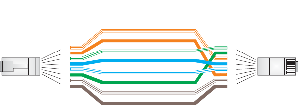
C-4
CROSSOVER WIRING
Because the 10/100 Mbps port on the power injector uses an MDI pin
configuration, you must use “crossover” cable for network connections to PCs,
servers or other end nodes that only have MDI ports. However, if the device to
which you are connecting supports automatic MDI/MDI-X operation, you can use
either “straight-through” or “crossover” cable.
White/Orange Stripe
Orange
White/Green Stripe
1
2
3
4
5
6
7
8
1
2
3
4
5
6
7
8
EIA/TIA 568B RJ-45 Wiring Standard
10/100BASE-TX Crossover Cable
End A End B
Green
Blue
White/Blue Stripe
Brown
White/Brown Stripe
C-5
8-PIN DIN CONNECTOR PINOUT
The Ethernet cable from the power injector connects to an 8-pin DIN connector
on the wireless bridge. This connector is described in the following figure and
table.
8-Pin DIN Ethernet Port Pinout
Pin Signal Name
1Transmit Data plus (TD+)
2Transmit Data minus (TD-)
3Receive Data plus (RD+)
4+48 VDC power
5+48 VDC power
6Receive Data minus (RD-)
7Return power
8Return power
Note: The “+” and “-” signs represent the polarity of the wires that make up each wire pair.
1
7
2
3
4
5
8
6
C-6
8-PIN DIN TO RJ-45 CABLE WIRING
To construct an extended Ethernet cable to connect from the power injector’s
RJ-45 Output port to the wireless bridge’s 8-pin DIN connector, follow the wiring
diagram below. Use Category 5 or better UTP or STP cable, maximum length 100
m (328 ft), and be sure to connect all four wire pairs.
NOTE: To construct a reliable Ethernet cable, always use the proper tools or ask
a professional cable supplier to construct the cable.
White/Orange Stripe
Orange
White/Green Stripe
Green
1
2
3
4
5
6
7
8
1
2
3
4
5
6
7
8
8-Pin DIN
Female RJ-45
1
7
2
3
4
5
8
6
White/Blue Stripe
White/Brown Stripe
Brown
Blue
8-Pin DIN Female
Front View

D-1
DSPECIFICATIONS
GENERAL SPECIFICATIONS
MAXIMUM CHANNELS
802.11a:
US & Canada: 13 (normal mode), 5 (turbo mode)
Japan: 4 (normal mode), 1 (turbo mode)
ETSI: 11 channels (normal mode), 4 (turbo mode)
Taiwan: 8 (normal mode), 3 (turbo mode)
802.11b/g:
FCC/IC: 1-11
ETSI: 1-13
France: 10-13
MKK: 1-14
Taiwan: 1-11
MAXIMUM CLIENTS
64 per VAP interface
OPERATING RANGE
See “Operating Range” on page 6
DATA RATE
802.11a:
Normal Mode: 6, 9, 12, 18, 24, 36, 48, 54 Mbps per channel
Turbo Mode: 12, 18, 24, 36, 48, 54, 96, 108 Mbps per channel
802.11g: 6, 9, 11, 12, 18, 24, 36, 48, 54 Mbps per channel
802.11b: 1, 2, 5.5, 11 Mbps per channel

D-2
MODULATION TYPE
802.11a: BPSK, QPSK, 16-QAM, 64-QAM
802.11g: CCK, BPSK, QPSK, OFDM
802.11b: CCK, BPSK, QPSK
NETWORK CONFIGURATION
Bridge Mode:
Point-to-point and point-to-multipoint
Access Point Mode:
Infrastructure
OPERATING FREQUENCY
802.11a:
5.15 ~ 5.25 GHz (lower band) US/Canada, Japan
5.25 ~ 5.35 GHz (middle band) US/Canada
5.725 ~ 5.825 GHz (upper band) US/Canada
5.50~ 5.70 GHz Europe
5.25 ~ 5.35 GHz (middle band) Taiwan
5.725 ~ 5.825 GHz (high band) Taiwan
802.11b:
2.4 ~ 2.4835 GHz (US, Canada, ETSI)
2.4 ~ 2.497 GHz (Japan)
2.400 ~ 2.4835 GHz (Taiwan)
POWER INJECTOR
Input: 100-240 VAC, 47-63 Hz, 1.5 A
Output: 48 VDC, 1.2 A
Bridge Power (DC)
Input voltage: 48 volts, 1.2 A, 30 watts maximum
PHYSICAL SIZE
19.8 x 19.8 x 6.33 cm (7.8 x 7.8 x 2.49 in)
POE (DC)
Input voltage: 48 volts, 0.2 A, 12.96 watts
NOTE: Power can also be provided to the access point through the Ethernet port
based on IEEE 802.3af Power over Ethernet (PoE) specifications. When both PoE
is provided and the adapter is plugged in, AC power will be turned off.
D-3
WEIGHT
4.8kg (10.58 lbs)
LED INDICATORS
PWR (Power), Link (Ethernet Link/Activity), 11a and 11g (Wireless Link/Activity)
NETWORK MANAGEMENT
Web-browser, RS232 console, Telnet, SSH, SNMP
TEMPERATURE
Operating: 0 to 50 °C (32 to 122 °F)
Storage: 0 to 70 °C (32 to 158 °F)
HUMIDITY
15% to 95% (non-condensing)
COMPLIANCES
FCC Class B (US)
ICES-003 (Canada)
RTTED 1999/5/EC
VCCI (Japan)
RCR STD-33A
RADIO SIGNAL CERTIFICATION
FCC Part 15C 15.247, 15.207 (2.4 GHz)
FCC part 15E 15.407 (5 GHz)
RSS-210 (Canada)
EN 301.893, EN 300.328, EN 301.489-1, EN 301.489-17
MPT RCR std.33 (D33 1~13 Channel, T66 Channel 14)
SAFETY
cCSAus(CSA 22.2 No. 60950-1 & UL60950-1)
EN60950-1 (TÜV/GS), IEC60950-1 (CB)
STANDARDS
IEEE 802.3 10BASE-T, IEEE 802.3u 100BASE-TX,
IEEE 802.11a, b, g

D-4
SENSITIVITY
IEEE 802.11a Sensitivity (GHz - dBm)
Modulation/Rates 5.15-5.250 5.25-5.350 5.50-5.700 5.725-5.825
BPSK (6 Mbps) -88 -88 -88 -88
BPSK (9 Mbps) -87 -87 -87 -87
QPSK (12 Mbps) -86 -86 -86 -86
QPSK (18 Mbps) -84 -84 -84 -84
16 QAM (24 Mbps) -82 -81 -81 -81
16 QAM (36 Mbps) -80 -79 -78 -78
64 QAM (48 Mbps) -73 -73 -73 -73
64QAM(54 Mbps) -70 -70 -69 -67
IEEE 802.11g
Data Rate Sensitivity (dBm)
6 Mbps -88
9 Mbps -87
12 Mbps -86
17 Mbps -85
24 Mbps -81
36 Mbps -77
48 Mbps -72
54 Mbps -70
IEEE 802.11b
Data Rate Sensitivity (dBm)
1 Mbps -93
2 Mbps -90
5.5 Mbps -90
11 Mbps -87

D-5
TRANSMIT POWER
IEEE 802.11a Maximum Output Power (GHz - dBm)
Data Rate 5.15-5.250 5.25-5.350 5.50-5.700 5.725-5.825
6 Mbps 17 17 17 17
9 Mbps 17 17 17 17
12 Mbps 17 17 17 17
8 Mbps 17 17 17 17
24 Mbps 17 17 17 17
36 Mbps 17 17 17 17
48 Mbps 17 17 17 17
54 Mbps 12 17 17 16
IEEE 802.11g Maximum Output Power (GHz - dBm)
Data Rate 2.412 2.417~2.467 2.472
6 Mbps 20 20 18
9 Mbps 20 20 18
12 Mbps 20 20 18
18 Mbps 20 20 18
24 Mbps 20 20 18
36 Mbps 18 19 17
48 Mbps 17 16 15
54 Mbps 15 14 13
IEEE 802.11b Maximum Output Power (GHz - dBm)
Data Rate 2.412 2.417~2.467 2.472
1 Mbps 15 16 15
2 Mbps 15 16 15
5.5 Mbps 15 16 15
11 Mbps 15 16 15

D-6
OPERATING RANGE
Important Notice
Maximum distances posted below are actual tested distance thresholds.
However, there are many variables such as barrier
composition and construction
and local environmental interference
that may impact your actual distances and
cause you to experience
distance thresholds far lower than those posted below.
802.11a Wireless Distance Table
Speed and Distance Ranges
Environment 108
Mbps 72
Mbps 54
Mbps 48
Mbps 36
Mbps 24
Mbps 18
Mbps 12
Mbps 9
Mbps 6
Mbps
Outdoors130 m
99 ft
40 m
131 ft
85 m
279 ft
250 m
820 ft
310 m
1016 ft
400 m
1311 ft
445 m
1459 ft
455 m
1492 ft
465 m
1525 ft
510 m
1672 ft
Indoors215 m
49.5 ft 20 m
66 ft 25 m
82 ft 35 m
115 ft 40 m
131 ft
45 m
148 ft
50 m
164 ft
55 m
180 ft
66 m
216 ft
70 m
230 ft
802.11g Wireless Distance Table
Speed and Distance Ranges
Environment 54
Mbp
s
48
Mbps 36
Mbps 24
Mbps 18
Mbps 12
Mbps 11
Mbps 9
Mbps 6
Mbps 5
Mbps 2
Mbps 1
Mbps
Outdoors182 m
269
ft
100
m
328
ft
300
m
984
ft
330 m
1082
ft
350 m
1148
ft
450 m
1475
ft
470 m
1541
ft
485 m
1590
ft
495 m
1623
ft
510 m
1672
ft
520 m
1705
ft
525 m
1722
ft
Indoors220 m
66 ft 25 m
82 ft 35 m
115
ft
43 m
141 ft 50 m
164 ft 57 m
187 ft
66 m
216 ft
71 m
233 ft
80 m
262 ft
85 m
279 ft
90 m
295 ft
93 m
305 ft
802.11b Wireless Distance Table
Speed and Distance Ranges
Environment 11 Mbps 5.5 Mbps 2 Mbps 1 Mbps
Outdoors1300 m
984 ft 465 m
1525 ft 500 m
1639 ft 515 m
1689 ft
Indoors260 m
197 ft 70 m
230 ft 83 m
272 ft 85 m
279 ft

D-7
NOTE: Outdoor Environment: A line-of-sight environment with no interference
or obstruction between the access point and clients.
NOTE: Indoor Environment: A typical office or home environment with floor to
ceiling obstructions between the access point and clients.
D-8

Glossary-1
GLOSSARY
10BASE-T
IEEE 802.3 specification for 10 Mbps Ethernet over two pairs of Category 3 or better UTP cable.
100BASE-TX
IEEE 802.3u specification for 100 Mbps Fast Ethernet over two pairs of Category 5 or better UTP
cable.
Access Point
An internetworking device that seamlessly connects wired and wireless networks. Access points
attached to a wired network, support the creation of multiple radio cells that enable roaming
throughout a facility.
Ad Hoc
A group of computers connected as an independent wireless network, without an access point.
Advanced Encryption Standard (AES)
An encryption algorithm that implements symmetric key cryptography. AES provides very strong
encryption using a completely different ciphering algorithm to TKIP and WEP.
Authentication
The process to verify the identity of a client requesting network access. IEEE 802.11 specifies two
forms of authentication: open system and shared key.
Backbone
The core infrastructure of a network. The portion of the network that transports information from
one central location to another central location where it is unloaded onto a local system.
Basic Service Set (BSS)
A set of 802.11-compliant stations and an access point that operate as a fully-connected wireless
network.
Beacon
A signal periodically transmitted from the access point that is used to identify the service set, and
to maintain contact with wireless clients.
Glossary-2
Broadcast Key
Broadcast keys are sent to stations using 802.1X dynamic keying. Dynamic broadcast key
rotation is often used to allow the access point to generate a random group key and periodically
update all key-management capable wireless clients.
CSMA/CA
Carrier Sense Multiple Access with Collision Avoidance.
Dynamic Host Configuration Protocol (DHCP)
Provides a framework for passing configuration information to hosts on a TCP/IP network. DHCP
is based on the Bootstrap Protocol (BOOTP), adding the capability of automatic allocation of
reusable network addresses and additional configuration options.
Encryption
Data passing between the access point and clients can use encryption to protect from
interception and evesdropping.
Extended Service Set (ESS)
More than one wireless cell can be configured with the same Service Set Identifier to allow mobile
users can roam between different cells with the Extended Service Set.
Extensible Authentication Protocol (EAP)
An authentication protocol used to authenticate network clients. EAP is combined with IEEE
802.1X port authentication and a RADIUS authentication server to provide “mutual
authentication” between a client, the access point, and the a RADIUS server
Ethernet
A popular local area data communications network, which accepts transmission from computers
and terminals.
File Transfer Protocol (FTP)
A TCP/IP protocol used for file transfer.
Hypertext Transfer Protocol (HTTP)
HTTP is a standard used to transmit and receive all data over the World Wide Web.
IEEE 802.11a
A wireless standard that supports high-speed communications in the 5 GHz band using
Orthogonal Frequency Division Multiplexing (OFDM). The standard supports data rates of 6, 12,
24, and 54 Mbps.
Glossary-3
IEEE 802.11b
A wireless standard that supports wireless communications in the 2.4 GHz band using Direct
Sequence Spread Spectrum (DSSS). The standard provides for data rates of 1, 2, 5.5, and 11
Mbps.
IEEE 802.11g
A wireless standard that supports wireless communications in the 2.4 GHz band using using
Orthogonal Frequency Division Multiplexing (OFDM). The standard provides for data rates of 6,
9, 11, 12, 18, 24, 36, 48, 54 Mbps. IEEE 802.11g is also backward compatible with IEEE 802.11b.
IEEE 802.1X
Port Authentication controls access to the switch ports by requiring users to first enter a user ID
and password for authentication.
Infrastructure
An integrated wireless and wired LAN is called an infrastructure configuration.
Inter Access Point Protocol (IAPP)
A protocol that specifies the wireless signaling required to ensure the successful handover of
wireless clients roaming between different 802.11f-compliant access points.
Local Area Network (LAN)
A group of interconnected computer and support devices.
MAC Address
The physical layer address used to uniquely identify network nodes.
Network Time Protocol (NTP)
NTP provides the mechanisms to synchronize time across the network. The time servers operate
in a hierarchical-master-slave configuration in order to synchronize local clocks within the subnet
and to national time standards via wire or radio.
Open System
A security option which broadcasts a beacon signal including the access point’s configured SSID.
Wireless clients can read the SSID from the beacon, and automatically reset their SSID to allow
immediate connection to the nearest access point.
Orthogonal Frequency Division Multiplexing (ODFM)
OFDM/ allows multiple users to transmit in an allocated band by dividing the bandwidth into many
narrow bandwidth carriers.
Power over Ethernet (PoE)
A specification for providing both power and data to low-power network devices using a single
Category 5 Ethernet cable. PoE provides greater flexibility in the locating of access point’s and
network devices, and significantly decreased installation costs.
Glossary-4
RADIUS
A logon authentication protocol that uses software running on a central server to control access to
the network.
Roaming
A wireless LAN mobile user moves around an ESS and maintains a continuous connection to the
infrastructure network.
RTS Threshold
Transmitters contending for the medium may not be aware of each other. RTS/CTS mechanism
can solve this “Hidden Node Problem.” If the packet size is smaller than the preset RTS
Threshold size, the RTS/CTS mechanism will NOT be enabled.
Service Set Identifier (SSID)
An identifier that is attached to packets sent over the wireless LAN and functions as a password
for joining a particular radio cell; i.e., Basic Service Set (BSS).
Session Key
Session keys are unique to each client, and are used to authenticate a client connection, and
correlate traffic passing between a specific client and the access point.
Shared Key
A shared key can be used to authenticate each client attached to a wireless network. Shared Key
authentication must be used along with the 802.11 Wireless Equivalent Privacy algorithm.
Simple Network Management Protocol (SNMP)
The application protocol in the Internet suite of protocols which offers network management
services.
Simple Network Time Protocol (SNTP)
SNTP allows a device to set its internal clock based on periodic updates from a Network Time
Protocol (NTP) server. Updates can be requested from a specific NTP server, or can be received
via broadcasts sent by NTP servers.
Temporal Key Integrity Protocol (TKIP)
A data encryption method designed as a replacement for WEP. TKIP avoids the problems of
WEP static keys by dynamically changing data encryption keys.
Trivial File Transfer Protocol (TFTP)
A TCP/IP protocol commonly used for software downloads.
Virtual Access Point (VAP)
Virtual AP technology multiplies the number of Access Points present within the RF footprint of a
single physical access device. With Virtual AP technology, WLAN users within the device’s
footprint can associate with what appears to be different access points and their associated
Glossary-5
network services. All the services are delivered using a single radio channel, enabling Virtual AP
technology to optimize the use of limited WLAN radio spectrum.
Virtual LAN (VLAN)
A Virtual LAN is a collection of network nodes that share the same collision domain regardless of
their physical location or connection point in the network. A VLAN serves as a logical workgroup
with no physical barriers, and allows users to share information and resources as though located
on the same LAN.
Wi-Fi Protected Access
WPA employs 802.1X as its basic framework for user authentication and dynamic key
management to provide an enhanced security solution for 802.11 wireless networks.
Wired Equivalent Privacy (WEP)
WEP is based on the use of security keys and the popular RC4 encryption algorithm. Wireless
devices without a valid WEP key will be excluded from network traffic.
WPA Pre-shared Key (PSK)
PSK can be used for small office networks that may not have the resources to configure and
maintain a RADIUS server, WPA provides a simple operating mode that uses just a pre-shared
password for network access.
Glossary-6

1
Numbers
802.11g 94
A
Advanced Encryption Standard See AES
AES 60
configuring 50
AES, configuring 48
authentication 11
cipher suite 119
closed system 107
configuring 11
MAC address 12, 70, 71
type 53, 107
web redirect 20
B
Basic Service Set See BSS
beacon
interval 43, 102
rate 43, 103
BOOTP 89, 90
BPDU 36
BSS 2
C
cable
assignments 1
crossover 4
straight-through 3
channel 43, 98
channels, maximum 1
Clear To Send See CTS
CLI 1
command modes 4
clients, maximum 1
closed system 107
command line interface See CLI
community name, configuring 20, 41
community string 21, 41
configuration settings, saving or restoring 25, 56
configuration, initial setup 1
console port
required settings 1
country code
configuring 3, 12
crossover cable 4
CSMA/CA 1
CTS 44, 105
D
data rate
maximum distances 6
data rate, options 1
default settings 7
device status, displaying 63, 23
DHCP 5, 6, 89, 90
distances, maximum 6
DNS 6, 89
Domain Name Server See DNS
downloading software 24, 56
DTIM 43, 103
E
EAP 59
encryption 48, 53, 54, 59
Ethernet
port 4
event logs 67, 32
Extensible Authentication Protocol See EAP
F
factory defaults
restoring 25, 10
fast forwarding, STP 38
filter 18, 70
address 11, 70
between wireless clients 19, 74
local bridge 19, 74
local or remote 11, 72
management access 19, 74
protocol types 19, 75
VLANs 18, 132
firmware
displaying version 24
upgrading 24, 25, 56
fragmentation 104

2
G
gateway address 2, 6, 1, 89
H
hardware version, displaying 24
HTTP, secure server 19
HTTPS 19
I
IAPP 131
IEEE 802.11a 1, 41, 94
configuring interface 42, 94
maximum data rate 43, 97
radio channel 43, 98
IEEE 802.11b 41
IEEE 802.11f 131
IEEE 802.11g 41
configuring interface 46, 94
maximum data rate 47, 97
radio channel 46, 98
IEEE 802.1x 59, 65, 70
configuring 11, 12, 65
initial setup 1
installation 1
IP address
BOOTP/DHCP 89, 90
configuring 2, 5, 89, 90
L
log
messages 28, 67, 29
server 27, 29
login
CLI 1
web 3
logon authentication
RADIUS client 14, 59
M
MAC address, authentication 12, 70, 71
maximum data rate 43, 47, 97
802.11a interface 43, 97
802.11g interface 47, 97
maximum distances 6
MDI, RJ-45 pin configuration 4
multicast cipher 61
N
network topologies
infrastructure 2
infrastructure for roaming 3
O
OFDM 1
open system 53, 107
operating frequency 2
P
package checklist 2
password
configuring 23, 15
management 23, 15
PoE 8, 11
specifications 2
port priority
STA 86
Power over Ethernet See PoE
power supply, specifications 2
PSK 60
R
radio channel
802.11a interface 43, 98
802.11g interface 46, 98
RADIUS 7, 59
RADIUS, logon authentication 14, 59
Remote Authentication Dial-in User Service See
RADIUS
Request to Send See RTS
reset 25, 10
reset button 4, 25
resetting the access point 25, 10
restarting the system 25, 10
RJ-45 port
configuring duplex mode 91
configuring speed 91
RSSI BNC 5
RTS
threshold 44, 104
S
Secure Socket Layer See SSL
security, options 53

3
session key 13, 67
shared key 49, 56, 121
Simple Network Management Protocol See SNMP
Simple Network Time Protocol See SNTP
SNMP 20, 40
community name 20, 41
community string 41
enabling traps 21, 42
trap destination 21, 43
trap manager 21, 43
SNTP 29, 34
enabling client 29, 34
server 29, 34
software
displaying version 24, 63, 24
downloading 25, 56
SSID 107
SSL 19
STA
interface settings 86 to ??
path cost 86
port priority 86
startup files, setting 55
station status 65, 112
status
displaying device status 63, 23
displaying station status 65, 112
STP
fast forwarding 38
straight-through cable 3
system clock, setting 29, 35
system log
enabling 27, 29
server 27, 29
system software, downloading from server 24, 56
T
Tel ne t
for managenet access 1
Temporal Key Integrity Protocol See TKIP
time zone 30, 36
TKIP 59
transmit power, configuring 43, 98
trap destination 21, 43
trap manager 21, 43
U
upgrading software 24, 56
user name, manager 23, 15
user password 23, 15
V
VLAN
configuration 18, 132
native ID 18
W
WEP 48, 54
configuring 48, 54
shared key 49, 56, 121
Wi-Fi Multimedia See WMM
Wi-Fi Protected Access See WPA
Wired Equivalent Protection See WEP
WPA 59
authentication over 802.11x 61
pre-shared key 61, 125
WPA, pre-shared key See PSK