Hewlett Packard Enterprise WL602 DSL Firewall Router User Manual 3com
Hewlett-Packard Company DSL Firewall Router 3com
Contents
- 1. User Manual Part I
- 2. User Manual Part II
User Manual Part I

http://www.3Com.com/
Part No. 10015880 Rev. AA
Published May 2008
Wireless 11n Cable/DSL Firewall Router
User Guide
WL-602
3CRWER300-73
3Com Corporation
350 Campus Drive,
Marlborough, MA
USA 01752-3064
Copyright © 2004, 2005, 2006, 2007, 2008, 3Com Corporation. All rights reserved. No part of this
documentation may be reproduced in any form or by any means or used to make any derivative work (such as
translation, transformation, or adaptation) without written permission from 3Com Corporation.
3Com Corporation reserves the right to revise this documentation and to make changes in content from time
to time without obligation on the part of 3Com Corporation to provide notification of such revision or change.
3Com Corporation provides this documentation without warranty, term, or condition of any kind, either
implied or expressed, including, but not limited to, the implied warranties, terms or conditions of
merchantability, satisfactory quality, and fitness for a particular purpose. 3Com may make improvements or
changes in the product(s) and/or the program(s) described in this documentation at any time.
If there is any software on removable media described in this documentation, it is furnished under a license
agreement included with the product as a separate document, in the hard copy documentation, or on the
removable media in a directory file named LICENSE.TXT or !LICENSE.TXT. If you are unable to locate a copy,
please contact 3Com and a copy will be provided to you.
UNITED STATES GOVERNMENT LEGEND
If you are a United States government agency, then this documentation and the software described herein are
provided to you subject to the following:
All technical data and computer software are commercial in nature and developed solely at private expense.
Software is delivered as “Commercial Computer Software” as defined in DFARS 252.227-7014 (June 1995) or
as a “commercial item” as defined in FAR 2.101(a) and as such is provided with only such rights as are
provided in 3Com’s standard commercial license for the Software. Technical data is provided with limited rights
only as provided in DFAR 252.227-7015 (Nov 1995) or FAR 52.227-14 (June 1987), whichever is applicable.
You agree not to remove or deface any portion of any legend provided on any licensed program or
documentation contained in, or delivered to you in conjunction with, this User Guide.
Unless otherwise indicated, 3Com registered trademarks are registered in the United States and may or may not
be registered in other countries.
3Com, and the 3Com logo are registered trademarks of 3Com Corporation.
Intel and Pentium are registered trademarks of Intel Corporation. Microsoft, MS-DOS, Windows, and Windows
NT are registered trademarks of Microsoft Corporation. Novell and NetWare are registered trademarks of
Novell, Inc. UNIX is a registered trademark in the United States and other countries, licensed exclusively
through X/Open Company, Ltd.
Netscape Navigator is a registered trademark of Netscape Communications.
JavaScript is a trademark of Sun Microsystems
Wi-Fi and the Wi-Fi logo are registered trademarks of the WI-Fi Alliance.
IEEE and 802 are trademarks of the Institute of Electrical and Electronics Engineers, Inc.
All other company and product names may be trademarks of the respective companies with which they are
associated.
ENVIRONMENTAL STATEMENT
It is the policy of 3Com Corporation to be environmentally-friendly in all operations. To uphold our policy, we
are committed to:
Establishing environmental performance standards that comply with national legislation and regulations.
Conserving energy, materials and natural resources in all operations.
Reducing the waste generated by all operations. Ensuring that all waste conforms to recognized environmental
standards. Maximizing the recyclable and reusable content of all products.
Ensuring that all products can be recycled, reused and disposed of safely.
Ensuring that all products are labelled according to recognized environmental standards.
Improving our environmental record on a continual basis.
End of Life Statement
3Com processes allow for the recovery, reclamation and safe disposal of all end-of-life electronic components.
Regulated Materials Statement
3Com products do not contain any hazardous or ozone-depleting material.
Environmental Statement about the Documentation
The documentation for this product is printed on paper that comes from sustainable, managed forests; it is
fully biodegradable and recyclable, and is completely chlorine-free. The varnish is environmentally-friendly, and
the inks are vegetable-based with a low heavy-metal content.

CONTENTS
ABOUT THIS GUIDE
Naming Convention 7
Conventions 8
Feedback About This User Guide 9
Related Documentation 9
INTRODUCING THE ROUTER
Wireless 11n Cable/DSL Firewall Router 11
Router Advantages 13
Package Contents 13
Minimum System and Component Requirements 14
Physical Features 14
INSTALLING THE ROUTER
Introduction 19
Safety Information 19
Positioning the Router 19
Using the Rubber Feet 20
Wall Mounting 20
Powering Up the Router 21
Connecting the Router 21
SETTING UP YOUR COMPUTERS
Obtaining an IP Address Automatically 23
Windows 2000 23
Windows Vista 25
Windows XP 26
Macintosh 26

Disabling PPPoE and PPTP Client Software 27
Disabling Web Proxy 27
RUNNING THE SETUP WIZARD
Accessing the Setup Wizard 29
Wizard -
Change Password 32
Wizard -
Time and Time Zone 32
Wizard -
Connection Type 33
Setup Wizard - LAN Settings 40
Wizard - Wireless Setting 41
Wizard - Configuration Summary 42
CONFIGURING THE ROUTER
Navigating Through the Router Configuration screens 43
Main Menu 43
Welcome Screen 43
Status 43
LAN Settings 44
LAN Settings 44
DHCP Clients List 45
Wireless Settings 47
Configuration 48
Encryption 49
WPS 54
Connection Control 55
Client List 56
WMM 57
WDS 58
Advanced 59
Internet Settings 60
WAN 60
DNS 67
Clone MAC address 68
Firewall 69
SPI 69
Special Applications 73
Virtual Servers 74
DMZ 75
PC Privileges 76
Schedule Rule 78
URL Filter 79
Advanced 80
Security 80
VLAN 83
Static Routes 84
RIP 85
DDNS 87
SNMP 88
Syslog 89
Proxy ARP 90
QoS Settings 91
VPN 92
System Tools 96
Restart Router 96
Configuration 96
Upgrade 97
Time Zone 98
Ping 99
Traceroute 100
DNS Lookup 101
Status and Logs 102
Status 102
Routing Table 102
Logs 103
Traffic Statistics 103
Support/Feedback 104
Support 104
Feedback 104

TROUBLESHOOTING
Basic Connection Checks 105
Browsing to the Router Configuration Screens 105
Connecting to the Internet 106
Forgotten Password and Reset to Factory Defaults 106
Wireless Networking 107
Recovering from Corrupted Software 109
Frequently Asked Questions 110
IP ADDRESSING
The Internet Protocol Suite 111
Managing the Router over the Network 111
IP Addresses and Subnet Masks 111
How does a Device Obtain an IP Address and Subnet Mask? 113
DHCP Addressing 113
Static Addressing 113
Auto-IP Addressing 113
TECHNICAL SPECIFICATIONS
3Com Wireless 11n Cable/DSL Firewall Router 115
Standards 116
SAFETY INFORMATION
END USER SOFTWARE LICENSE AGREEMENT
OBTAINING SUPPORT FOR YOUR PRODUCT

GLOSSARY
REGULATORY NOTICES
INDEX

ABOUT THIS GUIDE
This guide describes how to install and configure the 3Com Wireless 11n
Cable/DSL Firewall Router (3CRWER300-73).
This guide is intended for use by those responsible for installing and
setting up network equipment; consequently, it assumes a basic working
knowledge of LANs (Local Area Networks) and Internet Routers.
If a release note is shipped with the 3Com Wireless 11n Cable/DSL
Firewall Router and contains information that differs from the
information in this guide, follow the information in the release note.
Most user guides and release notes are available in Adobe Acrobat
Reader Portable Document Format (PDF) on the 3Com World Wide Web
site:
http://www.3Com.com
Naming Convention Throughout this guide, the 3Com Wireless 11n Cable/DSL Firewall Router
is referred to as the “Router”.
Category 3 and Category 5 Twisted Pair Cables are referred to as Twisted
Pair Cables throughout this guide.
8ABOUT THIS GUIDE
Conventions Table 1 and Ta b l e 2 list conventions that are used throughout this guide.
Table 1 Notice Icons
Icon Notice Type Description
Information note Information that describes important features or
instructions.
Caution Information that alerts you to potential loss of data or
potential damage to an application, system, or device.
Warning Information that alerts you to potential personal
injury.
Table 2 Text Conventions
Convention Description
The words “enter”
and “type”
When you see the word “enter” in this guide, you must type
something, and then press Return or Enter. Do not press
Return or Enter when an instruction simply says “type.”
Keyboard key names If you must press two or more keys simultaneously, the key
names are linked with a plus sign (+). Example:
Press Ctrl+Alt+Del
Words in italics Italics are used to:
■Emphasize a point.
■Denote a new term at the place where it is defined in the
text.
■Identify menu names, menu commands, and software
button names. Examples:
From the Help menu, select Contents.
Click OK.

Feedback About This User Guide 9
Feedback About
This User Guide
Your suggestions are very important to us. They will help make our
documentation more useful to you. Please e-mail comments about this
document to 3Com at:
pddtechpubs_comments@3com.com
Please include the following information when commenting:
■Document title
■Document part number (on the title page)
■Page number (if appropriate)
Example:
■3Com Wireless 11n Cable/DSL Firewall Router User Guide
■Part Number 10015880 Rev. AA
■Page 24
Do not use this e-mail address for technical support questions. For
information about contacting Technical Support, please refer to
Appendix C.
Related
Documentation
In addition to this guide, each Router document set includes one
Installation Guide. This guide contains the instructions you need to install
and configure your Router.
10 ABOUT THIS GUIDE

1INTRODUCING THE ROUTER
Welcome to the world of networking with 3Com®. In the modern
business environment, communication and sharing information is crucial.
Computer networks have proved to be one of the fastest modes of
communication but, until recently, only large businesses could afford the
networking advantage.
Wireless 11n
Cable/DSL Firewall
Router
The 3Com Wireless 11n Cable/DSL Firewall Router is designed to provide
a cost-effective means of sharing a single broadband Internet connection
amongst several wired and wireless computers. The Router also provides
protection in the form of an electronic “firewall” preventing anyone
outside of your network from seeing your files or damaging your
computers. The Router can also prevent your users from accessing Web
sites which you find unsuitable.
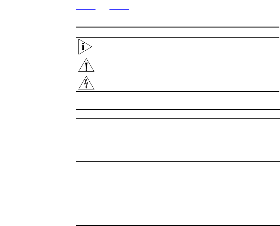
Figure 1 shows an example network without a Router. In this network,
only one computer is connected to the Internet. This computer must
always be powered on for the other computers on the network to access
the Internet.
12 CHAPTER 1: INTRODUCING THE ROUTER
Figure 1 Example Network Without a Router
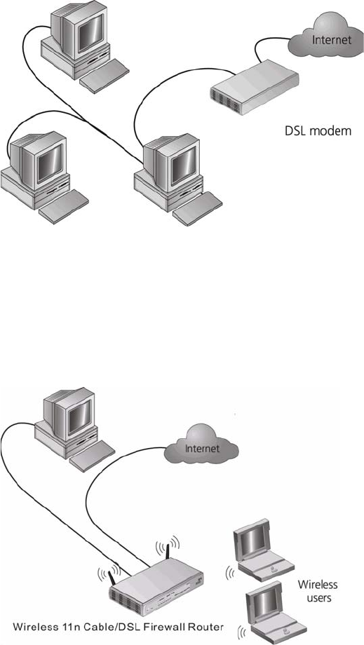
When you use the Router in your network (Figure 2), it becomes your
connection to the Internet. Connections can be made directly to the
Router, or to an OfficeConnect Switch or Hub, expanding the number of
computers you can have in your network.
Figure 2 Example Network Using a Firewall Router

Router Advantages 13
Router Advantages The advantages of the Router include:
■Shared Internet connection for both wired and wireless computers
■High speed 802.11n wireless networking
■No need for a dedicated, “always on” computer serving as your
Internet connection
■Cross-platform operation for compatibility with Windows, Unix and
Macintosh computers
■Easy-to-use, Web-based setup and configuration
■Provides centralization of all network address settings (DHCP)
■Acts as a Virtual server to enable remote access to Web, FTP, and other
services on your network
■Security — Firewall protection against Internet hacker attacks and
encryption to protect wireless network traffic
Package Contents The Router kit includes the following items:
■One 3Com Wireless 11n Cable/DSL Firewall Router
■One power adapter for use with the Router
■Four rubber feet
■One Ethernet cable
■One CD-ROM containing this User guide
■Installation guide
■Support and Safety sheet
■Warranty sheet
■Product range sheet
If any of these items are missing or damaged, please contact your retailer.
14 CHAPTER 1: INTRODUCING THE ROUTER
Minimum System
and Component
Requirements
Your Router requires that the computer(s) and components in your
network be configured with at least the following:
■A computer with an operating system that supports TCP/IP
networking protocols (for example Windows 2000/XP,/Vista, Unix,
Mac OS 8.5 or higher).
■An Ethernet 10 Mbps or 10/100 Mbps NIC for each computer to be
connected to the four-port switch on your Router.
■An 802.11b or 802.11g or 802.11n wireless NIC.
■An active ADSL or Cable subscription and connection.
■A Web browser that supports JavaScript, such as Netscape 4.7 or
higher, Internet Explorer 6.0 or higher, or Mozilla 1.2.1 or higher.
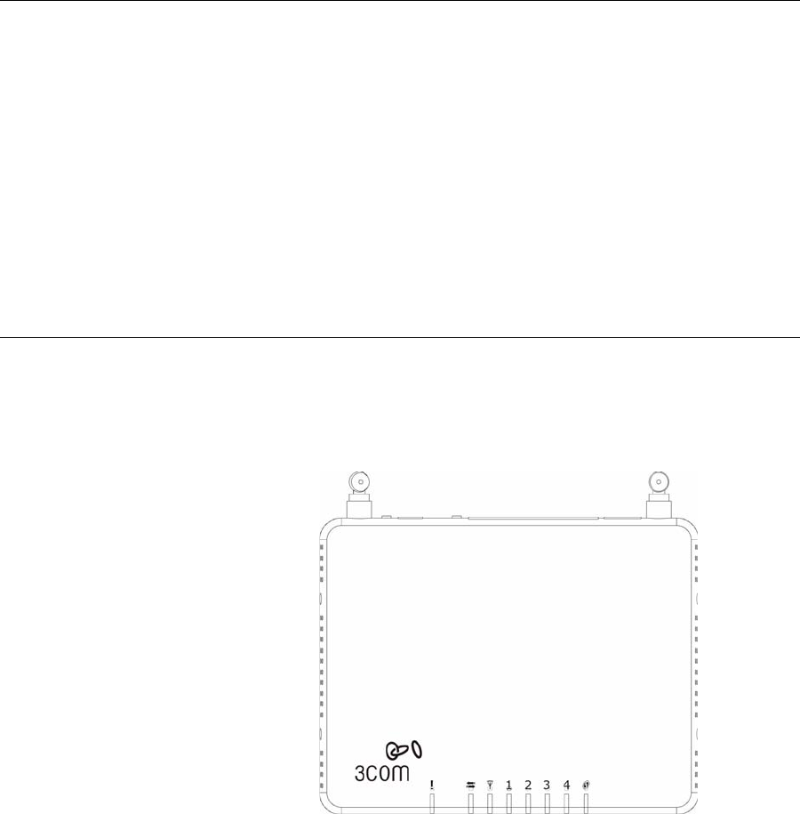
Physical Features The front panel of the Router contains a series of indicator lights (LEDs)
that help describe the state of various networking and connection
operations.
Figure 3 Router - Front Panel

Physical Features 15
1 Alert LED
Amber
Fast flash during self test. If self test fails the LED will remain on.
Fast flash during software upgrade.
Fast flash for software reset to the factory defaults.
Fast flash for hardware reset to the factory defaults.
The LED is on for 2 seconds when the firewall detects a hacker attack.
2Cable/DSL
Blue
LED on indicates the physical connection is on.
Fast flash means WAN port traffic activity.
3 Wireless LAN (WLAN) Status LED
Blue
If the LED is on it indicates that wireless networking is enabled. If the LED
is flashing, the link is OK and data is being transmitted or received. If the
LED is off, the Wireless LAN has been disabled in the Router, or there is a
problem. Refer to Chapter 6 Troubleshooting.
4 LAN Status LEDs (4 indicators)
Blue
If the LED is on, the link between the port and the next piece of network
equipment is OK. If the LED is flashing, the link is OK and data is being
transmitted or received. If the LED is off, nothing is connected, or the
connected device is switched off, or there is a problem with the
connection (refer to Chapter 6 Troubleshooting). The port will
automatically adjust to the correct speed and duplex.
5 WPS LED
LED on indicates the WPS function is active.
16 CHAPTER 1: INTRODUCING THE ROUTER
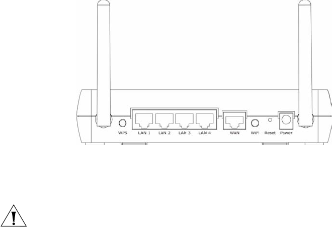
The rear panel (Figure 4) of the Router contains one WPS button, four
LAN ports, one WAN port, one WiFi LED, a reset button, and a power
adapter socket.
Figure 4 Router - Rear Panel
1 Wireless Antennae
The antennaes should be placed in a ‘V’ position when initially installed.
CAUTION: Do not force the antennae beyond their mechanical stops.
Rotating the antennae further may cause damage.
2 WPS button
Press this button when making WPS setup.
3 Ethernet Ports (4 ports)
Using suitable RJ-45 cables, you can connect your Router to a computer,
or to any other piece of equipment that has an Ethernet connection (for
example, a hub or a switch). These ports have an automatic MDI/MDIX
feature, which means either straight-through or a crossover cable can be
used.
4WAN Port
RJ-45 port used to connect the Router with Cable/DSL modem.
5 WiFi On/Off button
Use this button to turn on/turn off the wireless function.

Physical Features 17
6 Reset Button
If you want to reset your Router to factory default settings, or cannot
access the web management interface (for example, due to a lost
password), then you may use this button. Refer to Forgotten Password
and Reset to Factory Defaults on page 106 for further details.
7 Power Adapter Socket
Only use the power adapter that is supplied with this Router. Do not use
any other adapter.
18 CHAPTER 1: INTRODUCING THE ROUTER

2INSTALLING THE ROUTER
Introduction This chapter will guide you through a basic installation of the Router,
including:
■Connecting the Router to the Internet.
■Connecting the Router to your network.
■Setting up your computers for networking with the Router.
Safety Information Please note the following:
WARNING: Please read the Safety Information section in Appendix C
before you start.
VORSICHT: Bitte lesen Sie den Abschnitt Wichtige Sicherheitshinweise
sorgfältig durch, bevor Sie das Gerät einschalten.
AVERTISSEMENT: Veuillez lire attentivement la section Consignes
importantes de sécurité avant de mettre en route.
Positioning the
Router
You should place the Router in a location that:
■is conveniently located for connection to the telephone socket.
■is centrally located to the wireless computers that will connect to the
Router. A suitable location might be on top of a high shelf or similar
furniture to optimize wireless connections to computers in both
horizontal and vertical directions, allowing wider coverage.
■allows convenient connection to the computers that will be connected
to the four LAN ports on the rear panel, if desired.
■allows easy viewing of the front panel LED indicator lights, and access
to the rear panel connectors, if necessary.

20 CHAPTER 2: INSTALLING THE ROUTER
When positioning your Router, ensure:
■It is out of direct sunlight and away from sources of heat.
■Cabling is away from power lines, fluorescent lighting fixtures, and
sources of electrical noise such as radios, transmitters and broadband
amplifiers.
■Water or moisture cannot enter the case of the unit.
■Air flow around the unit and through the vents in the side of the case
is not restricted. 3Com recommends you provide a minimum of
25 mm (1 in.) clearance.
Using the Rubber
Feet
Use the four self-adhesive rubber feet to prevent your Router from
moving around on your desk or when stacking with flat top units. Only
stick the feet to the marked areas at each corner of the underside of your
Router.
Wall Mounting There are two slots on the underside of the Router that can be used for
wall mounting.
When wall mounting the unit, ensure that it is within reach of the power
outlet.
There are 2 slots on the underside of the Router that can be used for wall
mounting. The distance between the 2 slots is 100 mm.
You will need 2 suitable screws, the diameter would be 5.0 to 7.0 mm, to
wall mount the Router.
When wall mounting the unit, ensure that it is within reach of the power
outlet.
To wall mount the unit:
1Ensure that the wall you use is smooth, flat, dry and sturdy and make two
screw holes which are 100 mm apart.
2Fix the screws into wall, leaving their heads 5 mm clear of the wall
surface.
3Remove any connections to the unit and locate it over the screw heads.
When in line, gently push the unit on to the wall and move it downwards
to secure.

Powering Up the Router 21
When making connections, be careful not to push the unit up and off the
wall.
CAUTION: Only wall mount single units, do not wall mount stacked
units.
Powering Up the
Router
To power up the Router:
1Plug the power adapter into the power adapter socket located on the
back panel of the Router.
2Plug the power adapter into a standard electrical wall socket.
Connecting the
Router
The first step for installing your Router is to physically connect it to the
DSL/Cable modem, and then connect the Router to a computer in order
to be able to access the Internet. See Figure 5:
Figure 5 Connecting the Router
22 CHAPTER 2: INSTALLING THE ROUTER
1Using RJ-45 cable to connect the WAN port of the Router with the
DSL/Cable modem.
2Using RJ-45 cable to connect one PC with the LAN port the Router.
You have now completed the hardware installation of your Router. Next
you need to set up your computers so that they can make use of the
Router to communicate with the Internet.
3Com recommends that you perform the initial Router configuration
from a computer that is directly connected to one of the LAN ports.
If you configure the Router from a wireless computer, note that you may
lose contact with the Router if you change the wireless configuration.
To communicate wirelessly with your Router, your wireless NIC should be
set as follows:
■Encryption — none
■SSID — 3Com
■Channel — 11

3SETTING UP YOUR COMPUTERS
The Router has the ability to dynamically allocate network addresses to
the computers on your network, using DHCP. However, your computers
need to be configured correctly for this to take place. To change the
configuration of your computers to allow this, follow the instructions in
this chapter.
Obtaining an IP
Address
Automatically
Windows 2000 If you are using a Windows 2000-based computer, use the following
procedure to change your TCP/IP settings:
1From the Windows Start Menu, select Settings > Control Panel.
2Double click on Network and Dial-Up Connections.
3Double click on Local Area Connection.
4Click on Properties.
5A screen similar to Figure 6 should be displayed. Select Internet Protocol
TCP/IP and click on Properties.
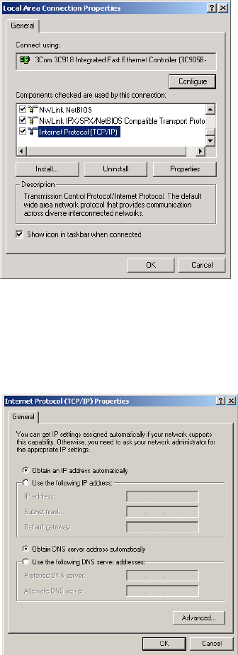
24 CHAPTER 3: SETTING UP YOUR COMPUTERS
Figure 6 Local Area Properties Screen
6Ensure that the options Obtain an IP address automatically, and Obtain
DNS server address automatically are both selected as shown in Figure 7.
Click OK.
Figure 7 Internet Protocol (TCP/IP) Properties Screen
7Restart your computer.
Obtaining an IP Address Automatically 25
Windows Vista
1From the Windows Start Menu, select Settings > Network.
2Click on Organize. Select Properties.
3Click on Manage network > Connections.
4Double click Local Area Connection. Select Properties and click continue.
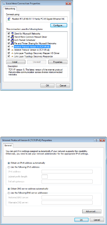
5A screen similar to (Figure 8) should appear. Select Internet Protocol
Version 6,Version 4 (TCP/IPv6,v4) and click on Properties.
Figure 8 Local Area Connection Properties Screen
6Ensure that the options Obtain an IPv6,v4 address automatically, and
Obtain DNS servers address automatically are both selected as shown in
(Figure 9). Click OK.
Figure 9 Internet Protocol Version 6 (TCP/IPv6) Properties Screen
26 CHAPTER 3: SETTING UP YOUR COMPUTERS
Windows XP
1From the Windows Start Menu, select Control Panel.
2Click on Network and Internet Connections.
3Click on the Network Connections icon.
4Double click on LAN or High Speed Connection icon. A screen titled Local
Area Connection Status will appear.
5Select Internet Protocol TCP/IP and click on Properties.
6Ensure that the options Obtain an IP address automatically, and Obtain
DNS servers automatically are both selected. Click OK.
7Restart your computer.
Macintosh If you are using a Macintosh computer, use the following procedure to
change your TCP/IP settings:
1From the desktop, select Apple Menu, Control Panels, and TCP/IP.
2In the TCP/IP control panel, set Connect Via: to Ethernet.
3In the TCP/IP control panel, set Configure: to Using DHCP Server.
4Close the TCP/IP dialog box, and save your changes.
5Restart your computer.
Disabling PPPoE and PPTP Client Software 27
Disabling PPPoE
and PPTP Client
Software
If you have PPPoE client software installed on your computer, you will
need to disable it. To do this:
1From the Windows Start Menu, select Settings > Control Panel.
2Double click on Internet Options.
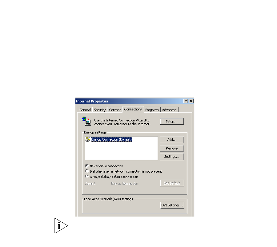
3Select the Connections Tab. A screen similar to Figure 10 should be
displayed.
4Select the Never dial a connection option.
Figure 10 Internet Properties Screen
You may want to remove the PPPoE client software from your computer
to free resources, as it is not required for use with the Router.
Disabling Web
Proxy
Ensure that you do not have a web proxy enabled on your computer.
Go to the Control Panel and click on Internet Options. Select the
Connections tab and click LAN Settings at the bottom. Make sure that
the Use Proxy Server option is unchecked.
28 CHAPTER 3: SETTING UP YOUR COMPUTERS
4RUNNING THE SETUP WIZARD
Accessing the Setup
Wizard
The Router setup program is Web-based, which means that it is accessed
through your Web browser (Netscape Navigator 4.7 or higher, Internet
Explorer 6.0 or higher, or Mozilla 1.2.1 or higher).
To use the Setup Wizard:
1Ensure that you have at least one computer connected to the Router.
Refer to Chapter 2 for details on how to do this.
2Launch your Web browser on the computer.
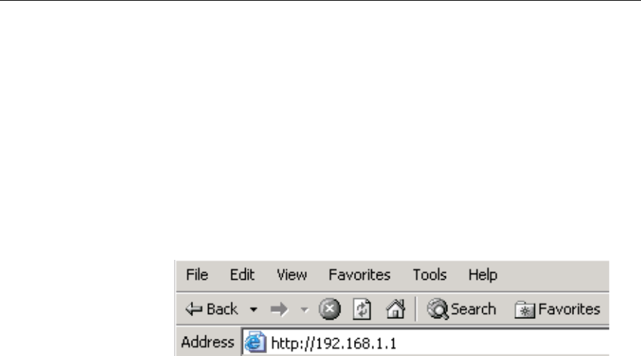
3Enter the following URL in the location or address field of your browser:
http://192.168.1.1 (Figure 11). The Login screen displays.
Figure 11 Web Browser Location Field (Factory Default)
30 CHAPTER 4: RUNNING THE SETUP WIZARD
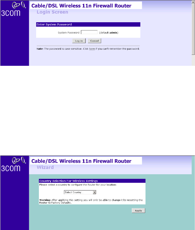
4To log in as an administrator, enter the password (the default password is
admin) in the System Password field and click Log in (see Figure 12).
Figure 12 Router Login Screen
5When you have logged in,
■if you are logging in for the first time, the Country Selection screen
will appear (see Figure 13). Please select the country form the
drop-down menu, and click Apply.
Note to US model owner: To comply with US FCC regulation, the country
selection function has been completely removed from all US models. The
above function is for non-US models only.
Figure 13 Country Selection Screen
The Wizard will then launch automatically (refer to Figure 16). You will be
guided step by step through a basic setup procedure.
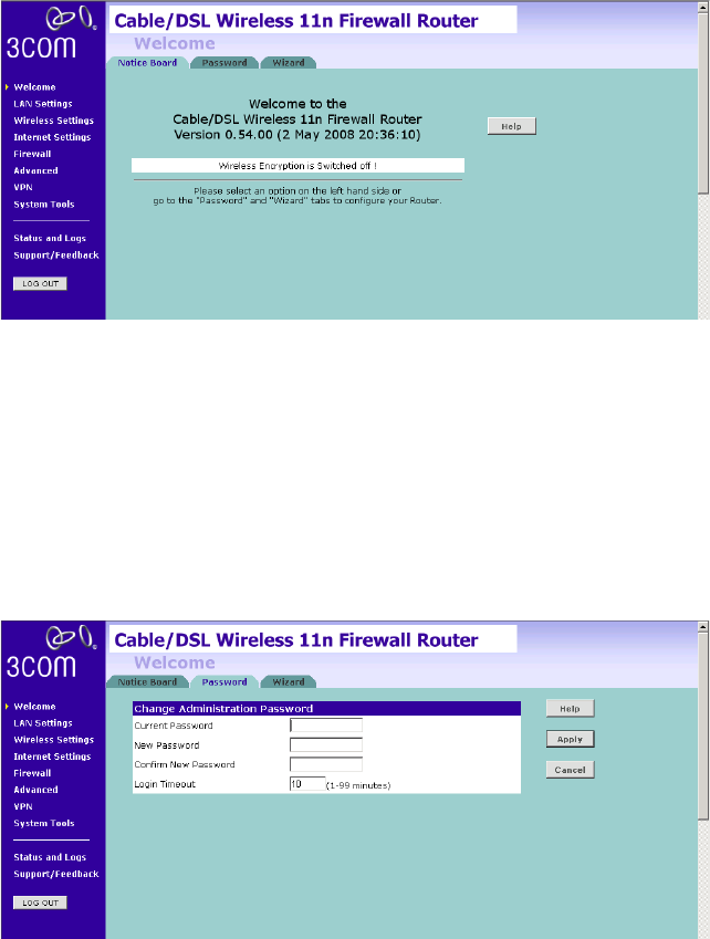
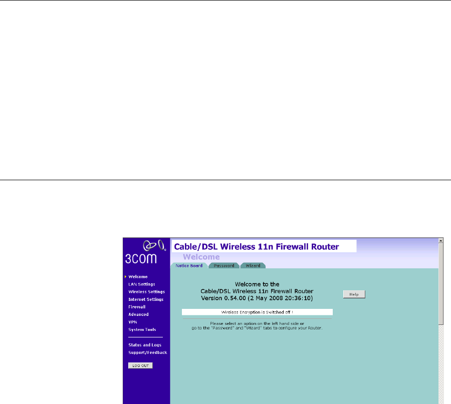
■if the Router has been configured previously, the Welcome screen will
appear (Figure 14). There are three tabs: Notice Board, Password and
Wizard.
Accessing the Setup Wizard 31
Figure 14 Welcome Screen
■Go to the Notice Board tab to see the current software information. To
view the Web help, click the Help button.
■Go to the Password tab to change the password (Figure 15).
■Go to the Wizard tab to do a quick setup of the Router (Figure 16).
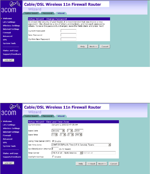
The password screen allows you to change the current password and set
the login time limit to the Router’s management interface.
Figure 15 Password Screen
1To change the current password, enter the password in the Current
Password field.
2Enter the new password in the New Password field, and enter it again in
the Confirm New Password field.
32 CHAPTER 4: RUNNING THE SETUP WIZARD
3Enter the time period in Login Timeout to set a maximum period of time
for which the login session is maintained during inactivity (Default: 10
minutes).
Wizard -
Change Password
To ensure the security of your Router, it is recommended that you choose
a new password - this should be a mix of letters and numbers, and not
easily guessed by others. To leave the current password unchanged, leave
the fields blank and click Next.
Figure 16 Change Password Screen
Wizard -
Time and Time Zone
The Time and Time Zone screen allows you to set up the time for the
Router.
Figure 17 Time and Time Zone Screen
Accessing the Setup Wizard 33
1Select the correct base date and time.
2If you want to automatically synchronize the Router with a public time
server, check the Enable box in the Using Time Server (NTP) field.
3Select the time zone in the Set Time Zone drop-down menu.
4Enter the time in the Synchronization Interval field.
5Select the desired servers from the Time Server drop-down menu.
6Check the Enable box in the Daylight Savings field, if daylight savings
applies to your area.
7Click Next.
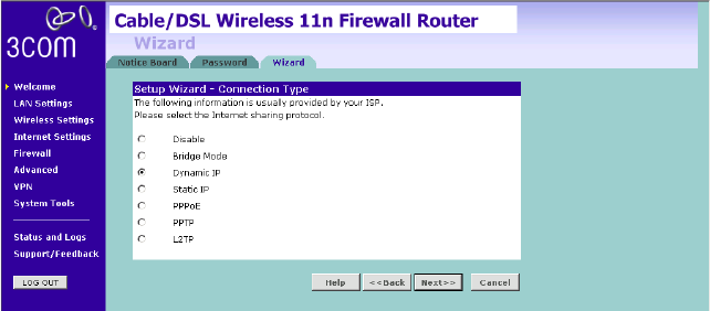
Wizard -
Connection Type
The Connection Type screen allows you to set up the Router for the type
of Internet connection you have. Before setting up your connection type,
have your account information from your ISP ready.
Figure 18 Connection Type Screen
Select a mode from the following:
■Disable — selecting this option means you do not want the Router to
connect to Internet.
■Bridge Mode — RFC1483 Bridged Mode, see page 34
■Dynamic IP — Using DHCP function, see page 35
■Static IP — Using fixed IP, see page 36
■PPPoE — PPP over Ethernet, providing routing for multiple PCs, see
page 37
34 CHAPTER 4: RUNNING THE SETUP WIZARD
■PPTP — Point-to-Point Tunneling Protocol, see page 38
■L2TP — Layer 2 Tunneling Protocol, see page 39
and click Next.
For further information on selecting a mode see Internet Settings on
page 60.
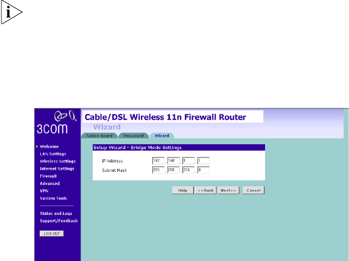
Bridge Mode
To set up the Router for use with an RFC1483 bridged connection, use
the following procedure:
Figure 19 Bridged Mode Screen
1Enter the IP address and Subnet mask information.
2Check all of your settings, and then click Next.
The LAN Settings screen will then be displayed (refer to Figure 25).
Accessing the Setup Wizard 35
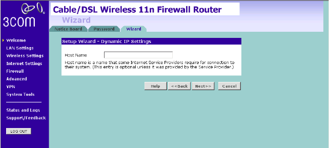
Dynamic IP
To set up the Router for use with a dynamic IP connection, use the
following procedure:
Figure 20 Host Name Screen
1Host name is a name that some Internet Service Providers require for
connection to their system. This entry is optional, your Internet Service
Provider should provide this information.
2Check all of your settings, and then click Next.
The LAN Settings screen will then be displayed (refer to Figure 25).
36 CHAPTER 4: RUNNING THE SETUP WIZARD
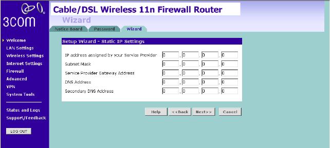
Static IP
To set up the Router for use with a static IP connection, use the following
procedure:
Figure 21 Static IP Screen
To assign a fixed IP address:
1Enter your Internet IP address in the IP address assigned by your Service
Provider field.
2Enter the subnet mask in the Subnet Mask field.
3Enter the default gateway IP address in the Service Provider Gateway
Address field.
4Enter the DNS address in the DNS Address field.
5If there is a secondary DNS, enter the IP address in the Secondary DNS
Address field.
6Check all of your settings, and then click Next.
The LAN Settings screen will then be displayed (refer to Figure 25).
Accessing the Setup Wizard 37
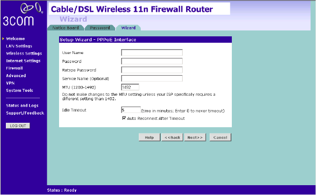
PPPoE Mode
To set up the Router for use with a PPPoE (PPP over Ethernet) connection,
use the following procedure:
Figure 22 PPPoE Screen
1Enter your user name in the Username field.
2Enter your password in the Password field.
3Re-type your password in the Retype Password field.
4The Service Name field is optional, enter this information if your ISP
requires it.
5Enter the MTU information, the default is 1492.
6Enter the maximum Idle Timeout for the Internet connection. After this
time has been exceeded the connection will be terminated. Check the
Auto Reconnect After Timeout box to automatically re-establish the
connection as soon as you attempt to access the Internet again.
7Check all of your settings, and then click Next.
The LAN Settings screen will then be displayed (refer to Figure 25).
38 CHAPTER 4: RUNNING THE SETUP WIZARD
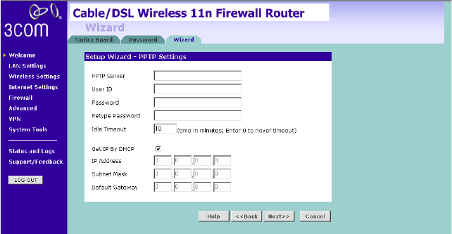
PPTP Mode
To set up the Router for use with a PPTP (Point to Point Tunneling
Protocol) connection, use the following procedure:
Figure 23 PPTP Screen
1Enter the PPTP Server information.
2Enter the User ID and Password required by your ISP.
3Retype the password.
4Enter the maximum Idle Timeout for the Internet connection. After this
time has been exceeded the connection will be terminated.
5Check the Get IP By DHCP box to receive IP address from your ISPs’ DHCP
function. If this box is not checked, enter the IP address, Subnet mask,
and Default Gateway information.
6Check all of your settings, and then click Next.
The LAN Settings screen will then be displayed (refer to Figure 25).

Accessing the Setup Wizard 39
L2TP mode
To set up the Router for use with a L2TP (Layer 2 Tunneling Protocol)
connection, use the following procedure:
Figure 24 L2TP Screen
1Enter the L2TP Server information.
2Enter the User ID and Password required by your ISP.
3Retype the password.
4Enter the maximum Idle Timeout for the Internet connection. After this
time has been exceeded the connection will be terminated.
5Check the Get IP By DHCP box to receive IP address from your ISP’s DHCP
function. If this box is not checked, enter the IP address, Subnet mask,
and Default Gateway information.
6Check all of your settings, and then click Next.
The LAN Settings screen will then be displayed (refer to Figure 25).
40 CHAPTER 4: RUNNING THE SETUP WIZARD
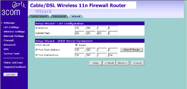
Setup Wizard - LAN
Settings
The LAN Settings screen allows you to set the default IP address and
DHCP client IP range for the Router.
Figure 25 The LAN Settings Screen
1To change the Router’s default IP address, enter the new IP address in the
IP Address field, and then enter the subnet mask in the Subnet Mask
field.
2Check the DHCP Server box to enable the DHCP function.
3Enter the client IP address range in the IP Pool Start Address and IP Pool
End Address fields. You can also click Auto IP Range to automatically set
the starting and ending IP address: 192.168.1.2 ~ 192.168.1.254.
4Click Next. The Wireless Settings screen will be displayed (refer to
Figure 26).
Accessing the Setup Wizard 41
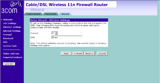
Wizard - Wireless
Setting
The Wireless Settings screen allows you to set up the SSID and radio
channel used for the wireless connection.
Figure 26 Wireless Setting Screen
1Select the channel you want to use from the Channel drop-down menu.
2Specify the SSID to be used by your wireless network in the SSID field. If
there are other wireless networks in your area, you should give your
wireless network a unique name.
42 CHAPTER 4: RUNNING THE SETUP WIZARD
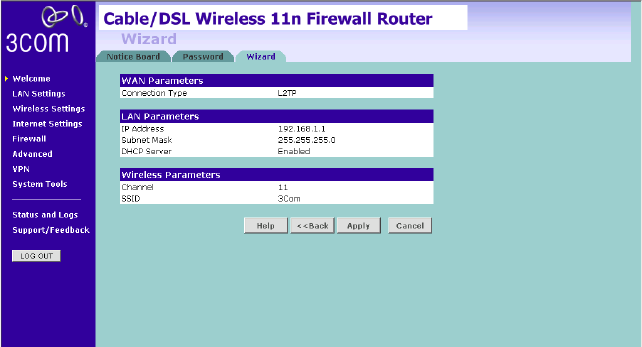
Wizard -
Configuration
Summary
When you have completed the Setup Wizard, a configuration summary
will appear. Verify the configuration information of the Router and then
click Apply to save your settings. 3Com recommends that you print out
this page for your records.
Figure 27 Configuration Summary Screen
Your Router is now configured and ready for use.
See Chapter 5 for a detailed description of the Router configuration.
5CONFIGURING THE ROUTER
Navigating
Through the Router
Configuration
screens
This chapter describes all the screens available through the Router
configuration screens, and is provided as a reference. To get to the
configuration screens, enter the Router’s default IP in the location bar of
your browser. The default IP is http://192.168.1.1.
However, if you changed the Router LAN IP address during initial
configuration, use the new IP address instead. Enter your password to
login to the management interface. (The default password is admin).
Main Menu The main menu is located on the left side, as shown in Figure 28. When
you click on an item from the main menu, the corresponding screen will
then appear in the center.
Welcome Screen The Welcome screen shows the current software information.
Status Figure 28 Welcome Screen
44 CHAPTER 5: CONFIGURING THE ROUTER
LAN Settings Your Router is equipped with a DHCP server that will automatically assign
IP addresses to each computer on your network. The factory default
settings for the DHCP server will work with most applications. If you need
to make changes to the settings, you can do so.
The LAN settings screen allows you to:
■Change the default IP address of the Router. The default IP is
192.168.1.1
■Change the Subnet Mask. The default setting is 255.255.255.0
■Enable/Disable the DHCP Server Function. The default is “Enable”.
■Specify the Starting and Ending IP Pool address. The default is
Starting: 2 / Ending: 254.
■Specify the IP address Lease Time. The default is One day.
■Specify a local Domain Name. This field is optional.
■Specify the IP address of 3Com NBX call processor.
The Router will also provide a list of all client computers connected to the
Router.
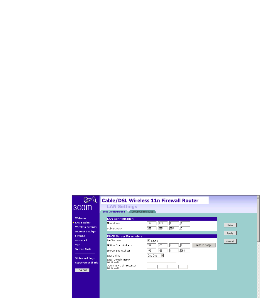
LAN Settings The LAN Settings screen is used to specify the LAN IP address of your
Router, and to configure the DHCP server.
Figure 29 LAN Settings Screen
LAN Settings 45
1Enter the Router’s IP Address and Subnet Mask in the appropriate fields.
The default IP address is 192.168.1.1.
2If you want to use the Router as a DHCP Server, check Enable in the DHCP
Server field.
3Enter the IP address range in the IP Pool Start Address and IP Pool End
Address fields.
4Specify the DHCP Lease time by selecting the required value from the
Lease Time drop-down menu. The lease time is the length of time the
DHCP server will reserve the IP address for each computer.
5Specify the Local Domain Name for your network (this step is optional).
6Enter the IP address of the NBX Call Processor in the 3Com NBX Call
Processor field (this step is optional).
7Check all of your settings, and then click Apply.
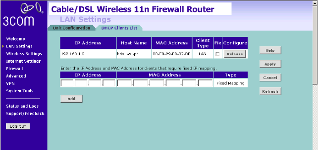
DHCP Clients List The DHCP Clients List provides details on the devices that have received IP
addresses from the Router. The list is only created when the Router is set
up as a DHCP server. A maximum of 253 clients can be connected to the
Router.
Figure 30 DHCP Clients List Screen
For each device that is connected to the LAN, the following information is
displayed:
■IP address — The Internet Protocol (IP) address issued to the client
machine.

46 CHAPTER 5: CONFIGURING THE ROUTER
■Host Name — The client machine’s host name, if configured.
■MAC Address — The Media Access Control (MAC) address of the
client’s network card.
■Client Type — Whether the client is connected to the Router by wired
or wireless connection.
■Check the Fix checkbox to permanently fix the IP address.
■Click Release to release the displayed IP address.
■Click Add to allocate an IP address to a MAC address. Enter the
required details and click Apply to save your settings.
The DHCP server will give out addresses to both wired and wireless
clients.
Wireless Settings 47
Wireless Settings The Wireless Settings screens allow you to configure the settings for the
wireless connections.
You can enable or disable the wireless connection for your LAN. When
disabled, no wireless PCs can gain access to either the Internet or other
PCs on your wired or wireless LAN through this Router.
Figure 31 Wireless Settings Screen
There are 8 tabs available:
■Configuration
■Encryption
■WPS
■Connection Control
■Client List
■WMM
■WDS
■Advanced
48 CHAPTER 5: CONFIGURING THE ROUTER
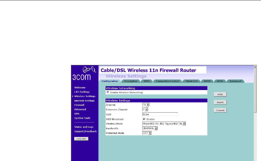
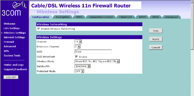
Configuration The Wireless Configuration Screen allows you to turn on/ turn off the
wireless function, and set up basic wireless settings.
Figure 32 Wireless Configuration Screen
To enable the wireless function:
1Check Enable Wireless Networking checkbox.
2Select the wireless channel you want to use from the Channel drop-down
menu.
3Select the Extension Channel.
4Specify the SSID to be used by your wireless network in the SSID field. If
there are other wireless networks in your area, you should give your
wireless network an unique name.
5Enable or disable SSID Broadcast.
A feature of many wireless network adapters is that a computer's SSID
can be set to ANY, which means it looks randomly for any existing
wireless network. The available networks are then displayed in a site
survey, and your computer can select a network. If you disable this SSID
broadcast function, you can block this random search, and set the
computer's SSID to a specific network (for example, WLAN). This
increases network security. If you decide to enable SSID Broadcast, ensure
that you know the name of your network first.
6Select whether your Router will operate in 11b mode only, 11g mode
only, 11n mode only, or mixed mode from the Wireless Mode drop-down
menu.
7Bandwidth: select the bandwidth to use.
Wireless Settings 49
8Select to turn on/off the Protected Mode function.
9Click Apply.
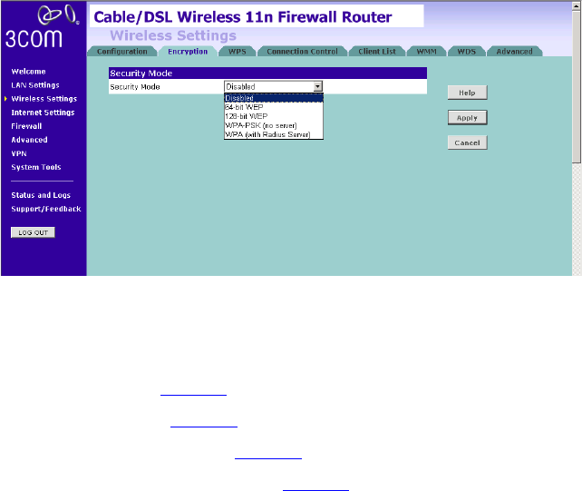
Encryption This feature prevents any non-authorized party from reading or changing
your data over the wireless network.
Figure 33 Encryption Screen
Select the wireless security mode that you want to use from the
drop-down menu, and click Apply. There are five selections:
■Disabled
■64-bit WEP (see page 50)
■128-bit WEP (see page 51)
■WPA-PSK (no server) (see page 52)
■WPA (with RADIUS Server) (see page 53)
Disabled
In this mode, wireless transmissions will not be encrypted, and will be
visible to everyone. However, when setting up or debugging wireless
networks, it is often useful to use this security mode.
50 CHAPTER 5: CONFIGURING THE ROUTER
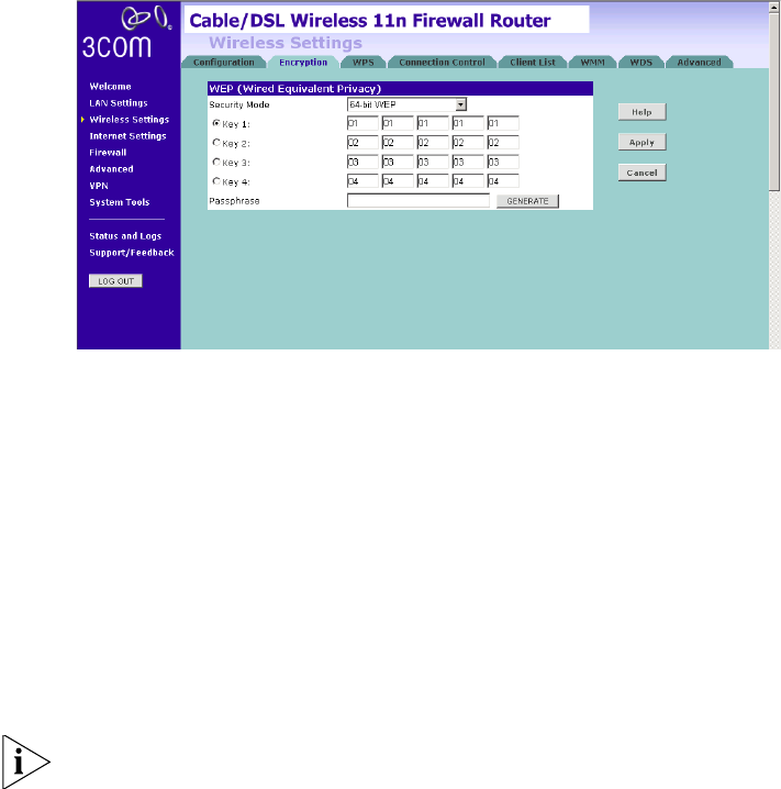
64-bit WEP
WEP is the basic mechanism to transmit your data securely over the
wireless network. Matching encryption keys must be setup on your
Router and wireless client devices to use WEP.
Figure 34 64-bit WEP Screen
To setup 64-bit WEP:
1You can enter the 64-bit WEP key manually:
■enter the WEP key as 5 pairs of hex digits (0-9, A-F).
Or you can generate the 64-bit WEP key automatically:
■enter a memorable passphrase in the Passphrase field, and then
click Generate to generate the hex keys from the passphrase.
For 64-bit WEP, you can enter up to four keys, in the fields Key 1 to Key 4.
The radio button on the left hand side selects the key that is used in
transmitting data.
Note that all four WEP keys on each device in the wireless network must
be identical.
2Click Apply.
Wireless Settings 51
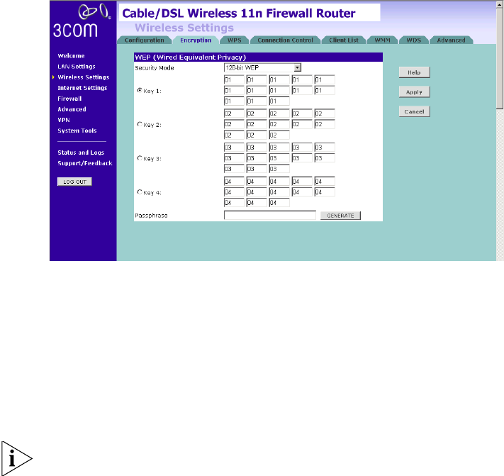
128-bit WEP
WEP is the basic mechanism to transmit your data securely over the
wireless network. Matching encryption keys must be set up on your
Router and wireless client devices to use WEP.
Figure 35 128-bit WEP Screen
To setup 128-bit WEP:
1You can enter the 128-bit WEP key manually:
■enter your WEP key as 13 pairs of hex digits (0-9, A-F).
Or you can generate the 128-bit WEP key automatically:
■enter a memorable passphrase in the Passphrase field, and then
click Generate to generate the hex keys from the passphrase.
The WEP keys on each device on the wireless network must be identical.
In 128-bit WEP mode, only one WEP key can be specified.
2Click Apply.
52 CHAPTER 5: CONFIGURING THE ROUTER
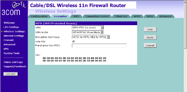
WPA-PSK (no server)
WPA (Wi-Fi Protected Access) provides dynamic key changes and
constitutes the best security solution. If your network does not have a
RADIUS server. Select the no server option.
Figure 36 WPA-PSK (no server) Screen
1Select WPA-PSK (no server) from the WPA drop-down menu.
2Select WPA mode from the drop-down menu, three modes are
supported: WPA, WPA2, and Mixed mode.
3Select Encryption technique from the drop-down menu, four options are
available: TKIP, AES, Auto for WPA AES for WPA2, and AES for both WPA
and WPA2.
4Enter the pre-shared key in the Pre-shared Key (PSK) field. The pre-shared
key is a password, in the form of a word, phrase or series of letters and
numbers. The key must be between 8 and 63 characters long and can
include spaces and symbols. Each client that connects to the network
must use the same key.
5If you want the key that you enter to be shown on the screen as a series
of asterisks (*), then check the Hide PSK checkbox.
6Click Apply.
Wireless Settings 53
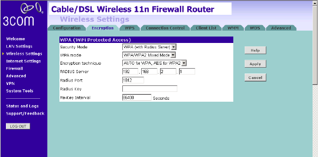
WPA (with RADIUS Server)
WPA (Wi-Fi Protected Access) provides dynamic key changes and
constitutes the best security solution. This function requires that a
RADIUS server is running on the network.
Figure 37 WPA (with RADIUS Server) Screen
1Select WPA with RADIUS server from the Security Mode drop-down
menu.
2Select WPA mode from the drop-down menu, three modes are
supported: WPA, WPA2, and Mixed mode.
3Select Encryption technique from the drop-down menu, four options are
available: TKIP, AES, Auto for WPA AES for WPA2, and AES for both WPA
and WPA2.
4Enter the IP address of the RADIUS server on your network into the
RADIUS Server field.
5Enter the port number that the RADIUS server is operating on in the
RADIUS Port field.
6Enter the key for the RADIUS server in the RADIUS Key field.
7By default, the WPA keys are changed every hour, but if you want to
change this setting, you can do so by specifying the required time in the
Re-key Interval field.
8Click Apply.
54 CHAPTER 5: CONFIGURING THE ROUTER
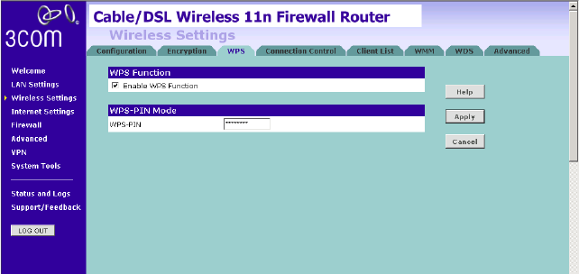
WPS Wireless Provisioning Services (WPS) is a standard for easy and secure
establishment of a wireless home network, created by the Wi-Fi Alliance.
3Com Wireless 11n Cable/DSL firewall Router supports the PIN method.
Check the Enable WPS Function box. The WPS-PIN field will appear.
Figure 38 WPS Screen
Enter the PIN code in the WPS-PIN field. And then click Apply.
Wireless Settings 55
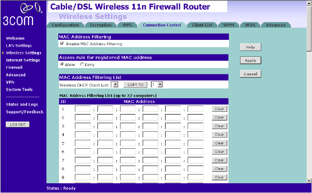
Connection Control This feature is used to filter the clients based on their MAC addresses.
Check the Enable MAC Address Filtering checkbox, the Connection
Control screen will appear.
Figure 39 Connection Control Screen
There are two options available in the Access rule for registered MAC
address field:
■if you click Allow, this means only the MAC addresses registered here
in the list will be allowed to access the Router via wireless link.
■if you click Deny, this means the registered MAC addresses will not be
able to access the Router via wireless link.
Use the MAC Address Filtering List to quickly copy the MAC addresses of
the current wireless clients into the list table. You can define up to 32
MAC addresses to the list.
You can click Clear to delete the current entry in the list.
56 CHAPTER 5: CONFIGURING THE ROUTER
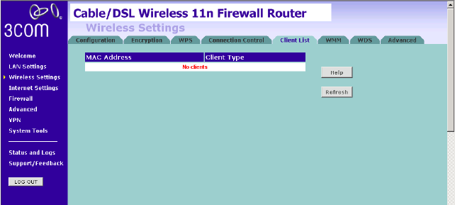
Client List You can view the list of all wireless clients that are connected to the
Router.
Figure 40 Client List Screen
Click Refresh to update the list.
Wireless Settings 57
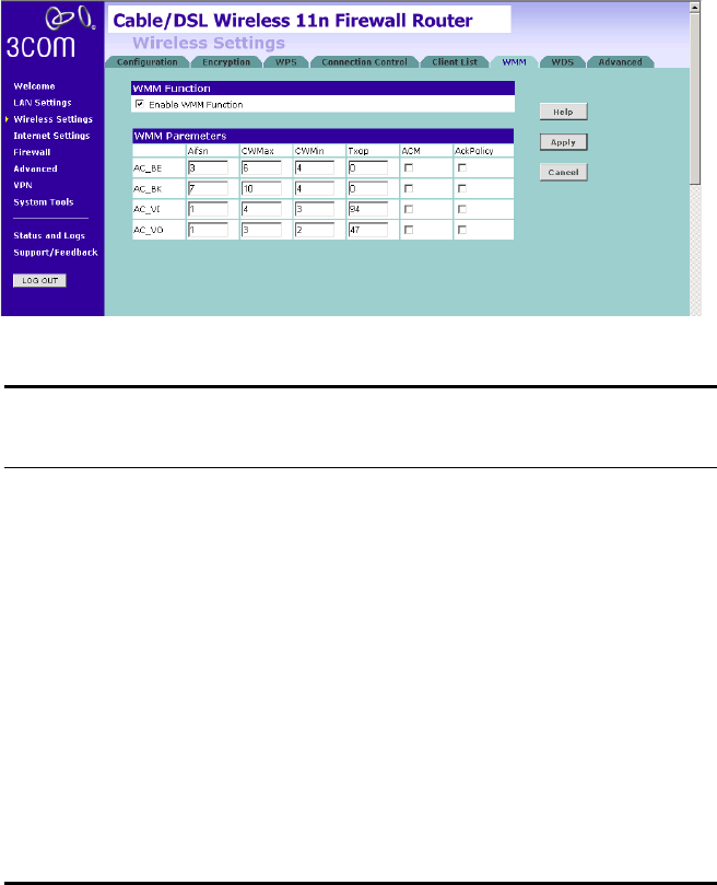
WMM Wireless Multimedia (WMM) mode, which supports devices that meet the
802.11E QBSS standard. WMM uses traffic priority based on the four
ACs; Voice, Video, Best Effort, and Background. The higher the AC
priority, the higher the probability that data is transmitted.
Check the Enable WMM Function box, the WMM parameters table will
appear.
Figure 41 WMM Screen
The following table explains the four access categories:
Access Category WMM
Designation Description
802.1D
Tags
AC_BE (AC0) Best Effort Normal priority, medium
delay and throughput. Data
only affected by long delays.
Data from applications or
devices that lack QoS
capabilities.
0, 3
AC_BK (AC1) Background Lowest priority. Data with no
delay or throughput
requirements, such as bulk
data transfers.
2, 1
AC_VI (AC2) Video High priority, minimum
delay. Time-sensitive data
such as streaming video.
5, 4
AC_VO (AC3) Voice Highest priority, minimum
delay. Time-sensitive data
such as VoIP (Voice over IP)
calls.
7, 6
58 CHAPTER 5: CONFIGURING THE ROUTER
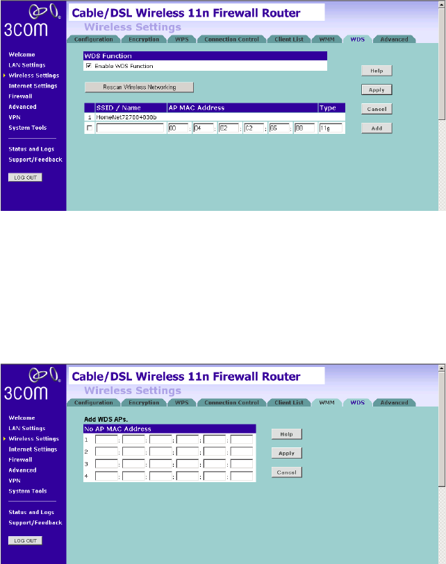
WDS The Router supports WDS (Wireless Distribution System). WDS enables
one or more Access Points to rebroadcast received signals to extend
range and reach, though this can affect the overall throughput of data.
Figure 42 Wireless WDS Settings Screen
1Check the Enable WDS Function checkbox.
2To refresh the list of available access points, click Rescan Wireless
Networking.
3Click Add to add the MAC address of the AP to the list, the add WDS
screen will appear (refer to Figure 43).
Figure 43 Add WDS screen
Enter the MAC address(es) of one or more access points in the AP MAC
Address table, and click Apply.
Wireless Settings 59
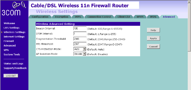
Advanced The Advanced screen allows you to configure detailed settings for your
wireless connection.
Figure 44 Wireless Advanced Setting Screen
There are six parameters that you can configure:
■Beacon Interval: this represents the amount of time between beacon
transmissions.
■DTIM Interval: A DTIM (Delivery Traffic Indication Message) is a
countdown mechanism used to inform your wireless clients of the
next window for listening to broadcast and multicast messages.
■Fragmentation Threshold: this is the maximum size for directed data
packets transmitted. The use of fragmentation can increase the
reliability of frame transmissions. Because of sending smaller frames,
collisions are much less likely to occur.
■RTS Threshold: RTS stands for Request to Send, this parameter
controls what size data packet the low level RF protocol issues to an
RTS packet.
■CTS Protection Mode: CTS stands for Clear to Send. CTS Protection
Mode boosts the Router’s ability to intercept 802.11b/ 802.11g
transmissions. Conversely, CTS Protection Mode decreases
performance. Leave this feature disabled unless you encounter severe
communication difficulties between the Router and your wireless
clients.
■AP Isolation Mode: AP Isolation is a function to prevent wireless clients
connected with the device from communicating with one another.
60 CHAPTER 5: CONFIGURING THE ROUTER
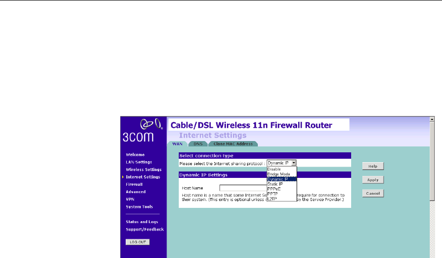
Internet Settings You can configure the settings for your WAN port connection.
WAN This feature is used to configure the parameters for your Internet
connection. The information necessary to complete these screens should
be obtained from your ISP. Check with your ISP first to find out what type
of connection you should choose.
Figure 45 WAN Screen
You should see the first entry already contains information that’s been
configured using the Wizard in the initial setup. If you want to change
that information or set up other connection, click Edit.
There are seven options available for the connection mode:
■Disable — To disable the Internet connection function (see page 61)
■Bridge Mode — RFC1483 Bridged Mode, (see page 61)
■Dynamic IP — Using DHCP for WAN connection (see page 62)
■Static IP — Using fixed IP for WAN connection (see page 63)
■PPPoE — PPP over Ethernet, providing routing for multiple PCs (see
page 64)
■PPTP — Point-to-Point Tunneling Protocol (see page 65)
■L2TP — Layer 2 Tunneling Protocol (see page 66)
Internet Settings 61
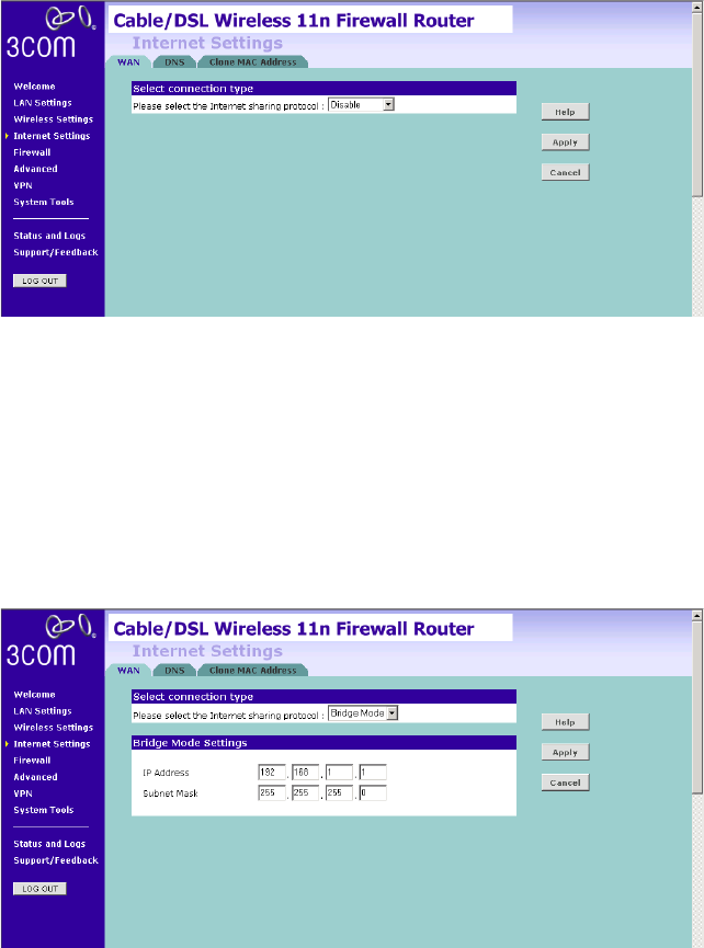
Disable
Selecting this option means that you do not want your Router to connect
to the Internet.
Figure 46 Disable Internet Connection Screen
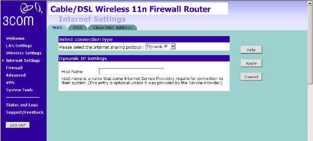
Bridge Mode
If your ISP limits access to the Internet to specific computers, this means
that traffic to/from these computers only will be forwarded. In this case,
Bridge Mode is used to connect to the ISP. The ISP will generally give one
Internet account and limit only one computer to access the Internet.
Check with your ISP to determine if this mode is used for your Internet
connection.
Figure 47 Bridge Mode Screen
Enter the IP address and Subnet mask information.
62 CHAPTER 5: CONFIGURING THE ROUTER
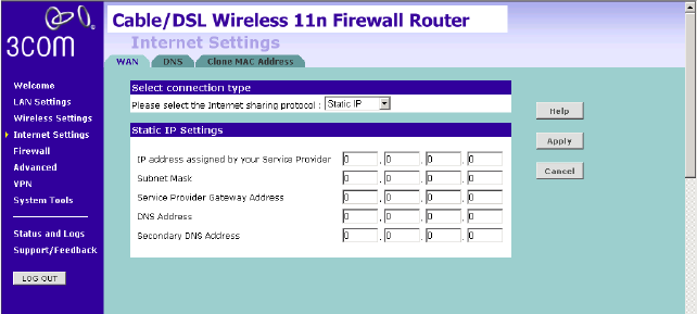
Dynamic IP
You can configure the Router to obtain an IP address automatically from a
DHCP server.
Figure 48 Dynamic IP Screen
1Select Dynamic IP from the Internet sharing protocol drop-down menu.
2If the ISP requires you to input a Host Name, type it in the Host Name
field.
3Click Apply.
Internet Settings 63
Static IP
If your Service Provider has assigned a fixed IP address, enter the assigned
IP address information on the screen.
Figure 49 Static IP Screen
1Select Static IP from the Internet sharing protocol drop-down menu.
2Enter your IP address in the IP address assigned by your service provider
field.
3Enter the subnet mask in the Subnet Mask field.
4Enter the default gateway IP address in the Service Provider Gateway
Address field.
5Enter DNS IP address.
6If there is a secondary DNS, enter the IP address.
7Click Apply.
64 CHAPTER 5: CONFIGURING THE ROUTER
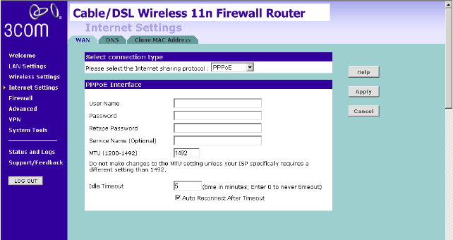
PPPoE
PPP over Ethernet, provides routing for multiple PCs. To configure this
function correctly, you should obtain the information from your ISP.
Figure 50 PPPoE Settings Screen
1Select PPPoE from the Internet sharing protocol drop-down menu.
2Enter the user name assigned to you by your ISP in the Username field.
And enter the password assigned to you by your ISP in the Password field.
Re-enter your password in the Retype Password field.
3The Service Name field is optional.
4Enter the MTU value in the MTU field. Do not make changes to this
setting, unless your ISP specifically requires a different setting other than
1492.
5If you want your Router to automatically disconnect from the Internet
after a period of inactivity, specify a time in the Idle Timeout field. (Enter a
value of 0 to disable this timeout). Check the Auto Reconnect After
Timeout box to automatically re-establish the connection as soon as you
attempt to access the Internet again.
6Click Apply.
Internet Settings 65
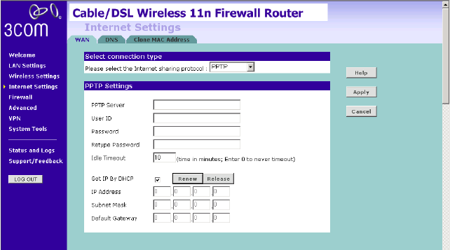
PPTP
If your ISP uses PPTP as the Internet connection protocol, setup the details
on this screen.
Figure 51 PPTP Screen
1Select PPTP from the Internet sharing protocol drop-down menu.
2Enter the PPTP Server information.
3Enter the user ID in the User ID field. And enter the password assigned to
you by your ISP in the Password field. Re-enter your password in the
Retype Password field.
4If you want your Router to automatically disconnect from the Internet
after a period of inactivity, specify a time in the Idle Timeout field. (Enter a
value of 0 to disable this timeout).
5If you receive the IP address from your ISP via DHCP function, check the
Get IP By DHCP box.
6If no DHCP function is used, then enter the IP Address, Subnet Mask, and
Default Gateway information.
7Click Apply.
66 CHAPTER 5: CONFIGURING THE ROUTER
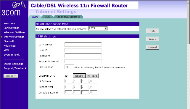
L2TP
If your ISP uses L2TP as the Internet connection protocol, setup the details
on this screen.
Figure 52 L2TP Connection Screen
1Select L2TP from the Internet sharing protocol drop-down menu.
2Enter the L2TP Server information.
3Enter the User ID and Password required by your ISP.
4Retype the password.
5Enter the maximum Idle Timeout for the Internet connection. After this
time has been exceeded the connection will be terminated.
6Check the Get IP By DHCP box to receive IP address from your ISP’s DHCP
function. If this box is not checked, enter the IP address, Subnet mask,
and Default Gateway information.
7Click Apply.
Internet Settings 67
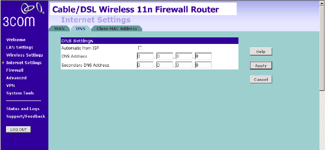
DNS Domain Name Service (or Server) is an Internet service that translates
domain names into IP addresses. Because domain names are alphabetic,
they're easier to remember. The Internet however, is really based on IP
addresses. Every time you use a domain name, a DNS service must
translate the name into the corresponding IP address. For example, the
domain name www.example.com might translate to 198.105.232.4.
Check with your ISP for information on this screen.
Figure 53 DNS Screen
If the DNS information is automatically provided by your ISP every time
you connect to it, check the Automatic from ISP checkbox.
If your ISP provided you with specific DNS addresses to use, enter them
into the appropriate fields on this screen and click Apply.
Many ISPs do not require you to enter this information into the Router. If
you are using a Static IP connection type, you may need to enter a
specific DNS address and secondary DNS address for your connection to
work properly. If your connection type is Dynamic or PPPoE, it is likely that
you do not have to enter a DNS address.
68 CHAPTER 5: CONFIGURING THE ROUTER
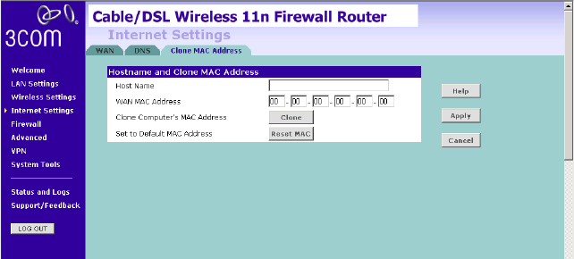
Clone MAC address To configure the Hostname and Clone MAC Address information for your
Router, select Internet Settings, then go to the Clone MAC address tab.
The Hostname and MAC Address screen displays.
Figure 54 Hostname and Clone MAC Address Screen
1Some ISPs require a host name. If your ISP has this requirement, enter the
host name in the Host Name field.
2Three different ways to configure the WAN MAC Address:
■If your ISP requires an assigned MAC address, enter the values in the
WAN MAC address field.
or
■If the computer that you are using is the one that was previously
connected directly to the cable modem, click Clone.
or
■To reset the MAC Address to the default, click Reset MAC.
3Click Apply to save the settings.