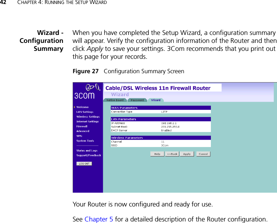
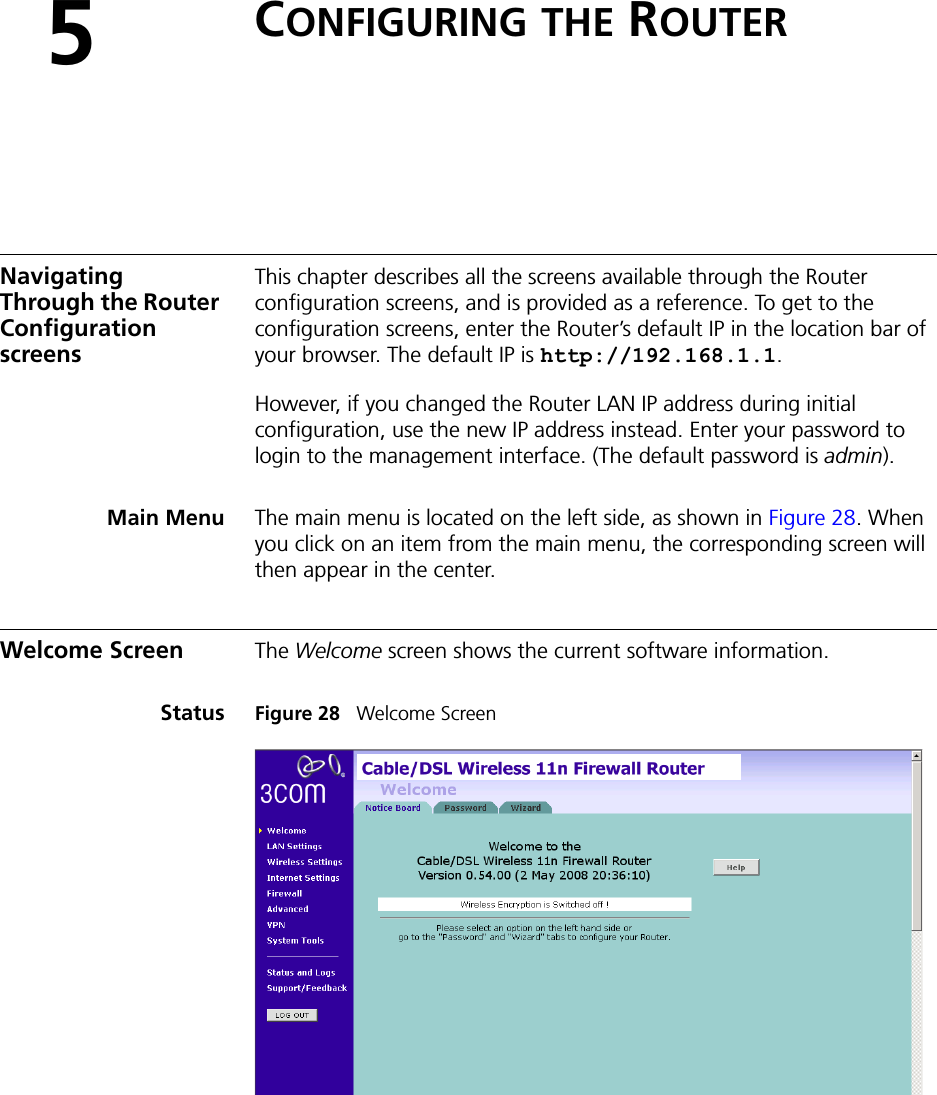
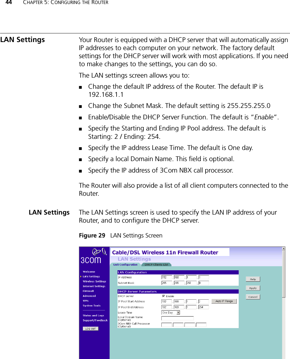
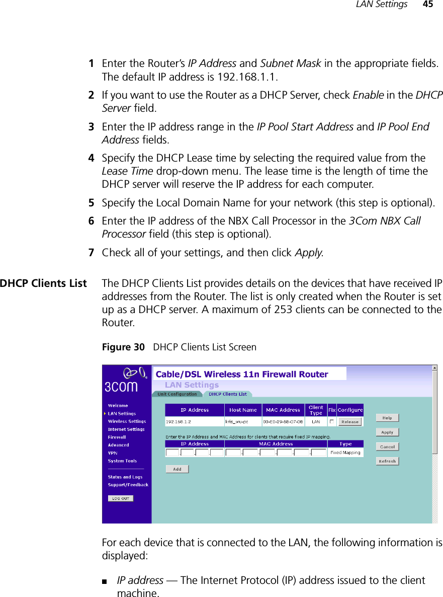
Hewlett Packard Enterprise WL602 DSL Firewall Router User Manual 3com
Hewlett-Packard Company DSL Firewall Router 3com
UserManual.wiki
>
Hewlett Packard Enterprise
>
WL602 User Manual
>
User Manual Part I
Contents
1.
User Manual Part I
2.
User Manual Part II
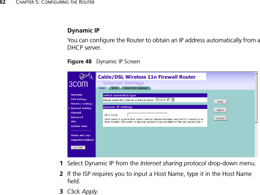
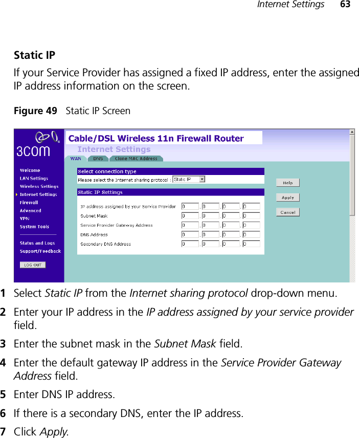
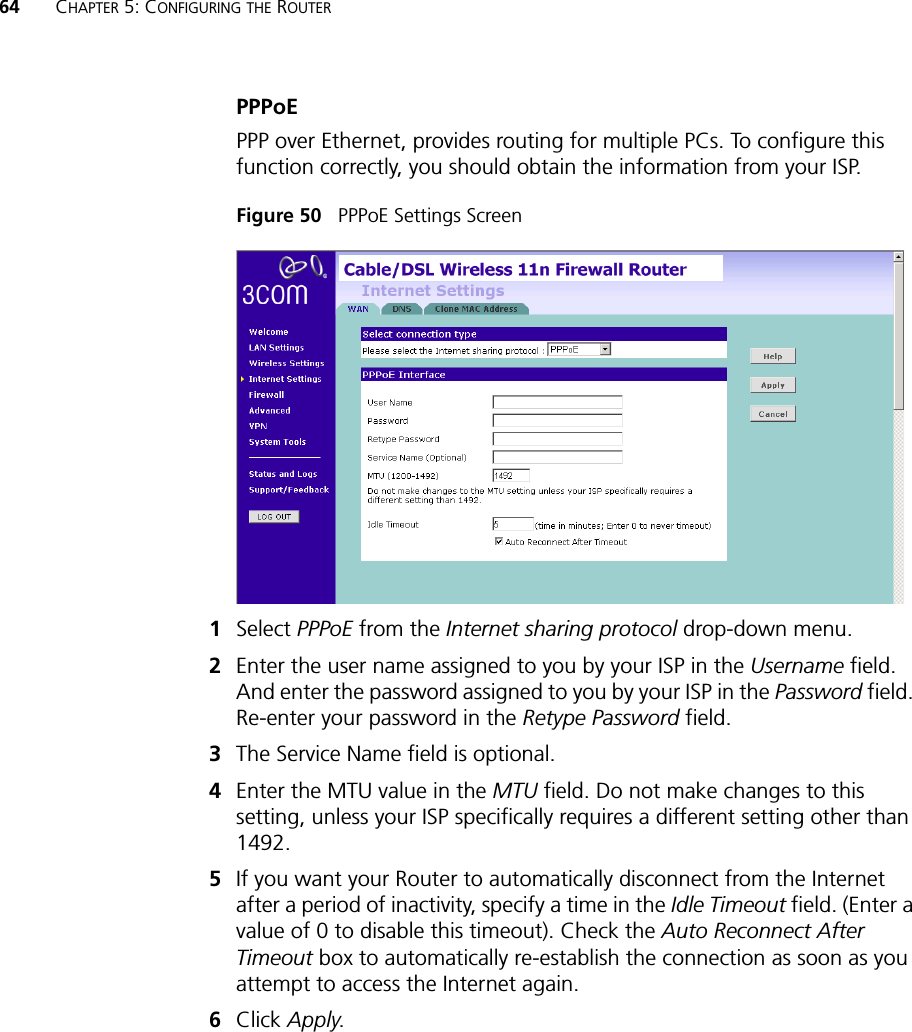
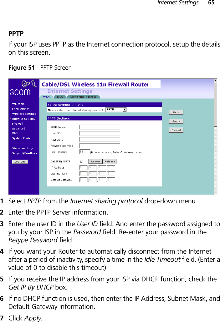
User Manual Part I
Navigation menu
Upload a User Manual
Namespaces
Wiki Guide
HTML
PDF
Info
Views
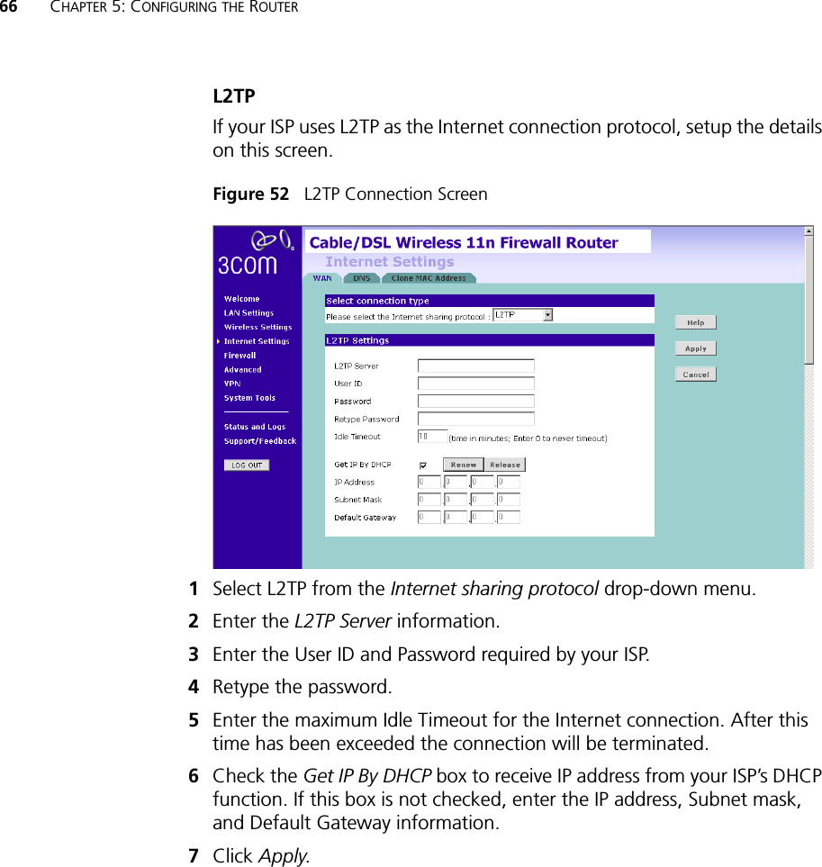
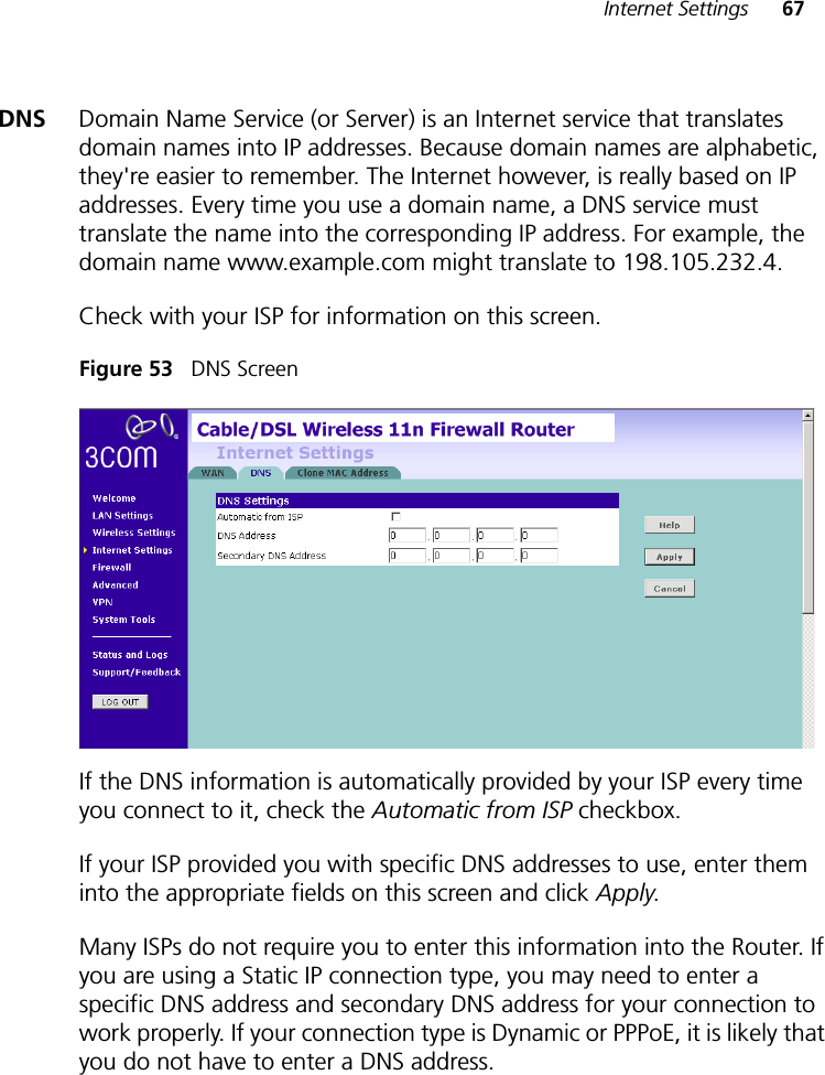
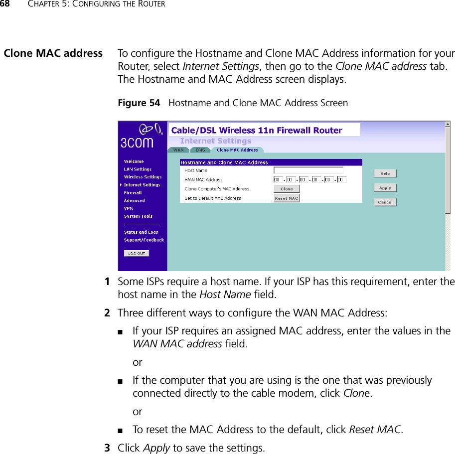
User Manual
Discussion / Help
Navigation