Hewlett Packard Enterprise WL602 DSL Firewall Router User Manual 3com
Hewlett-Packard Company DSL Firewall Router 3com
UserManual.wiki
>
Hewlett Packard Enterprise
>
WL602 User Manual
>
User Manual Part II
Contents
1.
User Manual Part I
2.
User Manual Part II
User Manual Part II
Navigation menu
Upload a User Manual
Namespaces
Wiki Guide
HTML
PDF
Info
Views
User Manual
Discussion / Help
Navigation
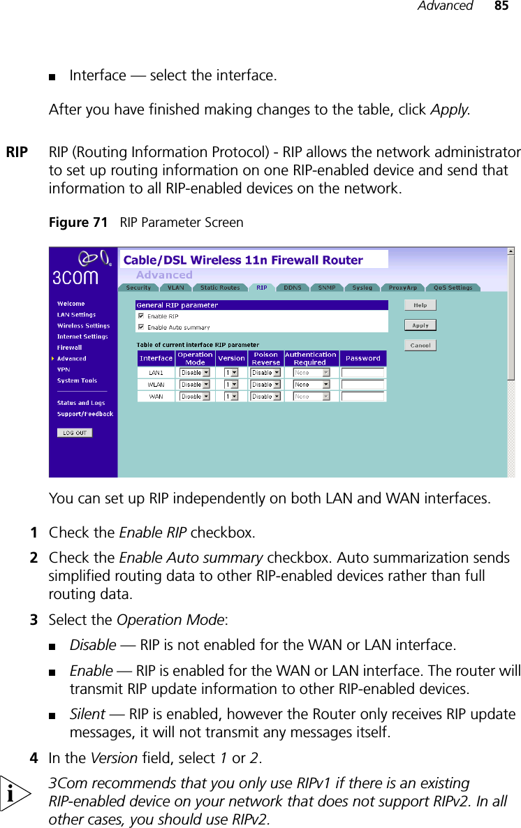
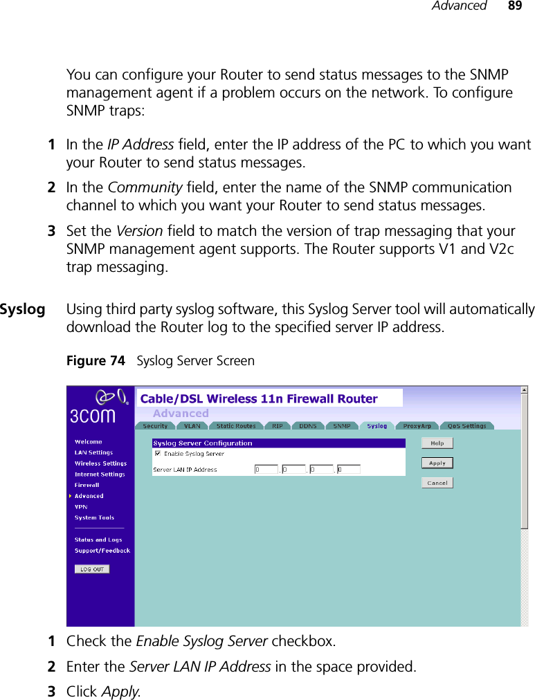

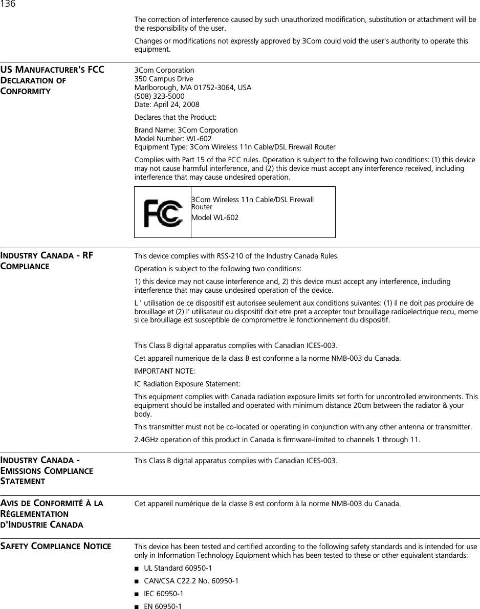
![135REGULATORY NOTICESFor 3Com Wireless 11n Cable/DSL Firewall RouterGENERAL STATEMENTS The 3Com Wireless 11n Cable/DSL Firewall Router (WL-602) must be installed and used in strict accordance with the manufacturer's instructions as described in the user documentation that comes with the product.This product contains encryption. It is unlawful to export out of the U.S. without obtaining a U.S. Export License.This product does not contain any user serviceable components. Any unauthorized product changes or modifications will invalidate 3Com's warranty and all applicable regulatory certifications and approvals.This product can only be used with the supplied antenna(s).EXPOSURE TO RADIO FREQUENCY RADIATIONThis device generates and radiates radio-frequency energy. In order to comply with FCC radio-frequency exposure guidelines for an uncontrolled environment, this equipment must be installed and operated while maintaining a minimum body to antenna distance of 20 cm (approximately 8 in.).The installer of this radio equipment must ensure that the antenna is located or pointed such that it does not emit RF field in excess of Health Canada limits for the general population; consult Safety Code 6, obtainable from Health Canada's website www.hc-sc.gc.ca/rpb.This product must maintain a minimum body to antenna distance of 20 cm. Under these conditions this product will meet the Basic Restriction limits of 1999/519/EC [Council Recommendation of 12 July 1999 on the limitation of exposure of the general public to electromagnetic fields (0 Hz to 300 GHz)].US - RADIO FREQUENCY REQUIREMENTSThis device must not be co-located or operated in conjunction with any other antenna or transmitter.US FEDERAL COMMUNICATIONS COMMISSION (FCC) EMC COMPLIANCE This equipment has been tested and found to comply with the limits for a Class B digital device, pursuant to Part 15 of the FCC Rules. These limits are designed to provide reasonable protection against harmful interference in a residential installation. This equipment generates, uses and can radiate radio frequency energy and, if not installed and used in accordance with the instructions, may cause harmful interference to radio communications. However, there is no guarantee that interference will not occur in a particular installation. If this equipment does cause harmful interference to radio or television reception, which can be determined by turning the equipment off and on, the user is encouraged to try to correct the interference by one of the following measures:■Reorient or relocate the receiving antenna.■Increase the separation between the equipment and receiver.■Connect the equipment into an outlet on a circuit different from that to which the receiver is connected.■Consult the dealer or an experienced radio/TV technician for help.This device complies with Part 15 of the FCC Rules. Operation is subject to the following two conditions: (1) This device may not cause harmful interference, and (2) this device must accept any interference received, including interference that may cause undesired operation.FCC Caution: Any changes or modifications not expressly approved by the party responsible for compliance could void the user's authority to operate this equipment.IMPORTANT NOTE:FCC Radiation Exposure Statement:This equipment complies with FCC radiation exposure limits set forth for an uncontrolled environment. This equipment should be installed and operated with minimum distance 20cm between the radiator & your body.This transmitter must not be co-located or operating in conjunction with any other antenna or transmitter.2.4GHz operation of this product in the U.S.A. is firmware-limited to channels 1 through 11.The user may find the following booklet prepared by the Federal Communications Commission helpful: The Interference HandbookThis booklet is available from the U.S. Government Printing Office, Washington, D.C. 20402. Stock No. 004-000-0034504.3Com is not responsible for any radio or television interference caused by unauthorized modification of the devices included with this 3Com Wireless 11n Cable/DSL Firewall Router (WL-602), or the substitution or attachment of connecting cables and equipment other than specified by 3Com.](https://usermanual.wiki/Hewlett-Packard-Enterprise/WL602.User-Manual-Part-II/User-Guide-951101-Page-67.png)
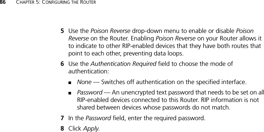
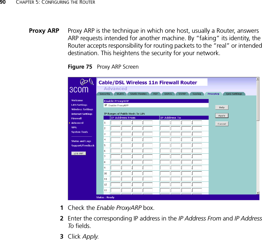
![137EU COMPLIANCEIntended use: DSL/Cable 802.11g/b/n Firewall RouterFor connection to DSL/Cable networksNOTE: To ensure product operation is in compliance with local regulations, select the country in which the product is installed. Refer to 3CRWER300-73 User Guide.For connection to DSL/Cable networksThis equipment may be operated in:AT BE CY CZ DK EE FI FRDE GR HU IE IT LV LT LUMT NL PL PT SK SI ES SEGB IS LI NO CH BG RO TRČesky [Czech]3Com Coporation tímto prohlašuje, ze tento RLAN device je ve shodě se základními pozadavky a dalšími příslušnými ustanoveními směrnice 1999/5/ES.Dansk [Danish]Undertegnede 3Com Corporation erklærer herved, at følgende udstyr RLAN device overholder de væsentlige krav og øvrige relevante krav i direktiv 1999/5/EF.Deutsch [German]Hiermit erklärt 3Com Corporation, dass sich das Gerät RLAN device in Übereinstimmung mit den grundlegenden Anforderungen und den übrigen einschlägigen Bestimmungen der Richtlinie 1999/5/EG befindet.Eesti [Estonian]Käesolevaga kinnitab 3Com Corporation seadme RLAN device vastavust direktiivi 1999/5/EÜ põhinõuetele ja nimetatud direktiivist tulenevatele teistele asjakohastele sätetele.English Hereby, 3Com Corporation, declares that this RLAN device is in compliance with the essential requirements and other relevant provisions of Directive 1999/5/EC.Español [Spanish]Por medio de la presente 3Com Corporation declara que el RLAN device cumple con los requisitos esenciales y cualesquiera otras disposiciones aplicables o exigibles de la Directiva 1999/5/CE.Ελληνική [Greek]ΜΕ ΤΗΝ ΠΑΡΟΥΣΑ 3Com Corporation ΔΗΛΩΝΕΙ ΟΤΙ RLAN device ΣΥΜΜΟΡΦΩΝΕΤΑΙ ΠΡΟΣ ΤΙΣ ΟΥΣΙΩΔΕΙΣ ΑΠΑΙΤΗΣΕΙΣ ΚΑΙ ΤΙΣ ΛΟΙΠΕΣ ΣΧΕΤΙΚΕΣ ΔΙΑΤΑΞΕΙΣ ΤΗΣ ΟΔΗΓΙΑΣ 1999/5/ΕΚ.](https://usermanual.wiki/Hewlett-Packard-Enterprise/WL602.User-Manual-Part-II/User-Guide-951101-Page-69.png)
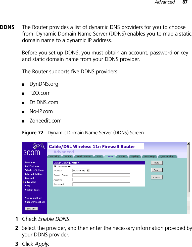
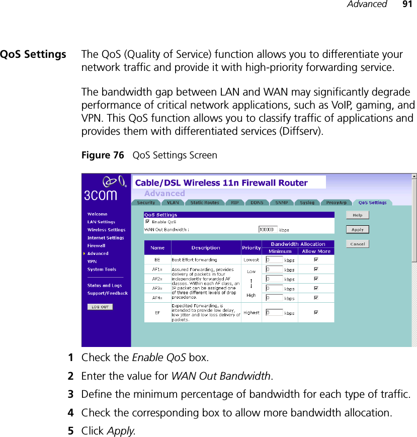
![138A copy of the signed Declaration of Conformity can be downloaded from the Product Support web page for the 3Com Wireless 11n Cable/DSL Firewall Router at http://www.3Com.com. Also available at http://support.3com.com/doc/WL-602_EU_DOC.pdf. Français [French]Par la présente 3Com Corporation déclare que l'appareil RLAN device est conforme aux exigences essentielles et aux autres dispositions pertinentes de la directive 1999/5/CE.Italiano [Italian]Con la presente 3Com Corporation dichiara che questo RLAN device è conforme ai requisiti essenziali ed alle altre disposizioni pertinenti stabilite dalla direttiva 1999/5/CE.Latviski [Latvian]Ar šo 3Com Corporation deklarç, ka RLAN device atbilst Direktîvas 1999/5/EK bûtiskajâm prasîbâm un citiem ar to saistîtajiem noteikumiem.Lietuviø [Lithuanian] Šiuo 3Com Corporation deklaruoja, kad šis RLAN device atitinka esminius reikalavimus ir kitas 1999/5/EB Direktyvos nuostatas.Nederlands [Dutch]Hierbij verklaart 3Com Corporation dat het toestel RLAN device in overeenstemming is met de essentiële eisen en de andere relevante bepalingen van richtlijn 1999/5/EG.Malti [Maltese]Hawnhekk, 3Com Corporation, jiddikjara li dan RLAN device jikkonforma mal-htigijiet essenzjali u ma provvedimenti ohrajn relevanti li hemm fid-Dirrettiva 1999/5/EC.Magyar [Hungarian]Alulírott, 3Com Corporation nyilatkozom, hogy a RLAN device megfelel a vonatkozó alapvetõ követelményeknek és az 1999/5/EC irányelv egyéb elõírásainak.Polski [Polish]Niniejszym 3Com Corporation oświadcza, że RLAN device jest zgodny z zasadniczymi wymogami oraz pozostałymi stosownymi postanowieniami Dyrektywy 1999/5/EC.Português [Portuguese]3Com Corporation declara que este RLAN device está conforme com os requisitos essenciais e outras disposições da Directiva 1999/5/CE.Slovensko [Slovenian]3Com Corporation izjavlja, da je ta RLAN device v skladu z bistvenimi zahtevami in ostalimi relevantnimi določili direktive 1999/5/ES.Slovensky [Slovak]3Com Corporation týmto vyhlasuje, ze RLAN device spĺňa základné poziadavky a všetky príslušné ustanovenia Smernice 1999/5/ES.Suomi [Finnish]3Com Corporation vakuuttaa täten että RLAN device tyyppinen laite on direktiivin 1999/5/EY oleellisten vaatimusten ja sitä koskevien direktiivin muiden ehtojen mukainen.](https://usermanual.wiki/Hewlett-Packard-Enterprise/WL602.User-Manual-Part-II/User-Guide-951101-Page-70.png)