Hi G Tek IGRS40916 DataSeal User Manual ch5
Hi-G-Tek Ltd DataSeal ch5
UserManual.wiki
>
Hi G Tek
>
IGRS40916 User Manual
>
Users Manual 2
Contents
1.
Users Manual Part 1
2.
Users Manual Part 2
3.
Users Manual Part 3
4.
Users Manual Part 4
5.
Users Manual Part 5
6.
Users Manual 1
7.
Users Manual 2
8.
Users Manual 3
9.
Users Manual 4
10.
Users Manual 5
Users Manual 2
Navigation menu
Upload a User Manual
Namespaces
Wiki Guide
HTML
PDF
Info
Views
User Manual
Discussion / Help
Navigation

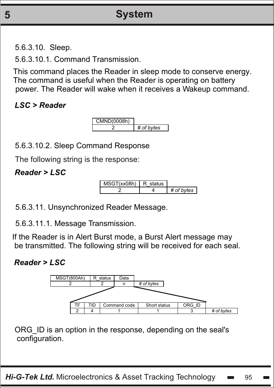
![Hi-G-Tek Ltd. Microelectronics & Asset Tracking Technology 655SystemMCU is the main board of the DataReader.S2 is the slave daughterboard in channel two in the DataReader.Table 5.12.: Reader Parameters: Default Value and Extreme Values.# Parameter Name Default value [unit] Minimum Value Maximum Value Unit Parameter length 1 Version of MCU_firmware - - - 2 Byte 2 Version of S1_firmware - - - 2 Byte 3 RSSI ch2 - - - 1 Byte 4 Reader ID - - - 4 Byte 5 ADI ch2 00000000 - - 4 Byte 6 Department ch2 00 - - 1 Byte 7 Thw ch2 997 390 9766 3.072ms 2 Byte 8 Reader Address 0000 - - 2 Byte 9 Transmitter Power ch2 65 0 100 1 Byte 10 System ch2 00 - - 1 Byte 11 Mode ch2 00 - - 1 Byte 12 Hard Wakeup 3256 390 9766 3.072ms 2 Byte](https://usermanual.wiki/Hi-G-Tek/IGRS40916.Users-Manual-2/User-Guide-264918-Page-17.png)
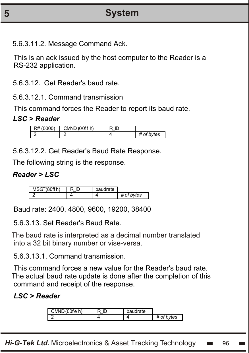
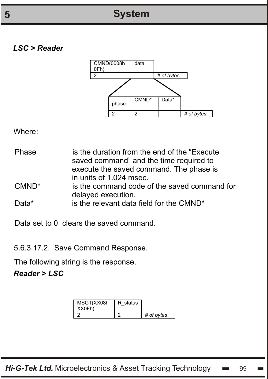
![Hi-G-Tek Ltd. Microelectronics & Asset Tracking Technology 1005System5.6.3.18. Execute Saved Command.5.6.3.18.1. Command Transmission.This is a broadcast command sent to all Readers.There will be no response from any Reader to this command.LSC > Reader CMND(0017h) data 2 4*k # of bytes Reader ID [1] Reader ID [2] Reader ID [k] 4 4 . . . . . . . . . . 4 # of bytes The data field details the Readers by their IDs5.6.3.18.2. Execute Saved Command Response.The following string is the response. There is no response for thiscommand.Reader > LSCSTX #B R# MSGT(XX08h) R_status CRC ETX 1 2 2 2 2 2 1 # of bytes](https://usermanual.wiki/Hi-G-Tek/IGRS40916.Users-Manual-2/User-Guide-264918-Page-52.png)
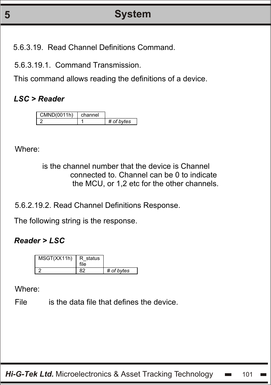
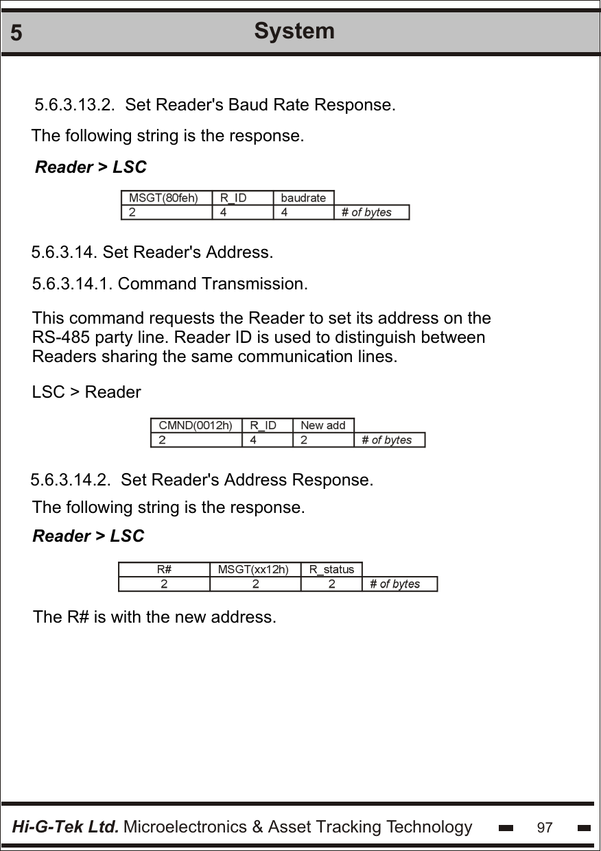
![Hi-G-Tek Ltd. Microelectronics & Asset Tracking Technology 1025SystemFile structure is: Name Size [bytes] 1 Part number 16 2 Serial number 16 3 Hardware version 4 4 Production date 10 5 Production batch number 4 5 Description 32 6 Reserved 45 The file is in ASCII format.](https://usermanual.wiki/Hi-G-Tek/IGRS40916.Users-Manual-2/User-Guide-264918-Page-54.png)