Contents
- 1. Users Manual 1
- 2. Users Manual 2
- 3. Users Manual 3
- 4. Users Manual 5
- 5. Users Manual 4
Users Manual 4

Evaluation
Software
Chapter 7
Hi-G-Tek Ltd. Microelectronics & Asset Tracking Technology 100
Hi-G-Tek Ltd. Microelectronics & Asset Tracking Technology 168
7 Evaluation Software
Check to see if there has been any prior installation of the software.
If a previous installation was detected, it must be removed before
installing the new version. This may be done by clicking the
UNINSTALL.EXE file on the CD-ROM.
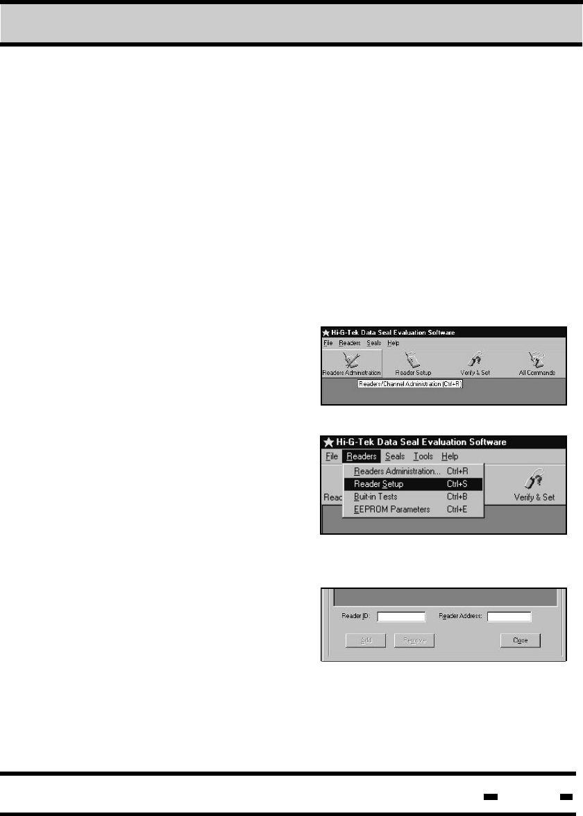
7.2. Communication Setup - Readers Administration.
The Readers Administration
screen may be accessed by
clicking on the Readers menu
button on the top of the screen.
and then on Readers
Administration.
Alternatively, click on the
Readers Administration icon
or type Ctrl+R.
7.2.1. Defining the readers connected.
Reader ID and Reader Address
are used to add/remove readers.
The readers may be connected
using either RS232 or RS485.
The Reader ID is located on the back of the Reader, in barcode
RS232 communication allows
the connection of a single reader
to a PC. As only one user is connected, there is no necessity to
define a specific reader address.
0538443779
7.1. Software installation.
To install the software, insert the CD-ROM disk into your system's
CD-ROM drive. Click on the install icon and follow setup instructions
that appear on the seen
7Evaluation Software
Hi-G-Tek Ltd. Microelectronics & Asset Tracking Technology 169
and numeric format. To add a Reader, insert the Reader ID
and click on the ADD button. To remove a Reader, use the
mouse to mark it and click on the REMOVE button.
RS485 communication allows several readers to be connected
to a single PC. Prior to configuration, the User must decide on
the placement of the readers and in accordance with the layout
decide upon a specific Reader Address for each reader.
0538443779 5
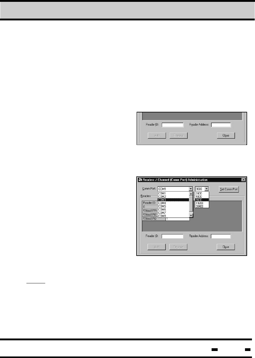
7.2.2. Setting up the communication channel.
In the Readers/Channel
(CommPort) Administration
box, click on the Com. Port
drop down list to define your
communication port.
Click on the Baud Rate drop
down menu list to the right of
the Com. Port drop down list
to define Baud Rate. Once you
have made your selection, click
on the Set Comm Port button.
NOTE: The Baud Rate is determined by the PC's capabilities; the
Reader itself can work at any of the Baud Rates defined in the
drop down list.
7Evaluation Software
Hi-G-Tek Ltd. Microelectronics & Asset Tracking Technology 170
7Evaluation Software
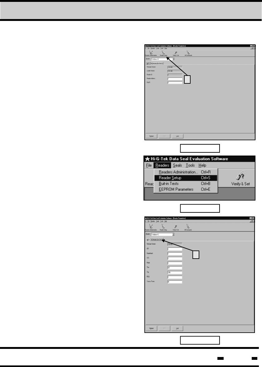
7.3. Readers Setup
To start the Reader Setup, press
on the ”Reader Setup” icon
(Item 1 in Figure 7.1) or select
“Readers” and “Reader Setup as
shown in Figure No. 7.2.
0538443779 5
1
Fig. 7.1
Fig. 7.2
Two groups of parameters are
operated from that screen:
MCU Setup and RF
Modem Setup.
7.3.1. MCU Setup
7.3.2. RF Modem Setup
Firmware Version, Loader
Version, and Reader ID are
Read-Only parameters of the
MCU Setup screen
(Figure 7.1.) Reader Address
is the only parameter that can
be modified.
Fig. 7.3
The first parameter, Firmware
Version is a Read-Only parameter.
All other parameters can be
modified at any time.
After writing the new parameters,
for both the MCU and RF Modem,
click on the “Apply” button.
To get the existing parameters in
the DataReader, select the
appropriate Reader in the
“Reader” box (Item 1 in Figure
7.3). Click on the “Refresh”
button if the parameters are not
updated automatically
1
Hi-G-Tek Ltd. Microelectronics & Asset Tracking Technology 171
7Evaluation Software
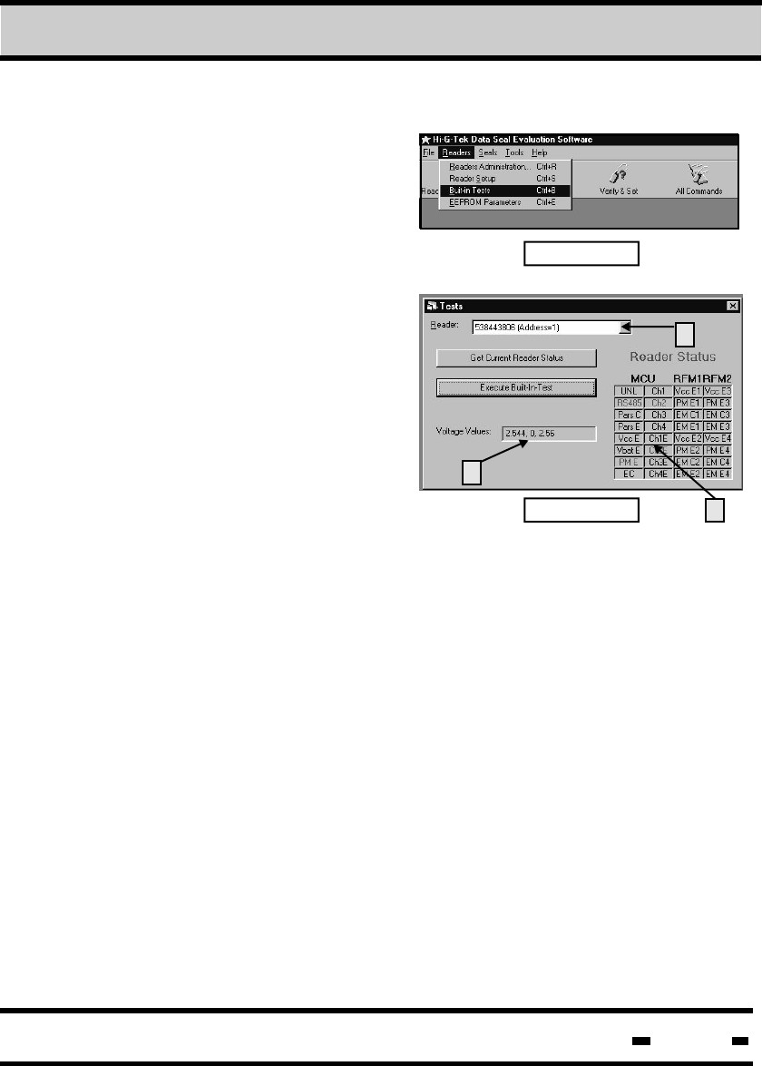
7.4. Built-In Test
In order to perform the test, click
on “Readers” and then “Built-In”
Test as shown in Figure 7.4.
The “Test” window will open
(Figure No. 7.5). Fig. 7.4
Fig. 7.5
Begin the process by selecting
the DataReader to be tested at
the box marked as Item 1 in
Figure 7.5.
To get the results of the last test,
press on the “Get Current Reader
Status” bar. To run a new test,
press on the “Execute Built-In
Test” bar and the new results
will be displayed.
1
3
2
The “Voltage Values” displayed (Item 2 in Figure 7.5) are the actual
values measured in the DataReader: The first value (2.544)
represents the MCU, the second (0) represents the RF Modem 1
(not installed) and the third value (2.56) represents RF Modem 2.
A detailed explanation of the abbreviations in this window (Item 3
in Figure 7.5) is provided hereunder:
Hi-G-Tek Ltd. Microelectronics & Asset Tracking Technology 172
7Evaluation Software
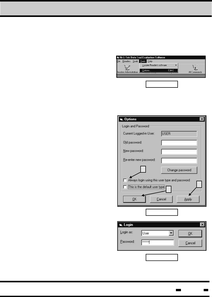
7.5. Login-Password Setup, Password Change
When the program is started for the first time after installation
of the Evaluation Software, it
will open at the lowest
level of authorization. A
password is not required at this
time. Fig. 7.6
To allow only authorized access
using a password, click on “Tools” as shown in Figure 7.6. The
“Options” (Figure 7.7) will open.
Fig. 7.7
The “Options” window is used for
changing the User, Administrator
or Distributor passwords.
Following Setup of the
Evaluation software, the
passwords are:
For User: user
For Administrator: admin
In order to change the password
for any of the three levels of
authorization, key the appropriate
information in the boxes and
press on the “Change Password”
button. If you wish to change the
password of a certain user
(User or Administrator), you must
login as that user.
1
3
2
Fig. 7.8
If you wish to access the
Evaluation Software without
going through the ”Login” window
(Figure 7.8), check the box titled
“Always login using this user type of Password” (Item 1 in
Figure 7.7).

Hi-G-Tek Ltd. Microelectronics & Asset Tracking Technology 173
7Evaluation Software
If you wish the “Login” window to come up each time the Evaluation
Software is activated Password Protection) clear the checkbox
titled ”Always Login Using this user type and password”. If this box
is checked, the “Login “ window will not come up when opening the
Evaluation Software. You will, however, always login as the user type
you selected. If the lower checkbox (Item 2 in Figure 7.7 ) is
checked, the “Login” window will come up with the selected
user type as a default.
Hi-G-Tek Ltd. Microelectronics & Asset Tracking Technology 174
7Evaluation Software
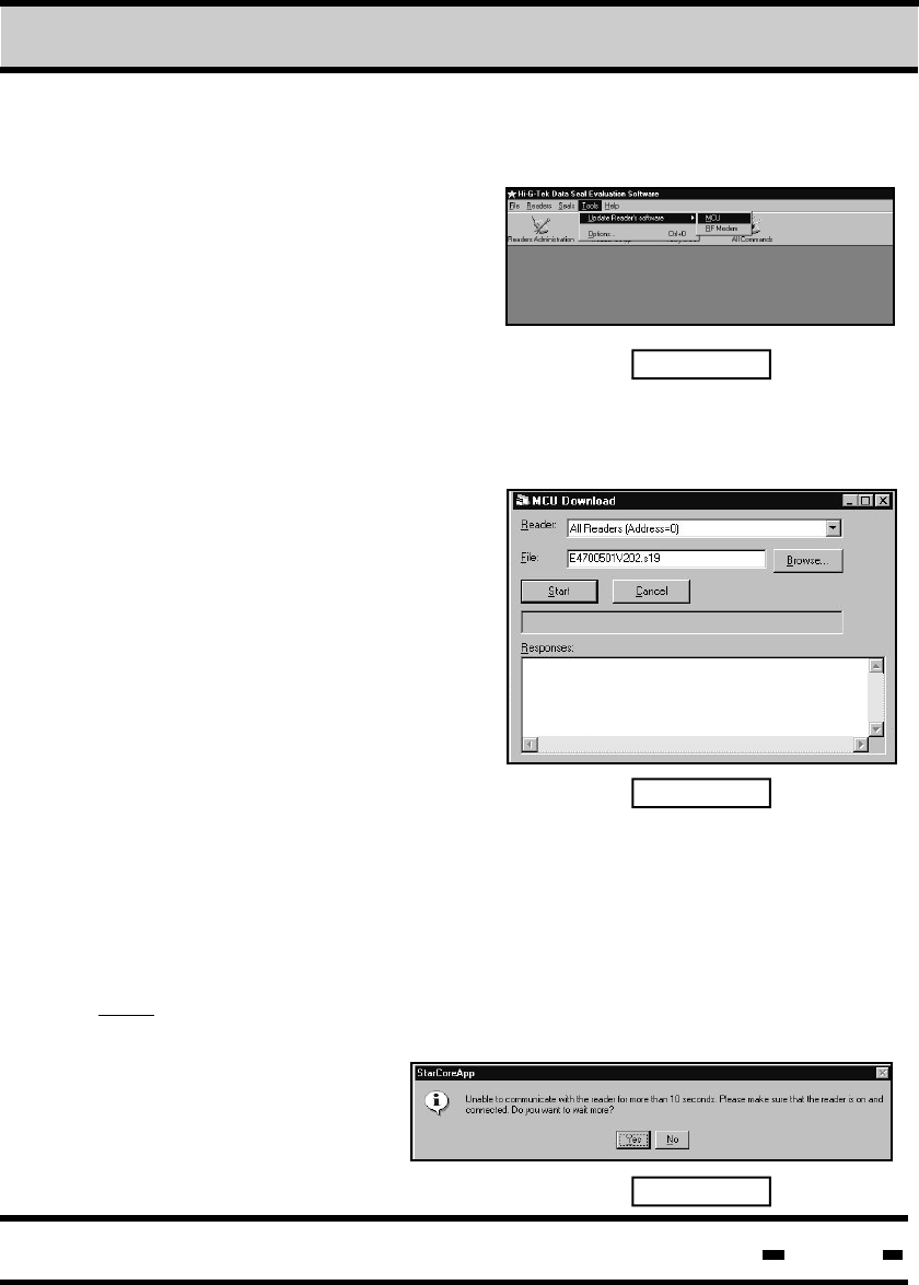
7.6. Download DataReader Software Utility
7.6.1. MCU Software Update
The DataReader's MCU
Software update procedure
is initiated from the
”Hi-G-Tek DataSeal
Evaluation Software” screen.
Fig. 7.9
Select “Tools” in the main menu and “Update Reader's Software”
and mark “MCU” as shown in Figure 7.9
When the “MCU Download”
window comes up, select the
DataReader to get the software
update. The update can be
performed to one DataReader,
chained in the system at a time.
Fig. 7.10
Fig. 7.11
If only one reader is connected
you may choose the “All
Readers (Address=0)” as shown
in Figure 7.10.. If more than one
reader is chained, the address of
the specific reader needs to be
selected. Press on the “Browse” button and mark the file containing
the software update. When the target reader and the file to be
downloaded are presented in the window (as shown in Figure 7.10),
press on the “Start” button to execute the download process.
Note: In the event that communication between the PC and the
DataReader is not established within 10 seconds a message will
come up as shown in
Figure 7.11.
Hi-G-Tek Ltd. Microelectronics & Asset Tracking Technology 175
7Evaluation Software
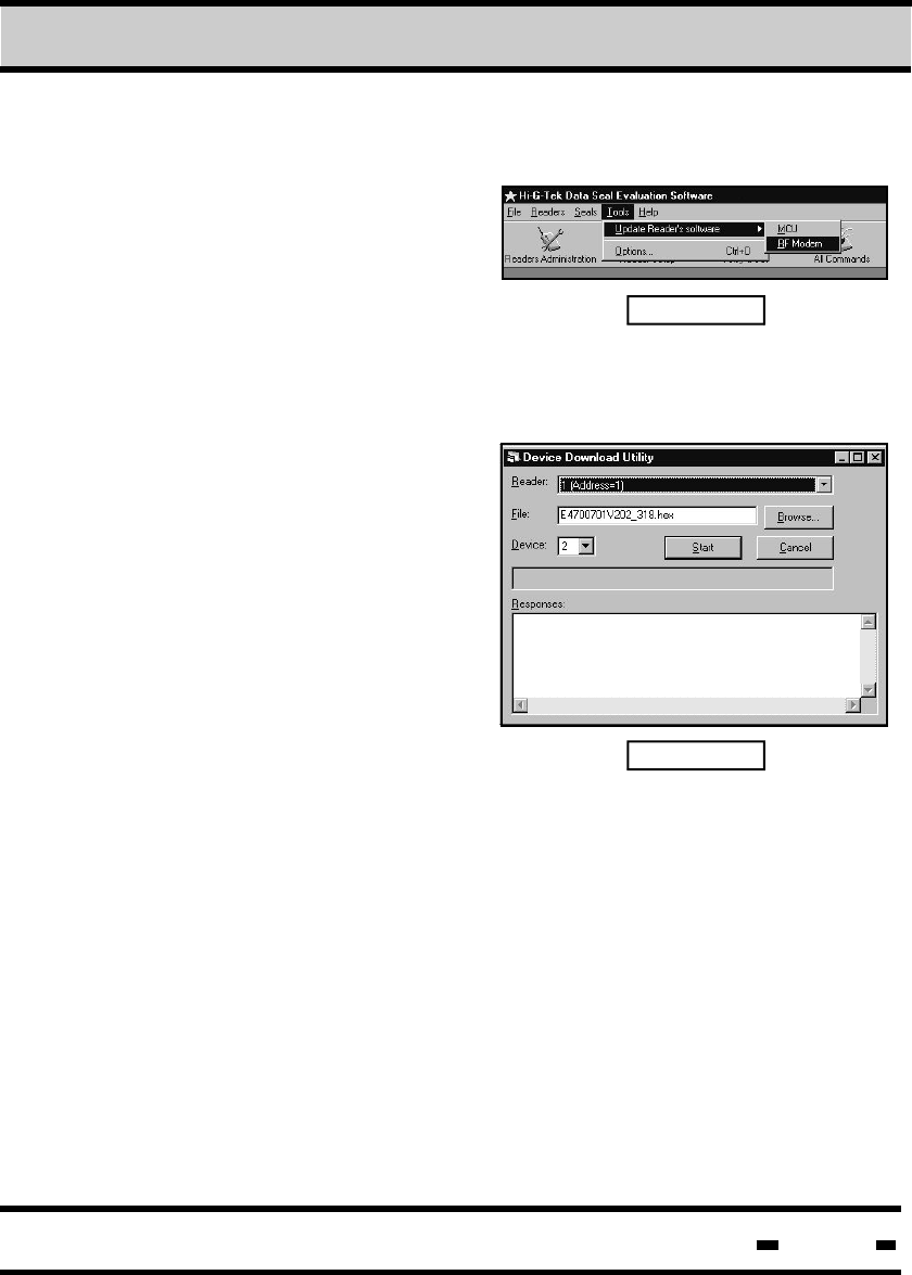
7.6.2. RF Modem Software Update
The DataReader's RF Modem
Software update procedure
is initiated from the ”Hi-G-Tek
DataSeal Evaluation Software”
screen.
Select “Tools” in the main
menu and “Update Reader's Software” and mark “RF Modem”
as shown in Figure 7.12.
Fig. 7.12
Fig. 7.13
When the “Device Download
Utility” window comes up, select
the DataReader which will get
the software update. The update
can be performed to one
DataReader chained in the
system at a time.
If only one reader is connected
you may choose the “All
Readers (Address=0)” as shown
in Figure 7.10. If more than one
reader is chained, the address of
the specific reader needs to be selected (as shown in figure 7.13).
Press on the “Browse” button and mark the file containing the
software update. Press on the “Browse” button and mark the file
containing the software update. Select “Device” in the DataReader
targeted for update: The RF Modem is at location 2.
When the target reader, the file to be downloaded and the location
of the RF Modem are presented in the window (as shown in
Figure 7.13), press on the “Start” button to execute the download
process.
Hi-G-Tek Ltd. Microelectronics & Asset Tracking Technology 176
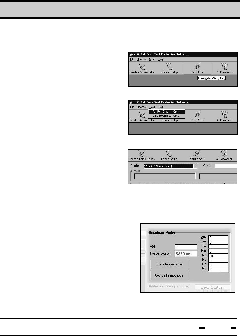
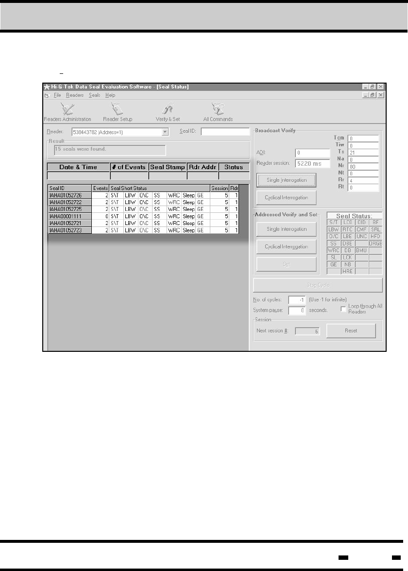
7.7. Performing Verify and Set Cycles
Access the Verify and Set menu
by clicking on the Seals menu
button on the top of the screen,
and then on Verify and Set.
Alternatively, click on the Verify
and Set icon or type Ctrl+I.
7.7.1 Selecting the Reader.
A specific Reader must be
selected prior to the
initialization of a COMMAND
session.
To select a Reader, click on
the Reader drop-down list
and select the appropriate Reader from the list.
7Evaluation Software
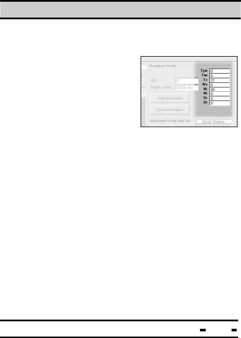
7.7.2 Broadcast Sessions.
In Broadcast Verify mode, the
reader sends interrogation
messages to all the seals.
Hi-G-Tek Ltd. Microelectronics & Asset Tracking Technology 177
7.7.2.1 Setting Sessions Parameters
Time Calibration Message;
this parameter is not currently
in use, and should be set to 0.
Parameter size=1 byte.
Tcm -
Tiw - Time Interlace Window; this
parameter sets the time
between the BMM (Broadcast Master Message) and the
first reply slot. Minimum value=0, maximum value=16000.
Parameter size=2 bytes.
All numbers are represented as
decimal digit values. The Tcm and
Na parameters are not in use, and
their value is 0. An explanation
of the parameters follows below.
Ts -
7Evaluation Software
Na -
Number Assigned; Currently not in use. Value should be 0.
Parameter size=1 byte.
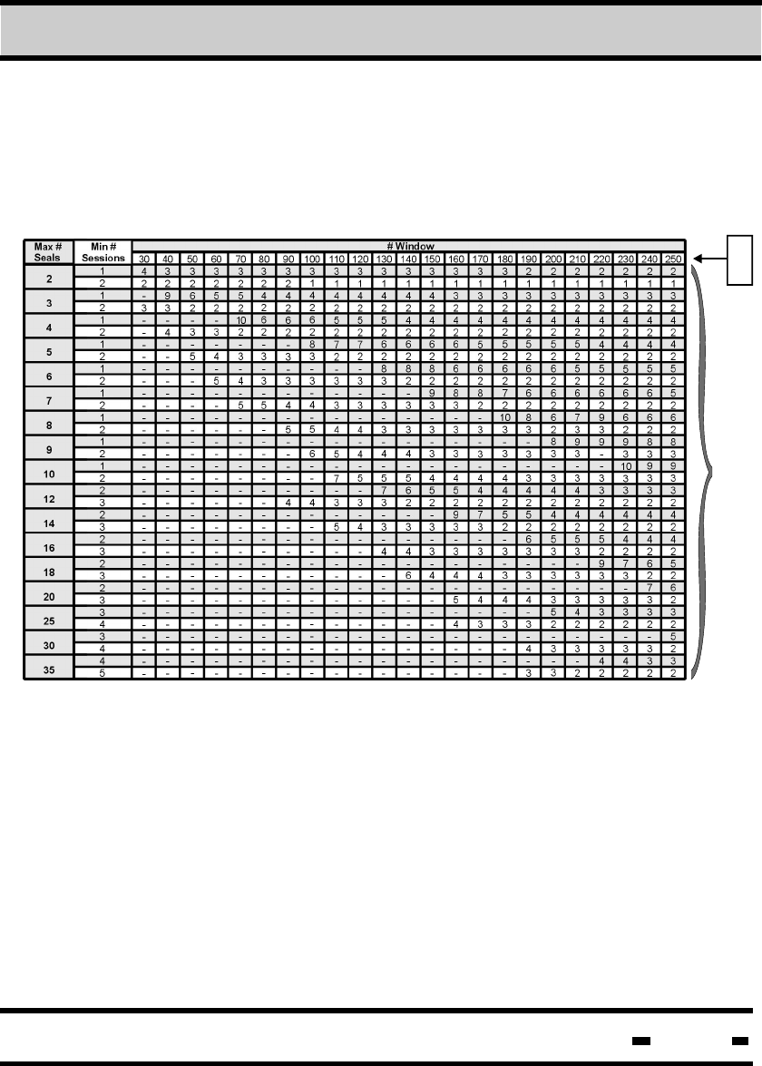
Number Random; Number of random slots. Only a number
from the statistical table may be entered. Parameter size=1 byte.
Nt - Number Tamper; Number of reply slots for the tamper
message. Only a number from the statistical table may be
entered.
Rr - Random Retry; The number of times the seal will send
a transmission. To be set at the User's discretion. Only a
number from the statistical table may be entered.
Nr -
Time slot; Size of reply slot.
Unit size=1.024 ms. This parameter has 4 values which variate
according to the amount of data received. These values are 21,
41, 63, 82. Other values will cause a deviation. Parameter
size=1 byte.
Hi-G-Tek Ltd. Microelectronics & Asset Tracking Technology 178
Retry Tamper; The number of times the seal will send a
tamper message. To be set at the User's discretion. Only a
number from the statistical table may be entered.
Nr, Nt, Rr & Rt Statistical Table
Rr
&
Rt
Nr
&
Nt
Rt -
7Evaluation Software
Hi-G-Tek Ltd. Microelectronics & Asset Tracking Technology 179
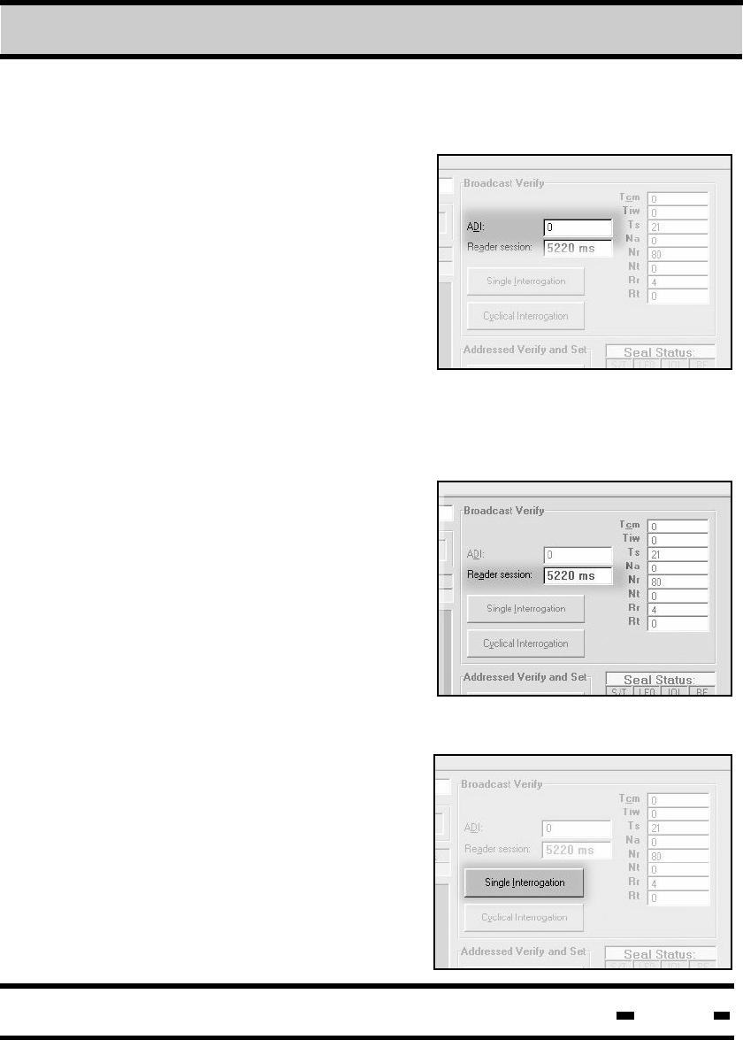
7.7.2.2 ADI Definition
ADI is the Seal Group Identification.
Each seal can have an internal ID
number. ADI defines the seals by
group. All numbers on this screen
are registered in decimal value. The
ADI ranges from a minimum value
of 0 to a maximum value of 64000.
If the number entered in the ADI
text box is "0", all seals respond.
If a specific number is entered, the
seals respond according to their
grouping. See paragraph TBD.
7.7.2.4 Single Session.
Single Interrogation is one reader
session of all seals answering
to a specific definition. This means
that several results may be obtained.
Click on the Single Interrogation
button for a single reader session.
Results of the session appear in a
table to the left of the button (See
section 4.2.6.)
The Reader Session button,
located directly beneath the
ADI window box, defines actual
session time. The system
automatically defines session time
after the User clicks on either the
Single or Cyclical Interrogation
buttons.
7.7.2.3. Reader Session
7Evaluation Software
Hi-G-Tek Ltd. Microelectronics & Asset Tracking Technology 180
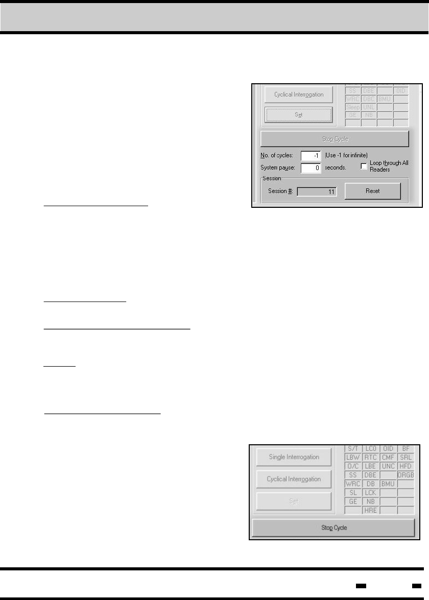
7.7.2.5 Multiple Sessions
Multiple Sessions mode differs from
Single Sessions mode in that the
User can define the number of
cycles of interrogation (up to infinite).
The User can also define the
waiting period between each
session.
The cyclical interogation can be
stopped at any time by clicking on
the Stop Cycle button. Results of the
interrogation appear in a table
to the left of the button (See
section 4.2.6.)
Number of Cycles: Clicking on the
Broadcast Verify Cyclical
Interrogation button when there is a positive number in the Number
of Cycles window box will cause the system to perform that number
of sessions. When Number of Cycles is defined as -1, clicking on
the Cyclical Interrogation button will cause the system to perform
an unlimited number of sessions.
System Pause: This option allows the User to define a pause
between reader sessions.
Loop Through All Readers: When this option is selected, the
System Pause acts as a delay between the various readers.
NOTE: When the Loop Through All Readers option is selected, the
value in the No. of Cycles window box must be greater than the
number of readers defined.
Session # and Reset: The Session # window box shows the
sequential number of the next session. Clicking on the Reset
button resets this counter.
7Evaluation Software
Hi-G-Tek Ltd. Microelectronics & Asset Tracking Technology 181
7.7.2.6 Reading the Results
Results of the single and cyclical interrogations appear in tables to
the left of the interrogation buttons. The information in the table
includes the seal ID, the number of events detected, seal stamp,
seal short status, the session number which is the number of the
session in cyclical interrogation mode and the reader number, the
number of the reader being interrogated.
Results are accumulated and can be stored to disk or printed by
clicking on the FILE menu button located on the upper left portion
of the screen.
7Evaluation Software
Hi-G-Tek Ltd. Microelectronics & Asset Tracking Technology 182
NOTE: To sort the interrogation results by Seal ID number, click on
the Seal ID column header . To sort by session number, click on
the Session column header.
Generally, items marked in red indicate errors. Items in red
appearing in the Seal Short Status field indicate warnings or error
status, while those appearing in gray are normal.
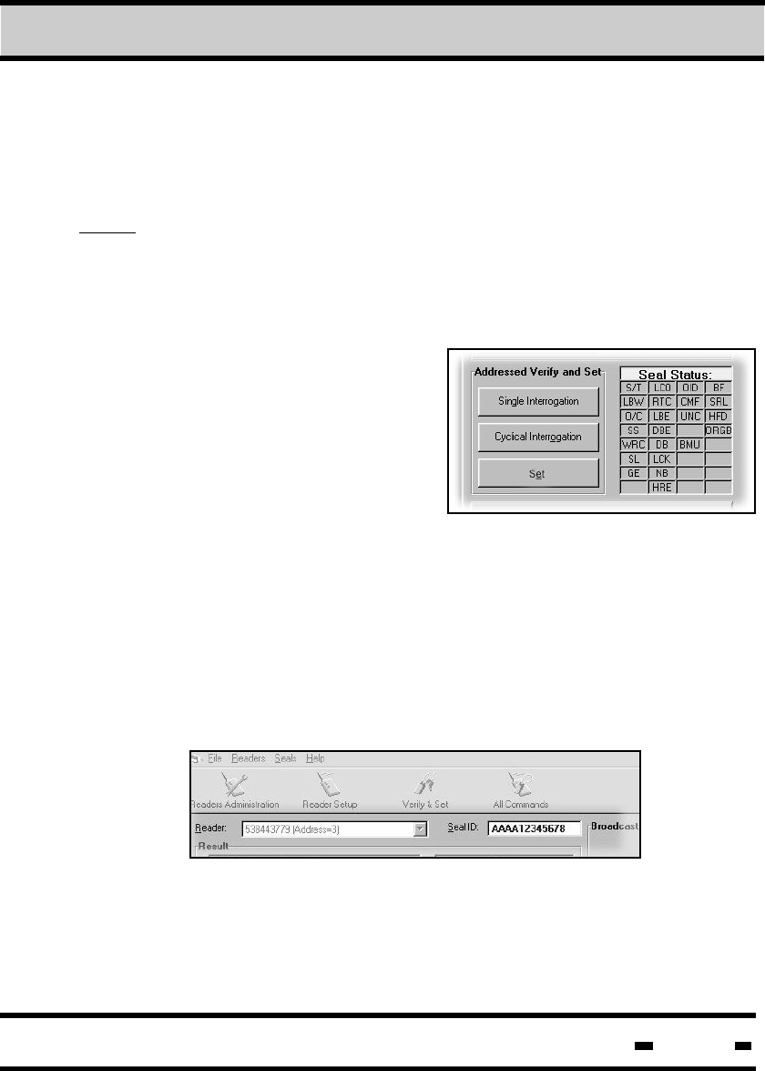
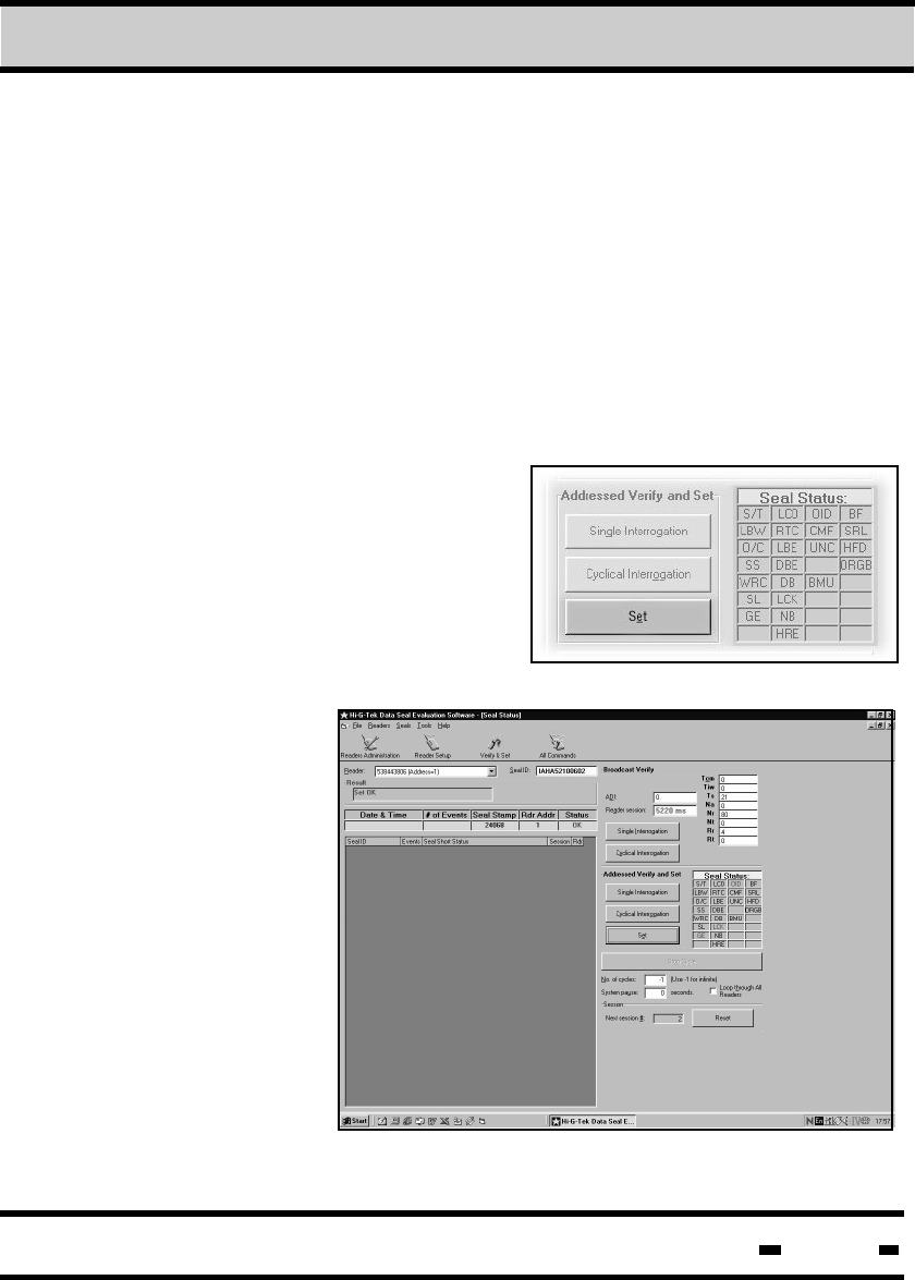
7.7.3 Addressed Verify Sessions
The Addressed Verify Sessions
differ from the Broadcast Verify
sessions in that the reader
sends interrogation messages to
a specified seal. All parameter
definitions described in section
4.2. are relevant here as well.
To initiate an Address Verify Session, enter Reader and Seal ID
data in the relevant windows in the upper portion of the screen
and click on the required mode of interrogation (single or cyclical).
To enter Seal ID automatically, click on the required seal ID that
appears in the result table of a broadcast session.
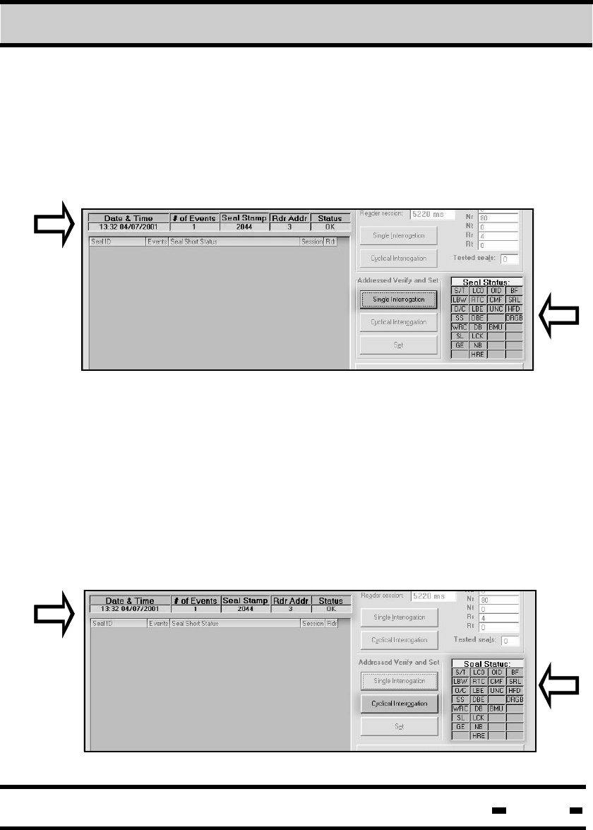
7.7.3.1 Single Session
7Evaluation Software
Hi-G-Tek Ltd. Microelectronics & Asset Tracking Technology 183
For a single interrogation, click on the Single interrogation button.
Results are displayed in the table to the left of the button (1) and
in the Seal Status table (2) to the right of the button. Items appearing
in red in the Seal Status table indicate error status. Items appearing
in black indicate normal status.
1
2
Multiple Sessions mode differs from Single Sessions mode in that
the User can define the number of cycles of interrogation (up to
infinite). Results are displayed in the table to the left of the button (1)
and in the Seal Status table (2) to the right of the button. Items
appearing in red in the Seal Status table indicate error status. Items
appearing in black indicate normal status.
7.7.3.2. Multiple Sessions
1
7Evaluation Software
2

Hi-G-Tek Ltd. Microelectronics & Asset Tracking Technology 184
Number of Cycles: Clicking on the Addressed Verify and Set
Interrogation button when there is a positive number in the Number
of Cycles window box will cause the system to perform that number
of sessions. When Number of Cycles is defined as -1, clicking on
the Cyclical Interrogation button will cause the system to perform
an unlimited number of sessions.
System Pause: This option allows the User to define a pause
between reader sessions.
Loop Through All Readers: When this option is selected, the
System Pause acts as a delay between the various readers.
NOTE: When the Loop Through All Readers option is selected, the
value in the No. of Cycles window box must be greater than the
number of readers interrogated.
Session # and Reset: The Session # and Reset options are not
operational in multiple session mode. The system will stop,
however,If a number has been entered in the Number of Cycles
field.
The cyclical interogation can be stopped at any time by clicking on
the Stop Cycle button. Results of the interrogation are displayed in
the Seal Status table at the right of the button, and in the table to
the left of the button.
7Evaluation Software
Hi-G-Tek Ltd. Microelectronics & Asset Tracking Technology 185
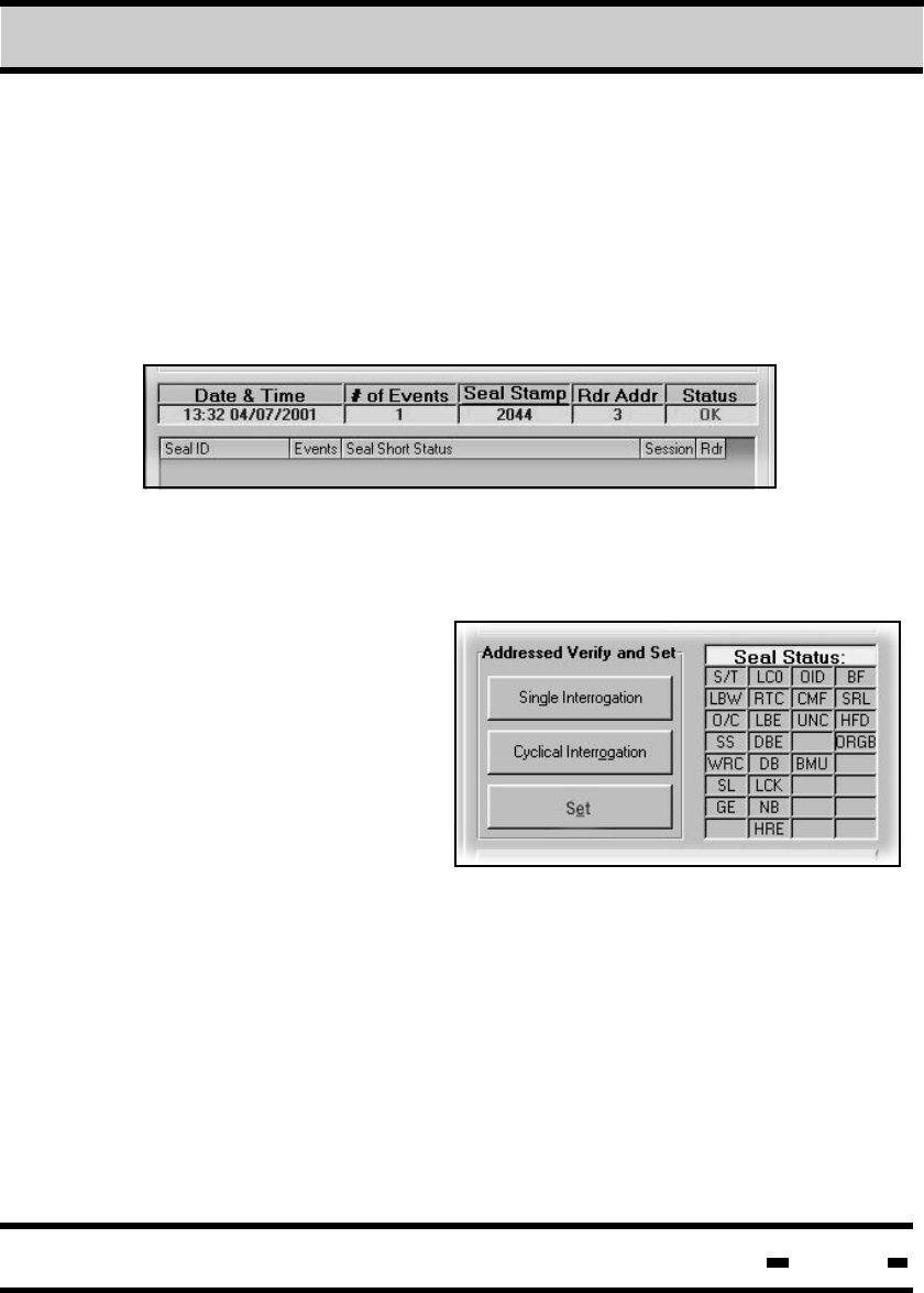
7.7.3.3. Reading the Results
After interrogation the following results are received:
a) In the main information table:
Date and Time, Number of Events, Seal Stamp,
Reader Address and Seal Status.
b) In the Seal Status Table to the right of the buttons. Status events
with detected errors are marked in red. Events marked in black
are normal.
RTC - Real time clock error
LBE - Low bat error
DBE - Data base error
DBC - Data base corrupted
LCK - Locked
NB - New battery
IOD - Illegal org ID
CMF - Command failure
S/T - Set or tamper
LBW - Low battery warning
O/C - Open/close
SS - Suspended set
WRC - Wire change
SL - Deep sleep mode
GE - General Error
LCO - Life counter = 0
7Evaluation Software
Hi-G-Tek Ltd. Microelectronics & Asset Tracking Technology 186
UNC - Unrecognized Command
BMU - Burst Mode Unsynchronic
BF - Buffer Full
SRL - Scroll Event
HFD - High frequency disabled
ORGB - Org ID disabled
7.7.4 SET Sessions
A SET sesion is used to reset
and arm a seal. A SET session
can only be applied to a pre-
defined seal. To initiate a SET
Session, ensure that Seal Wire
has been connected. Enter
Reader and Seal ID data in the
relevant windows
in the upper
portion of the
screen and click
on the SET button.
Any change in the
seal status will
dispay a TAMP
message.
7Evaluation Software
Hi-G-Tek Ltd. Microelectronics & Asset Tracking Technology 187
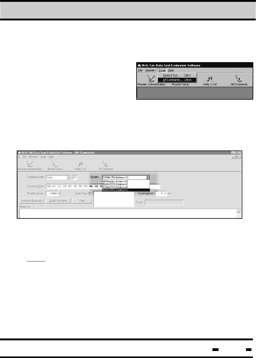
7.8. Performing General Commands Cycles.
The main function of the
General Commands Cycles is
to get acquainted with the
system. Access the General
Commands screen by clicking
on ALL COMMANDS located
in the Seal drop down menu. Alternatively, click on the ALL
COMMANDS icon or type CNTRL+A.
7.8.1. Selecting a Reader
Select a reader by clicking on the reader drop down list. Click
on the appropriate reader to select it.
NOTE: Parameters appearing in the Command Data window may
be changed by the User according to the data in the statistical table.
7Evaluation Software
Hi-G-Tek Ltd. Microelectronics & Asset Tracking Technology 188
7.8.3. Defining Seals
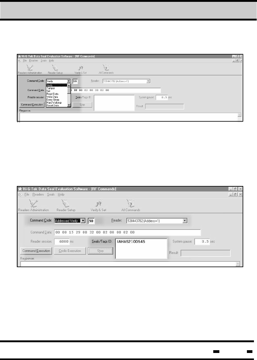
7.8.2. Selecting a Command
Select a command by clicking on the Command Code drop down
list, and then by clicking on the appropriate command. Parameters
of the selected command appear in the Command Data window
below. The number appearing in the fiels to the right of the
Command Code field is the OPCODE>
A seal is defined by typing seal ID in the Seals/Tags ID window.
The Seal ID number can be found in numeric and barcode
format on the seal.
7Evaluation Software
Hi-G-Tek Ltd. Microelectronics & Asset Tracking Technology 189
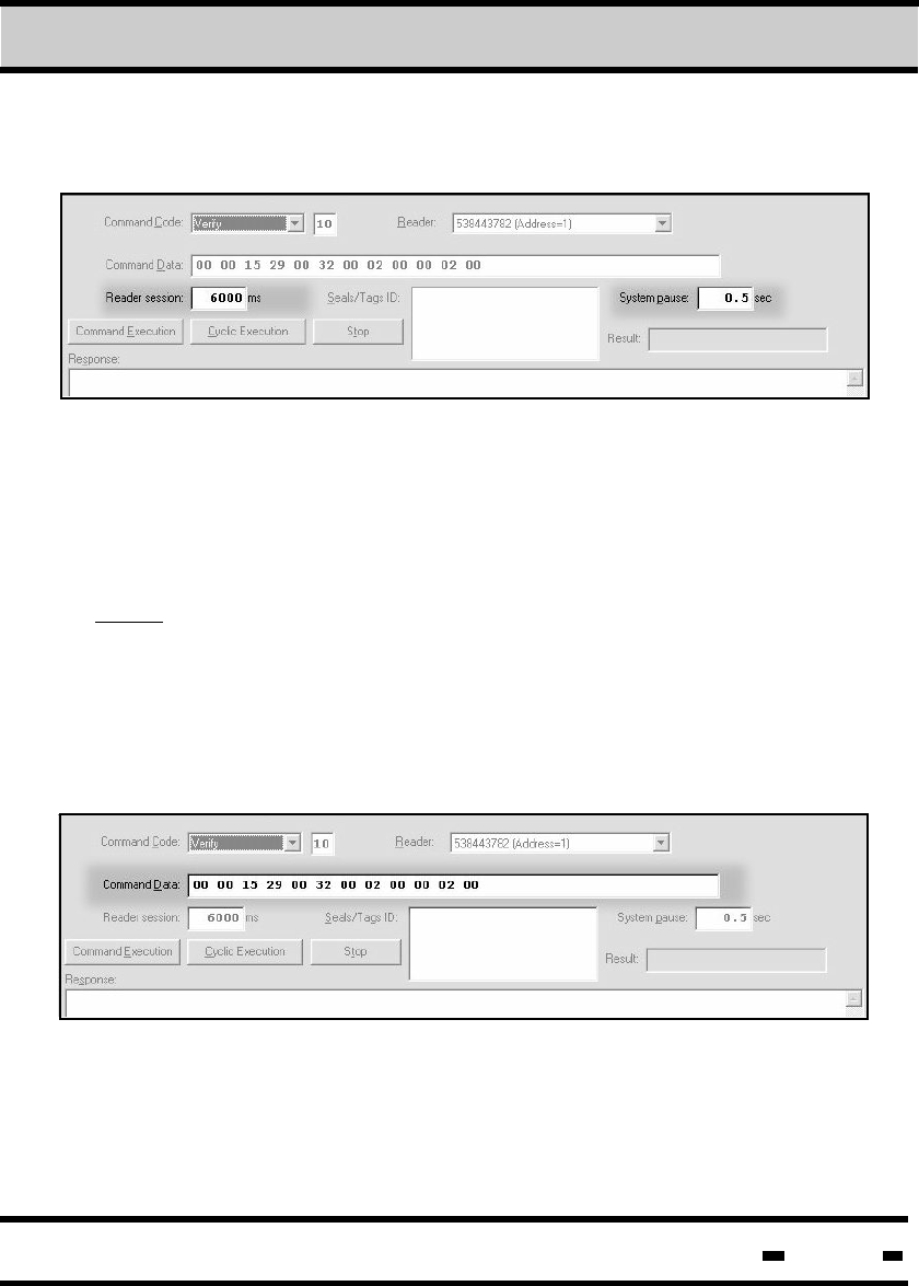
7.8.4. Setting the System Session Duration
7.8.5. Setting the Command Parameters
System session duration is automatically set by the system upon
initiation. This may be changed by the User in accordance with
specific requirements.
Command parameters are initially determined by the system, and
appear in HEX format in the Command Data window box after a
Command Code has been selected. If necessary, parameters may
be changed in accordance with the User's requirements.
NOTE: Time settings differ according to parameters of the chosen
command. If the parameters are changed, the User should try to
initiate a session using the default settings. If a Command Fail
message is received, the time should be increased. For details
regarding calculation of time setting, see paragraph 5.10.
System pause is the pause between sessions when the system is
in cyclic mode. This may also be set by the user.
7Evaluation Software
Hi-G-Tek Ltd. Microelectronics & Asset Tracking Technology 190
7.8.6. Single or Continuous Settings
Similar to Single and Cyclic Interrogation, Command Execution
and Cyclic Execution perform single and cyclic execution of the
chosen command. Results appear in the box below the buttons.
To stop a Cyclic Execution session, click on the Stop button.
7Evaluation Software
Hi-G-Tek Ltd. Microelectronics & Asset Tracking Technology 191
7.8.7 Commands
7.8.7.1. Verify Command
Clicking on one of the commands in the Command Code drop
down list initializes that command's Command Screen. Following
is a description of the commands:
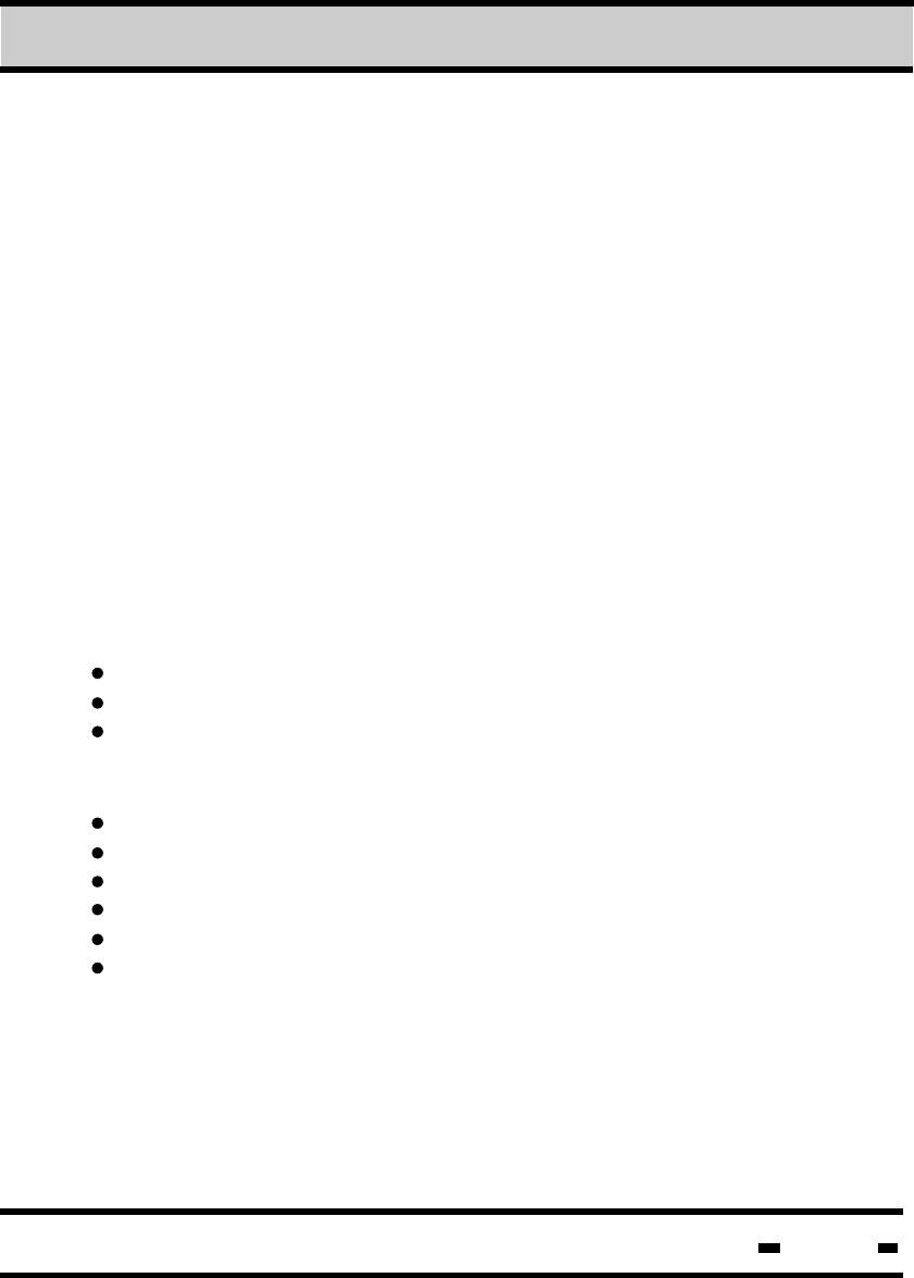
The VERIFY command is used to seek all the seals located in
the area that answer the following conditions:
- ORG ID
- ADI
- Department
An explanation of the command parameters can be found in
chapter 5.
The significant parameters which accompany the command in the
following example are: (A prior requisite is that the Tiw has been reset)
Number of windows: NR=32 hex
Size of seal transmission window: Ts=29 hex
Number of seal re-transmissions: Rr=02 hex
Parameters required for reading are:
Short Status
Date & Time
Number of Events
Version of Firmware
Long Status
Seal Stamp
Table 5.4 in chapter 5 defines the Bit mask required for these
parameters. Bit Mask=d360 hex.
7Evaluation Software
Hi-G-Tek Ltd. Microelectronics & Asset Tracking Technology 192
The initial response string always includes information regarding
Number of Bytes, Seal ID and Message Type. A seal may receive
a number of identical responses depending on the number of re-
transmissions (Rr) defined and the results of conflicts with other
seals..
Number of Bytes=19
Seal ID=48481010102f
MSGT=10
Short Status=00 hex
Date & Time=33099301 hex
Number of Events=01 hex
Version of Firmware=0203 hex
Long Status=00000000 hex
Org_ID=123400
Seal Stamp=701d hex
Explanation of Results:
NOTE: If the Global Parameter is activated, Reader access to some
of the parameters will be blocked (see section 5.4).
7Evaluation Software
193
Hi-G-Tek Ltd. Microelectronics & Asset Tracking Technology
7Evaluation Software
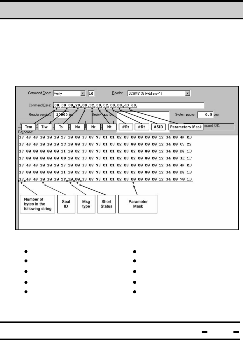
7.8.7.2. Tamper Command
7.8.7.3. Addressed Verify
The TAMPER command is used to find all seals in the Reader's
range which indicate a TAMPER status. Command definition and
method of execution are identical to those of the VERIFY
command described in section 7.8.7.1.
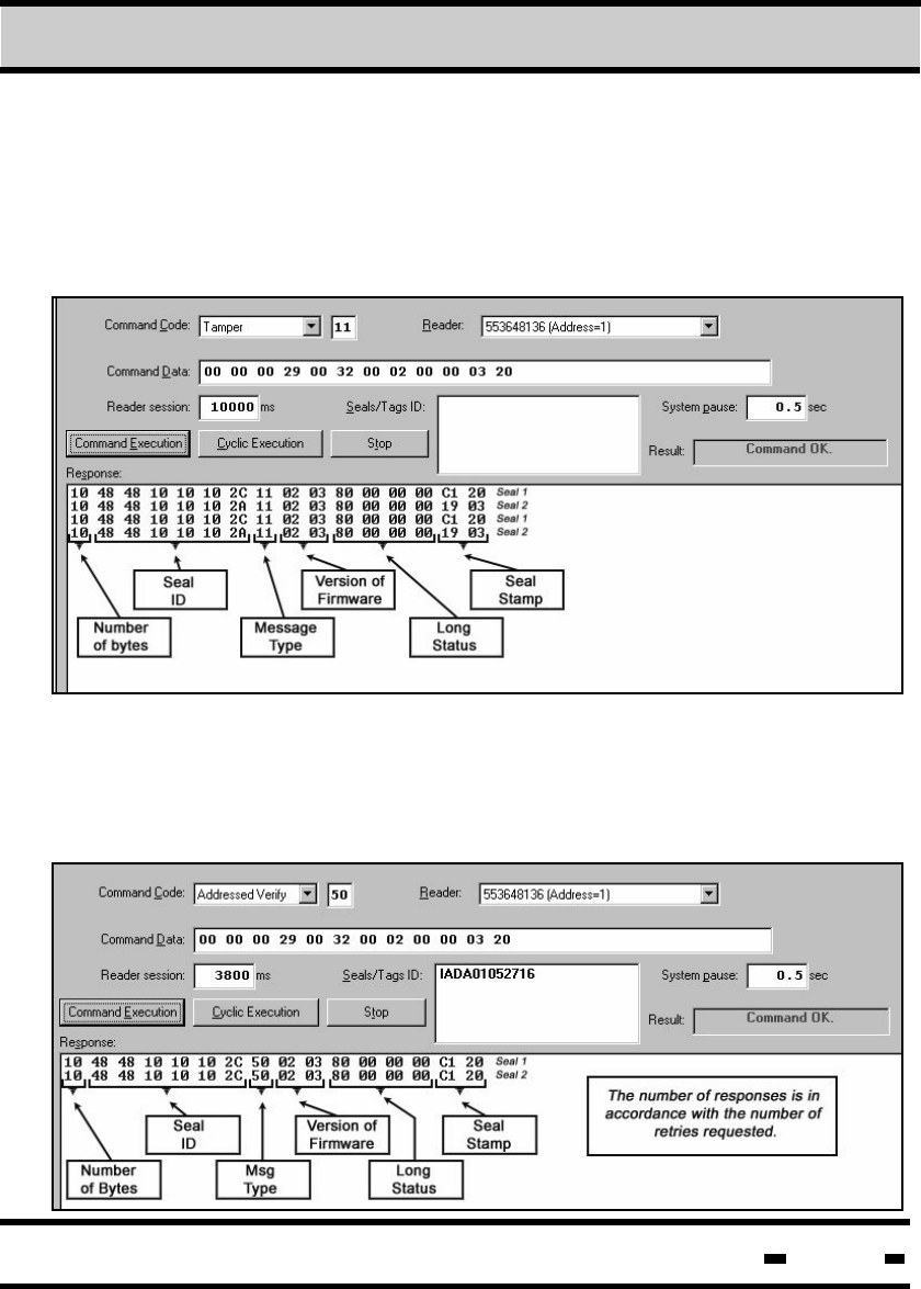
The ADDRESSED VERIFY command is a VERIFY command for
a specific seal. In order to affect this command, the Seal ID must
be entered into the required field. All other parameters are identical
to those of the VERIFY command described in section 7.8.7.1.
Hi-G-Tek Ltd. Microelectronics & Asset Tracking Technology 194
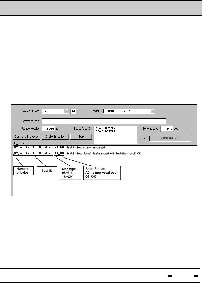
7.8.7.4. SET
The SET command is used to arm or set one or several seals.
Up to eight seals can be set in a single session. The SET
command cannot be activated if the Seal Wire is not
connected to the seal
Initiation of the SET command deletes all events stored in the
EVENTS MEMORY. An additional explanation of this feature
can be found in the Hi-G-TEK DataTerminal user manual.
Seal status will be indicated as closed (OK) or open (FAIL). An
example of this can be seen in the RESPONSE window of the
illustration below: The first row indicates an open seal and
TAMPER status, and therefore a FAIL result, while the second
row indicates a closed seal, status OK.
7Evaluation Software
Hi-G-Tek Ltd. Microelectronics & Asset Tracking Technology 195
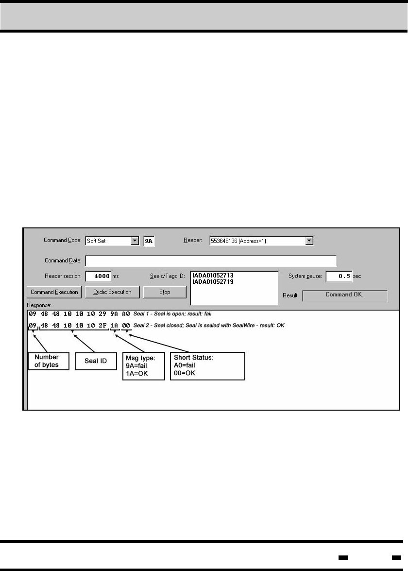
7.8.7.5. Soft SET
Similar to the SET command, the SOFT SET command is used
to arm or set one or several seals. Up to eight seals can be set
in a single session. The SOFT SET command cannot be
activated if the Seal Wire is not connected to the seal.
Seal status will be indicated as closed (OK) or open (FAIL). An
example of this can be seen in the RESPONSE window of the
illustration below: The first row indicates an open seal and
TAMPER status, and therefore a FAIL result, while the second
row indicates a closed seal, status OK.
The main difference between the SOFT SET and SET commands
is that the SOFT SET command does not delete previous events
stored in the EVENTS MEMORY.
7Evaluation Software
Hi-G-Tek Ltd. Microelectronics & Asset Tracking Technology 196
7Evaluation Software
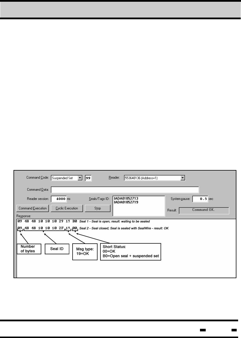
7.8.7.6. Suspended SET
Similar to the SET and SOFT SET commands, SUSPENDED
SET is used to arm or set one or several seals. Up to eight
seals can be set in a single session. The SUSPENDED SET
command can only be initiated if the SealWire has not been
connected to the seal.
Seal status will be indicated as closed (OK) or open + suspended
set. An example of this can be seen in the RESPONSE window of
the illustration below: The first row indicates an open seal that has
not been sealed with Seal Wire. The status shows the seal is open
+ suspended set, waiting to be sealed.
The second row indicates a closed seal, status OK.
In the event of a FAIL status response, the message type response
is "99".
Hi-G-Tek Ltd. Microelectronics & Asset Tracking Technology 197
7Evaluation Software
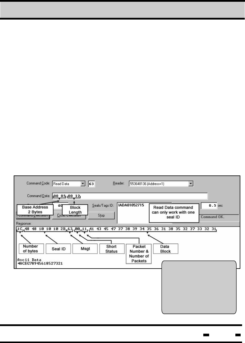
7.8.7.7. Read Data
The hex and ASCII data in
the Response window
appears on the DataTerminal
screen as follows:
The READ DATA command allows the Reader to retrieve data
from a single seal located in the User Data area.
There are two separate storage areas in each seal, ranging from
address 00 to address 53. The first area, from address 00 to 53, is
used to store data used by the DataTerminal. The data-rangecan
also be used by the HF system (both reading and writing). Data
stored from address 54 to 2K is defined as a free high frequency
area.
The illustration below demonstrates the reading of an 18 byte block,
starting at address 5. This is shown in comparison to the same
DataTerminal user data. The response is shown in both hex and
ASCII formats. The largest block size that can be read in one
session is 67 bytes.
In the event of a FAIL status response, the message type response
is "E3".
CID: ......................................
Cont: ...................................
Dest: ...................................
Point dataterminal at seal
press ok to confirm
ACEG7894561
8527
321
Hi-G-Tek Ltd. Microelectronics & Asset Tracking Technology 198
7Evaluation Software
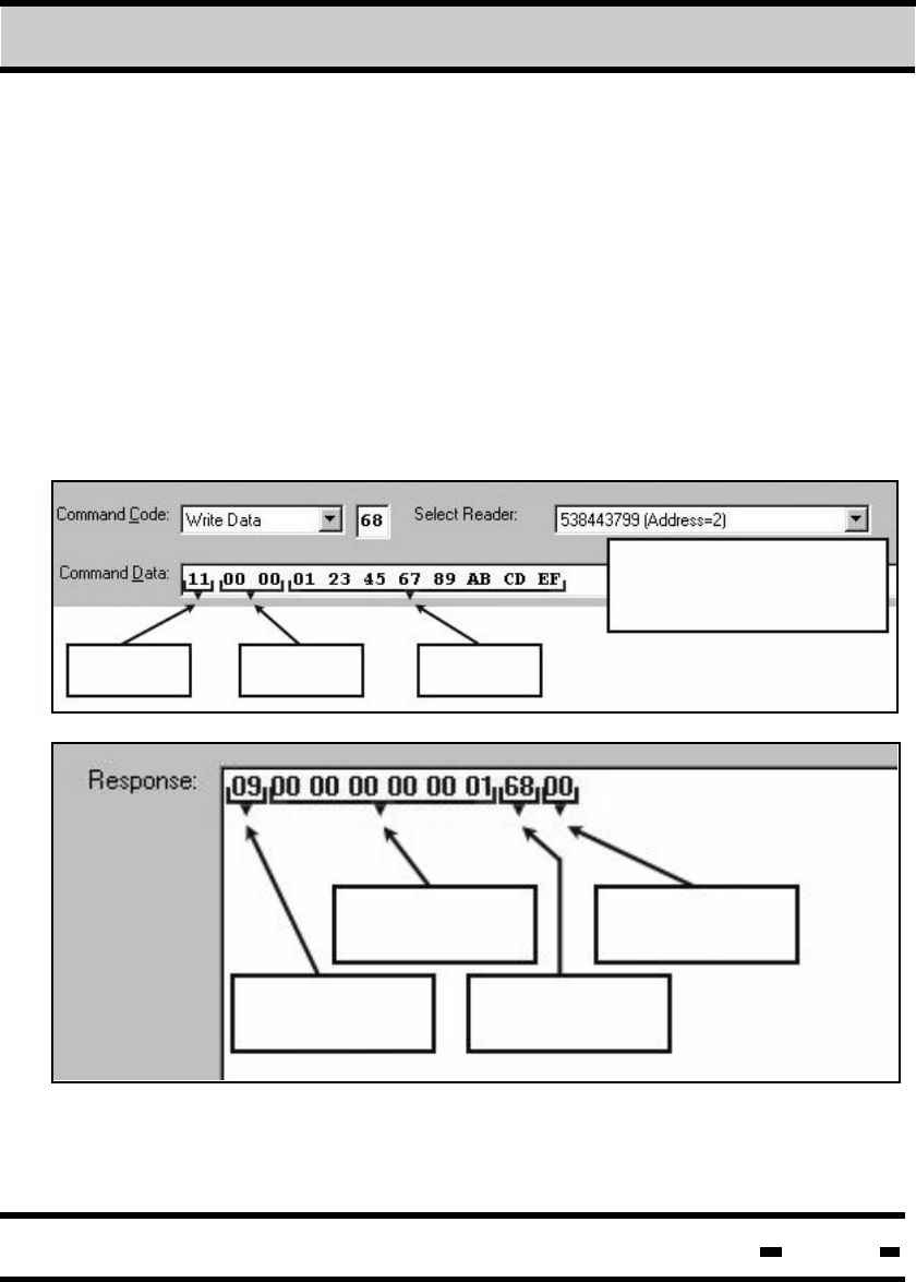
7.8.7.8. Write Data
The WRITE DATA command allows the User to write text in the entire
data area. This command can only work with one seal at a time.
There are two separate storage areas in each seal, ranging from
address 00 to address 53. The first area, from address 00 to 53, is
used to store data used by the DataTerminal. The data-range can
also be used by the HF system (reading and writing). Data stored
in address 54 to 2K is defined as a free high frequency area.
Maximum block size for a single session is 67 bytes.
In the event of a FAIL status response, the message type response
is "E8".
P#PK Base
Address
Data
Block
Read Data command
can only work with one
seal ID
Number
of bytes Msgt
Seal ID Short
Status
Hi-G-Tek Ltd. Microelectronics & Asset Tracking Technology 199
7Evaluation Software
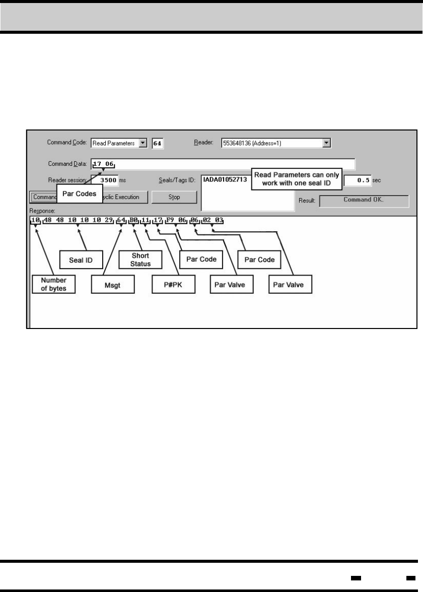
7.8.7.9. Read Parameter
The READ PARAMETER command enables the User to read
parameters from a single seal (see table 5.4).
Hi-G-Tek Ltd. Microelectronics & Asset Tracking Technology 200
7Evaluation Software
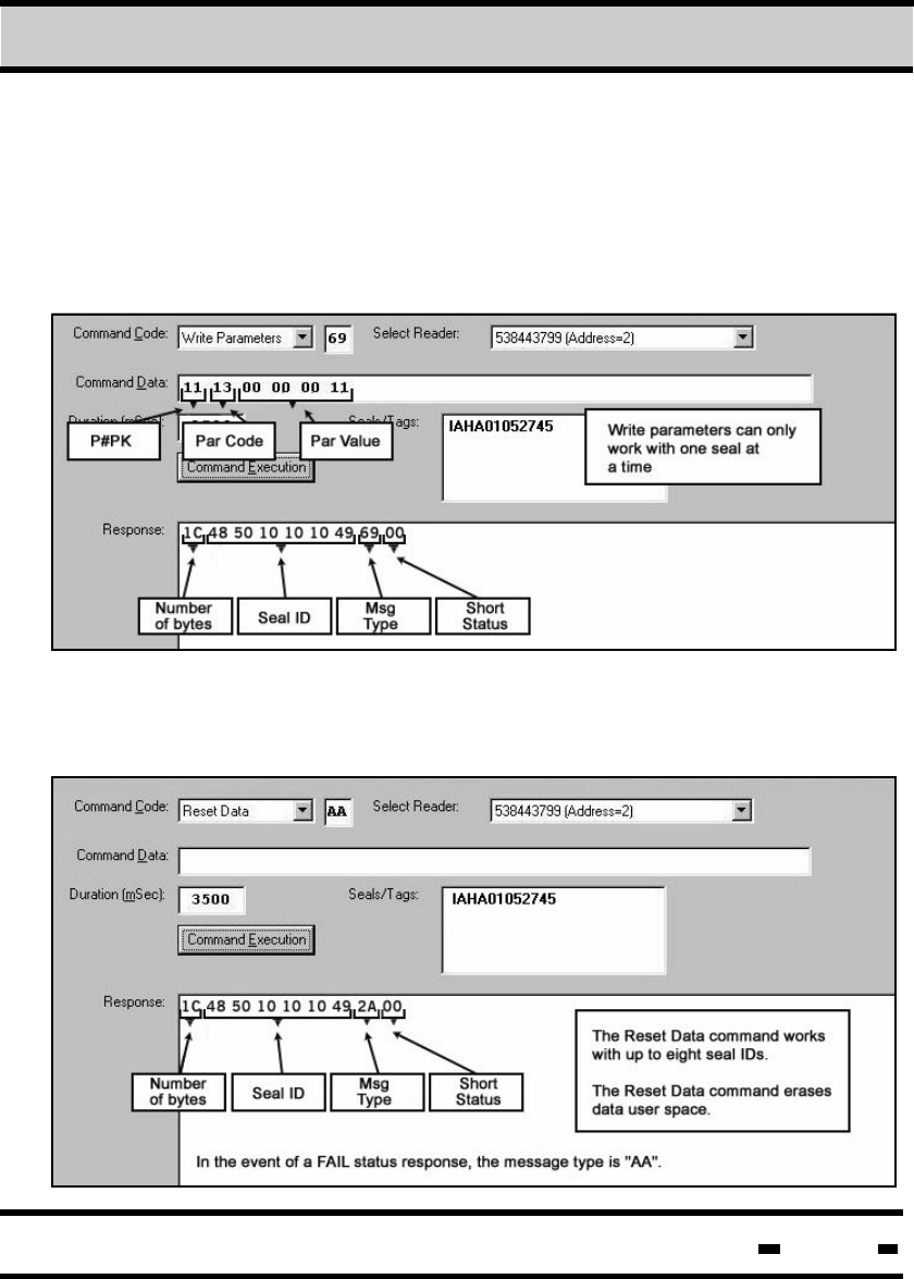
7.8.7.10. Write Parameter
The WRITE PARAMETER command enables the User to
update some of the seal parameters (see table 5.4).
The screen below illustrates an update of the ADI parameter. In the
event of a FAIL status response, the message type response is "E9".
The RESET DATA command allows the User to reset all USER DATA
from address 00 to address 2K.
7.8.7.11. Reset Data
Hi-G-Tek Ltd. Microelectronics & Asset Tracking Technology 201
7Evaluation Software
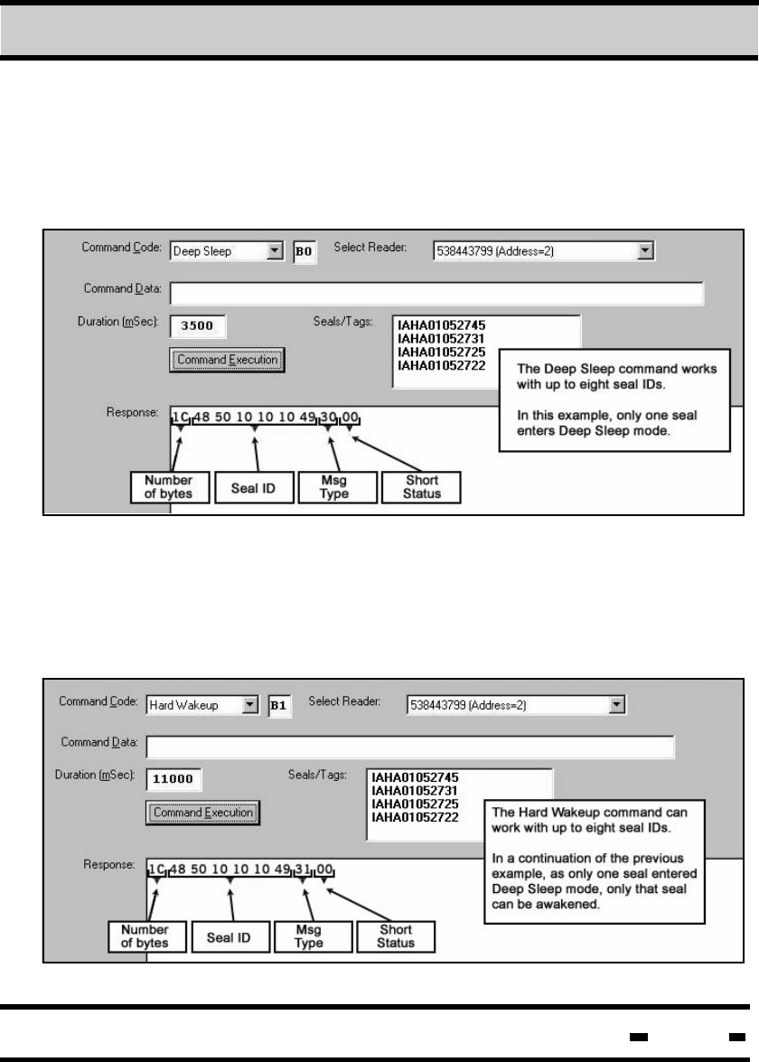
7.8.7.12. Deep Sleep
This command sends the seal into DEEP SLEEP mode. Prior
to initialization of the command, seal IDs must be defined. This
command can work with up to eight seals.
7.8.7.13. Hard Wakeup
The purpose of this command is to bring seals in DEEP SLEEP
mode back to regular operating mode. Only seals that are on the
seal ID list and are in DEEP SLEEP mode will be affected. This
command can work with up to eight seals at at time.
Hi-G-Tek Ltd. Microelectronics & Asset Tracking Technology 202
7Evaluation Software
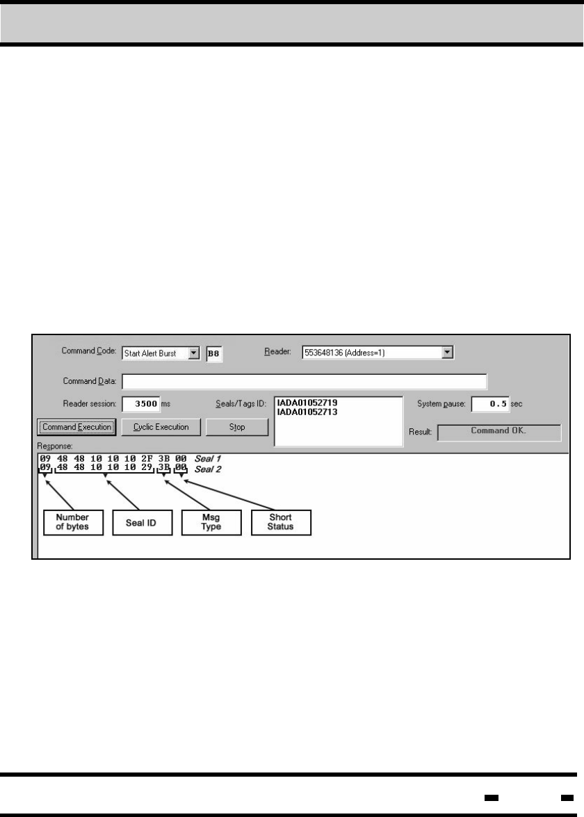
7.8.7.14. Start Alert Burst
The START ALERT BURST command transforms the seal from its
current operating mode to a burst mode of operation. In Alert
Burst operating mode, whenever a seal is opened a transmission
detailing the opened seal ID is automatically sent.
The START ALERT BURST command can work with up to eight
seals. The number of transmissions and the pause between
each transmission is predetermined (see table 5.4). The ACK
command, detailed in section 7.8.7.18, can be used to stop a
burst transmission.
Hi-G-Tek Ltd. Microelectronics & Asset Tracking Technology 203
7Evaluation Software
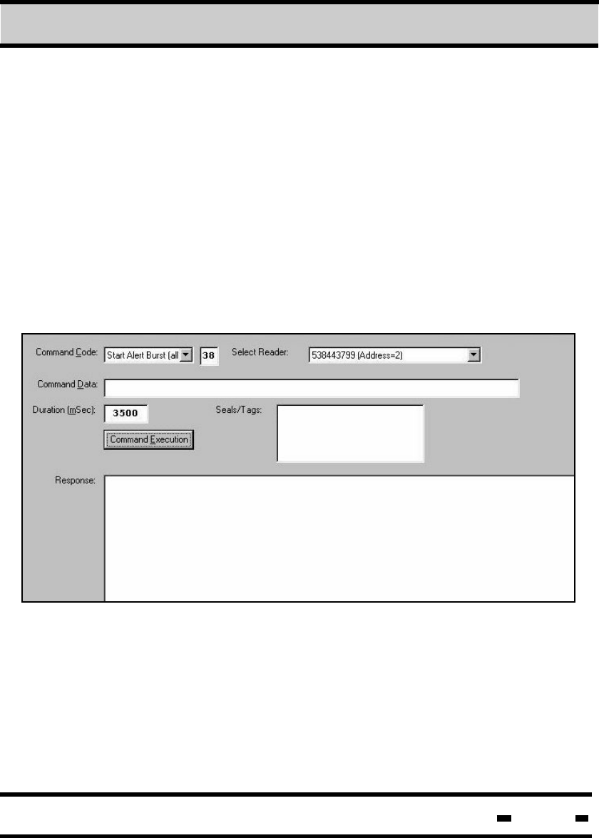
7.8.7.15. Start Alert Burst (all)
Similar to the START ALERT BURST command, the START
transforms the seal from its current
operating mode to a burst mode of operation. The difference
between the two is that in the case of START ALERT BURST
(ALL), all seals in the area will be transferred to this mode
of operation.
ALERT BURST (ALL)
No response is received in the RESPONSE window when the
the START ALERT BURST (ALL) command operates in
Broadcast mode.
Hi-G-Tek Ltd. Microelectronics & Asset Tracking Technology 204
7Evaluation Software
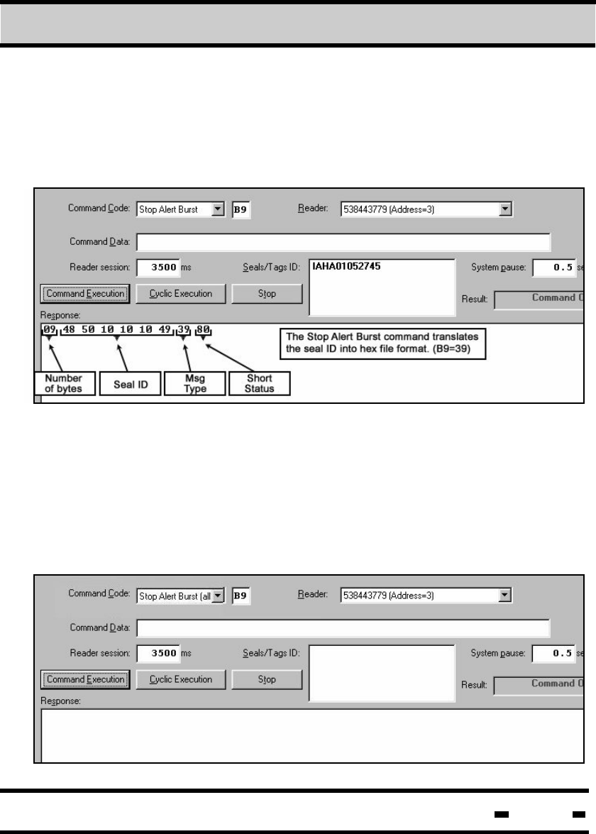
7.8.7.16. Stop Alert Burst
The STOP ALERT BURST command stops the seal from
working in Alert Burst mode and returns it to the regular mode
of operation.
The STOP ALERT BURST (ALL) command differs from the
STOP ALERT BURST command only in that it applies to all the
seals located in the Reader's vicinity. When the command is
transmitted in Broadcast mode, no reply is received in the
Response window.
7.8.7.17. Stop Alert Burst (all)
Hi-G-Tek Ltd. Microelectronics & Asset Tracking Technology 205
7Evaluation Software
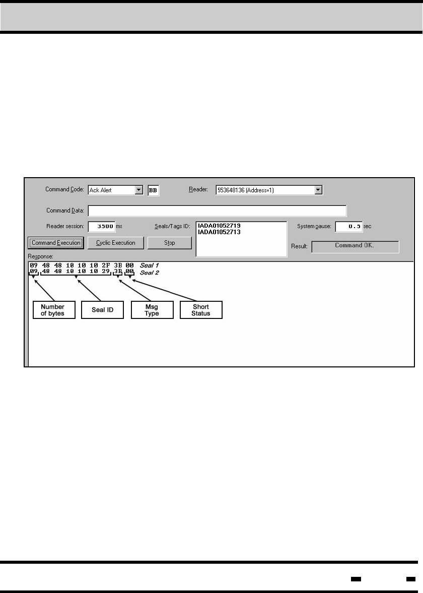
7.8.7.18. Ack Alert
The ACK ALERT command confirms to the seal that its message
has been received. After receiving an ACK ALERT command the
seal stops transmitting until a new TAMP EVENT is detected.
The ACK ALERT command can work with up to eight seals at
a time.
Hi-G-Tek Ltd. Microelectronics & Asset Tracking Technology 206
7Evaluation Software
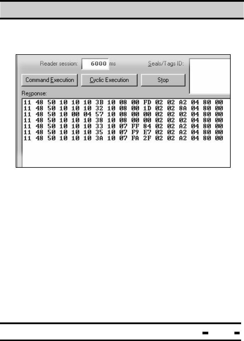
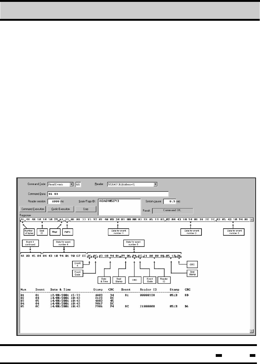
7.8.7.19. Read Events
The READ EVENTS command is used to read all events stored
in the EVENTS MEMORY.
As is illustrated in the sample screen below, the Command Data
field contains two numbers. The first defines the first event to be
read, the second number defines the total number of events to
be read.
The response is recorded in both hex and text formats. (See
table 5.8. for a list of appropriate events.)
The READ EVENTS command is compatible with two event
types: short events (8 bytes) and long events (16 bytes). In the
sample screen illustration below, events 1 and 5 are long events.
All the rest are short events.