User Manual
Hi-G-Tek
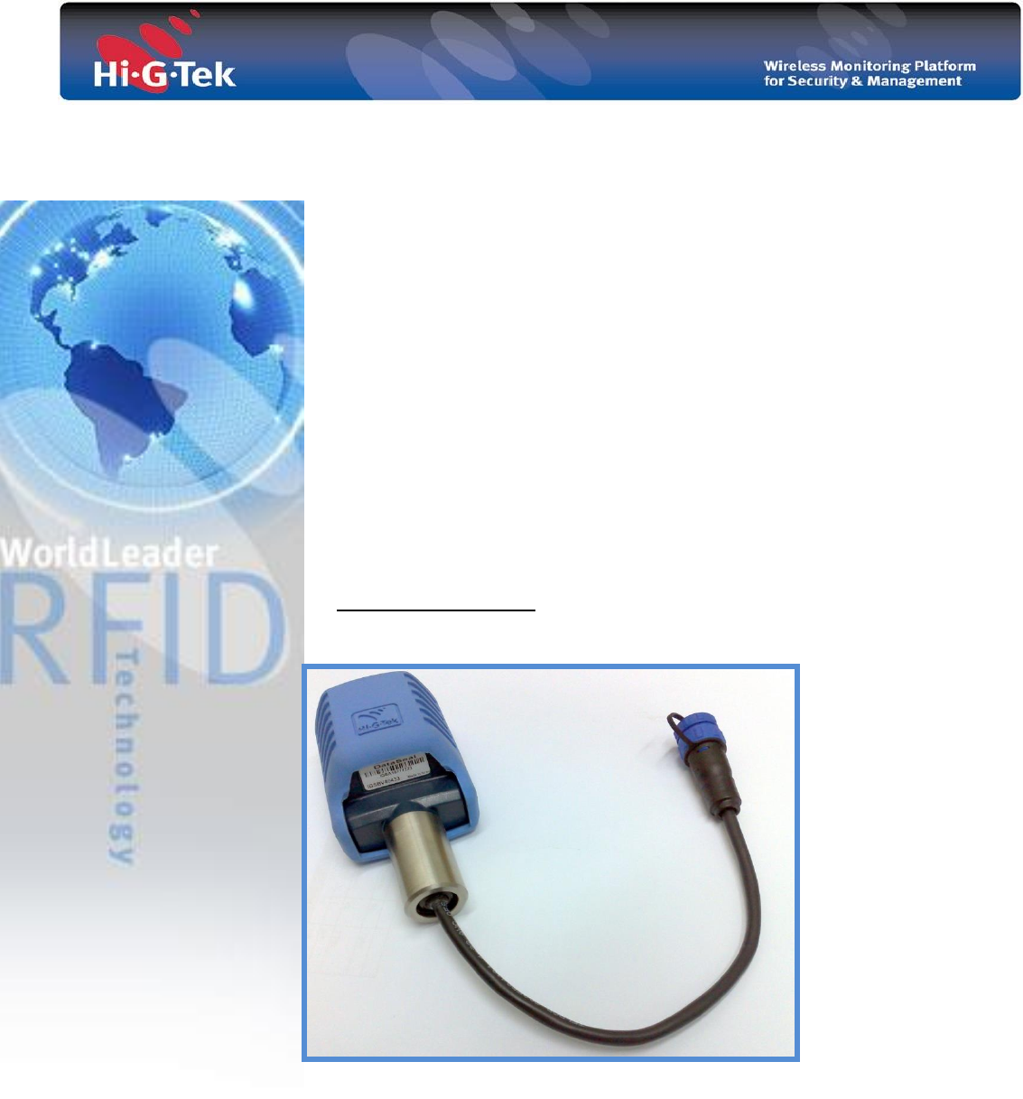
SPDS WIRELESS
ADAPTOR
User Manual
UM4801
Date: 26-Nov-13
Rev: 1.5
SPDS wireless adaptor- User Manual Page 2
1. Introduction
The following instructions describe and illustrate the principle steps involved in installation of
RFID tags operating as SPDS bottom valve wireless adaptor and SPDS vapor pressure valve
wireless adaptor.
The SPDS tag is portable, reusable electronic device designed to monitors the access point
through sensors and generate status information and alarms corresponding to various
programmed conditions. The wireless adaptor tag uses RFID (Radio Frequency Identification)
wireless technology- and includes a transmitter/ receiver unit, read/write capability, real-time
clock, memory sensing circuitry for sealing verification.
2. Product Models
This manual described the use of the products listed in the following table.
Due to differences in regulations regarding the use of RF spectrum, a product should be used
according to the following table:
Model Number
Used in
IG-SPV-40-433
Europe or where the EU directives apply.
IG-SBV-40-433
IG-SBV-40-916
Where the FCC regulation apply.
Forbidden for use in Europe.
IG-SBV-40-916
3. Safety Precautions
NOTE: The SPDS wireless adaptor electronic tag is powered by internal,
irreplaceable 3.6V cell; do not drill into or attempt to open any part of the tag
housing.
USE HIGTEK APPROVED SERVICE
Only approved service personnel must work on this product.
HAZARDOUS ENVIRONMENT
The Use of wireless adaptor tag is subject to the product safety classification given in
section 6 : “ATEX product marking”, in this user guide. For all other safety aspects,
Please refer to the enclosed EC- type examination certificate (page 8)
ACCESSORIES
Use only approved accessories. Do not connect incompatible devices.
When connecting to any other device, please consult with Hi-G-Tek Engineering
Department prior to installation.

SPDS wireless adaptor- User Manual Page 3
The device must not be used within non-conductive flowing media.
To the externals (Sensor-1, Sensor-2, Sensor-3 and Common) only passive
components, according to the user manual of the manufacturer, must be connected.
Switches and resistors must meet the simple apparatus requirements according to EN
60079-11. Resistors must meet the current-limiting resistors requirements according
to EN60079-11. The assembly of the connected components must comply with the
clearances and creepage distances requirements according to EN60079-11.
The FCC Wants You to Know
“This device complies with Part 15 of the FCC Rules. Operation is subject to the following
two conditions:
(1) This device may not cause harmful interference and
(2) This device must accept any interference received, including interference that may
cause undesired operation."
This equipment has been tested and found to comply with the limits for a Class B digital
device, pursuant to Part 15 of the FCC rules. These limits are designed to provide
reasonable protection against harmful interference in a residential installation. This
equipment generates, uses and can radiate radio frequency energy and, if not installed and
used in accordance with the instructions, may cause harmful interference to radio
communications. However, there is no guarantee that interference will not occur in a
particular installation.
If this equipment does cause harmful interference to radio or television reception, which
can be determined by turning the equipment off and on, the user is encouraged to try to
correct the interference by one or more of the
following measures:
a) Reorient or relocate the receiving antenna.
b) Increase the separation between the equipment and receiver.
c) Connect the equipment to an outlet on a circuit different from that to which the
receiver is connected.
d) Consult the dealer or an experienced radio/TV technician.
FCC Warning
Modifications not expressly approved by the manufacturer could void the user
authority to operate the equipment under FCC Rules.
Instructions concerning human exposure to radio frequency electromagnetic
fields:
A distance of at least 20cm. between the equipment and all persons should be maintained
during the operation of the equipment.
SPDS wireless adaptor- User Manual Page 4
4. SPDS bottom valve wireless adaptor
Product Part No. IGSBV40xxx
4.1. General
Adaptor shape is similar to the Data-Seal enclosure with the required
modifications for cable connection. RF channels specifications are identical
to the Data-Seal.
4.2. I/O’s
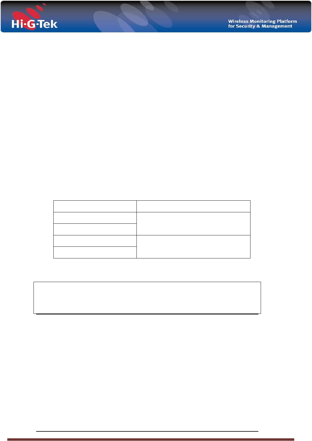
The adaptor has 3 inputs and internal reed switch.
The internal reed switch is used to sense removing of the enclosure from
installation fixture. A magnet should be installed in the fixture. See figure 1 and 2
for reed switch location. NCND D4X5mm magnet is recommended. Locate a
magnet in one of reed switch ends. Each one of the three inputs can be
configured to work in digital mode or analog mode. Digital mode gives the basic
ON/OFF functionality without tamper proof of the cable. In analog mode, the
sensor ON/OFF states are sensed and cable short or disconnect are sensed as
well.
4.3. Setting Digital /Analog mode
To work in digital mode simply connect the sensing switch to the cable. To work in analog
mode connect the sensor according to Figure 3 below.
21.7
73
6.5
73
6.5
24.7
Figure 3: Connecting the sensor:
: 2Figure
Internal reed sw. location with rubber Jacket
1.6Meg
5%
Sensing
reed switch
5.1Meg
5%
: 1Figure
Internal reed sw. location without rubber Jacket
SENSOR-3
COMMON
SENSOR-2
SENSOR-1
FRONT VIEW
1
2
3
4
SPDS wireless adaptor- User Manual Page 5
4.4. Input specifications:
Input type: Dry contact.
Polarity: Internally pulled HIGH, Activated when pulled LOW.
Protections: ESD.
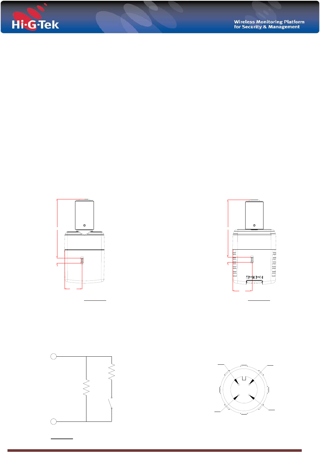
4
3
2
1
FRONT VIEW
PIN #
4
3
2
1
BLACK
RED
GREEN
WHITE
BLACK
RED
BLACK
BLACK
GREEN
WHITE SHIELD
Figure 4: Extension cord (p/n IGSBVEC01): Pinout & wiring diagram:

SPDS wireless adaptor- User Manual Page 6
5. SPDS vapor pressure valve wireless adaptor
Product Part No. IGSPV40xxx
5.1. General
Adaptor shape is similar to the DataSeal enclosure with the required
modifications for cable connection. RF channels specifications are identical
to the DataSeal.
The adaptor controls the relay of the pneumatic system and reads the
status of the air pressure.
5.2. I/O’s
The adaptor has one input, one output and internal reed switch. The
internal reed switch is used to sense removing of the enclosure from
installation fixture. A magnet should be installed in the fixture. See figure 1
and 2 for reed switch location. NCND D4X5mm magnet is recommended.
Locate a magnet in one of reed switch ends.
The input can be configured to work in digital mode or analog mode. Digital
mode gives the basic ON/OFF functionality without tamper proof of the
cable. In analog mode, the sensor ON/OFF states are sensed and cable
short or disconnect are sensed as well.
To work in digital mode simply connect the sensing switch to the cable.
To work in analog mode connect the sensor according to Figure 3.
5.3. Output specifications:
The output is open drain type with specifications as follows:
Output type: Open-drain.
Maximum load: 24VDC relay with 230Ω minimum resistance.
Maximum open circuit voltage: 32V.
Functionality: ON- Pulse with configurable width.
Maximum ON pulse width: 10Sec.
Protection diode should be connected externally on relay terminals.
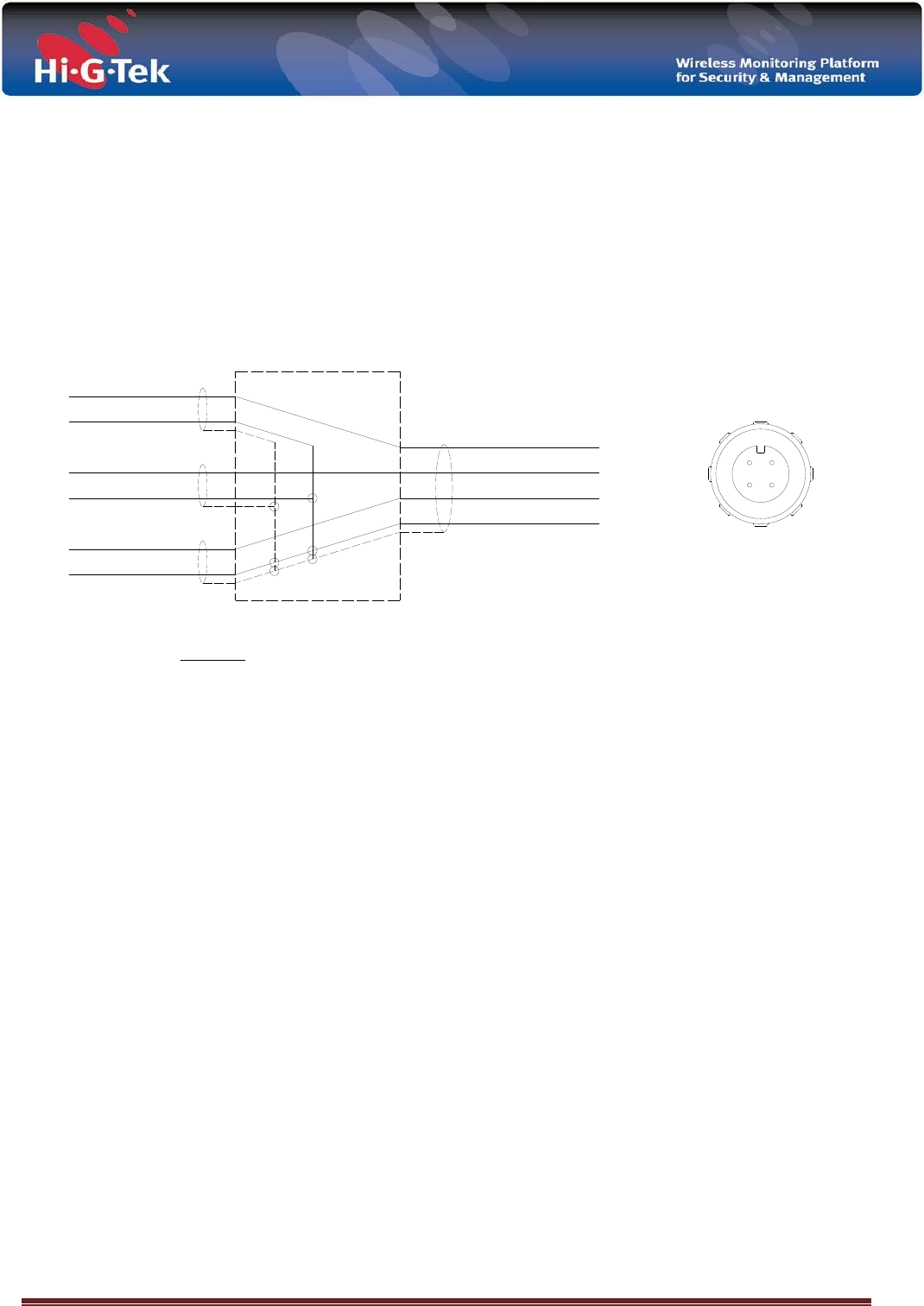
Extension cord (IGSPVEC01) pinout diagram:
PIN #
4
3
2
1
RED
GREEN
WHITE
BLACK FRONT VIEW
1
23
4
SPDS wireless adaptor- User Manual Page 7
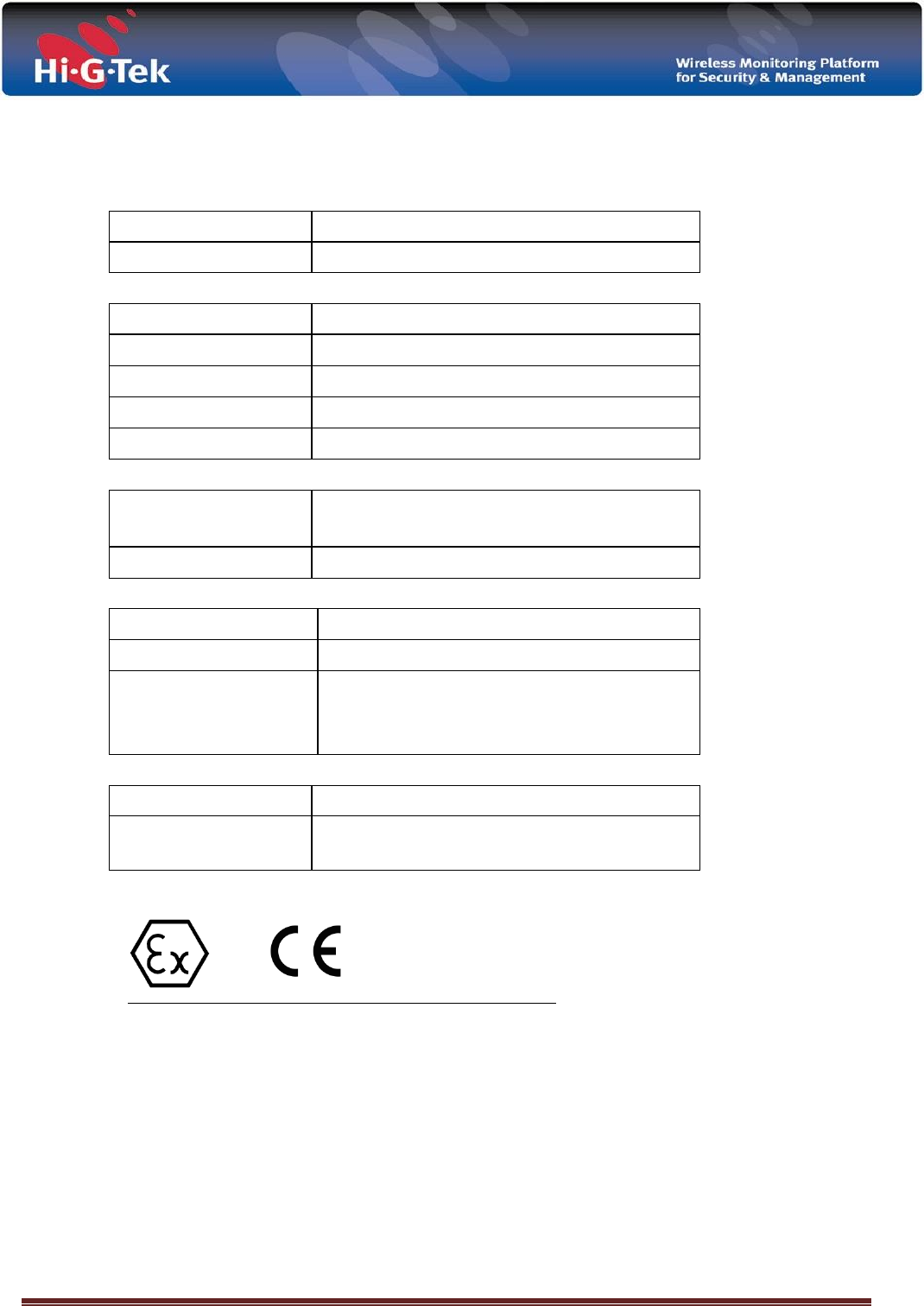
6. Technical specifications.
Power requirements
Power Source
3.6V internal Lithium battery
Life Expectancy
4 years at 50 readings per day
Communication channels:
Low frequency
125 kHz
Low-frequency range
Up to 40cm
High frequency
Model:IGSxV40433 433.92MHz
Model:IGSxV40916 916.50MHz
High-frequency range
Up to 100m (in open space)
Antenna Characteristics
Beam Divergence
Omni-directional on non-metal wall
Hemispherical on metal wall
Polarization
Vertical
Physical Characteristics:
Dimensions
63 x 49 x 37mm (without pin and lock)
Weight
150gr
Environmental Conditions
Operating Temperature : -40°C to +70°C
Storage Temperature : -40°C to +80°C
Protection Classification : IP65
I/Os
Input type
Dry contact
Polarity
Internally pulled HIGH, Activated when pulled
LOW. Protections: ESD.

SPDS wireless adaptor- User Manual Page 8
7. ATEX Marking
II – Equipment Group II: Surface (no-mining) equipment.
2 - Equipment Category 1: Very high degree of protection for use in Zone 0.
G – Atmosphere Group: Gases, Vapors, Mists
Ex- Explosion proof equipment: The Equipment that has been certified
for use in a Potentially Explosive Atmosphere
ia - A protection technique based upon the restriction of electrical energy
within the apparatus and in the interconnecting wiring, exposed to a
explosive atmosphere, to a level below that which can cause ignition by
either sparking or heating effects. “ia” - Indicates that the electric circuit is
not able to cause an ignition when there are two failures (“ib” is for a single
failure situation).
IIB - Gas group B: Ethylene - typical gas in petrochemical environment.
T4- Temperature classification (max.135ºC)
Ex ia IIB T4
0539
9
II 1 G

SPDS wireless adaptor- User Manual Page 9

SPDS wireless adaptor- User Manual Page 10

SPDS wireless adaptor- User Manual Page 11