Hi Target Surveying Instrument HTSMINI total station User Manual Preface
Hi-Target Surveying Instrument Co., Ltd total station Preface
UserManual.wiki
>
Hi Target Surveying Instrument
>
HTSMINI User Manual
User Manual
Navigation menu
Upload a User Manual
Namespaces
Wiki Guide
HTML
PDF
Info
Views
User Manual
Discussion / Help
Navigation
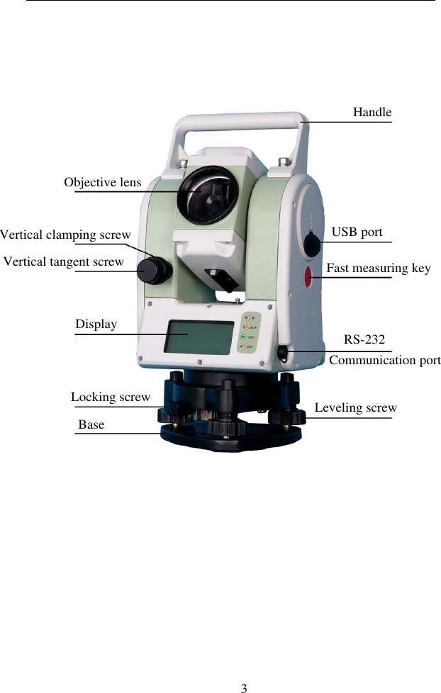
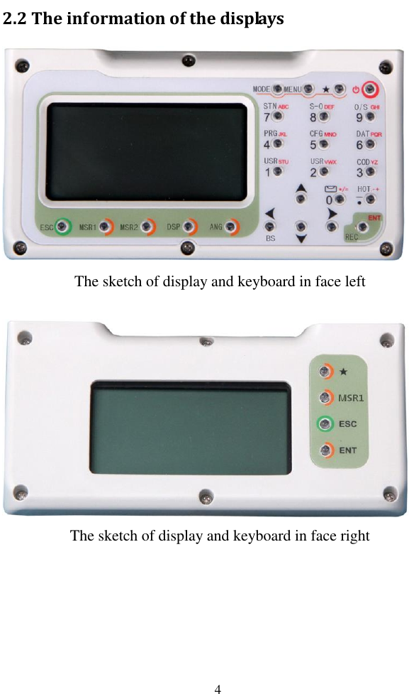
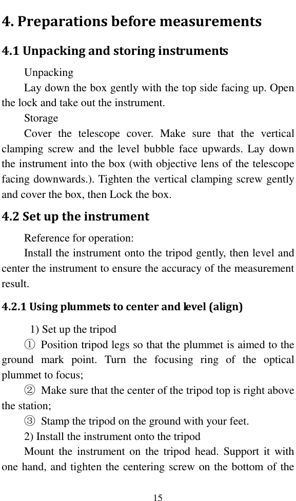
![7 Content 1. Use of instrument.............................................................. 1 2. Names and functions of the components ................. 2 2.1 Names of the components ........................................... 2 2.2 The information of the displays ................................ 4 3. Initial setup ......................................................................... 8 3.1 On & Off .............................................................................. 8 3.2 Set up the tilt correction of horizontal and vertical angles .................................................................................... 8 3.3 Settings of star [★] key. ............................................... 9 3.4 Setting for measurement parameters ..................10 3.4 Settings of hot key[▪]. ..................................................11 3.4.1 Input of target height .....................................11 3.4.2 Settings of temperature and pressure ....12 3.4.3 Inputs of Note. ..................................................13 3.5 Select data files ................................................................14 4. Preparations before measurements ........................ 15 4.1 Unpacking and storing instruments......................15 4.2 Set up the instrument .................................................15 4.2.1 Using plummets to center and level (align) .....................................................................................................15 4.2.2 Using centering device to center ...............17 4.3 Loading and unloading of battery ..........................18 4.4 Reflecting Prism. ...........................................................19 4.5 Loading and unloading of the pedestal .................19 4.6 Adjusting eyepiece lens of the telescope and aiming the target. ...........................................................................19 4.7 Entering letters and numbers ..................................20 4.8 Retrieve points ...............................................................23 4.9 Measured point .............................................................25](https://usermanual.wiki/Hi-Target-Surveying-Instrument/HTSMINI/User-Guide-3281758-Page-8.png)
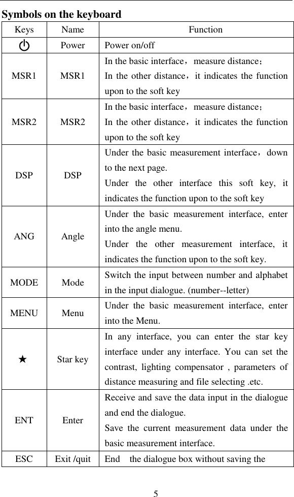
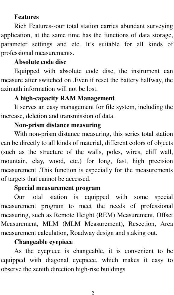
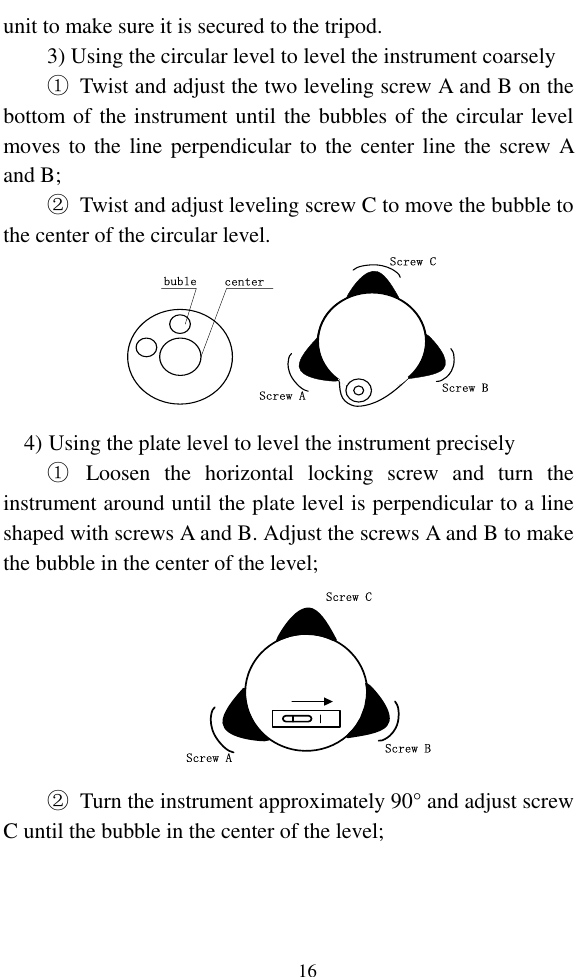
![6 input,and return to the previous step ◄► Left /right change the option in the select box Data list page ▲▼ Up /down Move the Cursor up and down in order. Turn the page under the basic measurement. 0~9 Number Input number and characters and select one of menu. “0”: Enter the electronic bubble interface under the basic measurement. · Symbols Enter symbols, decimals and signs; Enter the interface for input height. The side key Fast measurement key This function is equal with it of the key [MSR1]. It works just in the measurement interface, and does not work in the others. Symbols on the display Symbols Indication Vz Zenith Mode Vo The mode that the vertical is displayed as zero when the telescope is level in normal Vh Vertical angle Mode (it is 0°00′00″when the telescope is level. The angle of elevation is positive and the angle of depression is negative.) V% Slope Mode HR Horizontal angle (right angle). dHR means the angle difference of setting out. HL Horizontal angle (anticlockwise increment) HD Horizontal distance. dHD is to stake out horizontal distance difference. VD Elevation difference. dVD is to stake out difference between elevation differences.](https://usermanual.wiki/Hi-Target-Surveying-Instrument/HTSMINI/User-Guide-3281758-Page-18.png)
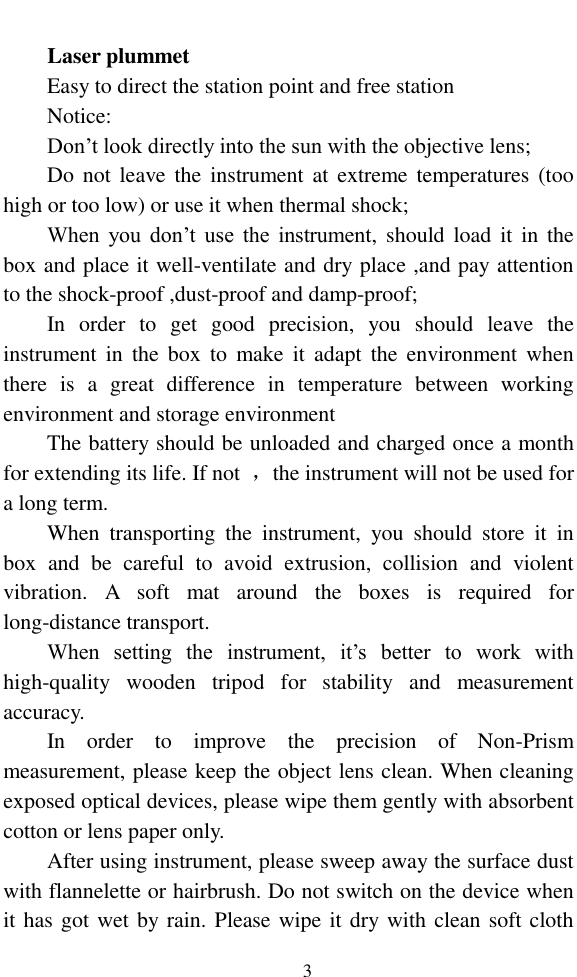
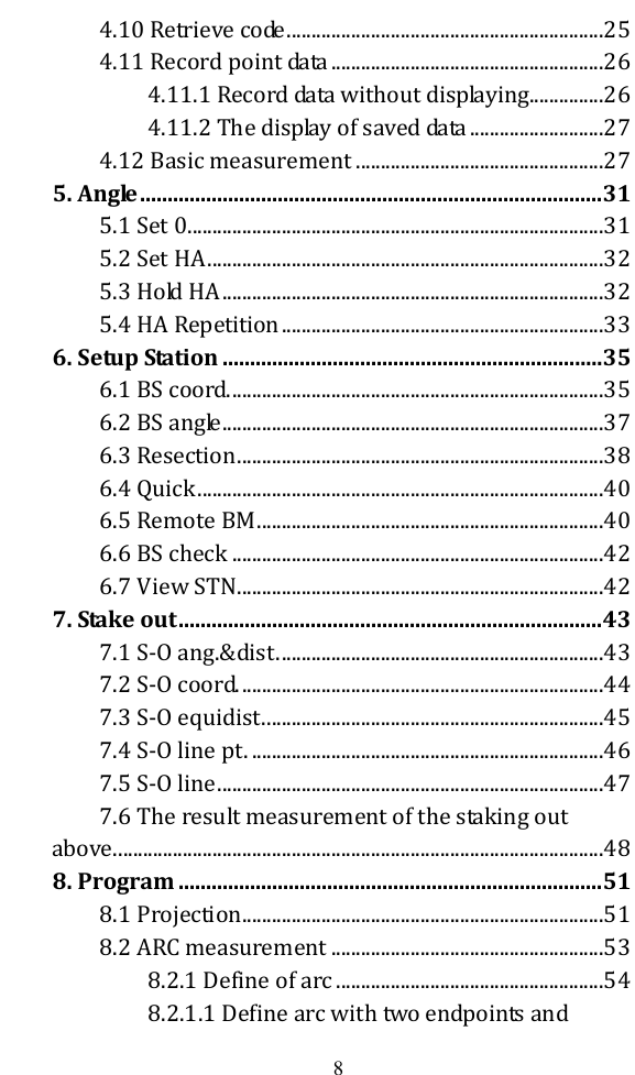
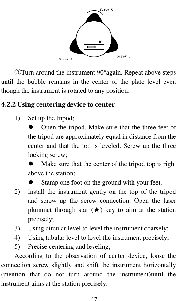
![8 3. Initial setup 3.1 On & Off Press and hold the key ‘On/Off’ (the buzzer remains buzzer) until the screen displays pictures. The instrument is now switched on. After self-checking, the instrument enters Angle Mode automatically (see details in 5. Angle Mode for details) Pressing power key will leads to a dialogue box. Press [ENT] to turn off the instrument. 3.2 Set up the tilt correction of horizontal and vertical angles When the tilt (inclination) sensor is on, the instrument will display the automatic correction value for the vertical angle caused by not strictly level. In order to ensure the accuracy of the angle measurement, try to use tilt sensor whose display can be used to level the instrument better. If displaying ‘Tilt over!’ in the ‘Vz’ column, it indicates that the instrument beyond the range of the automatic compensation, and it needs to be leveled by adjusting foot screw. Operations :under the basic measurement interface, press the key [0],then enter the electric bubble interface as follow: BubbleDIGIT↔D AS AOFFONON ↔ 1)The horizontal arrow “↔” will displays “OF” by](https://usermanual.wiki/Hi-Target-Surveying-Instrument/HTSMINI/User-Guide-3281758-Page-20.png)
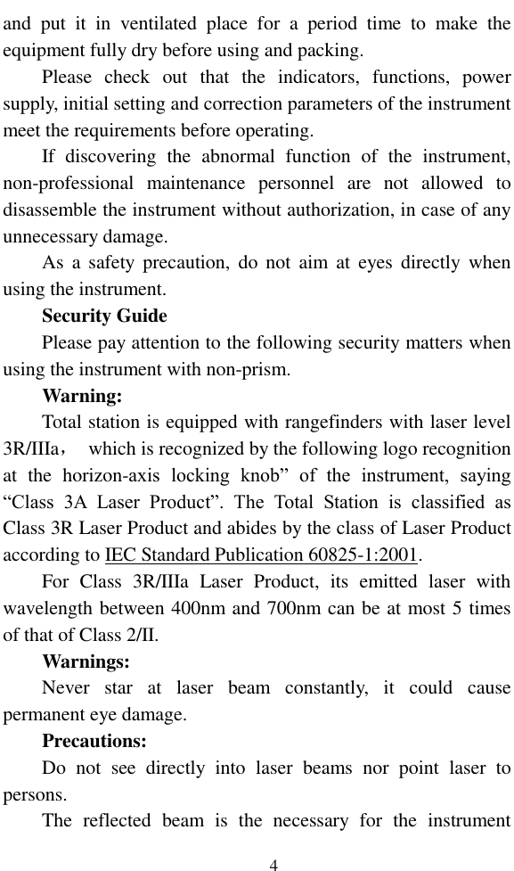
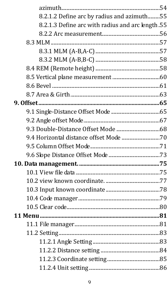
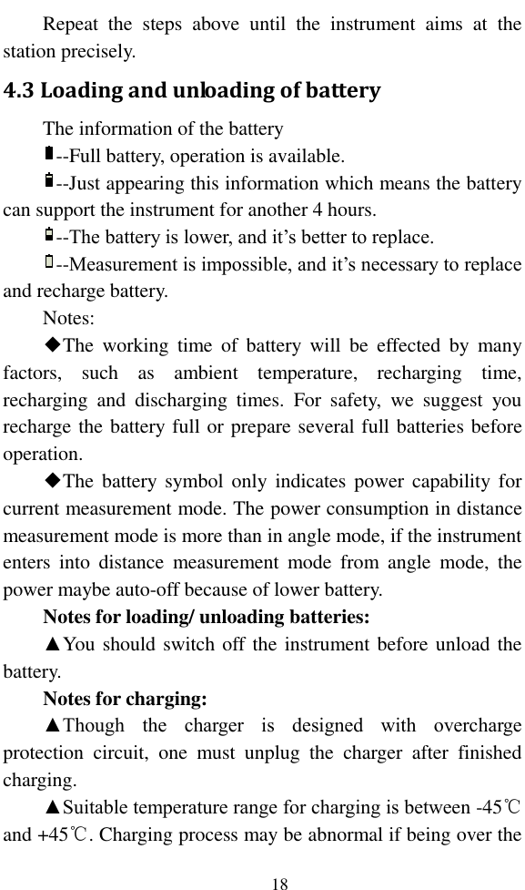
![9 press the key [S A], and the data of “Tilt Y” will display zero by press [DIGIT] when the instrument is equipped with single-axis compensator; 2)Press [OFF] to close the compensator; 3)Press [S A] to open the compensator of the vertical direction and close the compensator of the horizontal direction; 4)Press [D A] to open the compensator of the two directions.(For the instrument equipped with dual-axis compensator); 5)Press [DIGIT] to display the value of compensator, which is real-time refresh, and the button of [DIGIT] is changed [GRA.] .Press the [GRA.] to return to the graphical display interface; 6)Press [ENT] or [ESC] to come back to basic interface. 3.3 Settings of star [★] key. Except for the menu interface, you can press [★] to enter the following interface. Shot cutBeep:-Contrast:+LASERLIGHTOF ►4 ▲ ▼ The settings of star[★] key as below: 1) Switch key for buzzer each time you press the [►] switch on or off the buzzer circularly; 2) Contrast adjusting: adjust the contrast of display by](https://usermanual.wiki/Hi-Target-Surveying-Instrument/HTSMINI/User-Guide-3281758-Page-21.png)
![10 pressing the key [▲] or [▼]; 3) Backlight: each time you press the key [Light], the backlight of display can switch between the brightness (for three levels) and off circularly; 4)Laser: Each time pressing the key [LASER] can switch on or off the laser; 5) laser plummet: you can increase the laser plummet brightness until the brightest by press [+],and you can also press [﹣] to decrease the laser plummet brightness until off it. 3.4 Setting for measurement parameters You can press the [5] to set the measurement parameters under all measurement interfaces. -------Config------1.[MSR1] Config2.[MSR2] ConfigReflect:PSM:Mode:Meas Setting-MSR1Count:Record:03 ENT▲ ▲ Track ▲ ▲ Prism ▲ ▲ This series total station is equipped two measurement keys,[MSR1] and [MSR2] and each of them is equipped with measurement parameters. Whichever you select, you can equip the measurement parameters under the menu of “Config” interface. Here,as an example to the key [MSR1] 1) You can press the key [ENT] or [▼] to move the focus down and also press [▲] to move the focus up when complete to set one parameter; 2) You can change the options by pressing the key [◄] or [►]; 3) After the last setting completed, you can press [ENT] to save the settings, and return to the last interface; 4) Reflect: you can select “prism”, “NP”(for Non prism](https://usermanual.wiki/Hi-Target-Surveying-Instrument/HTSMINI/User-Guide-3281758-Page-22.png)
![11 instrument) , “RB’(reflector board); 5) PSM: Prism constant .Generally as “0” or “30”,if the prism is special, you need to input itself constant value; 6) Mode: Distance measurement mode .You have four options to select, which are “Single”, “Rept.”, “Avg.”(Set by “count”), “Track”(Fast but low accuracy) . The “Single” measurement and “Avg.” measurement can be ended automatically after a successful measuring. But if you want to end the “Track” and “Rept.” measurement, you must press the key [ESC]; 7) Count: Times of the “Rept.” measurement. The range is “1” to “9”; 8) Record: to set the mode of storing data under the basic measurement. You can choose “ENT” (press [ENT] to enter the “rec. data” interface.), “AUTO” (record the measured data automatically after a successful measurement), “NO”(won’t record the measured data , even though pressing [ENT]). 3.4 Settings of hot key[•] Under the basic measurement interface, you can press the hot key [▪] to enter the “Hotkey” interface. ----Hotkey----1.T.H3.Note2.Temp-Press 3.4.1 Input of target height If you want to change the current system default of target](https://usermanual.wiki/Hi-Target-Surveying-Instrument/HTSMINI/User-Guide-3281758-Page-23.png)
![12 height, you can apply this function. Under the “Hotkey” interface, press the key [1] to enter the “Input T.H” interface. Input T.HT.H:m 1) After you input the target height , press [ENT] to save the target height to the system parameters .when you enter another interface which displays the target height ,the value will be the system default until you change it; 2) The range of input is “-999.999” to “999.999” .if out of range, it will prompt you; 3) Press [ESC] to come back to the “Hotkey” interface with not saving the value of target height. 3.4.2 Settings of temperature and pressure When measuring distance, the measured value can be influenced by the atmosphere. In order to reduce the influence, an atmospheric correction parameter (which is calculated by current temperature and atmospheric pressure values) is needed. The standard atmospheric value of this series Total Station (i.e. the atmospheric conditions when the correction is zero) Atm: 1013 Pa Temp:20℃ The calculation of atmospheric correction PPM= 277.825- 0.29434P/(1+0.003661T) (ppm) In the formula: PPM: correction coefficient (unit: ppm)](https://usermanual.wiki/Hi-Target-Surveying-Instrument/HTSMINI/User-Guide-3281758-Page-24.png)
![13 P: atmospheric pressure (unit: hPa) T: temperature (unit:℃) Under the “Hotkey” interface, press [2] or press [ENT] when the focus is at “2.Tem-Press” to enter the “Input TP” interface. Input TP20 Temp: Press: 1013 PPM:℃hPa10 1) Temp: temperature value, only need integer part,the range is “-30℃” to “60℃”; 2) Press: Atmospheric pressure ,only need integer part, the range is “500hpa” to “1400hpa”; 3) PPM: the value will be changed when the temperature or pressure changed; 4) Press [ESC] back to the “Hotkey” interface without saving the changed value. 3.4.3 Inputs of Note. If you want to note simple information, this function can help you. Under the “Hotkey” interface, press [3] or press [ENT] when the focus is at “3.Note” to enter the “Input Note” interface. Input Note*[ENT] record1 1) You can input notes by pressing [Mode] to switch the](https://usermanual.wiki/Hi-Target-Surveying-Instrument/HTSMINI/User-Guide-3281758-Page-25.png)
![14 input mode. Maximum of 50 characters; 2) After inputting the notes, press [ENT] to record it and then a prompt box “NOTE rec. OK” appears and back to the “Hotkey ” interface; 3) The information of note is recorded to the current measurement file; 4) You can press [ESC] to return to the “Hotkey” interface under the “Input Note” interface. 3.5 Select data files The instrument needs large data and creates large data when it is operated. These data are storied in the system files as a file form. It’s a good habit that select measurement files what you need before working, otherwise, your measured data can’t be saved.(see reference in “11. File management”.)](https://usermanual.wiki/Hi-Target-Surveying-Instrument/HTSMINI/User-Guide-3281758-Page-26.png)
![20 proper distance (about 200mm) away from the sighting device; 3) Obtain a sharp image of the target on the reticule with the focusing screw. If optical parallax appears when angle of view changed, the focus or the diopter of the eyepiece may be unadjusted. For precision concerns, please adjust the eyepiece focus to eliminate the optical parallax carefully. 4.7 Entering letters and numbers This series total station has been equipped the key [Mode], which can be convenient to switch the input mode between letters and numbers. ● Input letters Example 1: Take inputting code for example, which needs to input “Co1” in the edit box 1) Press [Mode] to switch to the mode of inputting letters. There is a symbol displayed as “A” beside battery; Input codeCode:A 2) Press [1], then, “S” displays in the edit box; Input codeSCode:A 3) Wait 0.3 seconds, then press [1] again, “T”displays in the edit box; 4) Wait 0.3 seconds,then press [1] again, “U”displays in the edit box;](https://usermanual.wiki/Hi-Target-Surveying-Instrument/HTSMINI/User-Guide-3281758-Page-32.png)
![21 5) The interval of pressing the key [1] twice is not over 0.3 seconds .If over,another letter will be input. If press the key [1] constantly, it will be circular between “S” “T” “U” “1” “S”. The operation of the other number keys (“0~9”) is as same as it of the key [1]; 6) Press the key [5] constantly again, “CO” displays in the edit box; Input codeCOCode:A 7) Press [Mode] to switch to the mode of inputting numbers. There is a symbol displayed as “1” beside battery; 8) After press the key [1],the interface is as follows: Input codeCO1Code:A 9) Pressing [◄] can delete the character in the front of cursor; 10) Pressing [►] can move the cursor circularly. When it moved to the last, comes back to the first. ● Input numbers Example 2: Take Inputting target height for example, which needs to input “1.562” in the edit box. 1) Because the target height can’t be letter, the inputting mode will default to number “1”, and can’t be](https://usermanual.wiki/Hi-Target-Surveying-Instrument/HTSMINI/User-Guide-3281758-Page-33.png)
![22 switched to the letter mode “A”. The interface is as follows; Input T.HT.H:m1 2) The order of the keys:[1]→[·]→[6]→[5]→[2]; 3) The result is shown below: Input T.H1.652T.H:m1 4) After completing the input, press [ENT] to record the input and end the edit box; ● Input angles Example 3: Enter the “Input Angle->Set A” interface of angle menu, which needs to input “123°45′56” in the edit box of “HR”. Input Angle->Set AHR:1*[ENT]to set A 1) The order of the keys:[1]→[·]→[6]→[5]→[2]; 2) The result is as shown below:](https://usermanual.wiki/Hi-Target-Surveying-Instrument/HTSMINI/User-Guide-3281758-Page-34.png)
![23 Input Angle->Set A123.4556HR:1 *[ENT]to set A 3) After completing the input, press [ENT] to confirm the input or press [ESC] to cancel it. If it is over “360°”, a prompt box will appear. 4.8 Retrieve points In the software functions of this series total station, we need to retrieve or input the coordinate data of points in many places, but the method is same. Take the “Project->base” for example. Pt.1:Project->baseMEAS KNOWNPt.2:ENTA ● Retrieve the point of data files 1) Before retrieve the point, you must select a data file. Specific operations see chapter “11.File manager”; 2) If you remember all points name, you can input the name directly, then press [ENT],and the coordinate data displayed as follows; Pt.N:Code:Coord. dataN:E:Z:146.325 m265.364 m1.256 m56road 3) If just remember a part of point name, you can find the point by “*”.For example, input “5*”, you can find](https://usermanual.wiki/Hi-Target-Surveying-Instrument/HTSMINI/User-Guide-3281758-Page-35.png)
![24 some points whose name contains “5”, which are displayed in the list(as shown below).Then, move the cursor to the wanted point and press [ENT],and it will display the coordinate of the wanted point and back to the previous interface; Pt.1:Project->baseMEAS KNOWNPt.2:ENTAPt. list1235612357▲ 4) If the point input isn’t exit, you can enter the input interface (as shown below).after the input, it save the input data to the retrieved file, and then come back; Input coord.N:E:Z:mmmPt.N:Code: code31 5) If you don’t input point name, then you will enter the coordinate input interface (as shown below), and it will not save the data, and come back directly; ●Retrieve known points The operation of retrieving known point is same as it of retrieve data files, but the differences are as below; 1) The data of coordinate point is retrieved in the known files 2) Input the point name and press the key [ENT]; 3) If the point doesn’t exit, it will tip you that “No data match”, and it doesn’t support direct input. 4) The point name can’t be null.](https://usermanual.wiki/Hi-Target-Surveying-Instrument/HTSMINI/User-Guide-3281758-Page-36.png)
![25 4.9 Measured point In the software functions of this series total station, we need to retrieve or input the coordinates data of points in many places as well as obtain the coordinate data by field measurements. The method is as same as retrieving points. Take“Project->base” for example. Pt.1:Project->baseMEAS KNOWNPt.2:ENTA 1) Press the key [MEAS], then enter into the interface (as shown below; Meas. targetHR:Vz:SD:*[Hot] to set T.HMSR1 MSR2m45º23'53"89º52'36" 2) The angle displays real time, and press [MSR1] or [MSR2] to start measuring; 3) After a distance measurement is ended and successful (if repeat mode or track mode, you should press [ESC] to end.), enter the interface of saving data automatically. After saving successfully, it will come back to the point input interface, and refresh to display the saved point. 4.10 Retrieve code On the interface with inputting code, you can input code by retrieving. 1) Press [LIST] to enter the code list (as shown below), and press [◄] or [►] to move cursor;](https://usermanual.wiki/Hi-Target-Surveying-Instrument/HTSMINI/User-Guide-3281758-Page-37.png)
![26 Code manager 1/1SRH. ADDDEL. LASTcode1code2 2) If the code data are multipage,you can move the cursor to the last and move cursor again, then you can press [▼] to next page, or you can press [◄] or [►] to next page; 3) After select the code, press [ENT] to come back, and the code will be refreshed. 4.11 Record point data 4.11.1 Record data without displaying 1) Under the functions with saving data, press [REC.] to enter the interface of recording data ,which will displays the default “Pt .N”, “T.H”, “Code”, and the cursor is at the place where input code; 2) If want to change “Pt .N”, “T.H”,you can move cursor where you want to change by pressing [▲] and [▼]; 3) When moving the cursor to “Code”, you can press [LIST] to retrieve code; 4) When the cursor is at “Code”, you can press [ENT] to save data. After the save is successful, it will tip you; 5) If the saved data are coordinate and the target height is re-input, the value of Z-coordinate will be re-calculated.](https://usermanual.wiki/Hi-Target-Surveying-Instrument/HTSMINI/User-Guide-3281758-Page-38.png)
![27 4.11.2 The display of saved data HR:Vz:SD:DSP REC. LIST DSP REC.Z:N:E:[DSP][DSP]Pt.N:Code: 1codePt.N:Code:45º23'53"89º52'36"AA1code42.365 m146.325265.364 m1.256 m 1) Under the functions with saving data, press [REC.] and enter the interface of recording data ,which will displays the default “Pt.N”, “T.H”, “Code”, and the cursor is at the place where input name; 2) When the cursor is at “Code”, you can press [LIST] to retrieve code; 3) Pressing [DSP], the displayed data will be changed between angle -distance and coordinate; 4) When the cursor is at “Code”, you can press [ENT] to save data. After the save is successful, it will tip you. 4.12 Basic measurement You will enter the basic measurement after switch on the instrument. There are three interfaces about basic measurement.](https://usermanual.wiki/Hi-Target-Surveying-Instrument/HTSMINI/User-Guide-3281758-Page-39.png)
![28 HR:Vz:SD:Pt.N:T.H:Basic 1/3Pt .N:T.H:Basic 3/3Z:N:E:HD:VD:Pt .N:T.H:Basic 2/3[DSP]/[▼]SD:[DSP]/[▼][DSP]/[▼][▲][▲][▲]45º23'53"89º52'36"11.680 m Pt.N: It defaults to the point name which is the last point name added 1before last shutdown; T.H: it defaults to the value of target height saved by system. Under the basic measurement, the function which can be completed, as follows: Measurement 1) You can proceed with angle measurement, distance measurement, and coordinate measurement; 2) The angle value will be refreshed in real time as turning the instrument; 3) Press [MSR1] or [MSR2] to measure distance with the settings of the measurement; 4) Introduction: the distance measurement mode will be displayed when start to measure distance; “*C”indicates constant measurement “*S”indicates single measurement “*R”indicates average measurement “*T”indicates track measurement 5) Every successful measurement, the buzzer goes off and](https://usermanual.wiki/Hi-Target-Surveying-Instrument/HTSMINI/User-Guide-3281758-Page-40.png)
![29 the current measured data are displayed whatever interface; 6) Pressing [DSP] or [▲] [▼] can view the measured data. Save data 1) When the measurement is set as “AUTO”,it will enter the interface of saving data automatically after measuring success, and save the coordinate data; 2) When the measurement is set as “ENT”,it will enter the interface of saving data by pressing [ENT] and the saved data is coordinate data; 3) If you press [ENT] directly without distance measurement, it will also enter the interface of saving data and the saved data is angle data. Other functions The entrance of the other functions of this series total station is in the basic measurement interface. 1) Pressing[1]: Enter the function of “User keys 1” defined, which defaults to file manager; 2) Pressing[2]: Enter the function of “User keys 2” defined, which defaults to exporting and importing file; 3) Pressing [3]: Enter the “Input code” function; 4) Pressing [4]: Enter the “Program” menu; 5) Pressing [5]: Enter the “Cofig” menu; 6) Pressing [6]: Enter the “Data ” menu; 7) Pressing [7]: Enter the stationing menu; 8) Pressing [8]: Enter the “Stake out” menu; 9) Pressing [9]: Enter the “Offset” menu; 10) Pressing [0]: Enter the “Electronic bubble” interface; 11) Pressing [▪]: Enter the “Hotkey” menu; 12) Pressing [★]: Enter the “Shot cut” interface;](https://usermanual.wiki/Hi-Target-Surveying-Instrument/HTSMINI/User-Guide-3281758-Page-41.png)
![30 13) Pressing [ANG]:Enter the “Angle” menu.](https://usermanual.wiki/Hi-Target-Surveying-Instrument/HTSMINI/User-Guide-3281758-Page-42.png)
![31 5. Angle If you want to use the functions about resetting angles,precise measurement of the Angle in the process of using the instrument, enter the angle menu for the correlation operations of angle. In the basic interface, you can press [F4] to enter the angle menu, which is as follows: ----Angle----1.Set 02.Set HA3.Hold HA4.HA repetition 5.1 Set 0 If you want set the current horizontal angle as 0 degree, this function will help you. 1) In the angle menu interface, select “1.Set 0”,then a interface will be appeared as follows: ----Angle----1.Set 02.Set HA3.Hold HA4.HA repetitionInfo ENTESCSet HA to 0Continue? 2) Press [ENT], then the interface comes back to the basic measurement, and the horizontal angle is set as 0 degree with buzzer ringing if it is opened; 3) Press [ESC], then the interface comes back to the angle menu interface;](https://usermanual.wiki/Hi-Target-Surveying-Instrument/HTSMINI/User-Guide-3281758-Page-43.png)
![32 5.2 Set HA If you want to set the horizontal angel what you want, this function will help you. 1) In the angle menu interface, press [2] or press [ENT] after moving the cursor to “2.Set HA”to enter the “Input angle ->Set A” interface as shown below: Input angle->SetAHR:1*[ENT] to set A 2) Take the value of angle input to four decimal places .the range is “0°~359°59′59″” under the “DMS” mode of angle unit; 3) Input an angle in the input box, then press [ENT],the interface comes back to the basic measurement with the horizontal angle set as what you input; 4) Press [ESC] to return to the angle menu. 5.3 Hold HA This function is that hold the current angle and turn the instrument at right direction, then release the held angle. By this way, the horizontal will be set as the angle held. 1) In the angle menu interface, you can press the [3] or press the key [ENT] after moving the cursor to “3.Hold HA” to select “Hold -> Set” function.](https://usermanual.wiki/Hi-Target-Surveying-Instrument/HTSMINI/User-Guide-3281758-Page-44.png)
20°27′39″20°27′39″ 2) Enter to the “Hold -> Set”(1),then turn the instrument and the horizontal will be changed in real time. Then, press [HOLD], the current value will be held with unchanged and enter to the interface (2); 3) Turn the instrument at a right direction, then press [REL.], the interface will come back to the basic measurement with the current horizontal angle set as the held angle; 4) Press [ESC] and the interface return to the angle menu. 5.4 HA Repetition This function is to obtain the angle between backsight point and foresight point with repeated measurement, and can get the coordinates of the foresight at the same time. 1) In the angle menu interface, press[4] or press [ENT] after moving the cursor to “4.Angle repetition”to enter the angle repetition interface ,which as follows: MSR1 ANGAvg:Sum:Angle:MSR2Read:HD: *Aim FS.ESC0°00′00″0°00′00″0°00′00″Cnt. 0 m [Note*]: “SUM”: The cumulative measured values of the horizontal angle.](https://usermanual.wiki/Hi-Target-Surveying-Instrument/HTSMINI/User-Guide-3281758-Page-45.png)
![34 “AVG”: The cumulative average values of horizontal angle. “Angle”: The real-time angle value between the backsight point and the foresight point after every repeated measurement. “Read”: The number of completing angle repetition “HD”: The horizontal distance value of the foresight point measured. 2) According to the prompt “Aim BS.”, aim at backsight point, and then press [ANG]; 3) According to the prompt “Aim FS.”, turn the instrument (the angle is changed in real time),and press [ANG].After these operations, a angle measurement is completed , and the values of “SUM”,“ AVG”, “Read” will refreshed; 4) Repeat the operations of step “1)” and “2)”,but a maximum of ten angle repetitions is allowed. If you press [ESC],the operation of this angle repetition will be canceled and return to the previous operation; 5) You can measure the distance of the foresight point with the keys [MSR1] or [MSR2] after aim at the foresight point and press [ANG]. If press [ENT] again, you can record the measured data; 6) Press [ESC], and the interface will come back to angle menu.](https://usermanual.wiki/Hi-Target-Surveying-Instrument/HTSMINI/User-Guide-3281758-Page-46.png)
![35 6. Setup Station This function is to confirm the coordinates, north of the station and the surveying Coordinate Systems. In the basic measurement, press the key [7] to enter the staking out menu, which as follows ----Setup Stn----1.BS coord. △△2.BS angle3.Resection4.Quick5.Remote BM----Setup Stn----3.Resection △△4.Qiuck5.Remote BM6.BS check7.View STN 6.1 BS coord. This function is to confirm the coordinate system according to the known station and the coordinates of the backsight point. YZX Backsight (Xb,Yb,Zb) Station (Xi,Yi,Zi)XbX0Y0 YbTargetHeight 1) In the menu interface of stationing, select the options “BS coord.”, then press the key [ENT] to enter the “Input STN & BS” interface. See the picture as bellow;](https://usermanual.wiki/Hi-Target-Surveying-Instrument/HTSMINI/User-Guide-3281758-Page-47.png)
![36 Input STN & BSSTN:KNOWNI.H:BS:T.H:*Aim BS.mm1 2) Retrieve the point (see the chapter 4.8),then the display of “STN” will be refreshed, at the same time ,the cursor moves to the input box of “I.H”(instrument height); [Note*]:Here, the “STN” can’t be null. STN: Station name I.H: Instrument height T.H: Target height 3) Input the instrument height in the “I.H” input box; 4) Input the name of backsight point, as same as the operation of “STN” input; 5) Input the target height in the “T.H’ input box, then aim at backsight point, and press the key [ENT] to enter the interface of “BS .check 1/2”. As shown below: BS. check 2/2DSPMSR2MSR1Z:mmmE: N:BS. check 1/2Cal HR:HD:dHD:dHR: mm91º42′34"0º00"00′DSPMSR2MSR1[DSP][DSP] 6) Press the key [DSP] to switch the display page; 7) Press the key [MSR1] or [MSR2] to start distance measurement, if the distance measurement is on,it will be stopped.(Pressing the key [5] can modify the parameters of measurement). After a successful measurement, the measured data will be displayed and you can check by turning pages;](https://usermanual.wiki/Hi-Target-Surveying-Instrument/HTSMINI/User-Guide-3281758-Page-48.png)
![37 8) If you want to save the measured data of checked backsight, just press [ENT] and it will prompt you “Save BS coord?”, if not,press the key [ESC] with a prompt “Finished” and back to the basic interface. 6.2 BS angle This function is to determine the coordinate system and according to the coordinate of station and the angle between station and backsight point ,and set up station according to instrument height. YZXX0Y0AzimuthTargetHeight Station (Xi,Yi,Zi) Backsight (Xb,Yb,Zb) 1) In the menu of stationing, press the key [2] or select “2.BS angle” to enter the interface of “BS angle”(as shown below). If the station has been stationing, there will be default data displayed; BS angleSTN:KNOWN12345I.H:BSA:*[ENT] after aim BSm0.3180.00001 2) Retrieve the point (see the chapter 4.8), then the display of “STN” will be refreshed, at the same time,the cursor moves to the input box of “I.H”(instrument height); [Note*]: Here, the “STN” can’t be null.](https://usermanual.wiki/Hi-Target-Surveying-Instrument/HTSMINI/User-Guide-3281758-Page-49.png)
![38 3) Input the name of backsight point, as same as the operation of “STN” input; 4) Input backsight angle in the “BSA’ input box, then aim at backsight point, and press the key [ENT] to return to the interface of basic measurement. 6.3 Resection This function adopts two or more points (the maximum of 5 points) to set station by angle measurement or distance measurement. You can measure distance and angle or just angle with this function. If the measured values are enough, it will calculate the coordinate automatically. But the condition of calculation is that at least distance measurement for two points or angle measurement of three points, or together. YZX Station(Xi,Yi,Zi)X1X0Y0 Y2Instrument height Known point 2(X2,Y2,Z2)Height 2Height 1 Known point 1(X1,Y1,Z1)X2Y1The flow chart is as shown below](https://usermanual.wiki/Hi-Target-Surveying-Instrument/HTSMINI/User-Guide-3281758-Page-50.png)
![39 (1)Calculate ?Yes NO[ADD]【ENT】[ENT](2)(3)【ESC】HR:HD:Res.->Meas.SD: mm*Meas. or [ENT]MSR1 QUIT91º42′34"0.5260.528MSR2Pt.N:T.H:RES.->Input <1>123450.300 mKNOWN QUITRes. -> Result 1/2Z:mmmE: N:*[REC] to save STN1.1232.2343.345ADD QUITDSPREC.Res. -> Result 2/2*[REC] to save STNADD QUITDSPREC.dZ:mmmdE:dN: 0.0000.0000.000[DSP][DSP]1 1) Under the menu of stationing, Press [3] or press [ENT] after selecting “3.Recection” in the interface of “ Res.->Input” , which as picture (1),then retrieve the point; 2) Retrieve the point (see the chapter 4.8), then the display of “Pt .N” will be refreshed, at the same time, the cursor moves to the input box of “I.H” (instrument height); 3) Input target height in the “I.T” in put box and press the key [ENT] to enter to the interface of “Res.->Meas.”,as shown above(2); 4) Aim at the target, press the key [MSR1] or [MSR2] to measure distance and press [ENT] or press [ENT] to measure angle directly without measuring distance , then enter the next point input interface; 5) After completing distance measurement of two points or angle distance, enter to the interface of “Res.->Result”,](https://usermanual.wiki/Hi-Target-Surveying-Instrument/HTSMINI/User-Guide-3281758-Page-51.png)
![40 which as shown picture (3); 6) Pressing [ADD] can add data; 7) Pressing [DSP] can switch the interfaces of data; 8) Pressing [REC.] or [ENT] to record data with a prompt “Finished”, and come back to the interface of stationing interface. 6.4 Quick This function can station quickly without the coordinates of station and backsight, which is equal to free-station. 1) Press the key [4] or select “4.Quick” and press [ENT] to enter the interface of “Quick” interface,as shown below . If the station has been set station, there will be the default data displayed; KNOWNQuick0.30012312345STN:I.H:BS: mAZ: 20.00001 2) Input a point name in the “STN” input box, or you can press [ENT] or [KNOWN] to retrieve points. If the point name doesn’t exist, the default coordinate of station is (0,0,0); [Notice*]: The station name can’t be null. 3) Input the target point in the “I.H” input box, and then press [ENT]; 4) Input the azimuth in the “AZ” input box, and press [ENT] with a prompt “Finished” and back to “Basic” interface. 6.5 Remote BM When the Z coordinate of station is changed, you can upgrade the coordinate based on measured point.The flow chart](https://usermanual.wiki/Hi-Target-Surveying-Instrument/HTSMINI/User-Guide-3281758-Page-52.png)
![41 of remote elevation measurement is below: [ENT]【ENT】(2)(1)(3)[ESC]【ESC】MSR1 MSR2KNOWNRBM->Input0.00012345Code:m7Pt.:T.H:RBM->Meas.HD: mmVD:HR: *[ENT] save after meas.91º42′34"0.1450.560RBM->ResultZ:mmmE: N:STN:I.H: 0.300 m-23564.203-29546.256-0.300211 1) Press the key [5] or select “5.Remote BM” and press [ENT] to enter the interface of “RBM->Input” interface,as shown (1) below; 2) Retrieve the point (see the chapter 4.8), then the display of “Pt .” will be refreshed, at the same time, the cursor moves to the input box of “I.H” (instrument height); 3) Input target height in the “I.T” input box and press the key [ENT] to enter to the interface of “RBM.->Meas.”, as shown above; 4) Press [MSR1] or [MSR2] to start measurement. after a successful measurement, the values of “HD” and “VD” are displayed; 5) Press [ENT] to enter the interface of “RBM->Result” ,(as shown (3) above) ; 6) Re-input the instrument height in the “I.H” interface; 7) Press [ENT] with a prompt “STN-Up-to -date” and come back to the stationing menu.](https://usermanual.wiki/Hi-Target-Surveying-Instrument/HTSMINI/User-Guide-3281758-Page-53.png)
![42 6.6 BS check This function can be used to check the current horizontal station and the backsight angle of last stationing, and also reset backsight height. 1) Press [6] or select “BS check” and press [ENT] to enter the interface of “BS check”.(as shown below); ESC RESETBS checkHA:BSA:* BSA reset41º24′12"91º42′34" 2) Press [ENT] to come back to stationing menu; 3) Press [ENT] or [RESET] to come back to “Basic”;interface and reset the current angle as backsight angle. 6.7 View STN This function is to check the coordinates, angle, name of backsight point, station name, instrument height and etc; 1) Press [7] or press [ENT] after select “7.View STN” to enter the interface of “BS check”.(As shown below) STN info 1/2STN:STN 2/2I.H:Z:mmmE: N: -23564.203-29546.256-0.300 Z:mmmE: N: -23564.203-29546.256-0.300BS:BSA:20.300 41º24′12"m[DSP][DSP] 3 2) Press [DSP] to switch displays. One of interface of “STN info 1/2” displays the station data, and the other interface of “STN info 1/2” is the data of backsight; 3) Press the key [ENT] or [ESC] to return to the stationing menu.](https://usermanual.wiki/Hi-Target-Surveying-Instrument/HTSMINI/User-Guide-3281758-Page-54.png)
![43 7. Stake out Staking out is to find the earth point for the designing point, which also means setting out. Backsight LenDistance differenceStation Angle differenceSetting out point In the basic interface, press the key [8] to enter the menu of staking out, which as shown below. ----Stake out----1.S-O ang.&dist. △△2.S-O coord.3.S-O equidist.4.S-O line pt.5.S-O line 7.1 S-O ang.&dist. This function is to stake out according to the calculation of the inputs of horizontal distance, height difference, horizontal distance between stakeout point and station. 1) In the menu of staking out, you can press the key [1] or press [ENT] after selecting “S-O ang.&dist.”to enter the interface “S-O polar-> Input”, which as shown below; 2) Input the horizontal distance in the “HD” input box, and then press [ENT] or [▼];](https://usermanual.wiki/Hi-Target-Surveying-Instrument/HTSMINI/User-Guide-3281758-Page-55.png)
![44 3) Input the height difference in the “HV” input box, and then press [ENT] or [▼]; 4) Input horizontal angle in the “HA” input box; [Notice*]: “HD”: the horizontal distance between stakeout point and station. “HV”: the height difference between stakeout point and station. “HA”: the horizontal angle between stakeout point and station. 5) Press [ENT] to enter the interface of “SO -> Result 1/3”,please refer to the operation of chapter “7.6”. 7.2 S-O coord. This function is to stake out according to the coordinates of staking out point. 1) In the menu of staking out, you can press the key [2] or press [ENT] after select “S-O coord.” to enter the interface “S-O coord.-> Input”, which as shown below; S-O Coord.-> InputPt.N:S-OKNOWN1 2) Retrieve the point by reference to the operation of chapter 4.8,and then the display of “Pt.N” will be refreshed; 3) Press the key [S-O] to enter the interface of “S-O -> Result” and see the operation of chapter 7.6.](https://usermanual.wiki/Hi-Target-Surveying-Instrument/HTSMINI/User-Guide-3281758-Page-56.png)
![45 7.3 S-O equidist. Equidistance stakeout is to stake out the quarters which the distance between the baseline points is divided. Press the key [3] or press [ENT] after selecting “S-O equidist” and to enter the interface of “Equidist.->base” ,which as shown below: (1)[ENT][ESC]MEAS ENTKNOWNEquidist.->basePt.1:Pt.2:+ ENT-Input pile No.2Stakes:Pile: 111(2) 1) Retrieve the point 1 by the reference to the operation of chapter 4.8; 2) Pressing [MEAS] can perform the field measurement of baseline points. See the chapter 4.9; 3) The way of the operation of point 2 is the same as it of point 1.After finish retrieving, press [ENT] to enter the interface of “Input pile No.”,which as shown in the picture (2) ; 4) The default number of “Stakes” is 2, and the “Pile ” is 1. You can input the total number of stakes in the “Stakes” input box. Because the stake contains the two baseline points, the minimum number is 2; 5) Pressing [+] or [-] can increase or decrease the number of stakes .The maximum value is two times of stakes number; 6) Press [ENT] to enter the interface of “S-O ->Result ”.See the chapter 7.6.](https://usermanual.wiki/Hi-Target-Surveying-Instrument/HTSMINI/User-Guide-3281758-Page-57.png)
![46 7.4 S-O line pt. This function is to stake out after calculate the data of length, offset, height difference between stakeout point and baseline point. Press the key [4] or select the option “S-O line pt.” and press the key [ENT] to enter the interface of “S-O line pt ->base”, as shown in picture (1). [ENT][ESC](1)MEAS ENTKNOWNS-O line pt ->basePt.1:Pt.2:1(2)InputmOffset:Length:HV:m1m 1) After retrieve point 1 by reference to chapter 4.8 , refresh the display of “Pt.1” at the same time move the cursor to “Pt.2” input box. 2) Pressing [MEAS] can perform the field measurement of baseline points. See the chapter 4.9; 3) The way of the operation of point 2 is the same as it of point 1.After finish retrieving, press [ENT] to enter the interface of “Input”, which as shown in the picture (2) ; 4) Input the length value in the “Length” input box; 5) Input the offset value in the “Offset” input box; 6) Input the height difference value in the “HV” input box and enter the interface of “S-O-> Result”and see the operation of chapter 7.6. [Notice *]: Length: the horizontal distance between baseline point and target point .The value of length along point 1 to point 2 is positive, otherwise, negative.](https://usermanual.wiki/Hi-Target-Surveying-Instrument/HTSMINI/User-Guide-3281758-Page-58.png)
![47 Offset: the Horizontal distance between target point and its projective point on the baseline. The value of offset along point 1 to point 2 is positive, otherwise, negative. HV: the height difference between point 1 and height difference. 7.5 S-O line This function is to stake out a straight line which parallels to baseline after calculating the offset from staking out point to baseline. Press the key [5] or select the option “S-O line” and press the key [ENT] to enter the interface of “S-O line->base”, as shown in picture (1). [ENT][ESC]m(1)MEAS ENTKNOWNS-O line->basePt.1:Pt.2:1InputOffset:1(2)m 1) After retrieve point 1 by reference to chapter 4.8 , refresh the display of “Pt.1” at the same time move the cursor to “Pt.2” input box; 2) Pressing [MEAS] can perform the field measurement of baseline points. See the chapter 4.9; 3) The way of the operation of point 2 is the same as it of point 1.After finish retrieving, press [ENT] to enter the interface of “Input”, which as shown in the picture (2); 4) Input the offset value in the “Offset” input box,and press [ENT] to enter the interface of “S-O Line -> Result”;](https://usermanual.wiki/Hi-Target-Surveying-Instrument/HTSMINI/User-Guide-3281758-Page-59.png)
![48 [Notice*]: Offset:the horizontal distance from the target point to its projective point on baseline. [DSP][DSP]MSR1 QUITDSPMSR2S-O Line->Result 2/2mmmE:N:Z:MSR1 QUITDSPMSR2S-O Line->Result 1/2mmm*Meas. targetOffset:HV:Length: *Meas. target 5) Aim at the target and press [MSR1] or [MSR2] to measure .After a successful measurement, the measured data will be displayed, and the coordinate is of measured point; 6) Press [DSP] to switch the two pages of the result; 7) Press [QUIT], then return to staking out menu; 8) Press [ENT] to save the measured result. 7.6 The result measurement of the staking out above. The interface of “S-O->Result” is as below: MSR1 DSPMSR2 MSR1 DSPMSR2MSR1 NEXTPDSPMSR2S-O -> Result 1/3mR←:dHR→:B↓:mU↑:0° 00' 00"mS-O -> Result 2/3VZ:HR:SD:mHD:91° 25' 00"m90° 25' 43"S-O -> Result 3/3mmmm(1) (2)(3)[DSP][DSP][DSP] E:N:Z:VD:NEXTPNEXTP](https://usermanual.wiki/Hi-Target-Surveying-Instrument/HTSMINI/User-Guide-3281758-Page-60.png)
![49 Turn the instrument until the “dHR” close to “0°00′00″”,and you can conduct somebody to put the prism in the view of telescope until close to the direction of measurement. 1) Aim at the target and press the key [MSR1] or [MSR2] to measure the target .when the measurement is completed, the difference value between target point and staking out point is displayed on the first page. dHR: the difference value form horizontal angle to target point; R/L:Lateral error F/B: Longitudinal error U/D:Dig/Fill 2) Press the key [DSP] to switch to the result display of third page; 3) When the stakeout mode is “S-O ang&dist”, the key 4 will be the key [QUIT], which as shown in picture (1), and you can press it to return back to the menu of staking out; 4) When the stakeout mode is “S-O coord.”, the key 4 will be the key [NEXTP],which is for retrieving the next point of the former point. As shown the picture (2); 5) When the stakeout mode is “S-O equidist.”, the key 4 will be the key [QUIT],as shown picture (3) . Press [QUIT] and return to the stakeout menu.](https://usermanual.wiki/Hi-Target-Surveying-Instrument/HTSMINI/User-Guide-3281758-Page-61.png)
![50 MSR1 QUITDSPMSR2S-O->Result 1/3mR←:B↓:mU↑:0° 00' 00"mS-O->Result 1/3mR←:dHR→:B↓:mU↑:0° 00' 00"mMSR1 NEXTPDSPMSR2MSR1 QUITDSPMSR2S-O->Result 1/3 <1/2>mR←:dHR→:B↓:mU↑:0° 00' 00"m(1) (2)(3)dHR→: 6) When the stakeout mode is “S-O ang.&dist.”, press [ENT] to save the stakeout point and the point name is the last recorded name adding 1; 7) When the stakeout mode is “S-O coord.”, press [ENT] to save the stakeout point and the point name is the last recorded name adding the value of setting of “S-O Pt.N”.](https://usermanual.wiki/Hi-Target-Surveying-Instrument/HTSMINI/User-Guide-3281758-Page-62.png)
![51 8. Program In the program measurement, there are many functions of application measurements. In the basic interface, press the key [4] to enter the menu of program. ----Program----1.Piont Proj. 3.MLM(AB-AC)2.ARC4.MLM(AB-BC)5.REM----Program----5.REM7.Bevel6.Vert. Plane8.Area & Girth9.Road 8.1 Projection This function is used to measure the length (X) of the prism point deviation from the starting point of baseline, distance(Y) of the prism point deviation from baseline, and altitude difference (Z) of the prism point deviation from the starting point of baseline. XYStationUnknown pointZMeasured pointPrism BPrism A](https://usermanual.wiki/Hi-Target-Surveying-Instrument/HTSMINI/User-Guide-3281758-Page-63.png)
![52 XYStart point A End point BProjective pointMeasured pointLength OffsetBaseline The flow chart of this function is as below: Pt.1:Project ->baseMEAS KNOWNPt.2:Project-> Result1/3MSR1 DSPMSR2Length:Offset:HV:*[ENT] recordProject-> Result 2/3MSR1 DSPMSR2N:E:Z: *[HOT] to set T.HProject-> Result 3/3MSR1 DSPMSR2[DSP][DSP][DSP] Vz:HR:SD:*[ENT] record(2)ENT[ENT][ESC](1)1](https://usermanual.wiki/Hi-Target-Surveying-Instrument/HTSMINI/User-Guide-3281758-Page-64.png)
![53 1) Press the key [1] or press [ENT] after move the cursor to “Point Proj. ” to enter the interface of “Project ->base”; 2) After measuring or retrieve the coordinates of the two points of baseline, press [ENT] to enter the interface of “project -> Result ”; 3) In the interface of “Project ->Result”, press [MSR1] or [MSR2] to start measuring after aim at measured point. After a successful measurement, measured data will be displayed; 4) Press the key [DSP] to check the measured data on three pages; 5) Press [ENT] to enter the interface of “Rec. data”, you can record the measured data; 6) Press [ESC] to return to the interface of “project->base”. 8.2 ARC measurement This function is used to measure the length (X) of the prism point deviation from the starting point of arc, distance(Y) of the prism point deviation from baseline of arc, and altitude difference (Z) of the prism point deviation from the starting point of baseline. P1 P2AZ1radiusArc lengthAZ2O●●P1 P2Measured pintOffesetLength Sketch of arc](https://usermanual.wiki/Hi-Target-Surveying-Instrument/HTSMINI/User-Guide-3281758-Page-65.png)
![54 8.2.1 Define of arc You should define the arc first when want to use this function. In the menu of program, press [2] or press [ENT] after moving the cursor to “ARC Meas.”, as shown below: ----ARC Meas.----1.2Pt. and AZ3.R and ARC len2.R and AZ The arc formed by data has most of the arc and less than half arc. The ruler is that the arc we define, which is form start point to end point and the direction is clockwise. 8.2.1.1 Define arc with two endpoints and azimuth This function is to define arc by two endpoints and azimuth. 1) Press the key [1] or press [ENT] after moving the cursor to “2Pt.and AZ” to enter the interface of “ARC->2Pt.and AZ” ,as shown in picture below: Pt.1:ARC->2Pt.and AZMEAS KNOWNPt.2:AZ.1:AZ.2:A 2) Retrieve or press [MEAS] to measuring the “Pt.1” or “Pt.2”; 3) Input the two angle of contingence “AZ.1” and “AZ.2”,then press [ENT] to enter the interface of “ARC->Data” and display the arc data ,see the chapter 8.2.2; 4) Press [ESC] to return to the arc measurement menu.](https://usermanual.wiki/Hi-Target-Surveying-Instrument/HTSMINI/User-Guide-3281758-Page-66.png)
![55 8.2.1.2 Define arc by radius and azimuth This function is to define arc by using a start point, radius and the azimuths of tangent of the two endpoints. 1) Press [2] or [ENT] after moving the cursor to “R and AZ” to enter the interface of “ARC->R and AZ”, which as shown below: ARC->R and AZMEAS KNOWNRadius:Pt.1:AZ.1:AZ.2: mA 2) Retrieve or press [MEAS] to measuring the “Pt.1”; 3) Input the two angle of contingence “AZ.1” “Radius” and “AZ.2”,then press [ENT] to enter the interface of “ARC->Data” and display the arc data ,see the chapter 8.2.2; 4) Press [ESC] to return to the arc measurement menu. 8.2.1.3 Define arc with radius and arc length This function is to define arc by using a start point of arc, radius of arc, azimuths of tangent of start point and arc length. 1) Press [3] or [ENT] after moving the cursor to “R and ARC len” to enter the interface of “ARC->R and len”, which as shown below; ARC->R and lenMEAS KNOWNRadius:Pt.1:AZ.1:Arc.L: mmA](https://usermanual.wiki/Hi-Target-Surveying-Instrument/HTSMINI/User-Guide-3281758-Page-67.png)
![56 2) Retrieve or press [MEAS] to measuring the “Pt.1”; 3) Input the two angle of contingence “AZ.1” “Radius” and “ArcL.”,then press [ENT] to enter the interface of “ARC->Data” and display the arc data ,see the chapter 8.2.2; 4) Press [ESC] to return to the arc measurement menu. 8.2.2 Arc measurement Enter the interface of “ARC->Data” after defining the arc, as shown below: ARC->Result 1/3MSR1 DSPMSR2Length:Offset:HV:*[ENT] recordARC->Result 2/3MSR1 DSPMSR2N:E:Z:*[HOT] to set T.HARC->Result 3/3MSR1 DSPMSR2VZ:HR:SD:*[ENT] record[DSP][DSP][DSP](2)ARC->DataESC ENTRadius:ArcL.:AZ.2:197.3431 m301.9028 m7°56′32″(1)[ENT] [ESC] 1) In the interface of “ARC->Data”,press [ENT] to enter the interface of “ARC->Result ”,as shown in picture (2);](https://usermanual.wiki/Hi-Target-Surveying-Instrument/HTSMINI/User-Guide-3281758-Page-68.png)
![57 2) Aim at the prism point, and press [MSR1] or [MSR2] to start measuring. After a successful measurement, measured data will be displayed; 3) Press [DSP] to switch to check the data of the three result pages; 4) Press [ENT] to enter the interface of “Rec. data”, and you can record the measured data. 8.3 MLM This function is to Measure the horizontal distance (dHD), slope distance (dSD), elevation difference (dVD) and azimuth angle (dHD) between two target. You may also input the coordinate or retrieve coordinate from files to calculate value. dHDdVDdSD Prism BPrism APrism CInstrument There are two modes of MLM: ●.MLM (A-B,A-C): measure A-B, A-C, A-D…. i.e the starting point is the reference point of all following points. ●.MLM (A-B, B-C): measure A-B, B-C, C-D…. i.e the previous point is the reference point of all the other points. 8.3.1 MLM (A-B,A-C) 1) In the menu of program, press [3] or [ENT] after moving the cursor to the interface of “MLM](https://usermanual.wiki/Hi-Target-Surveying-Instrument/HTSMINI/User-Guide-3281758-Page-69.png)
![58 (AB-AC)”; MLM->AB-AC 1/2MSR1 DSPMSR2rSD:rVD:rHD:MLM->AB-AC 2/2MSR1 DSPMSR2rAZ:rV%:rGD:[DSP][DSP]mmm 2) Aim at the start point A, then press [MSR1] and [MSR2] to start point. After a successful measurement, the measured data from A to station will be displayed; 3) Measure point “B”, “C”, “D”, ……,in order, then the data of “A-B” will be displayed ; 4) Press [DSP] to switch to check the measured data of two pages; 5) Pressing [▪] can change the target height; 6) Press [ESC] to exit this function, and return to the program menu. 8.3.2 MLM (A-B,B-C) The interface of this function is as below: The operation of this function is same as it of the chapter 8.3.1 “MLM (AB-AC)”. 8.4 REM (Remote height) REM is adequate for measuring the height of target when the prism cannot be placed at the target point. Under ‘REM’ mode, you can place the prism on any point along the plummet line of the target point to obtain the height of target.](https://usermanual.wiki/Hi-Target-Surveying-Instrument/HTSMINI/User-Guide-3281758-Page-70.png)
![59 VDPrism heightprism PTarget pointC 1) Press the key [5] or [ENT] after move the cursor to “REM”, which as in picture (1); REMT.H:Elv.:*Input T.H1.034REMT.H:Elv.:*Aim and meas.MSR1 MSR2【ENT】【ESC】REMT.H:Elv.:*[ENT] to update HT[MSR]mmmmmm【ESC】1.034 1.0341.034(1)(3)(2)1 2) Input target height (the height difference from prism P to target point C)in the “T.H” input box, and then press [ENT] to enter the interface as shown in picture (2); 3) Aim at prism Pand press [MSR1] or [MSR2] to start measuring. After a successful measurement, enter the interface as shown in picture (3); 4) Turn the telescope to aim at measured point, at the same time the height value will be refreshed in real time until the height value of target height;](https://usermanual.wiki/Hi-Target-Surveying-Instrument/HTSMINI/User-Guide-3281758-Page-71.png)
![60 5) If you want to refresh the target height, press the key [ENT]; 6) Repeat step (3) to continue measuring; 7) Press the key [ESC] to return to the program menu. 8.5 Vertical plane measurement This function is used to measure the offset and height difference from any point of vertical plane to the start point of the vertical plan baseline and coordinates of this point. Point 1Point 2Aiming pointLength Vertical interval Baseline 1) In the program menu,press the key [6] directly or [ENT] after move the cursor to “Vert. plane” ,and enter the interface of “Vert. Plane ->Input”,as shown in picture (1) below:](https://usermanual.wiki/Hi-Target-Surveying-Instrument/HTSMINI/User-Guide-3281758-Page-72.png)
![61 Pt.1:Vert. Plane->InputMEAS KNOWN(1)Pt.2: POINT1POINT2ENTAZ:Vert. Plane->Result1/2Length:VD:HR:* [ENT] recordVZ:Vert. Plane->Result 2/2N:E:Z:* [ENT] record[DSP](page-1)(page-2)[DSP](2)[ENT][ESC]mmmmm125.60799.87297°55′16″56°13′44″123.22616.786213.442 2) Input the two points for defining the vertical plane, and after retrieving or measuring the coordinates of the two points, press [ENT] to enter the interface of “Vert. Plane->Result”; 3) Turn the instrument to aim at measured point in the interface of “Vert. Plane->Result”,and the measured data about “Length”, “VD” and coordinates will be calculated automatically; 4) Pressing the key [DSP] to switch to check the result data on the two pages; 5) Press [ENT] to enter the interface of “Rec. data”, and you can record the measured data; 6) Press [ESC] to return to the interface of “Vert. Plane ->Input”. 8.6 Bevel This function is used to measure the offset and vertical interval from any point of slop plane to the start point P1 of the](https://usermanual.wiki/Hi-Target-Surveying-Instrument/HTSMINI/User-Guide-3281758-Page-73.png)
![62 vertical plan baseline and coordinates of this point. ◆◆◆{◆P3(X3,Y3,Z3)P1(X1,Y1,Z1)P2(X2,Y2,Z2){LengthVertical intervalStationTarget(X,Y,Z) 1) Press the key [7] directly or press [ENT] after moving the cursor to “Bevel->Input pt.,as shown in picture (1)”; Pt.1:Bevel->Input pt.MEAS KNOWN(1)Pt.3:POINT1POINT3ENTAZ:Bevel ->Result 1/2Length:VD:HR:*[ENT] recordVZ:Bevel ->Result 2/2N:E:Z:*[ENT] record[DSP](page-1)(page-2)[DSP](2)[ENT][ESC]mmmmm12.10449.63431°15′56″68°13′34″43.24676.996215.402Pt.2: POINT2 2) Input three points for defining the slop plane. After retrieving or measuring the coordinates of these three points, press [ENT] to enter the enter the interface of the “Bevel->result” ; 3) Turn the instrument to aim at the measured point, then the data about the offset,vertical interval and coordinates will be](https://usermanual.wiki/Hi-Target-Surveying-Instrument/HTSMINI/User-Guide-3281758-Page-74.png)
![63 calculated in the interface of “Bevel->Result”; 4) Pressing the key [DSP] to switch to check the result data on the two pages; 5) Press [ENT] to enter the interface of “Rec. data”, you can record the measured data; 6) Press [ESC] to return to the interface of “Bevel ->Input”. 8.7 Area & Girth This function is used to calculate the area and perimeter of the plane figure which is enclosed by the measured or input points. 1) In the program menu ,press the key [8] or [ENT] after moving the cursor to “Area & Girth”, then enter the interface of “Area&Per.->Input”,as shown in figure (1); Pt.N:Area and Per.->InputMEAS KNOWN(1)CALCArea and Per.->ResultArea:Girth:*[ESC] back,[ENT] record[CALC][ESC]QUIT*Input no 1pt.(2)10.00023.508sqm m 2) Input the point name and retrieve or measuring the point n. When you complete the input of one point, it will enter the next point input automatically; 3) When the number of point input is three or more than three, press [CALC] to enter the interface shown in picture (2),the calculation of the area and perimeter will be displayed; 4) Press [ENT] to record the data of area and perimeter, then return back to the program menu; 5) In the interface (2),press the key [ESC],and return back to the interface of “Area&Per.->Input”;](https://usermanual.wiki/Hi-Target-Surveying-Instrument/HTSMINI/User-Guide-3281758-Page-75.png)
![64 6) In the interface (1), press [ESC] to return to the previous point; 7) In the interface (2), press [QUIT] to return to the program menu.](https://usermanual.wiki/Hi-Target-Surveying-Instrument/HTSMINI/User-Guide-3281758-Page-76.png)
![65 9. Offset These functions are help for coordinate measurement and can get the coordinates of points which the prism can’t be access to. You should prepare to station, orientate, and input instrument height firstly. In the basic interface, press [9] to enter the menu of offset as shown below: ----Offset----1.Offset/Dist3.Offset/2D2.Offset /Angle4.Offset/HD5.Offset/Column△ △----Offset----6.Offset/SD3.Offset/2D2.Offset /Angle4.Offset/HD5.Offset/Column△ △△ 9.1 Single-Distance Offset Mode If have already known the front &behind and left & right offset along the direction of observation which from measured target point to measured point, you may measure the coordinate of target point A0 through distance offset. Instrument CenterTarget heightMeasured pointTarget heightleft & rightfront &behindup &down 1) In the offset menu, press the key [1] or press [ENT]move the cursor to “Offset /Dist” to enter the](https://usermanual.wiki/Hi-Target-Surveying-Instrument/HTSMINI/User-Guide-3281758-Page-77.png)
![66 interface of “Offset/Dist ->Meas Pt”,as shown in picture (1); L/R:F/B:U/D:*R/F/U:+(2)Offset/Dist->InputHR:VZ:SD:*[HOT] to set T.HOffset/Dist->Meas PtMSR1 MSR2[MSR][ESC]mmm*L/B/D:-m35°34′17″69°42′11″213.983(1)1 2) If you want to change the target height, press the key [▪]; 3) Aim at the measured point and press [MSR1] or [MSR2] to start measuring. After a successful measurement, ether the interface, as shown in picture (2); 4) In the interface as shown in picture (2), you can press the key [ESC] back the interface as shown in picture (1); 5) In the interface as shown in picture (2), input the value of the offset which the target point deviates from measured point. In the “U/D” input box, press [ENT] to enter the interface of saving point, and this interface displays the data of angle, distance and coordinate; [Notice *] *R/F/U: Right/front/up and these input values are positive *L/B/D: Left/behind/down and these input values are negative 6) Input the coordinates of the point and press [ENT] .After saved the data, return back to the offset menu;](https://usermanual.wiki/Hi-Target-Surveying-Instrument/HTSMINI/User-Guide-3281758-Page-78.png)
![67 9.2 Angle offset Mode This mode is specifically useful when setting up prism difficulty. The mode is specifically useful when setting up prism difficultly, e.g. in the center of a tree. Set up the prism at the point ‘P’ which is the same horizontal distance away from the instrument .The diagram for angle offset is as followed. Instrument centerStation Prism PHD(f)HD(r)HD(r)=HD(f)Offset pointMeasured pointTarget heightInstrument heightHD(f):The horizontal distance between offset point between instrument centerHD(r):The horizontal distance between measured point and instrument center 1) In the offset menu ,pres [2] or press [ENT] after moving the cursor to enter the interface of “Offset/Angle->Meas P, as showing in picture (1):](https://usermanual.wiki/Hi-Target-Surveying-Instrument/HTSMINI/User-Guide-3281758-Page-79.png)
![68 *[ENT] record Offset/Angle->Result1/2HR:VZ:SD:*[HOT] to set T.HOffset/Angle->Meas PMSR1 MSR2[MSR]HR:VZ:SD:ESC DSP ENT*[ENT] recordOffset/Angle->Result2/2ESC DSP ENT[ESC](1)Z:N:E:(2)[DSP][DSP]mmmm35°34′17″69°42′11″209.456m37°22′45″70°33′26″205.577409.28616.678213.443 2) Pressing [▪] can enter the interface to change the target height; 3) Aim at the measured point and press [MSR1] or [MSR2] to start measuring. When finish the measuring, enter the interface as shown in picture (2); 4) Aim at the target point, the data of angle, distance and coordinate will be refreshed in time; 5) Pressing [DSP] can switch to check offset result data of two pages; 6) Press [ENT] to enter the interface of recording the data. 7) Press [ESC] to return to the interface of “Offset/Angle->Meas P”. 9.3 Double-Distance Offset Mode It is specifically useful when the measured point is exactly on the line of the two measurable points, as well as the distance between measured point and the two measuring point is known.](https://usermanual.wiki/Hi-Target-Surveying-Instrument/HTSMINI/User-Guide-3281758-Page-80.png)
![69 Instrument centerMeasured point 2P2Measured point 1P1Target point TGTStation Target heightTarget height 1) In the offset menu, press [3] or press [ENT] after moving the cursor to “Offset/2D” to enter the interface of “Offset/2D->Pt.1” ,as shown in picture (1); [MSR]HR:VZ:SD:*Take 1st(1)Offset /2D->Pt.1MSR1 MSR2HR:VZ:SD: *Take 2stOffset /2D->Pt.2MSR1 MSR2(2)P1-P2:P2-TGT:(3)Offset /2D->InputENT[MSR] [ESC]【ESC】35°34′17″69°42′11″m36°34′17″69°43′11″m3.893 mm 2) Aim at the measured point 1 and press [MSR1] or [MSR2] to start measuring. When finish the measuring, enter the interface as shown in picture (2); 3) Aim at the measured point 2 and press [MSR1] or [MSR2] to start measuring. When finish the](https://usermanual.wiki/Hi-Target-Surveying-Instrument/HTSMINI/User-Guide-3281758-Page-81.png)
![70 measuring, enter the interface as shown in picture (3); [Notice*] p1-p2: The measured horizontal distance from point 1 to point 2. P2-TGT: The horizontal distance from point 2 to target point. 4) After input the offset distance from measured point 2 to target point, enter the interface of recording data. [Notice*] if the direction “P1->P2” and “p2->TGT” is same, the value is positive or negative; 5) Press [ESC] to return to the previous interface; 9.4 Horizontal distance offset Mode This function is to calculate the angle, distance , coordinate of target point just inputting the horizontal after angle measurement. But it is just suitable for the near point measurement. HDTarget point 1) In the offset menu, press [4] or press [ENT] after moving the cursor to “Offset/HD” to enter the interface of “Offset/HD”, as shown below;](https://usermanual.wiki/Hi-Target-Surveying-Instrument/HTSMINI/User-Guide-3281758-Page-82.png)
![71 HR:VZ:HD:*[ENT] after aimOffset/HD 135°34′17″69°42′11″m 2) Aim at the target point, and press [ENT] after input the horizontal distance to enter the interface of recording data to record the target point data; 3) Press [ESC] to enter the interface of “Offset” menu. 9.5 Column Offset Mode This function is for measuring the coordinates of column center and column radius. Firstly, you should measure the azimuth angle and coordinate of ‘P1’ on the cylinder under this mode. Then calculate the horizontal distance, azimuth angle and coordinate of the cylinder by measuring the surface points of tangency edge1 and edge 2. If you want to calculate just measuring the azimuth of edge 1, you need to let the line between instrument center and point p1 through the column center. Edge 2Center point p1Stereogramp1 Center pointTarget height+SD Side elevationInstrument center Target heightEdge 1](https://usermanual.wiki/Hi-Target-Surveying-Instrument/HTSMINI/User-Guide-3281758-Page-83.png)
![72 1) In the offset menu, press [5] or [ENT] after moving the cursor to “Offset/Column” to enter the interface of “Offset/Column->Prism” ,as shown in picture (1); 1) Aim at the prism, and press [MSR1] and [MSR2] to start measuring .after a successful measurement completed enter the interface as shown in picture (2); 2) Input the Prism deviation (+SD) and press [ENT] to enter the interface as shown in picture (3); [Notice*]: Prism deviation (+SD): the distance difference between prism and P1; 3) Turn the instrument and aim at the edge 1 ,then press [ENT] to enter the interface as shown in picture (4).you can determine to calculate the result or measuring the point 2 according to your need; 4) If the point P1 is just on the line from instrument to center ,you can press [CALC] to calculate the result and enter the interface shown in picture (5); 5) If the point p1 is not on the line from instrument to center ,you can turn the instrument to aim at the edge 2 ,then press [EDGE2] to calculate the result and enter the interface (5); 6) Press [ENT] to enter the interface of recording data. After a successful saving data, return to the offset menu.](https://usermanual.wiki/Hi-Target-Surveying-Instrument/HTSMINI/User-Guide-3281758-Page-84.png)
![73 HR:VZ:SD:*[HOT] to set H.TOffset/Column->Prism MSR1 MSR2[MSR] HR:VZ:SD:Input offset(1)+SD: 0.260HR:VZ:Offset/Column->Edge2 *[ENT] after aimHR:VZ:Offset/Column->Edge2 *Calc or aim egde2N:E:Offset/Column->Result *[ENT] to saveZ:Radius:[ENT](2)[ESC][ESC]EDGE2CALC[ENT][CALC]/[EDGE2] [ESC]m 134.66382°11′24″46°37′25″mm46°37′25″82°11′24″43°52′10″82°11′22″47°26′11″82°11′22″ENT[ESC](3)(4)(5)mmmm132.34534.11325.5633.6441 9.6 Slope Distance Offset Mode When measuring operation, sometimes you need to modify the slope distance, especially for the point where the prism is placed. When using this function, you can modify the slope distance, and then calculate the date of coordinate, angle and distance of the target point. The picture as shown below:](https://usermanual.wiki/Hi-Target-Surveying-Instrument/HTSMINI/User-Guide-3281758-Page-85.png)
![74 Target height Target point+SD 1) In the offset menu, press [6] or [ENT] after moving the cursor to “Offset/SD” to enter the interface of “Offset/SD->Meas” ,as shown in picture (1); HR:VZ:SD:*[HOT] to set T.H.Offset /SD->Meas MSR1 MSR2[MSR] HR:VZ:SD:Offset /SD->Input +SD:(2)*[ENT] record[ESC]47°26′11″82°11′22″mm47°26′11″82°11′22″0.260134.663(1)m1 2) Aim at the prism, and press [MSR1] and [MSR2] to start measuring. After a successful measurement completed enter the interface as shown in picture (2); 3) Input the offset “+SD”, and press [ENT] to enter the recording interface, then the display is angle data, distance, and coordinate of target point. After a successful saving,return to the interface of offset menu; 4) Press [ESC] to return to the interface of “Offset /SD->Meas”.](https://usermanual.wiki/Hi-Target-Surveying-Instrument/HTSMINI/User-Guide-3281758-Page-86.png)
![75 10. Data management. This function is used to manage the measured data、code data and you can view ,select, delete and edit the data. In the basic interface, press [6] to enter the interface of data menu, as shown below: ----Data-----1.View file data2.View known coord.3.Input coord.4.Code manager5.Clear code 10.1 View file data This function is to view the data of file selected, and operate the data. 1) In the “Data” interface, press [1] or press [ENT] after moving the cursor to “View file data” to enter the interface of “Data list” ,as shown below; Data list 1/1SRH. ADDDEL. EDITBS,200ST,100SS,200CO,STATION 2) The data in the current file will be list in order , and the first line in the list will displays “current page /total pages”. Every page will display four piece of data. In the front of “,”,it is the data type and behind the “,”,it is name point or a content. [Notice *]: ST: Station data BS: the data of backsight checking](https://usermanual.wiki/Hi-Target-Surveying-Instrument/HTSMINI/User-Guide-3281758-Page-87.png)
![76 BK: the data of stationing by backsight angle. SA: angle data SS: measured data MP:The input data of coordinate CO:Comment data 3) Pressing [▲] or [▼] can move the cursor. When moving the cursor to last line, press [▼] to turn to the next page. When the moving the cursor to the first line,press [▲] to turn to the previous page; 4) Pressing [◄] or [►] can turn the page up or down; 5) Press [ENT] to view the information of data where the current cursor to.Here ,as an example of station data ,as shown below: STN 1/2STN:I. H:BS:AZ: DSPSTN 2/2Z:Code:DSP[DSP][DSP] E: N: FIRST LASTFIRST LASTmmmm55.369125.3541.248road1001.5820045º12'35" ① Press [FIRST], you can view the information of first piece of data; ② Press [LAST], you can view the information of last piece of data; ③ Press [DSP], you can view two pages information of current data. (Some data type just have one page information, so, the key [DSP] will not appear.); ④ Press [▲] ,you can view the information of previous piece of data; ⑤ Press [▼] ,you can view the information of next piece of data; ⑥ Press [ESC] to return to the data list;](https://usermanual.wiki/Hi-Target-Surveying-Instrument/HTSMINI/User-Guide-3281758-Page-88.png)
![77 6) Press [SRH.] to enter the interface of “Input filters”, as shown below: Input filtersType:Pt.N:Match ▲ ▲1 ① When the “Type” is “Match”, you need to input the point name with matching the selected point name. After searching, return to the data list with the cursor to current searched point; ② You can press to [▲] or [▼] to move the cursor to “Type” to select “Fuzzy” , and if the result selected is more than one piece , a point list will appears for you to select . 7) Press [DEL.] with a prompt box “Delete?”.If you press [ENT],then delete (some data type can’t be deleted but there will be a prompt).If you press [ESC],then return back to the data list; 8) Press [ADD] to enter the interface of “Input coord.”, and the specific operation refers to chapter 10.3. press [ESC] to return to the data list; 9) If you select the current data with the type “MP”, press [EDIT] to enter the interface of “Edit coord.”. In this interface, you can edit point name “Pt.N” and “Code”. The data with other types will can’t be edited and with a prompt “Only input coords can edit”; 10) Press [ESC] to return to the data management menu. 10.2 view known coordinate. In the instrument memory, there is a fixed known](https://usermanual.wiki/Hi-Target-Surveying-Instrument/HTSMINI/User-Guide-3281758-Page-89.png)
![78 coordinate file, and the name is “PCOOR.COR”, which stores the known coordinate data. This function is used to view the known coordinate data and operate the data. 1) In the data management menu ,press [2] or press [ENT] after moving the cursor to “View known coord.”,as shown below: Known list 1/1SRH. ADDDEL. CLR.MP,200MP,100MP,201MP,202 2) Specific operation refers to chapter 10.1 and without edit function; 3) Press [CLR.] with a prompt “Clear?.If press [ENT], clear the data of known coordinate file. If press [ESC] , return to the data list; 4) Press [ESC] to return to the data management. 10.3 Input known coordinate This function is to input coordinate data to known coordinate files. 1) In the data management menu, press [3] or press [ENT] after moving the cursor to “Input coord. ” to enter the interface of “Input coord.”, as shown below: Pt.N:Code:Input coord.101ROAD LIST123.254362.1451.258mmmZ:E: N:1 2) After input the “N”, “E”, “Z”, “Pt.N”, “Code”, press [ENT] at the code input box with a prompt “Finished”;](https://usermanual.wiki/Hi-Target-Surveying-Instrument/HTSMINI/User-Guide-3281758-Page-90.png)
![79 3) When the cursor to the “Code” input box, the [LIST] button will appear and you can retrieve code; 4) Press [ESC] to return to data manager menu. 10.4 Code manager In the instrument memory, there is a fixed known code file, whose name is “CODELIST.LST” to store code data. 1) In the data menu ,press [4] or press [ENT] after moving the cursor to “Code manager ” to enter the interface of “Code”, as shown below: Code 1/1SRH. DEL LASTADDBTTGENGLETREE 2) After you press [LAST], the key name “LAST” will be changed to “FIRST”, and the cursor will be moved to the last piece of data. If you press again, the cursor will be moved to the first piece of data; 3) Press [ADD], enter the interface of “Add code”, as shown in picture below. You can save the input data by pressing [ENT] and press [ESC] return to code list interface; Add codeCode:*[ENT] to add1 4) For the other operations, refer to chapter 10.1;](https://usermanual.wiki/Hi-Target-Surveying-Instrument/HTSMINI/User-Guide-3281758-Page-91.png)
![80 10.5 Clear code This function is for clearing the data in code file. In the data management menu, press [5] or press [ENT] after moving the cursor to “Clear code”, then a prompt appears “Clear?” to make sure whether you want to clear code .If you want to clear code ,just press [ENT],after clearing the code, return to data manage menu, if not return to the data management directly.](https://usermanual.wiki/Hi-Target-Surveying-Instrument/HTSMINI/User-Guide-3281758-Page-92.png)
![81 11 Menu 11.1 File manager There are some different file types in the instrument memory. .DAT: Working data file PCOOR.COR: Known coordinate file CODELIST.LST: Code file .LSH: Horizontal alignment file .LSV: Vertical alignment file Among them, .working data file, alignment file can exit multiple, but others can exit as a single and fixed file. File manager is used to manage the working data file. 1) In the basic interface, press [MENU] to enter the menu interface , then press [1] or press [ENT] after moving the cursor to “File manager” to enter the interface of “Select disk”, if you have inserted the USB disk , then press [◀] or [▶] to select disk ,as shown in picture (1). After you select disk, enter the interface of “File manager”, as shown in picture (2) ; Select disk(1)Disk A:Flash ▲ ▲ENT](https://usermanual.wiki/Hi-Target-Surveying-Instrument/HTSMINI/User-Guide-3281758-Page-93.png)
![82 File managerDEL. FORMATINFO P1↑[P1↑][P2↓]★A:130606-1 △A:130606-1130606-1 130606-2 130606-3 File managerNEW LISTJOB P2↓★A:130606-1 △A:130606-1130606-1 130606-2 130606-3 (2) 2) The files in the selected disk will be list on the display ,and you can press [▲] or [▼] to move the cursor to select file; [Notice*]: The display which behind“★” is the file name of current working file in the selected disk . The display which behind“△” is the file name of current working file which is used to retrieve coordinate in the selected disk . 3) After pressing [P2↓] , the key name changed to [P1↑] and turn to the second page, then press [P1↑] ,turn to the first page; 4) Press [NEW] to enter the interface of “New file”,as shown in picture below. After input point name, you can press [ENT] to a create new file, if it exits , a prompt “File exits” will appear and the back to the file manager interface; New fileFile :1 5) Press [JOB] to set the selected file as current working file; 6) Pressing [LIST] can set the selected file as current working file; 7) Press [DEL.] with a prompt “Delete?”. If press [ENT] ,then delete the selected file and return to file manager interface](https://usermanual.wiki/Hi-Target-Surveying-Instrument/HTSMINI/User-Guide-3281758-Page-94.png)
![83 (the current file can’t be deleted),if press [ESC],then return to file manager interface directly; 8) Pressing [INFO] can view the selected information, and press [ENT] or [ESC] to return to the file manager interface; 9) Press [FORMAT] with a prompt “Erase all data, continue?” appearing (you must be very careful),if you press [ENT],then the flash disk will be erased and the other data will be cleared except system parameters; 10) Press [ESC] or [ENT] to return to menu interface. 11.2 Setting For the different measurement environment and work , you can set the instrument. In the interface of the basic interface, press [2] or press [ENT] after moving the cursor to “Setting” to enter the interface of instrument setting menu, as shown in picture below: ----Setting----1.Angle3.Coordinate2.Distance4.Unit5.Communication----Setting----6.Others7.Factory reset8.Upgrade 11.2.1 Angle Setting 1) In the instrument menu, press [1] or press [ENT] after moving the cursor to the “Angle” to enter the interface of “Angle setting”, as shown in picture below:](https://usermanual.wiki/Hi-Target-Surveying-Instrument/HTSMINI/User-Guide-3281758-Page-95.png)
![84 Angle setting VA:Res.: HA:H Beep: ▲ ▲ ▲ ▲ ▲ ▲ ▲ ▲HRZenith1″ON 2) After set one parameter ,press [ENT] or [▼] to move the cursor down and you can also press [▲] to move the cursor up; 3) Pressing [◄] or [►] can change the potion of option box; 4) After complete to set the last one, press [ENT] to save the settings and return to the previous interface. 5) HA: horizontal angle, there are two options “HR” and “HL”; 6) VA: Vertical angle, you can select “Zenith”, “HA 0”, “Elev”, “Slope”; 7) Res.:Angular Precision. You can select “1″”,“5″” or “10″” when the unit of angle is “DMS”; You can select “0.0002gon”,“0.001gon″” or “0.002gon” when the unit of angle is “gon”;and You can select “0.005mil”,“0.02mil″” or “0.005mil” when the unit of angle is “mil”; 8) H beep: you can select “ON” or “OFF”. 11.2.2 Distance setting 1) In the setting menu, you can press [2] or press [ENT] after moving the cursor to “Distance” to enter the interface of “Dist. setting”,as shown in picture below:](https://usermanual.wiki/Hi-Target-Surveying-Instrument/HTSMINI/User-Guide-3281758-Page-96.png)
![85 Dist. settingT-P adj:Sea:Scale:C&R adj:1.000000 ▲ ▲ ▲ ▲ ▲ ▲ONOFF0.14 2) Scale: to input scale, the range is 0.99~1.10.if the scale beyond the range, the other value can be ignored; 3) T-P adj: you can select “ON” or [OFF]; 4) Sea: you can select “ON” or “OFF”; 5) C&R adj: you can select “OFF”, “0.14” or “0.2”; [Notice *] T-P adj: the correction of temperature and atmospheric Sea:the correction of Earth Curvature. C&R adj: The Correction of the Atmospheric refraction and the Earth Curvature. 11.2.3 Coordinate setting 1) In the setting menu, press [3] or press [ENT] after moving the cursor to “Coordinate” to enter the interface of “Coord:”,as shown in picture below: Coord:Order:Note:Dsp: ▲ ▲ ▲ ▲ ▲ ▲NEZXYZNORMAL 2) Order: you can select “NEZ” and “ENZ”; 3) Note: when the order is “NEZ”,you can select “XYZ”,”YXZ”,or “NEZ”;when the order is “ENZ”,you can select “XYZ”, “YXZ”,or“ENZ”. This parameter will affect the coordinate title and coordinate display order;](https://usermanual.wiki/Hi-Target-Surveying-Instrument/HTSMINI/User-Guide-3281758-Page-97.png)
![86 4) Dsp: Display. You can select “Normal”, “Slow”, “[ENT]”,or “FAST”. This parameter can control the automatic display of the retrieving dialog box . 11.2.4 Unit setting 1) In the setting menu, press [4] or pres [ENT] after moving the cursor to “Unit” to enter the interface of “Unit setting”,as shown in picture below: Unit settingDist:Temp.:Press:Angle: ▲ ▲ ▲ ▲ ▲ ▲ ▲ ▲DMSm℃hPa 2) Angle : you can select “DMS”, “GON”,or “MIL”; 3) Dist.:Distance.you can select “m”, “US-Ft” or “I-Ft”; 4) Temp.: you can select “℃”, or “℉”; 5) Press: Pressure .you can select “hPa”,“mmHg” 、“inHg”,“mBa”,“Psi”. 11.2.5 Communication setting 1) In the setting menu, press [5] or press [ENT] after moving the cursor to “Communication ” to enter the interface of “Communication”, as shown in picture below: CommunicationBaud: ▲ ▲ ▲ ▲Port: Cable9600 2) Port: there are “Cable” and “B.T.” (this option just for the instrument which is equipped with blue tooth) to be](https://usermanual.wiki/Hi-Target-Surveying-Instrument/HTSMINI/User-Guide-3281758-Page-98.png)
![87 selected; 3) Cable: there are “2400”, “4800”, “9600”, “19200”, “38400”, “57600”, “115200”. 11.2.6 Other settings 1) In the settings menu, press [6] or press [ENT] after moving the cursor to “Others” to enter the interface of “Others”, as shown in picture below: Others Poweroff:S-O Pt.N: 1000 ▲ ▲1Pt.N Check:Never ▲ ▲ON 2) S-O Pt.N: used for “S-O coord.”. The value set will be added to the point name when saving the measured point ,and the range is 0~9999; 3) Power off : there are “Never”, “5min”, “10min”, “20min”, “30min” to select; 4) Pt.N Check: for Checking homonymous points. There are “ON” or “OFF”. 11.2.7 Factory reset 1) In the setting menu, press [7] or press [ENT] after moving the cursor to “Factory reset” , then a prompt box appears as shown in picture below: ----Setting----4. Unit6. Others5. Communication7. Factory reset8. Upgrade3. CoordinateENTESCReset to factory setting ?Info D 2) If press [ENT], restore the instrument to factory setting](https://usermanual.wiki/Hi-Target-Surveying-Instrument/HTSMINI/User-Guide-3281758-Page-99.png)
![88 and shut down it automatically; 3) If press [ENT], return to the setting interface. 11.2.8 Upgrade 1) This function is for you to upgrade the software of the instrument. In the setting menu, press [8] or press [ENT] after moving the cursor to “Upgrade” to enter the interface as shown in picture below: Software upgradePIN:ENT 2) Input “PIN” (82543), then press [ENT] with the instrument shutdown; 3) Connect the instrument to the computer through serial port connector. Open the hyper terminal softwareand set up the correct port. Then set ‘Bits per second ’ to 115200 and ‘ Flow control ’ to ‘ None ’. Finally, when all operations above are done, press [ENT] to update. Mention that the computer must be installed with correct drivers;](https://usermanual.wiki/Hi-Target-Surveying-Instrument/HTSMINI/User-Guide-3281758-Page-100.png)

![90 6) Select the new version of total station software and click ‘ Send ’ on the computer; 7) Then the computer displays the process of sending. After finishing updating, display the operation menu again .You can press [5] to update boot image and press [6] to update language; 8) After update program, boot image, language, press [3] to end the update and press power button to turn on the instrument to run the updated program. 11.3 Data management See the Chapter 10.](https://usermanual.wiki/Hi-Target-Surveying-Instrument/HTSMINI/User-Guide-3281758-Page-102.png)
![91 11.4 Import and Export Not only most of the data in the instrument are needed to be exported to computer to be processed, but also some edited date are needed to be imported to instrument to be used quickly。 In the menu interface, press [4] or press [ENT] after moving the cursor to “Import/Export” to enter the interface of “Import/Export” ,as shown in picture below: 1.Export=>Port △△2.Export=>UDisk3.Import coord<=Port4.Import coord<=UDisk6.Import code<=UDisk----Import/Export----5.Import code<=Port 11.4.1 Export to PC You can export the working file or known coordinate data to the transport software from PC. 1) In the “Import/Export” menu, press [1] or press [ENT] after moving the interface of “Export=>Port” to enter the interface of “Export data”, as shown in picture below. The default file name is the current working file; Export dataBaud.:File:Number:1152000JOB1.DAT↓EXPORT↑FILEFormat: ▲ ▲Sunway 2) Pressing [↑] or [↓] can change the baudrate of the communication. You must keep the baudrate of instrument and it of transport software, or you will export data unsuccessfully;](https://usermanual.wiki/Hi-Target-Surveying-Instrument/HTSMINI/User-Guide-3281758-Page-103.png)
![92 3) Press [FILE] to enter the interface of “Select disk” .after select disk, enter the interface of “Select file”,as shown in picture below. After selecting the file , press [ENT] to return to the interface of “Export data” and refresh the “File”; Select filePCOOR .CORJOB2 .DATJOB3 .DATJOB4 .DAT5 .DAT △△ 4) After connecting PC, press ‘ Recieve ’ on the transport software from PC, and press [EXPORT] to start export data with the display of “Number” refreshed. A prompt will appears when finishing exporting; 5) Press [ESC] to return to “Import/Export” menu. 11.4.2 Export to U disk This function can transport the work file and known coordinate file to the inserted U disk. 1) In the “Import/Export ” menu, press [2] or press [ENT] after moving the cursor to “Export=>UDisk” to enter the interface of “Export data ”(you must insert the U disk first or you will not allowed to enter the next interface) as shown in picture below, the default file name is the current file name; Export dataDest.:File:Number:EXPORTFILEJOB2.TXTJOB2.DAT0Format: ▲Sunway▲](https://usermanual.wiki/Hi-Target-Surveying-Instrument/HTSMINI/User-Guide-3281758-Page-104.png)
![93 2) The “Dest.”meas destination file whose name must be in accordance with the selected file, whose extension is “.TXT”; 3) Pressing [FILE] can reselect the file which will to be exported.Here can only select the file in instrument internal; 4) Press [EXPORT] to start to export data. In the processing of the exporting, the number is refreshing constantly until finishing the exporting. The exported file needs to be opened and proceed in the transport software. 5) Press [ESC] to return to “Import/Export” menu. 11.4.3 Import coordinate from PC You can import the coordinate date from PC to the working file or known coordinate data by transport software. 1) In the “Import/Export” menu, press [3] or press [ENT] after moving the interface of “Import coord<=Port” to enter the interface of “Import”, as shown in picture below. The default file name is the current working file; ImportBaud.:File:Number:1152000JOB1.DAT↓IMPORT↑FILE 2) Pressing [↑] or [↓] can change the baudrate of the communication .You must keep the baudrate of instrument and it of transport software, or you will import data unsuccessfully; 3) Press [FILE] to enter the interface of “Select disk”;](https://usermanual.wiki/Hi-Target-Surveying-Instrument/HTSMINI/User-Guide-3281758-Page-105.png)
![94 4) After connecting PC,press ‘ Send ’ on the transport software from PC,and press [IMPORT] to start import data with the display of “Number” refreshed. A prompt will appears when finishing importing; 5) Press [ESC] to return to “Import/Export” menu. 11.4.4 Import coordinate from U disk This function can import the data completed according to the request coordinate format in U disk to work files and known coordinate files. 1) In the “Import/Export” menu, press [4] or press [ENT] after moving the cursor to “Import coord<=UDisk” to enter the interface of “Import”(you must insert the U disk first ,or you will not allowed to enter the next interface) as shown in picture below, the default file name is the current file name; ImportIMPORTSRC. FILESrc:File:Number: JOB2.DAT0COOR.TXTFormat: ▲PT,N,E,Z,Code▲ 2) The “Src” is the text file in the U disk, which stores coordinate data. Press [SRC.] to enter the interface of “Select file”, see the chapter 11.4.1; [Notice*] : The format you can select “PT,N,E,Z,Code” or “PT,E,N,Z.Code”, which means “Point name, Easting, Northing, Code”. The text file in the U disk must be according to the selected format, and each line must end with ENTER+LINEFEED, otherwise, the last line must end with ENTER;](https://usermanual.wiki/Hi-Target-Surveying-Instrument/HTSMINI/User-Guide-3281758-Page-106.png)
![95 3) Pressing [FILE] can reselect the file which will to be exported.Here can only select the file in instrument internal; 4) Press [IMPORT] to start to export data. In the processing of the importing, the number is refreshing constantly until finishing the importing; 5) Press [ESC] to return to “Import/Export” menu. 11.4.5 Import code from PC You can import the coordinate date from PC to the working file or known coordinate data by transport software and transport line. 1) In the “Import/Export” menu, press [5] or press [ENT] after moving the interface of “Import code<=Port” to enter the interface of “Import”, as shown in picture below. The default file name is the code file, which can’t be changed; ImportBaud.:File:Number:1152000CODELIST.LST↓IMPORT↑ 2) Pressing [↑] or [↓] can change the baudrate of the communication .You must keep the baudrate of instrument and it of transport software, or you will import data unsuccessfully; 3) After connecting PC, press ‘Send’ on the transport software from PC, and press [IMPORT] to start import data with the display of “Number” refreshed. A prompt will appears when finishing importing; 4) Press [ESC] to return to “Import/Export” menu.](https://usermanual.wiki/Hi-Target-Surveying-Instrument/HTSMINI/User-Guide-3281758-Page-107.png)
![96 11.4.6 Import code from U disk This function can import the code data completed according to the request code format in U disk to code files in the instrument. 1) In the “Import/Export” menu, press [6] or press [ENT] after moving the cursor to “Import code<=UDisk” to enter the interface of “Import” (you must insert the U disk first or you will not allowed to enter the next interface) as shown in picture below, the default file name is the current code file name; ImportIMPORTSRC.Src:File:Number: CODELIST.LST0CODELIST.TXT 2) The “Src” is the text file in the U disk, which stores code data. Press [SRC.] to enter the interface of “Select file”, see the chapter 11.4.1; [Notice*] The format of the content in the text file in the U disk must be fixed as “CODE” and each line must end with ENTER+LINEFEED, otherwise, the last line must end with ENTER; 3) Press [ESC] to return to “Import/Export” menu. 11.4.7 Mini USB connect The Mini USB cable, one end inserted into the instrument, the other end inserted into the computer, as shown in picture below:](https://usermanual.wiki/Hi-Target-Surveying-Instrument/HTSMINI/User-Guide-3281758-Page-108.png)
![97 USB connectedInfoENT On the computer, the instrument is identified as a U disk and you can copy the files; [Notice *]: The file “eepromd.sys” is system parameter file, which can be cut; After copy the work file and coordinate file, you can open them by transport software directly. After ending the connecting, unplug the Mini USB cable, then press [ENT] to running the program continually. 11.5 User key definition Our instrument has been equipped with two user key, which are the key [1] and [2]. Each user key can be defined as different shortcut function. In the menu of user key, which key you select, will be define as the function what you want. After defining, you can press [1] or [2] to enter the defined function directly in the “user key” menu. The functions are defined to the user key as follow: ●File manager ●BS reset. ●Offset Menu Dist Angle 2D HD Column SD ●Program](https://usermanual.wiki/Hi-Target-Surveying-Instrument/HTSMINI/User-Guide-3281758-Page-109.png)
![98 Prog. [Menu] Project Arc MLM(AB-AC) MLM(AB-BC) REM Vert. plane Bevel Area & Per. Road D & S-D ●Temp. & Press ●Import & Export ●None Here, for example, defining user key [1]: 1) In the interface of “Menu”, press [5] or press [ENT] after moving the interface of “User key” to enter the interface of defining user key; ----User key----1. User keys 12. User keys 2 2) Press [1] or [ENT] after moving the cursor to “1.User keys 1” to enter the interface of “User keys 1”; User keys 1BS reset.Offset->Temp. & PressProgram->File ManagerUser keys 1Temp. & PressProgram ->Offset->Import & ExportNone 3) Press [▲] or [▼] to move the cursor to the needed defined function;](https://usermanual.wiki/Hi-Target-Surveying-Instrument/HTSMINI/User-Guide-3281758-Page-110.png)
![99 4) When the cursor is moved to “Offset->” or “Program->”, you can press [ENT], then a prompt of sub-functions will appear and display, as shown in picture below; User keys 1BS reset.Offset->Temp. & PressProgram->File Manager OffsetMenuDistAngle2DUser keys 1BS reset.Offset->Temp. & PressProgram->File ManagerProg./OptiProj.[Menu]ProjectArcMLM(AB-AC 5) Press [ENT] to select the function to define the user key and return to the User keys menu. 11.6 Calibration This function is used to calibrate the measurement parameter of instrument. In the basic measurement interface, press [ENT] to enter the interface of menu, then press [6] or press [ENT] after moving the cursor to “Calibration” to enter the interface of “Calibration”, as shown in picture below: ----Calibration----1. Ajust I.E3. Adjust X2. Input INS. const.4. Adjust Y 11.6.1 Adjusting index error(I.E) 1) After enter the interface of calibration menu , press [1] or press [ENT] after moving the cursor to “Adjust I.E” with a prompt “Take positive” appearing, as shown in picture below;](https://usermanual.wiki/Hi-Target-Surveying-Instrument/HTSMINI/User-Guide-3281758-Page-111.png)
![100 ----Calibrate----1. Adjust I.E2. Input INS. const.3. Adjust X4. Adjust YTake positiveESC ENTInfo 2) Aim at the target in face left, then press [ENT]; 3) The instrument measures the vertical angle automatically with a prompt displaying angle , then you can press [ENT]; 4) A prompt “Take reverse” appears, you can aim at the target in face right, then press [ENT]; 5) The instrument measures the vertical angle and calculates and displays the index error automatically to ask you whether want to save the result ,you can press [ENT] to save and exit the interface(the index error completed) ,or press [ESC] not to save (the index error keep the original value.). 11.6.2 Input the instrument constant 1) In the calibration menu, press [2] or press [ENT] after moving the cursor to “Input INS. const.” to enter the interface of “Config” ,as shown in picture below: ConfigAdd C:Mul C:SAVE50mm1mm 2) Input parameter; [Notice*]: The range of additive constant (ADD C) is “-99~+999mm”;](https://usermanual.wiki/Hi-Target-Surveying-Instrument/HTSMINI/User-Guide-3281758-Page-112.png)
![101 The value of multiplication constant (Mul C) is zero. The two settings will affect the measured data. 3) Press [Save] to save the setting of instrument constants and return to the “Calibration” menu; 4) Press [ESC] to return to the “Calibration” interface. 11.6.3 Calibrate the tilt X 1) In the “calibration” menu, press [3] or press [ENT] after moving the cursor to “Adjust X” to enter the interface of “Adjust tilt X”; HA:VA:Tilt:*F1 Up 3′ENT45°00’00”90°01’55”-3Adjust TiltX 2) After leveling the instrument, aim at the target F1 in the collimator in face left, record the current vertical angle as V0.Set the vertical angle to V0+3′with the help of the vertical tangent screw. Adjust the screw C to aim at the target precisely. Press [ENT] to confirm after a stable readout appears; 3) Set the vertical angle to V0-3′with the help of the vertical tangent screw. Adjust the screw C to aim at the target precisely and press [ENT] to confirm after a stable readout appears; 4) Set the vertical angle to V0 with the help of vertical tangent screw. Adjust the screw C to aim at the target precisely; 5) Aim at the target F2 in the collimator with reverse telescope and record the current vertical angle as V1.Set the vertical angle to V1-3′with the help of the vertical tangent screw.](https://usermanual.wiki/Hi-Target-Surveying-Instrument/HTSMINI/User-Guide-3281758-Page-113.png)
![102 Adjust the screw C to aim at the target precisely and press [ENT] to confirm after a stable readout appears; 6) Set the vertical angle as V1+3′with the help of the vertical tangent screw. Adjust the screw C to aim at the target precisely and press [ENT] to confirm after a stable readout appears; 7) After completed the operations, the result will be displayed, as shown in picture below, you can press [ENT] to save the result and return to “Calibrate” menu. HA:VA:Tilt: 正镜下倾3分ENT225°00’00”227°01’22”-240Zero: 3 Save?ESC ENTX CO: -0.7989Adjust TiltXInfo Notes: “ X CO” (linear coefficient) must be less than 1.5; “Zero” (zero position) is normally between -20 and +20, otherwise the compensator (tilt) must be adjusted mechanically. 11.7 Date/Time There is an independent timer-modul, even though you pull out the battery, it also runs. You can calibrate the time with this function. 1) In the menu interface, press [7] or press [ENT] after moving the cursor to “Date/Time” to enter the interface of “Date & Time”, as shown in picture below, the time displayed in the interface is the time at the moment;](https://usermanual.wiki/Hi-Target-Surveying-Instrument/HTSMINI/User-Guide-3281758-Page-114.png)
![103 Date & TimeDate:Time:Save20130812 25--:18 16:1 2) After each input data, press [ENT] or[▼] to moving the cursor down, and you can also move it up; [Notice*]: The input value of time and date must be effective. 3) After inputting, press [Save] to set the input data as the current date and time, then return to menu interface; 4) Press [ESC] to cancel calibration and return to menu interface.](https://usermanual.wiki/Hi-Target-Surveying-Instrument/HTSMINI/User-Guide-3281758-Page-115.png)
![104 12 Roadway This function is used to manage the road file, input road data, stake out road, etc. In the basic interface, press [4] to enter the “program” menu, then press [9] to enter the interface of “Road ” menu,as shown in picture below: ----Road-----1. Road file manager2. HC list3. VC list4. S-O road△ 12.1 Road file manager There are two type road file,which are horizontal alignment file and vertical alignment file. Every road implicitly exists with the same name of two types of files. 1) In the road menu, press [1] press [ENT] after moving the cursor to “Road file manager” to enter the interface of road file manager, as shown in picture below. The list displays the current road file ,which exists in the Flash disk in the instrument. The “Opened”displays the current used road file; OPEN DEL.Opened: NEW CLOSE△DFHROAD11ROAD11 △ 2) Pressing [OPEN] can set the selected road file as the current used road file; 3) Press [NEW] to enter the interface of “New road file”.](https://usermanual.wiki/Hi-Target-Surveying-Instrument/HTSMINI/User-Guide-3281758-Page-116.png)
![105 After input the file name , pressing [ENT] can create two new file with same name ; 4) Press [DEL] , then a prompt “Delete?” appears ,and you can press [ENT] to delete the selected (the opened file can’t be deleted) or press [ENT] to return back directly; 5) Press [CLOSE] to cancel the current opened file name , the “Opened” displays nothing; 6) Press [ESC] to return to the road menu. 12.2 Horizontal alignment file This function is to manage the current the horizontal line date. There are two input methods: element and intersection In the road menu, press [2] or press [ENT] after moving the cursor to “HC list” to enter the interface of Horizontal alignment list, as shown in picture below. If the current file has existed data, the date will be displayed in the list. The displays about element method and intersection method are different. SAVE ADDDEL. VIEW 12.2.1 Element method The element method is that using the linear, circular and curve constitute a road. 1) In the horizontal alignment list interface, press [ADD] to enter the interface of “Define (H)”, as shown in picture below (left). In this interface, you can select the line type, if you select [PT], then you can enter the](https://usermanual.wiki/Hi-Target-Surveying-Instrument/HTSMINI/User-Guide-3281758-Page-117.png)
![106 interface of the input of intersection method, seen the chapter 12.2.2. If press the other keys, you can enter the input of data input; Define(H)Pile:AZ:STR TRNSARC PT0.0000°00′00″Define(H)-BeginPile:N:ENTE:1 [Notice*] Pile: the mileage of the end point of the current road line. AZ: the azimuth of the end point of the current road line. 2) In the case of no road data, press [STR] to enter the interface of “Define(H)-Begin” ,as shown in above(right) .After input, press [ENT] to enter the interface of “Define(H)”; 3) Press [STR] to enter the interface of “Define(H) -Line” ,as shown below(Left). After input, enter the interface of “Define (H)”; Define(H)-LineAZ:ENTLength:1Define(H)-CircleRadius:ENTLength:1 4) Press [ARC] to enter the interface of “Define (H)-Circle”,as shown above(right). After input, press [ENT] to enter the interface “Define(H)”; 5) Press [TRNS] to enter the interface of “Define (H)-Spiral”,as shown above(left). After input, press [ENT] to enter the interface “Define(H)”;](https://usermanual.wiki/Hi-Target-Surveying-Instrument/HTSMINI/User-Guide-3281758-Page-118.png)
![107 Define(H)-SpiralRadius:ENTLength:1SAVE ADDDEL. VIEW01ST : 0.00002STR : 0.00003TRNS : 200.00004ARC : 500.00005TRNS : 950.000 6) After input the data, press [ENT] or [ESC] to return to horizontal alignment list interface, as shown above (right). The left side of list is line type, and the right side of the list is mileage. The radius is of the end point; 7) Press [ADD] to enter the interface of “Define (H)” , you can continue to add data; 8) Press [DEL.] to delete the selected data (the start point can’t be deleted). If press [ESC], return back directly. 9) Press [SAVE] to save the data to the current road file; 10) Press [VIEW] to view the selected data, as shown below. Here ,as an example of “circle”; Edit-CircleRadius: 300.000400.000Length:1EDIT UP DOWN ① Press [UP] , then display the previous data; ② Press [DOWN], then display the next data; ③ Press [EDIT] to enter the interface of editing the selected data, the interface and operation is same as the input data; ④ Press [ESC] to return to the data list. 11) Press [ESC] to save the edit data, then return to road menu.](https://usermanual.wiki/Hi-Target-Surveying-Instrument/HTSMINI/User-Guide-3281758-Page-119.png)
![108 12.2.2 The intersection method The schematic diagram of this method is as shown below (Left), and the input interface is as shown below (right). The “Piont PT” is the intersection of road. The “点X” corresponds to the input intersection number. Piont PTPara A2Para A1Radius RNext piontFormer point Radius:ENTA1:N:(Pt1)E:A2:1 The system will not accept negative Para. A1, Para. A2 nor Radius. If inputting the radius, the system will insert a arc with defined radius in between the former point and the next point. If inputting parameters A1 and A2 of the spiral, the system will insert defined spiral in between the line and the arc. [Notes*]: When inputting A1 and A2 according to the length L1 and L2 of the spiral, the formula to calculate A1 and A2 are as followed: A1=√(L1·Radius) A2=√(L2·Radius) 1) In the horizontal alignment list interface , press [ADD] to enter the interface of “Define(H)” , then press [PT] , if there are no alignment data , enter the interface of “Define(H)-Begin” to input the start point, specific operation seeing “element method” ; 2) After input the start point data ,press [ENT] to enter the interface of the input of intersection, as shown above](https://usermanual.wiki/Hi-Target-Surveying-Instrument/HTSMINI/User-Guide-3281758-Page-120.png)
![109 (right); 3) Each intersection has been input, pressing [ENT] will enter the interface of the input of the next intersection. If the input is completed, press [ESC] to enter the interface of data list,as shown below, the left is line type, and the right is northing coordinate data; SAVE ADDDEL. VIEW01ST : 0.00002PT : 2568.78403PT : 3659.254 4) The other operations are same as them of element method. 12.3 vertical alignment The vertical alignment consists of a set of intersection points, which contain pile, elevation and curve length. The curve length of the start point and end point are must be zero. The number of intersection is no more than 20. Stake 0 508.306 1000.48elevation 324.325 329.247 325.689Length 0 84.56 52.806 1) In the road menu. Press [3] or press [ENT] after moving the cursor to “VC list” to enter the interface of](https://usermanual.wiki/Hi-Target-Surveying-Instrument/HTSMINI/User-Guide-3281758-Page-121.png)
![110 vertical alignment list, as shown below (left); SAVE ADDDEL. VIEWDefine(V)-BeginPile:Elv.:ENTLength:1 2) If there is no vertical alignment data, press [ADD] to enter the interface of “Define (V)-Begin”. After the input, press [ENT] to continue inputting the vertical alignment data, and the title of the interface is changed “Define (V)-XX”. Among them, the “XX” is the line number ; 3) After input all data, press [ESC] to return to the vertical alignment list, as shown below, the left is line type and the right is pile; 4) The other operations are same as them of element method. 12.4 Staking out Roadway In this function, the linear files input will be used. You can select the file you at any moment, so, the staking out of any mileage can be accomplished. You won’t worry about whether the limited linear data of alignment file is enough because of this design. You can divide any road into a few small linear files to story. The terms of staking out roadway:](https://usermanual.wiki/Hi-Target-Surveying-Instrument/HTSMINI/User-Guide-3281758-Page-122.png)
![111 Left deviation Right deviation520 Mileage510 530Mileage incrementAltitude difference(-) Midcourt lineMidcourt lineLeft deviation Right deviation 1) Before you stake out roadway, please confirm whether you have been stationed, if not, you should enter the station interface to station; 2) In the road menu, press [4] or press [ENT] after moving the cursor to “S-O road” to enter the interface “Parameter 1/2” ,as show below(left); Parameter 1/2Start:ENTSpace:1Parameter 2/2ENT1L-dist:R-dist:L-dV :R-dV : 3) After the input, press [ENT] to enter the interface of “Parameter 2/2” ,as shown in picture above(right); [Notice*]: L(R)-dist: left/ right deviation; L(R)-dv: left/ right altitude difference. 4) After the input, press [ENT] to enter the interface of “Roadway-Center” with the first pile point displayed, as shown in picture above;](https://usermanual.wiki/Hi-Target-Surveying-Instrument/HTSMINI/User-Guide-3281758-Page-123.png)
![112 Roadway-CenterPile:CALCOffset:VD:T.H:EDIT0.0000.0000.0000.000 5) Pressing [▼] can increase the pile according to the space. Pressing [▲] can decrease pile; 6) Pressing [◄]can switch to the interface of left pile data, and pressing [►] can switch to the interface of right pile data; 7) Press [EDIT] to enter the interface of the edit of current pile point, and you can edit pile, offset, elevation (HV), etc; 8) Press [CALE] to enter the display interface of coordinates of the current pile point; Code:S-ON:E:Z:REC.Pt.N: code 13.89314.3871.269K+20.0 9) Press [REC.] to enter the interface of recording data, and you can record the calculated data; 10) Press [S-O] to enter the interface of staking out, specific operation seen the chapter 7.6; 11) Press [ESC] to return to “Roadway-XX”,and you can stake out after calculate coordinates of the set pile.](https://usermanual.wiki/Hi-Target-Surveying-Instrument/HTSMINI/User-Guide-3281758-Page-124.png)
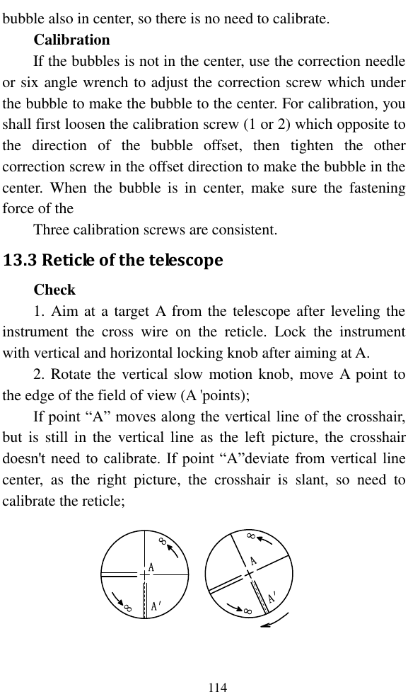
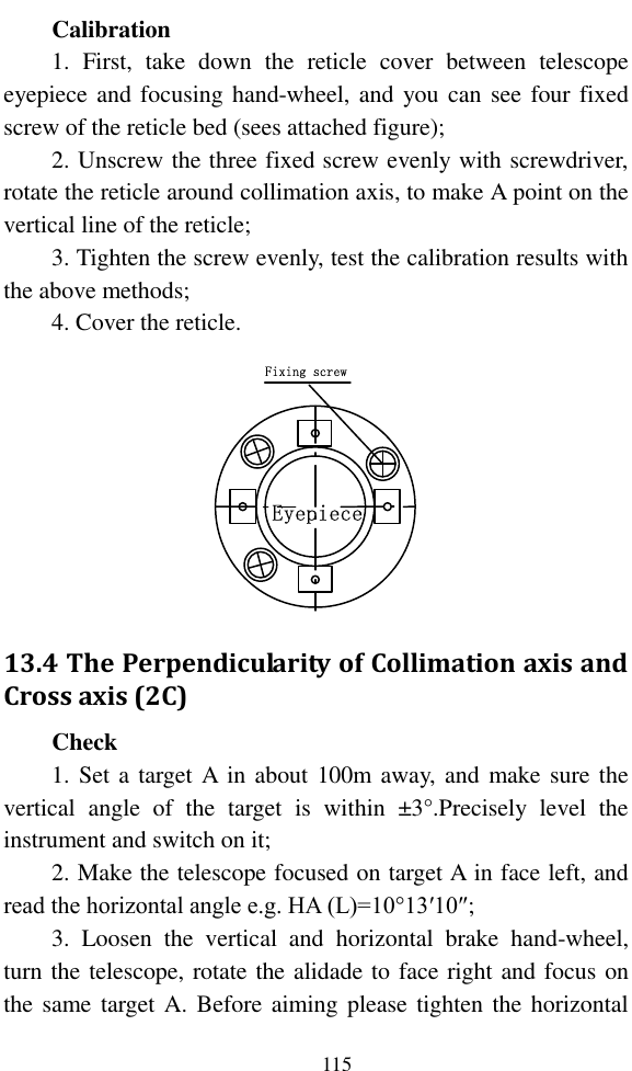
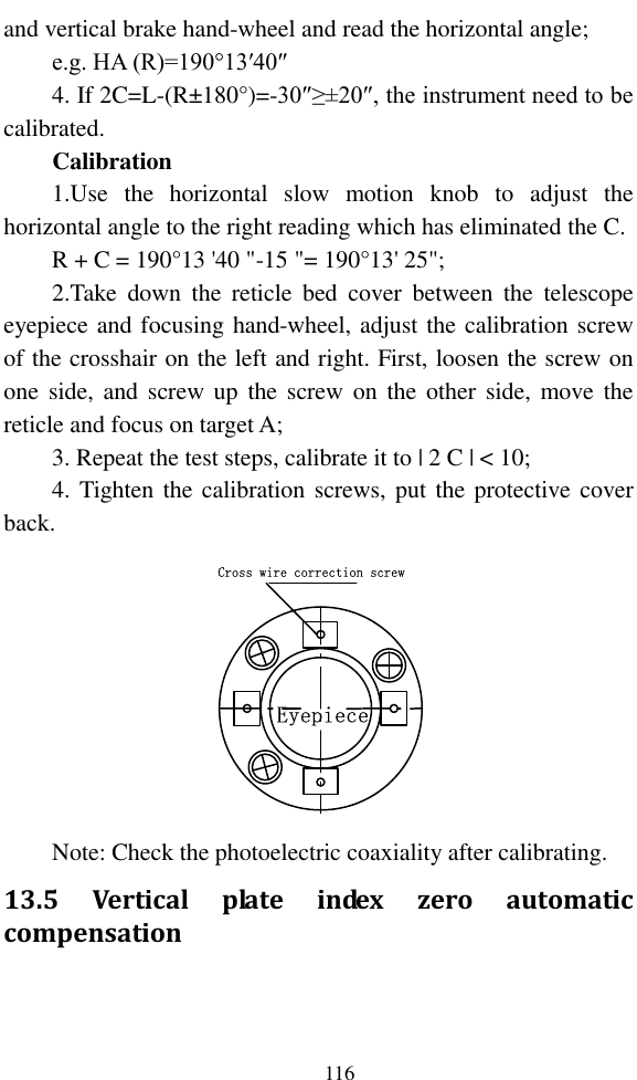
![119 optical plummet) or press key[★] to switch on laser plummet, move the white paper to make the cross in the center in the field of view (or laser flare); 3. Turn the feet screw, make the center mark of the plummet coincide with the cross center; 4. Rotate alidade, every turn of 90°, observe the contact ratio of the optical plummet and cross center; 5. When rotate the alidade, the center of the optical plummet always coincide with the cross center, there is no need to calibrate. Otherwise you should calibrate as the following methods. Calibration 1. Take down the screw cover between the optical plummet eyepiece and the focusing hand-wheel; 2. Fix the white paper with a cross, and mark the points when the instrument rotates 90°, as the figure shows A, B, C, D points; 3. Connect the diagonal points A、C and B、D with a straight line, the intersection name of the two line is point O; 4. Use the calibration needle to adjust the four calibration screw, to make the center mark of the plummet coincide with point O; Cross center on the groundACB0](https://usermanual.wiki/Hi-Target-Surveying-Instrument/HTSMINI/User-Guide-3281758-Page-131.png)