Hi Target Surveying Instrument HTSMINI total station User Manual Preface
Hi-Target Surveying Instrument Co., Ltd total station Preface
User Manual

Hi-Target Surveying Instrument Co. Ltd.
NAME: TOTALSTATION
MODEL:HTS-360R
The statements should be displayed in the user manual:
changes or modifications not expressly approved by the
party responsible for compliance could void the user’s authority
to operate the equipment.
This equipment has been tested and found to comply with
the limits for a Class B digital device, pursuant to Part 15 of the
FCC Rules. These limits are designed to provide reasonable
protection against harmful interference in a residential
installation. This equipment generates, uses and can radiate radio
frequency energy and, if not installed and used in accordance
with the instructions, may cause harmful interference to radio
communications.However, there is no guarantee that interference
will not occur in a particular installation.
If this equipment does cause harmful interference to radio
or television reception, which can be determined by turning the
equipment off and on, the user is encouraged to try to correct the
interference by one or more of the
following measures:
-- Reorient or relocate the receiving antenna.
-- Increase the separation between the equipment and
receiver.
-- Connect the equipment into an outlet on a circuit
different from that to which the receiver is connected.
-- Consult the dealer or an experienced radio/TV technician
for help.

1
Preface
Thank you for purchasing our HTS-360 Mini series total
station! This manual is your good helper, please read it before
operating the instrument and keep it properly.
Product Validation
In order to get our best service, please give the feedback
about the version, number, purchasing date of the instrument and
your valuable suggestions to us after you purchase our product.
We will attach great importance to every piece of advice
from you!
We will pay much attention to every detail of our products!
We will make great efforts to provide better quality!
Notice: We reserve the right to change the technical
parameters during updating and improving our products and we
may not announce you in advance. The Pictures in this manual is
for reference only, please in kind prevail.

2
Features
Rich Features--our total station carries abundant surveying
application, at the same time has the functions of data storage,
parameter settings and etc. It’s suitable for all kinds of
professional measurements.
Absolute code disc
Equipped with absolute code disc, the instrument can
measure after switched on .Even if reset the battery halfway, the
azimuth information will not be lost.
A high-capacity RAM Management
It serves an easy management for file system, including the
increase, deletion and transmission of data.
Non-prism distance measuring
With non-prism distance measuring, this series total station
can be directly to all kinds of material, different colors of objects
(such as the structure of the walls, poles, wires, cliff wall,
mountain, clay, wood, etc.) for long, fast, high precision
measurement .This function is especially for the measurements
of targets that cannot be accessed.
Special measurement program
Our total station is equipped with some special
measurement program to meet the needs of professional
measuring, such as Remote Height (REM) Measurement, Offset
Measurement, MLM (MLM Measurement), Resection, Area
measurement calculation, Roadway design and staking out.
Changeable eyepiece
As the eyepiece is changeable, it is convenient to be
equipped with diagonal eyepiece, which makes it easy to
observe the zenith direction high-rise buildings

3
Laser plummet
Easy to direct the station point and free station
Notice:
Don’t look directly into the sun with the objective lens;
Do not leave the instrument at extreme temperatures (too
high or too low) or use it when thermal shock;
When you don’t use the instrument, should load it in the
box and place it well-ventilate and dry place ,and pay attention
to the shock-proof ,dust-proof and damp-proof;
In order to get good precision, you should leave the
instrument in the box to make it adapt the environment when
there is a great difference in temperature between working
environment and storage environment
The battery should be unloaded and charged once a month
for extending its life. If not ,the instrument will not be used for
a long term.
When transporting the instrument, you should store it in
box and be careful to avoid extrusion, collision and violent
vibration. A soft mat around the boxes is required for
long-distance transport.
When setting the instrument, it’s better to work with
high-quality wooden tripod for stability and measurement
accuracy.
In order to improve the precision of Non-Prism
measurement, please keep the object lens clean. When cleaning
exposed optical devices, please wipe them gently with absorbent
cotton or lens paper only.
After using instrument, please sweep away the surface dust
with flannelette or hairbrush. Do not switch on the device when
it has got wet by rain. Please wipe it dry with clean soft cloth

4
and put it in ventilated place for a period time to make the
equipment fully dry before using and packing.
Please check out that the indicators, functions, power
supply, initial setting and correction parameters of the instrument
meet the requirements before operating.
If discovering the abnormal function of the instrument,
non-professional maintenance personnel are not allowed to
disassemble the instrument without authorization, in case of any
unnecessary damage.
As a safety precaution, do not aim at eyes directly when
using the instrument.
Security Guide
Please pay attention to the following security matters when
using the instrument with non-prism.
Warning:
Total station is equipped with rangefinders with laser level
3R/IIIa, which is recognized by the following logo recognition
at the horizon-axis locking knob” of the instrument, saying
“Class 3A Laser Product”. The Total Station is classified as
Class 3R Laser Product and abides by the class of Laser Product
according to IEC Standard Publication 60825-1:2001.
For Class 3R/IIIa Laser Product, its emitted laser with
wavelength between 400nm and 700nm can be at most 5 times
of that of Class 2/II.
Warnings:
Never star at laser beam constantly, it could cause
permanent eye damage.
Precautions:
Do not see directly into laser beams nor point laser to
persons.
The reflected beam is the necessary for the instrument

5
measurement signal.
Warnings:
It’s dangerous to use Class 3R Laser instrument improperly.
Precautions:
In order to avoid causing damage, the proper precautions
should be taken for you and control well the distance (in
accordance with the standard “IEC60825-1:2001”) that may
occur hazards.
The following is the main part of the explanation of the IEC
Standard Publication:
Class 3R Laser Products are used in outdoors and on
building site (with non-prism measurements).
The personnel who is specially trained, qualified and
authenticated are allowed to stall, adjust and operate these laser
instruments.
b. Set up corresponding laser warning signs in the use of
area range.
c. Prevent anyone from looking directly into laser beams or
watching the laser beams with optical device.
d. In order to prevent laser damage to people , the laser
beams should blocked at the end of the working route. In the
limited area (★Hazardous distances) where the laser beams
through ,the laser beams should be terminated when there are
some activities.
e. the route which laser beans through must be set higher or
lower than the sight of people.
f. When the instrument not in use, please make it
safekeeping and storied. Unauthorized person should not use it.
g. To prevent exposure to laser beam accidentally, such as
mirrors, metal surfaces, windows, be careful as the flat surface
of the mirror and concave mirror.

6
*The hazardous distance refers to the maximum distance
which is from beginning of the laser beams to the laser beam
weaken until it does not harm people. The built-in rangefinder
products equipped with Class 3R/IIIa laser whose hazardous
distance is 1000 meters (3300feet), and in the distance, the
strength weakens to a Class 1 laser (sightseeing beam eyes
couldn't hurt).

7
Content
1. Use of instrument.............................................................. 1
2. Names and functions of the components ................. 2
2.1 Names of the components ........................................... 2
2.2 The information of the displays ................................ 4
3. Initial setup ......................................................................... 8
3.1 On & Off .............................................................................. 8
3.2 Set up the tilt correction of horizontal and
vertical angles .................................................................................... 8
3.3 Settings of star [★] key. ............................................... 9
3.4 Setting for measurement parameters ..................10
3.4 Settings of hot key[▪]. ..................................................11
3.4.1 Input of target height .....................................11
3.4.2 Settings of temperature and pressure ....12
3.4.3 Inputs of Note. ..................................................13
3.5 Select data files ................................................................14
4. Preparations before measurements ........................ 15
4.1 Unpacking and storing instruments......................15
4.2 Set up the instrument .................................................15
4.2.1 Using plummets to center and level (align)
.....................................................................................................15
4.2.2 Using centering device to center ...............17
4.3 Loading and unloading of battery ..........................18
4.4 Reflecting Prism. ...........................................................19
4.5 Loading and unloading of the pedestal .................19
4.6 Adjusting eyepiece lens of the telescope and
aiming the target. ...........................................................................19
4.7 Entering letters and numbers ..................................20
4.8 Retrieve points ...............................................................23
4.9 Measured point .............................................................25

8
4.10 Retrieve code ................................................................25
4.11 Record point data .......................................................26
4.11.1 Record data without displaying...............26
4.11.2 The display of saved data ...........................27
4.12 Basic measurement ..................................................27
5. Angle .................................................................................... 31
5.1 Set 0 ....................................................................................31
5.2 Set HA ................................................................................32
5.3 Hold HA .............................................................................32
5.4 HA Repetition .................................................................33
6. Setup Station ..................................................................... 35
6.1 BS coord. ...........................................................................35
6.2 BS angle .............................................................................37
6.3 Resection ..........................................................................38
6.4 Quick ..................................................................................40
6.5 Remote BM ......................................................................40
6.6 BS check ...........................................................................42
6.7 View STN ..........................................................................42
7. Stake out ............................................................................. 43
7.1 S-O ang.&dist. .................................................................43
7.2 S-O coord. .........................................................................44
7.3 S-O equidist. ....................................................................45
7.4 S-O line pt. .......................................................................46
7.5 S-O line ..............................................................................47
7.6 The result measurement of the staking out
above. ..................................................................................................48
8. Program ............................................................................. 51
8.1 Projection .........................................................................51
8.2 ARC measurement .......................................................53
8.2.1 Define of arc ......................................................54
8.2.1.1 Define arc with two endpoints and

9
azimuth...........................................................................54
8.2.1.2 Define arc by radius and azimuth .........55
8.2.1.3 Define arc with radius and arc length .55
8.2.2 Arc measurement ............................................56
8.3 MLM ...................................................................................57
8.3.1 MLM (A-B,A-C) .................................................57
8.3.2 MLM (A-B,B-C) .................................................58
8.4 REM (Remote height) .................................................58
8.5 Vertical plane measurement ....................................60
8.6 Bevel ..................................................................................61
8.7 Area & Girth ....................................................................63
9. Offset ................................................................................... 65
9.1 Single-Distance Offset Mode .....................................65
9.2 Angle offset Mode ..........................................................67
9.3 Double-Distance Offset Mode .................................68
9.4 Horizontal distance offset Mode .............................70
9.5 Column Offset Mode .....................................................71
9.6 Slope Distance Offset Mode .......................................73
10. Data management. ....................................................... 75
10.1 View file data ................................................................75
10.2 view known coordinate. .........................................77
10.3 Input known coordinate .........................................78
10.4 Code manager ..............................................................79
10.5 Clear code .......................................................................80
11 Menu .................................................................................. 81
11.1 File manager .................................................................81
11.2 Setting .............................................................................83
11.2.1 Angle Setting ...................................................83
11.2.2 Distance setting .............................................84
11.2.3 Coordinate setting ........................................85
11.2.4 Unit setting ......................................................86

10
11.2.5 Communication setting ..............................86
11.2.6 Other settings .................................................87
11.2.7 Factory reset ...................................................87
11.2.8 Upgrade .............................................................88
11.3 Data management .....................................................90
11.4 Import and Export.....................................................91
11.4.1 Export to PC ....................................................91
11.4.2 Export to U disk ............................................92
11.4.3 Import coordinate from PC ......................93
11.4.4 Import coordinate from U disk ...............94
11.4.5 Import code from PC ...................................95
11.4.6 Import code from U disk ............................96
11.4.7 Mini USB connect .........................................96
11.5 User key definition .....................................................97
11.6 Calibration ....................................................................99
11.6.1 Adjusting index error(I.E) ........................99
11.6.2 Input the instrument constant ............. 100
11.6.3 Calibrate the tilt X ...................................... 101
11.7 Date/Time ................................................................. 102
12 Roadway ........................................................................ 104
12.1 Road file manager ................................................... 104
12.2 Horizontal alignment file...................................... 105
12.2.1 Element method ......................................... 105
12.2.2 The intersection method ........................ 108
12.3 vertical alignment ................................................... 109
12.4 Staking out Roadway ............................................. 110
13. Adjustments and Corrections ................................ 113
13.1 Tubular Level ............................................................ 113
13.2 Circular Level ............................................................ 113
13.3 Reticle of the telescope .......................................... 114
13.4 The Perpendicularity of Collimation axis and

11
Cross axis (2C) ............................................................................. 115
13.5 Vertical plate index zero automatic
compensation ............................................................................... 116
13.6 Vertical index error (angle i) and set vertical
index 0 ............................................................................................. 118
13.7 Centering device ...................................................... 118
13.8 Addictive constant (K) ........................................... 120
13.9 The parallelism of collimation axis and
photoelectricity axis ................................................................... 121
13.10 Non-prism ranging .............................................. 122
14. Technical parameters .............................................. 123
Appendix A File format introduction (Sunway) .... 126

1
1. Use of instrument
The total station is such an instrument that measures the
azimuth and distances to destination and can calculate the
destination point coordinates automatically. It plays an important
role in the economic construction and national defense
construction. General Survey, exploration and mining of
minerals, the construction of railways, roads, bridges, irrigation,
urban planning and construction is driven by electronic total
station measurements. In the building of national defense, such
as battlefield preparations, harbor, forts, airfields, bases and
military construction projects, and so on, must be based on a
detailed and accurate geodetic. In recent years, electronic total
station is a large precision engineering, shipbuilding and aviation
industries and other aspects of effective tools for precise
positioning and installation.
The series total station is equipped with absolute code dial
system, integrated-circuit-control-board ranging item and
microcomputer for measurements of angle and distance and for
calculation, display, depositing and etc. It can exhibit horizontal
and vertical angle, slope and horizontal distance and altitude
difference simultaneously. Furthermore, it can be set to measure
under different mode (e.g. Angle mode, Distance mode).It is
even designed for you specializing in construction projects with
non-prism ranging. The non-prism ranging can be
comprehensively used in measuring three-dimensional
coordinates, position determination, remote elevation
measurement (REM), verticality, pipeline positioning,
cross-section measurement etc. It also meets requirements for
trigonometrical control survey, topographic survey, cadastre and
real estate survey.
2
2. Names and functions of the components
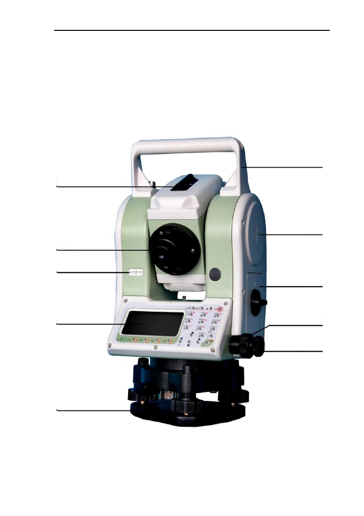
2.1 Names of the components
Handle
Horizontal center
Coarse
sighting device
Eyepiece
Number
Battery box
Display Horizontal
clamping screw
Horizontal
tangent screw
Base
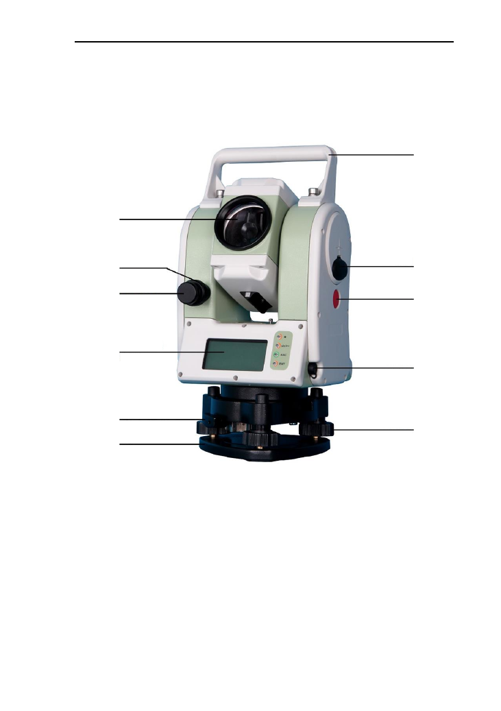
3
Handle
USB port
Fast measuring key
RS-232
Communication port
Leveling screw
Objective lens
Vertical clamping screw
Vertical tangent screw
Display
Locking screw
Base
4
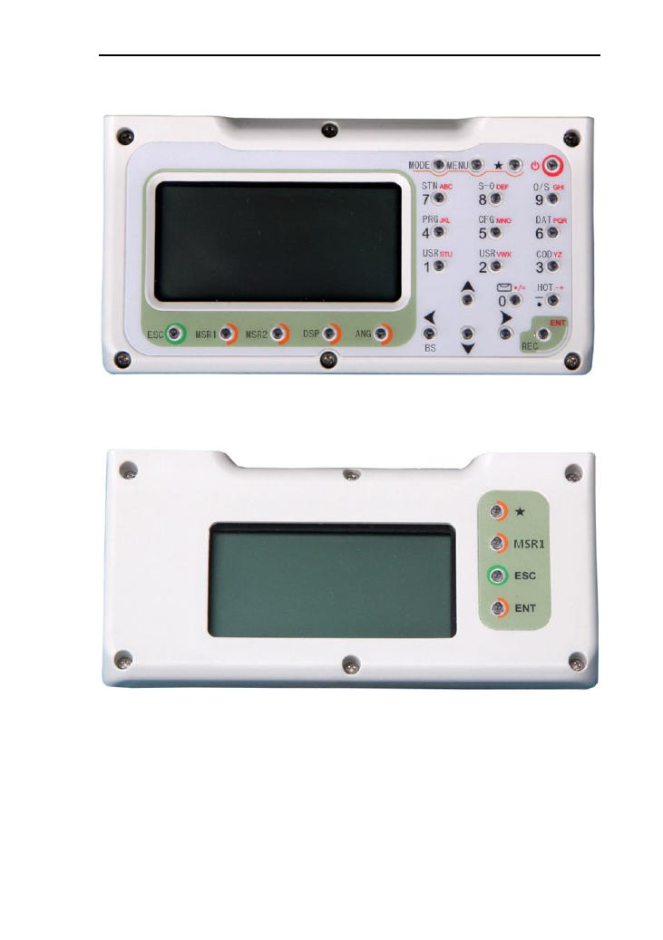
2.2 The information of the displays
The sketch of display and keyboard in face left
The sketch of display and keyboard in face right

5
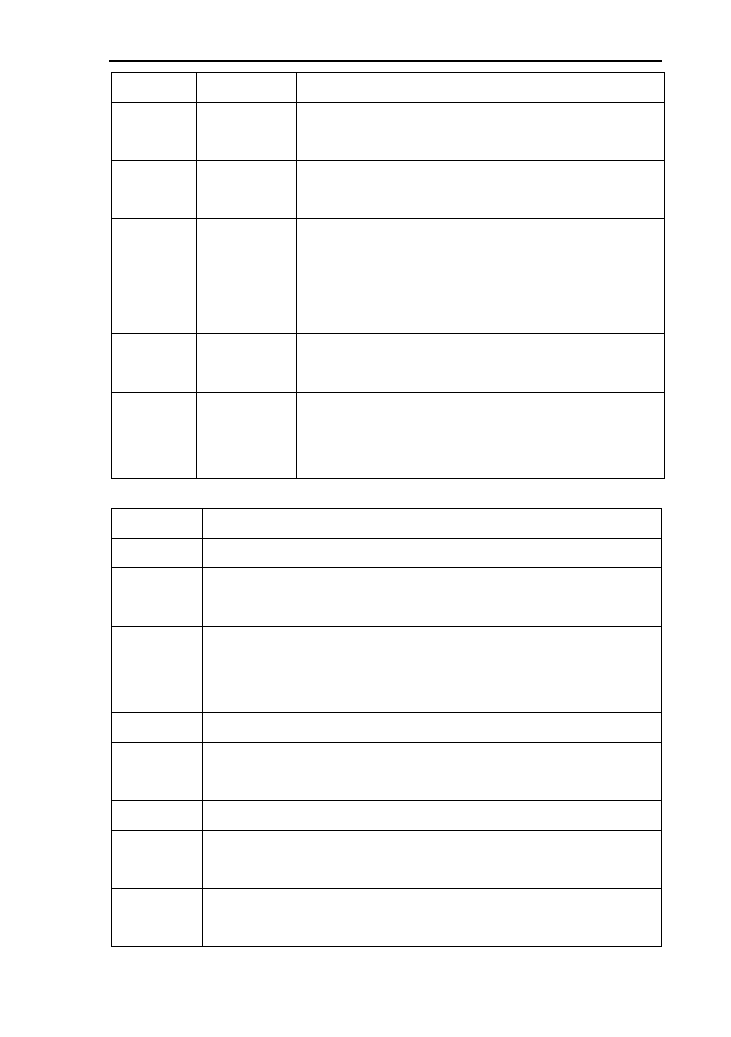
Symbols on the keyboard
Keys
Name
Function
Power
Power on/off
MSR1
MSR1
In the basic interface,measure distance;
In the other distance,it indicates the function
upon to the soft key
MSR2
MSR2
In the basic interface,measure distance;
In the other distance,it indicates the function
upon to the soft key
DSP
DSP
Under the basic measurement interface,down
to the next page.
Under the other interface this soft key, it
indicates the function upon to the soft key
ANG
Angle
Under the basic measurement interface, enter
into the angle menu.
Under the other measurement interface, it
indicates the function upon to the soft key.
MODE
Mode
Switch the input between number and alphabet
in the input dialogue. (number--letter)
MENU
Menu
Under the basic measurement interface, enter
into the Menu.
★
Star key
In any interface, you can enter the star key
interface under any interface. You can set the
contrast, lighting compensator , parameters of
distance measuring and file selecting .etc.
ENT
Enter
Receive and save the data input in the dialogue
and end the dialogue.
Save the current measurement data under the
basic measurement interface.
ESC
Exit /quit
End the dialogue box without saving the
6
input,and return to the previous step
◄►
Left /right
change the option in the select box
Data list page
▲▼
Up /down
Move the Cursor up and down in order.
Turn the page under the basic measurement.
0~9
Number
Input number and characters and select one of
menu.
“0”: Enter the electronic bubble interface under
the basic measurement.
·
Symbols
Enter symbols, decimals and signs;
Enter the interface for input height.
The side
key
Fast
measurem
ent key
This function is equal with it of the key
[MSR1]. It works just in the measurement
interface, and does not work in the others.
Symbols on the display
Symbols
Indication
Vz
Zenith Mode
Vo
The mode that the vertical is displayed as zero when the
telescope is level in normal
Vh
Vertical angle Mode (it is 0°00′00″when the telescope is
level. The angle of elevation is positive and the angle of
depression is negative.)
V%
Slope Mode
HR
Horizontal angle (right angle). dHR means the angle
difference of setting out.
HL
Horizontal angle (anticlockwise increment)
HD
Horizontal distance. dHD is to stake out horizontal distance
difference.
VD
Elevation difference. dVD is to stake out difference between
elevation differences.
7
SD
Slope distance. dSD is to stake out differences between
slope distances.
N
Northing. dN is to stake out differences between
north-coordinates.
E
Easting. dE is to stake out differences between
East-coordinates.
Z
Elevation. dZ is to stake out differences between
Z-coordinates
m
Unit in meters (metric units)
F
Units in feet
f
Units in American feet
M
Units inMIL
g
Units inGON
The maximum character length and range of data
Coordinates:-99999999.999——+99999999.999m
Instrument height:-999.999——+999.999m
Target height:-999.999——+999.999
Distance:0——+99999999.999m
Point name:Maximum of 8 characters
Code:Maximum of 8 characters
Coordinate:Maximum of 14 characters

8
3. Initial setup
3.1 On & Off
Press and hold the key ‘On/Off’ (the buzzer remains buzzer)
until the screen displays pictures. The instrument is now
switched on.
After self-checking, the instrument enters Angle Mode
automatically (see details in 5. Angle Mode for details)
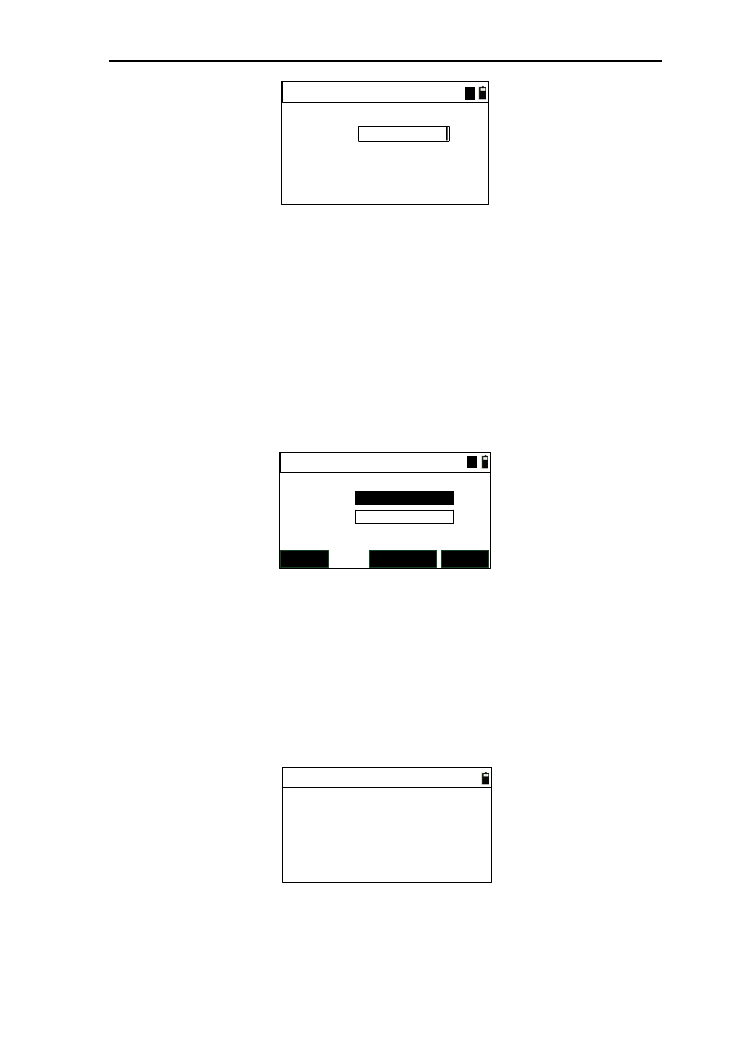
Pressing power key will leads to a dialogue box. Press
[ENT] to turn off the instrument.
3.2 Set up the tilt correction of horizontal and
vertical angles
When the tilt (inclination) sensor is on, the instrument will
display the automatic correction value for the vertical angle
caused by not strictly level. In order to ensure the accuracy of
the angle measurement, try to use tilt sensor whose display can
be used to level the instrument better.
If displaying ‘Tilt over!’ in the ‘Vz’ column, it indicates that
the instrument beyond the range of the automatic compensation,
and it needs to be leveled by adjusting foot screw.
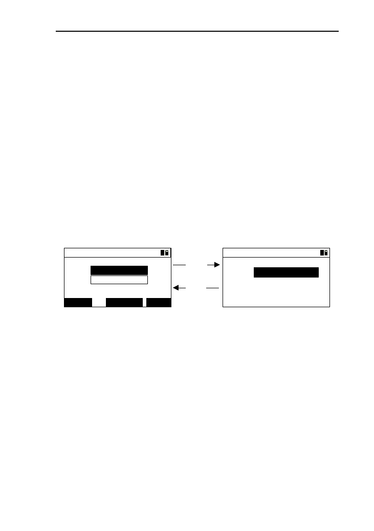
Operations :under the basic measurement interface, press
the key [0],then enter the electric bubble interface as follow:
Bubble
DIGIT
↔
D AS AOFF
ON
ON
↔
1)The horizontal arrow “↔” will displays “OF” by
9
press the key [S A], and the data of “Tilt Y” will display zero
by press [DIGIT] when the instrument is equipped with
single-axis compensator;
2)Press [OFF] to close the compensator;
3)Press [S A] to open the compensator of the vertical
direction and close the compensator of the horizontal
direction;
4)Press [D A] to open the compensator of the two
directions.(For the instrument equipped with dual-axis
compensator);
5)Press [DIGIT] to display the value of compensator,
which is real-time refresh, and the button of [DIGIT] is
changed [GRA.] .Press the [GRA.] to return to the graphical
display interface;
6)Press [ENT] or [ESC] to come back to basic
interface.
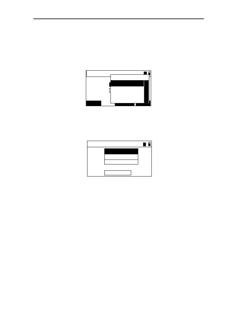
3.3 Settings of star [★] key.
Except for the menu interface, you can press [★] to enter
the following interface.
Shot cut
Beep:
-
Contrast:
+LASERLIGHT
OF ►
4 ▲ ▼
The settings of star[★] key as below:
1) Switch key for buzzer each time you press the [►]
switch on or off the buzzer circularly;
2) Contrast adjusting: adjust the contrast of display by
10
pressing the key [▲] or [▼];
3) Backlight: each time you press the key [Light], the
backlight of display can switch between the brightness (for three
levels) and off circularly;
4)Laser: Each time pressing the key [LASER] can switch
on or off the laser;
5) laser plummet: you can increase the laser plummet
brightness until the brightest by press [+],and you can also
press [﹣] to decrease the laser plummet brightness until off it.
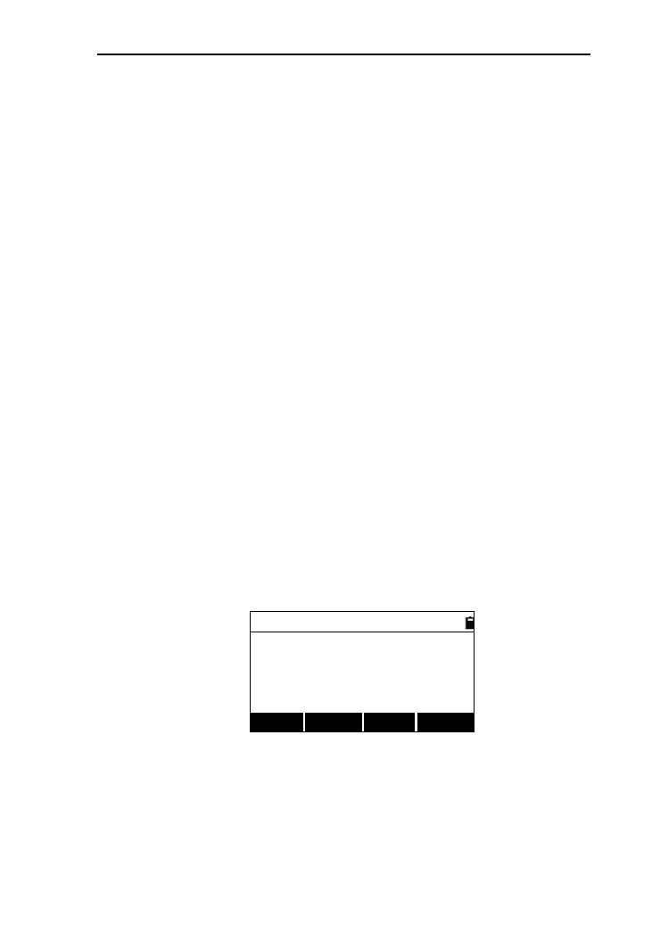
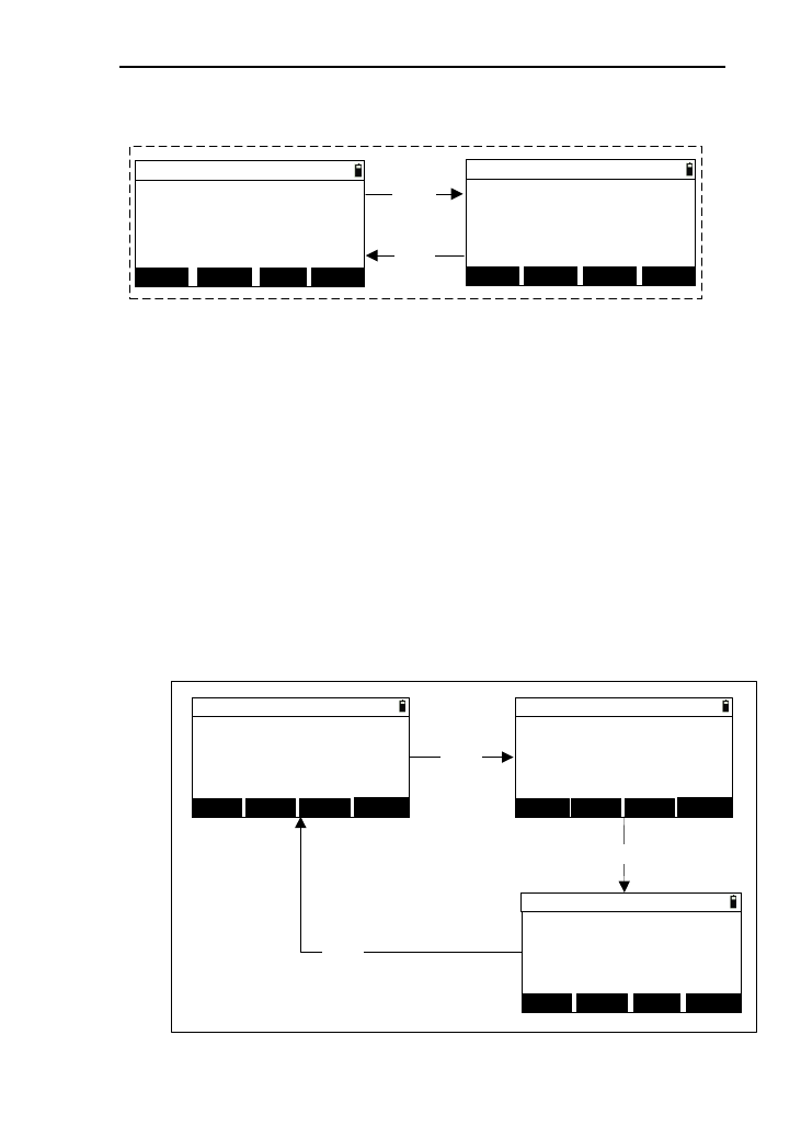
3.4 Setting for measurement parameters
You can press the [5] to set the measurement parameters
under all measurement interfaces.
-------Config------
1.[MSR1] Config
2.[MSR2] Config
Reflect:
PSM:
Mode:
Meas Setting-MSR1
Count:
Record:
0
3
ENT
▲
▲
Track
▲
▲
Prism
▲
▲
This series total station is equipped two measurement
keys,[MSR1] and [MSR2] and each of them is equipped with
measurement parameters. Whichever you select, you can equip
the measurement parameters under the menu of “Config”
interface. Here,as an example to the key [MSR1]
1) You can press the key [ENT] or [▼] to move the focus down
and also press [▲] to move the focus up when complete to
set one parameter;
2) You can change the options by pressing the key [◄] or [►];
3) After the last setting completed, you can press [ENT] to save
the settings, and return to the last interface;
4) Reflect: you can select “prism”, “NP”(for Non prism
11
instrument) , “RB’(reflector board);
5) PSM: Prism constant .Generally as “0” or “30”,if the prism is
special, you need to input itself constant value;
6) Mode: Distance measurement mode .You have four options to
select, which are “Single”, “Rept.”, “Avg.”(Set by “count”),
“Track”(Fast but low accuracy) . The “Single” measurement
and “Avg.” measurement can be ended automatically after a
successful measuring. But if you want to end the “Track” and
“Rept.” measurement, you must press the key [ESC];
7) Count: Times of the “Rept.” measurement. The range is “1” to
“9”;
8) Record: to set the mode of storing data under the basic
measurement. You can choose “ENT” (press [ENT] to enter
the “rec. data” interface.), “AUTO” (record the measured
data automatically after a successful measurement),
“NO”(won’t record the measured data , even though pressing
[ENT]).
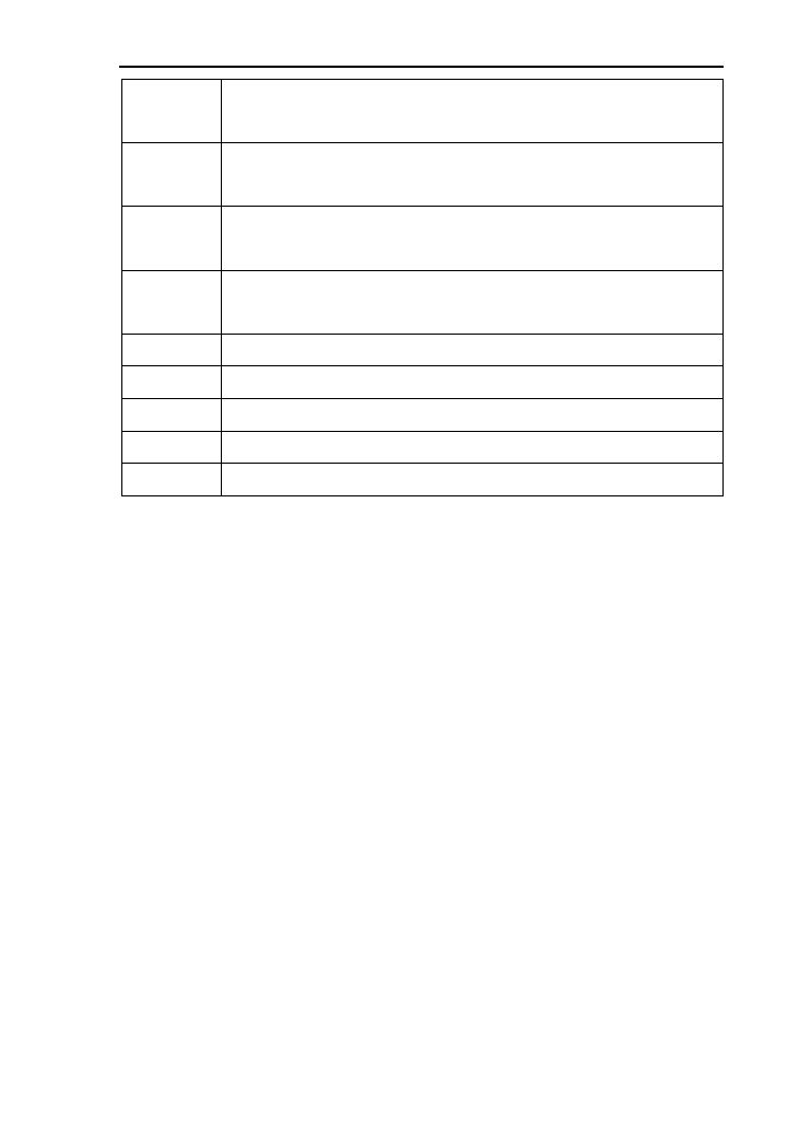
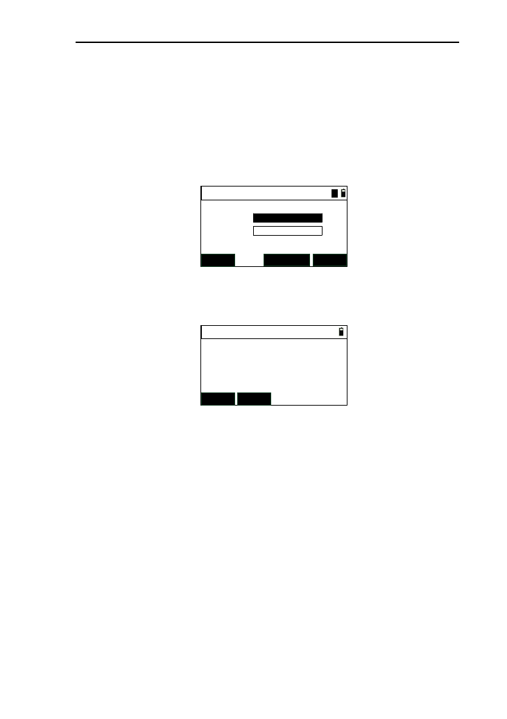
3.4 Settings of hot key[•]
Under the basic measurement interface, you can press the
hot key [▪] to enter the “Hotkey” interface.
----Hotkey----
1.T.H
3.Note
2.Temp-Press
3.4.1 Input of target height
If you want to change the current system default of target
12
height, you can apply this function.
Under the “Hotkey” interface, press the key [1] to enter the
“Input T.H” interface.
Input T.H
T.H:m
1) After you input the target height , press [ENT] to save
the target height to the system parameters .when you enter
another interface which displays the target height ,the value will
be the system default until you change it;
2) The range of input is “-999.999” to “999.999” .if out of
range, it will prompt you;
3) Press [ESC] to come back to the “Hotkey” interface with
not saving the value of target height.
3.4.2 Settings of temperature and pressure
When measuring distance, the measured value can be
influenced by the atmosphere. In order to reduce the influence,
an atmospheric correction parameter (which is calculated by
current temperature and atmospheric pressure values) is needed.
The standard atmospheric value of this series Total Station
(i.e. the atmospheric conditions when the correction is zero)
Atm: 1013 Pa
Temp:20℃
The calculation of atmospheric correction
PPM= 277.825- 0.29434P/(1+0.003661T) (ppm)
In the formula:
PPM: correction coefficient (unit: ppm)
13
P: atmospheric pressure (unit: hPa)
T: temperature (unit:℃)
Under the “Hotkey” interface, press [2] or press [ENT]
when the focus is at “2.Tem-Press” to enter the “Input TP”
interface.
Input TP
20
Temp:
Press: 1013
PPM:
℃
hPa
1
0
1) Temp: temperature value, only need integer part,the
range is “-30℃” to “60℃”;
2) Press: Atmospheric pressure ,only need integer part,
the range is “500hpa” to “1400hpa”;
3) PPM: the value will be changed when the temperature
or pressure changed;
4) Press [ESC] back to the “Hotkey” interface without
saving the changed value.
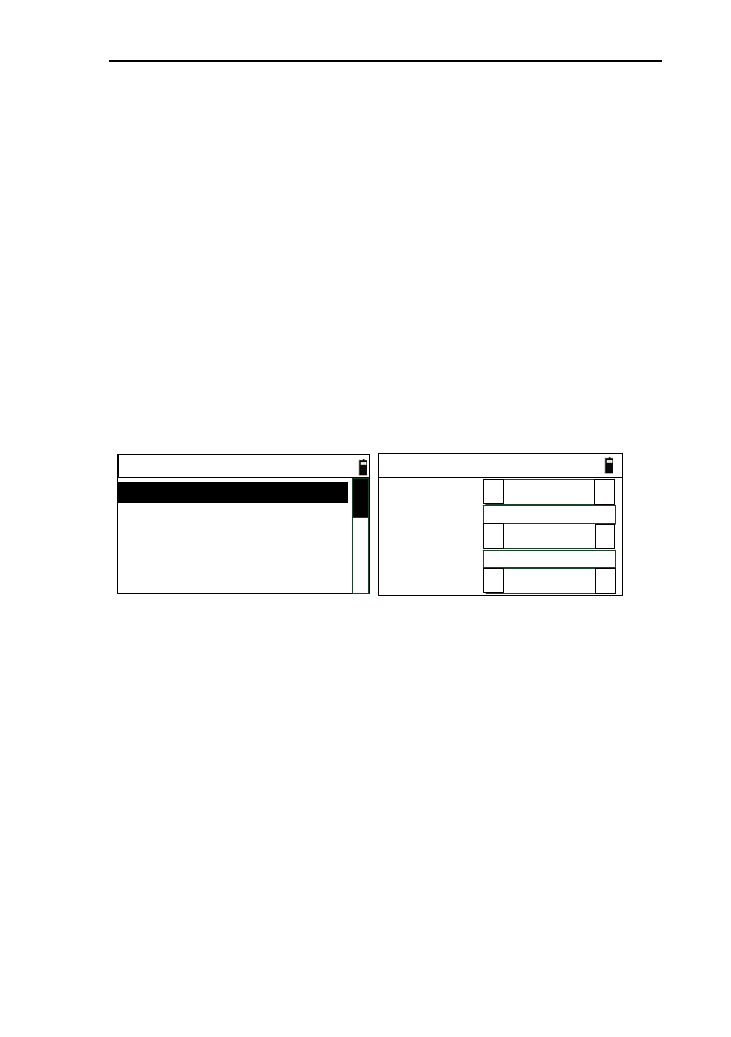
3.4.3 Inputs of Note.
If you want to note simple information, this function can
help you. Under the “Hotkey” interface, press [3] or press [ENT]
when the focus is at “3.Note” to enter the “Input Note” interface.
Input Note
*[ENT] record
1
1) You can input notes by pressing [Mode] to switch the

14
input mode. Maximum of 50 characters;
2) After inputting the notes, press [ENT] to record it and
then a prompt box “NOTE rec. OK” appears and back
to the “Hotkey ” interface;
3) The information of note is recorded to the current
measurement file;
4) You can press [ESC] to return to the “Hotkey”
interface under the “Input Note” interface.
3.5 Select data files
The instrument needs large data and creates large data when
it is operated. These data are storied in the system files as a file
form. It’s a good habit that select measurement files what you
need before working, otherwise, your measured data can’t be
saved.(see reference in “11. File management”.)

15
4. Preparations before measurements
4.1 Unpacking and storing instruments
Unpacking
Lay down the box gently with the top side facing up. Open
the lock and take out the instrument.
Storage
Cover the telescope cover. Make sure that the vertical
clamping screw and the level bubble face upwards. Lay down
the instrument into the box (with objective lens of the telescope
facing downwards.). Tighten the vertical clamping screw gently
and cover the box, then Lock the box.
4.2 Set up the instrument
Reference for operation:
Install the instrument onto the tripod gently, then level and
center the instrument to ensure the accuracy of the measurement
result.
4.2.1 Using plummets to center and level (align)
1) Set up the tripod
① Position tripod legs so that the plummet is aimed to the
ground mark point. Turn the focusing ring of the optical
plummet to focus;
② Make sure that the center of the tripod top is right above
the station;
③ Stamp the tripod on the ground with your feet.
2) Install the instrument onto the tripod
Mount the instrument on the tripod head. Support it with
one hand, and tighten the centering screw on the bottom of the
16
unit to make sure it is secured to the tripod.
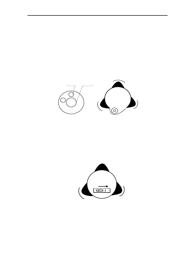
3) Using the circular level to level the instrument coarsely
① Twist and adjust the two leveling screw A and B on the
bottom of the instrument until the bubbles of the circular level
moves to the line perpendicular to the center line the screw A
and B;
② Twist and adjust leveling screw C to move the bubble to
the center of the circular level.
center
buble
Screw C
Screw B
Screw A
4) Using the plate level to level the instrument precisely
① Loosen the horizontal locking screw and turn the
instrument around until the plate level is perpendicular to a line
shaped with screws A and B. Adjust the screws A and B to make
the bubble in the center of the level;
Screw C
Screw B
Screw A
② Turn the instrument approximately 90° and adjust screw
C until the bubble in the center of the level;
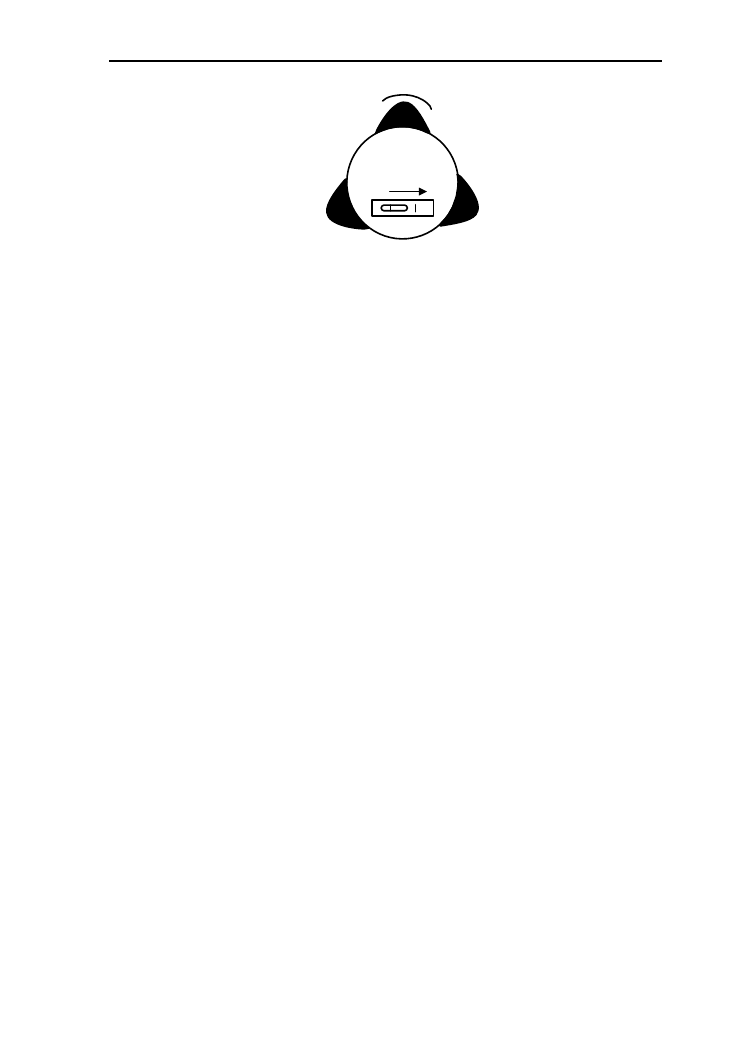
17
Screw C
Screw B
Screw A
③Turn around the instrument 90°again. Repeat above steps
until the bubble remains in the center of the plate level even
though the instrument is rotated to any position.
4.2.2 Using centering device to center
1) Set up the tripod;
Open the tripod. Make sure that the three feet of
the tripod are approximately equal in distance from the
center and that the top is leveled. Screw up the three
locking screw;
Make sure that the center of the tripod top is right
above the station;
Stamp one foot on the ground with your feet.
2) Install the instrument gently on the top of the tripod
and screw up the screw connection. Open the laser
plummet through star (★) key to aim at the station
precisely;
3) Using circular level to level the instrument coarsely;
4) Using tubular level to level the instrument precisely;
5) Precise centering and leveling;
According to the observation of center device, loose the
connection screw slightly and shift the instrument horizontally
(mention that do not turn around the instrument)until the
instrument aims at the station precisely.
18
Repeat the steps above until the instrument aims at the
station precisely.
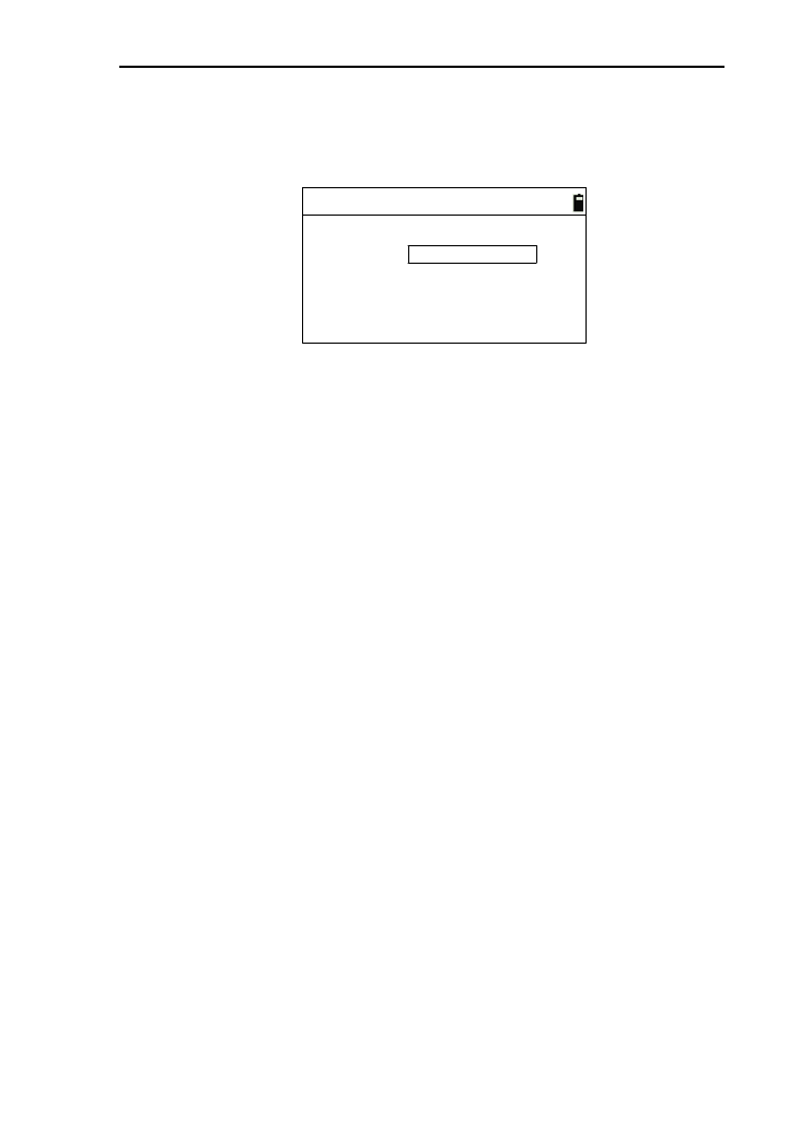
4.3 Loading and unloading of battery
The information of the battery
--Full battery, operation is available.
--Just appearing this information which means the battery
can support the instrument for another 4 hours.
--The battery is lower, and it’s better to replace.
--Measurement is impossible, and it’s necessary to replace
and recharge battery.
Notes:
◆The working time of battery will be effected by many
factors, such as ambient temperature, recharging time,
recharging and discharging times. For safety, we suggest you
recharge the battery full or prepare several full batteries before
operation.
◆The battery symbol only indicates power capability for
current measurement mode. The power consumption in distance
measurement mode is more than in angle mode, if the instrument
enters into distance measurement mode from angle mode, the
power maybe auto-off because of lower battery.
Notes for loading/ unloading batteries:
▲You should switch off the instrument before unload the
battery.
Notes for charging:
▲Though the charger is designed with overcharge
protection circuit, one must unplug the charger after finished
charging.
▲Suitable temperature range for charging is between -45℃
and +45℃. Charging process may be abnormal if being over the

19
temperature range.
▲A battery can be recharged for 300-500 times.
▲A monthly recharging is required if the instrument is not
used for a long time.
4.4 Reflecting Prism.
When measuring distance with prism mode, a reflecting
prism must be set at the target site. You can connect the prism to
the base, and then connect the base onto the tripod .you can also
set the prism onto the centering rod. There are single-prism
group and three prism group available on the market, so you can
select them according to your requirements.
4.5 Loading and unloading of the pedestal
Unloading
Unload the base by loosening the locking screw on the base
with a screw driver and anti-clockwise turn the screw around
180°.
Loading
Put the three fixed feet of the instrument into the
corresponding holes to make the instrument on the base. Turn
the clamping screw clockwise 180° to lock the instrument. Then
tighten the screw with a screw driver.
4.6 Adjusting eyepiece lens of the telescope and
aiming the target.
How to aim at targets?(only for reference)
1) Aim at the bright sky with the telescope and adjust the
eyepiece to focus until a sharp image of the cross wire forms;
2) Aim at the target with the cross center in the coarse
sighting device on the top of the lens. Your eyes should keep a
20
proper distance (about 200mm) away from the sighting device;
3) Obtain a sharp image of the target on the reticule with
the focusing screw. If optical parallax appears when angle of
view changed, the focus or the diopter of the eyepiece may be
unadjusted. For precision concerns, please adjust the eyepiece
focus to eliminate the optical parallax carefully.
4.7 Entering letters and numbers
This series total station has been equipped the key [Mode],
which can be convenient to switch the input mode between
letters and numbers.
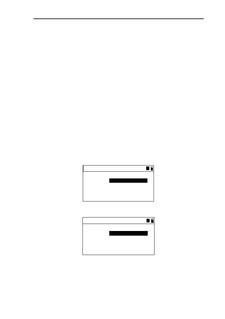
● Input letters
Example 1: Take inputting code for example, which needs
to input “Co1” in the edit box
1) Press [Mode] to switch to the mode of inputting letters.
There is a symbol displayed as “A” beside battery;
Input code
Code:
A
2) Press [1], then, “S” displays in the edit box;
Input code
S
Code:
A
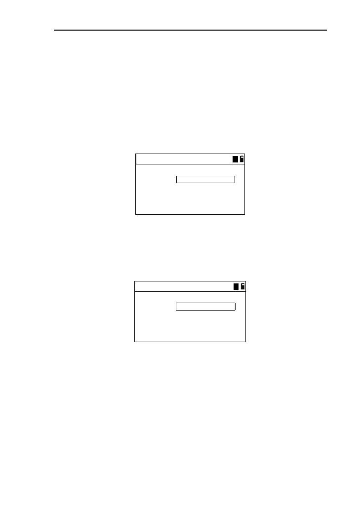
3) Wait 0.3 seconds, then press [1] again, “T”displays in
the edit box;
4) Wait 0.3 seconds,then press [1] again, “U”displays in
the edit box;
21
5) The interval of pressing the key [1] twice is not over
0.3 seconds .If over,another letter will be input. If
press the key [1] constantly, it will be circular between
“S” “T” “U” “1” “S”. The operation of the
other number keys (“0~9”) is as same as it of the key
[1];
6) Press the key [5] constantly again, “CO” displays in
the edit box;
Input code
CO
Code:
A
7) Press [Mode] to switch to the mode of inputting
numbers. There is a symbol displayed as “1” beside
battery;
8) After press the key [1],the interface is as follows:
Input code
CO1
Code:
A
9) Pressing [◄] can delete the character in the front of
cursor;
10) Pressing [►] can move the cursor circularly. When it
moved to the last, comes back to the first.
● Input numbers
Example 2: Take Inputting target height for example, which
needs to input “1.562” in the edit box.
1) Because the target height can’t be letter, the inputting
mode will default to number “1”, and can’t be
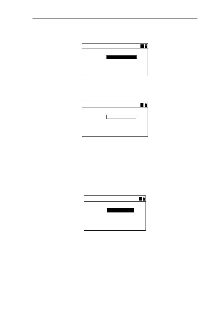
22
switched to the letter mode “A”. The interface is as
follows;
Input T.H
T.H:m
1
2) The order of the keys:[1]→[·]→[6]→[5]→[2];
3) The result is shown below:
Input T.H
1.652
T.H:m
1
4) After completing the input, press [ENT] to record the
input and end the edit box;
● Input angles
Example 3: Enter the “Input Angle->Set A” interface of
angle menu, which needs to input “123°45′56” in the edit box of
“HR”.
Input Angle->Set A
HR:
1
*[ENT]to set A
1) The order of the keys:[1]→[·]→[6]→[5]→[2];
2) The result is as shown below:
23
Input Angle->Set A
123.4556
HR:
1
*[ENT]to set A
3) After completing the input, press [ENT] to confirm the
input or press [ESC] to cancel it. If it is over “360°”, a
prompt box will appear.
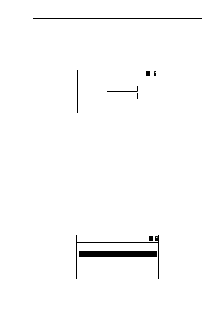
4.8 Retrieve points
In the software functions of this series total station, we need
to retrieve or input the coordinate data of points in many places,
but the method is same. Take the “Project->base” for example.
Pt.1:
Project->base
MEAS KNOWN
Pt.2:
ENT
A
● Retrieve the point of data files
1) Before retrieve the point, you must select a data file.
Specific operations see chapter “11.File manager”;
2) If you remember all points name, you can input the
name directly, then press [ENT],and the coordinate
data displayed as follows;
Pt.N:
Code:
Coord. data
N:
E:
Z:
146.325 m
265.364 m
1.256 m
56
road
3) If just remember a part of point name, you can find the
point by “*”.For example, input “5*”, you can find
24
some points whose name contains “5”, which are
displayed in the list(as shown below).Then, move the
cursor to the wanted point and press [ENT],and it will
display the coordinate of the wanted point and back to
the previous interface;
Pt.1:
Project->base
MEAS KNOWN
Pt.2:
ENT
A
Pt. list
12356
12357
▲
4) If the point input isn’t exit, you can enter the input
interface (as shown below).after the input, it save the
input data to the retrieved file, and then come back;
Input coord.
N:
E:
Z:
m
m
m
Pt.N:
Code: code
3
1
5) If you don’t input point name, then you will enter the
coordinate input interface (as shown below), and it
will not save the data, and come back directly;
●Retrieve known points
The operation of retrieving known point is same as it of retrieve
data files, but the differences are as below;
1) The data of coordinate point is retrieved in the known
files
2) Input the point name and press the key [ENT];
3) If the point doesn’t exit, it will tip you that “No data
match”, and it doesn’t support direct input.
4) The point name can’t be null.
25
4.9 Measured point
In the software functions of this series total station, we need
to retrieve or input the coordinates data of points in many places
as well as obtain the coordinate data by field measurements. The
method is as same as retrieving points. Take“Project->base” for
example.
Pt.1:
Project->base
MEAS KNOWN
Pt.2:
ENT
A
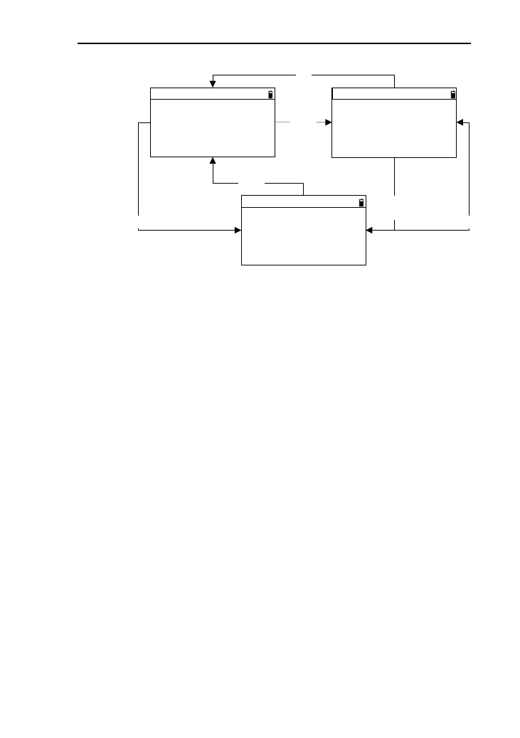
1) Press the key [MEAS], then enter into the interface (as
shown below;
Meas. target
HR:
Vz:
SD:
*[Hot] to set T.H
MSR1 MSR2
m
45º23'53"
89º52'36"
2) The angle displays real time, and press [MSR1] or
[MSR2] to start measuring;
3) After a distance measurement is ended and successful
(if repeat mode or track mode, you should press [ESC]
to end.), enter the interface of saving data automatically.
After saving successfully, it will come back to the point
input interface, and refresh to display the saved point.
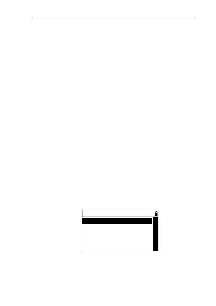
4.10 Retrieve code
On the interface with inputting code, you can input code by
retrieving.
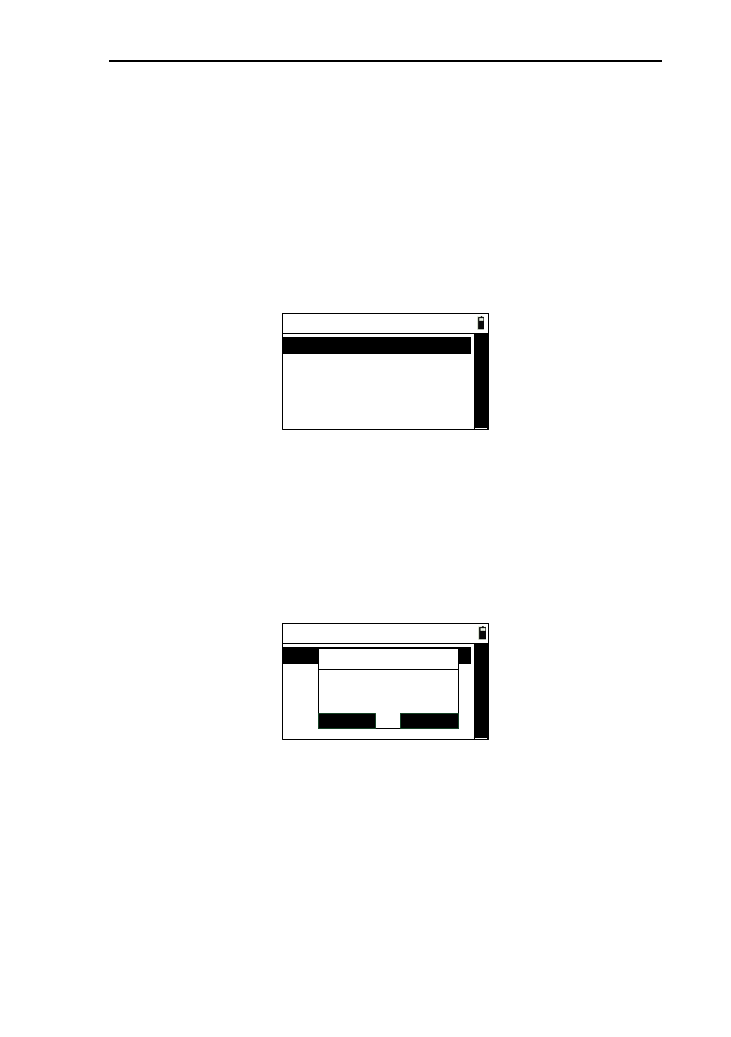
1) Press [LIST] to enter the code list (as shown below),
and press [◄] or [►] to move cursor;

26
Code manager 1/1
SRH. ADD
DEL. LAST
code1
code2
2) If the code data are multipage,you can move the cursor
to the last and move cursor again, then you can press
[▼] to next page, or you can press [◄] or [►] to next
page;
3) After select the code, press [ENT] to come back, and
the code will be refreshed.
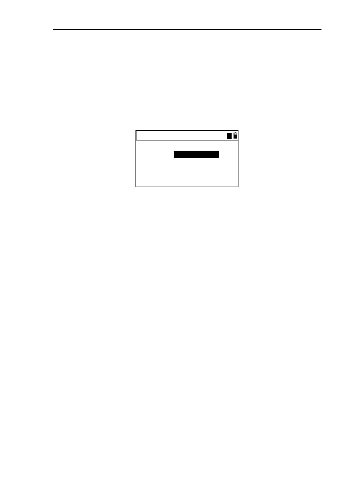
4.11 Record point data
4.11.1 Record data without displaying
1) Under the functions with saving data, press [REC.] to
enter the interface of recording data ,which will
displays the default “Pt .N”, “T.H”, “Code”, and the
cursor is at the place where input code;
2) If want to change “Pt .N”, “T.H”,you can move cursor
where you want to change by pressing [▲] and [▼];
3) When moving the cursor to “Code”, you can press
[LIST] to retrieve code;
4) When the cursor is at “Code”, you can press [ENT] to
save data. After the save is successful, it will tip you;
5) If the saved data are coordinate and the target height is
re-input, the value of Z-coordinate will be
re-calculated.
27
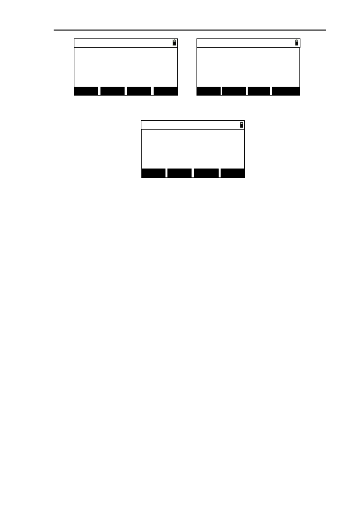
4.11.2 The display of saved data
HR:
Vz:
SD:
DSP REC. LIST DSP REC.
Z:
N:
E:
[DSP]
[DSP]
Pt.N:
Code: 1
code
Pt.N:
Code:
45º23'53"
89º52'36"
AA
1
code
42.365 m
146.325
265.364 m
1.256 m
1) Under the functions with saving data, press [REC.] and
enter the interface of recording data ,which will
displays the default “Pt.N”, “T.H”, “Code”, and the
cursor is at the place where input name;
2) When the cursor is at “Code”, you can press [LIST] to
retrieve code;
3) Pressing [DSP], the displayed data will be changed
between angle -distance and coordinate;
4) When the cursor is at “Code”, you can press [ENT] to
save data. After the save is successful, it will tip you.
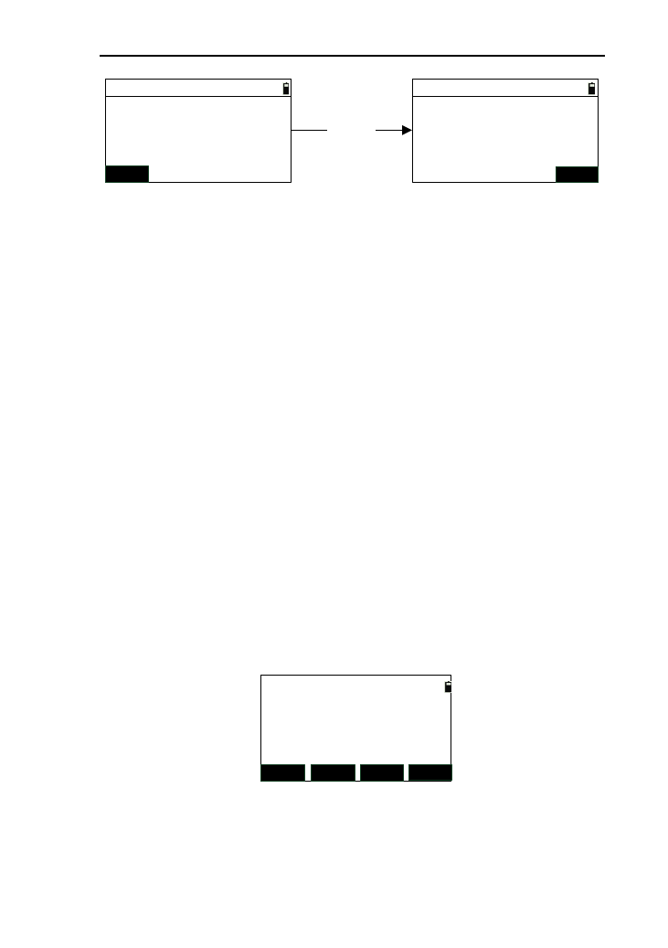
4.12 Basic measurement
You will enter the basic measurement after switch on the
instrument. There are three interfaces about basic measurement.
28
HR:
Vz:
SD:
Pt.N:
T.H:
Basic 1/3
Pt .N:
T.H:
Basic 3/3
Z:
N:
E:
HD:
VD:
Pt .N:
T.H:
Basic 2/3
[DSP]/
[▼]SD:
[DSP]/
[▼]
[DSP]/
[▼]
[▲]
[▲]
[▲]
45º23'53"
89º52'36"
1
1.680 m
Pt.N: It defaults to the point name which is the last point
name added 1before last shutdown;
T.H: it defaults to the value of target height saved by
system.
Under the basic measurement, the function which can be
completed, as follows:
Measurement
1) You can proceed with angle measurement, distance
measurement, and coordinate measurement;
2) The angle value will be refreshed in real time as
turning the instrument;
3) Press [MSR1] or [MSR2] to measure distance with the
settings of the measurement;
4) Introduction: the distance measurement mode will be
displayed when start to measure distance;
“*C”indicates constant measurement
“*S”indicates single measurement
“*R”indicates average measurement
“*T”indicates track measurement
5) Every successful measurement, the buzzer goes off and

29
the current measured data are displayed whatever
interface;
6) Pressing [DSP] or [▲] [▼] can view the measured
data.
Save data
1) When the measurement is set as “AUTO”,it will enter
the interface of saving data automatically after
measuring success, and save the coordinate data;
2) When the measurement is set as “ENT”,it will enter
the interface of saving data by pressing [ENT] and the
saved data is coordinate data;
3) If you press [ENT] directly without distance
measurement, it will also enter the interface of saving
data and the saved data is angle data.
Other functions
The entrance of the other functions of this series total station
is in the basic measurement interface.
1) Pressing[1]: Enter the function of “User keys 1”
defined, which defaults to file manager;
2) Pressing[2]: Enter the function of “User keys 2”
defined, which defaults to exporting and importing file;
3) Pressing [3]: Enter the “Input code” function;
4) Pressing [4]: Enter the “Program” menu;
5) Pressing [5]: Enter the “Cofig” menu;
6) Pressing [6]: Enter the “Data ” menu;
7) Pressing [7]: Enter the stationing menu;
8) Pressing [8]: Enter the “Stake out” menu;
9) Pressing [9]: Enter the “Offset” menu;
10) Pressing [0]: Enter the “Electronic bubble” interface;
11) Pressing [▪]: Enter the “Hotkey” menu;
12) Pressing [★]: Enter the “Shot cut” interface;

30
13) Pressing [ANG]:Enter the “Angle” menu.
31
5. Angle
If you want to use the functions about resetting
angles,precise measurement of the Angle in the process of using
the instrument, enter the angle menu for the correlation
operations of angle.
In the basic interface, you can press [F4] to enter the angle
menu, which is as follows:
----Angle----
1.Set 0
2.Set HA
3.Hold HA
4.HA repetition
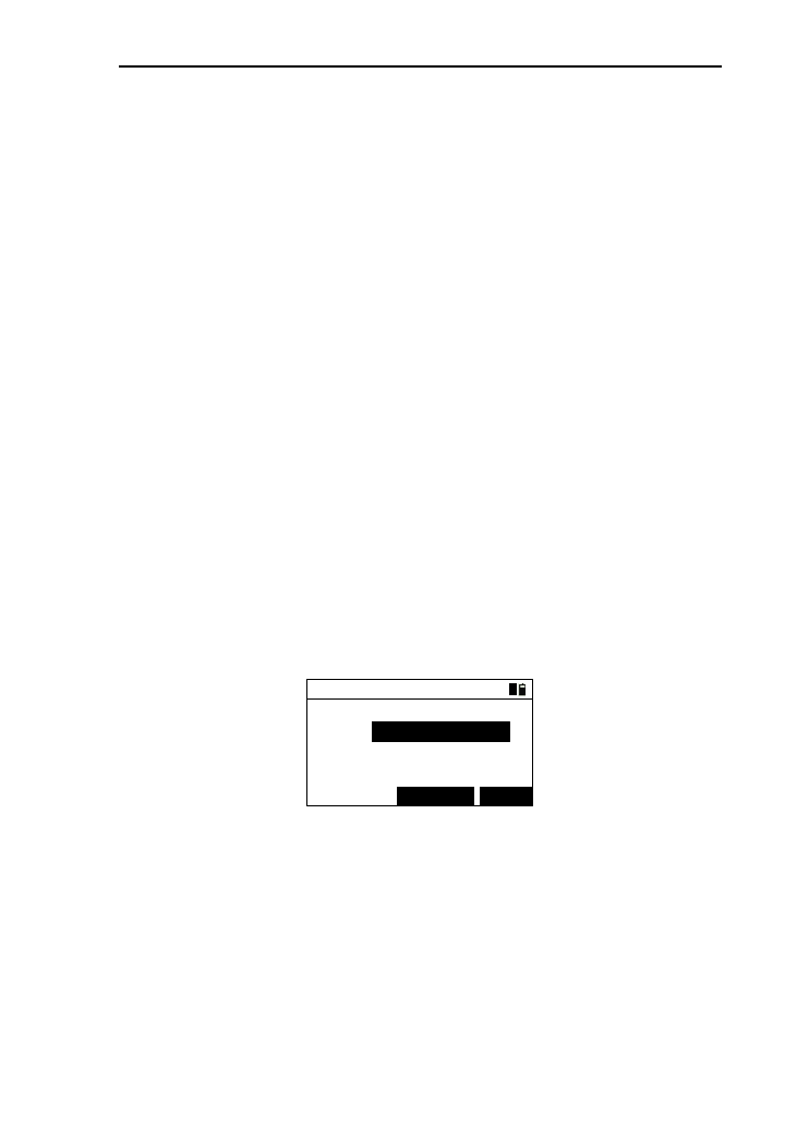
5.1 Set 0
If you want set the current horizontal angle as 0 degree, this
function will help you.
1) In the angle menu interface, select “1.Set 0”,then a
interface will be appeared as follows:
----Angle----
1.Set 0
2.Set HA
3.Hold HA
4.HA repetition
Info
ENT
ESC
Set HA to 0
Continue?
2) Press [ENT], then the interface comes back to the
basic measurement, and the horizontal angle is set as 0
degree with buzzer ringing if it is opened;
3) Press [ESC], then the interface comes back to the
angle menu interface;
32
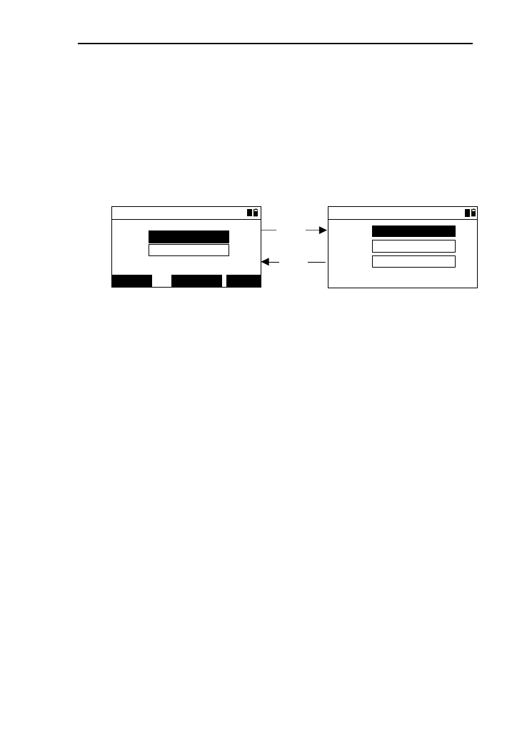
5.2 Set HA
If you want to set the horizontal angel what you want, this
function will help you.
1) In the angle menu interface, press [2] or press [ENT]
after moving the cursor to “2.Set HA”to enter the
“Input angle ->Set A” interface as shown below:
Input angle->SetA
HR:
1
*[ENT] to set A
2) Take the value of angle input to four decimal
places .the range is “0°~359°59′59″” under the “DMS”
mode of angle unit;
3) Input an angle in the input box, then press [ENT],the
interface comes back to the basic measurement with
the horizontal angle set as what you input;
4) Press [ESC] to return to the angle menu.
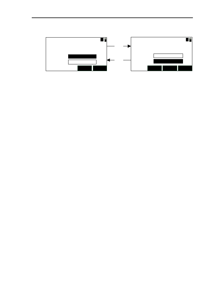
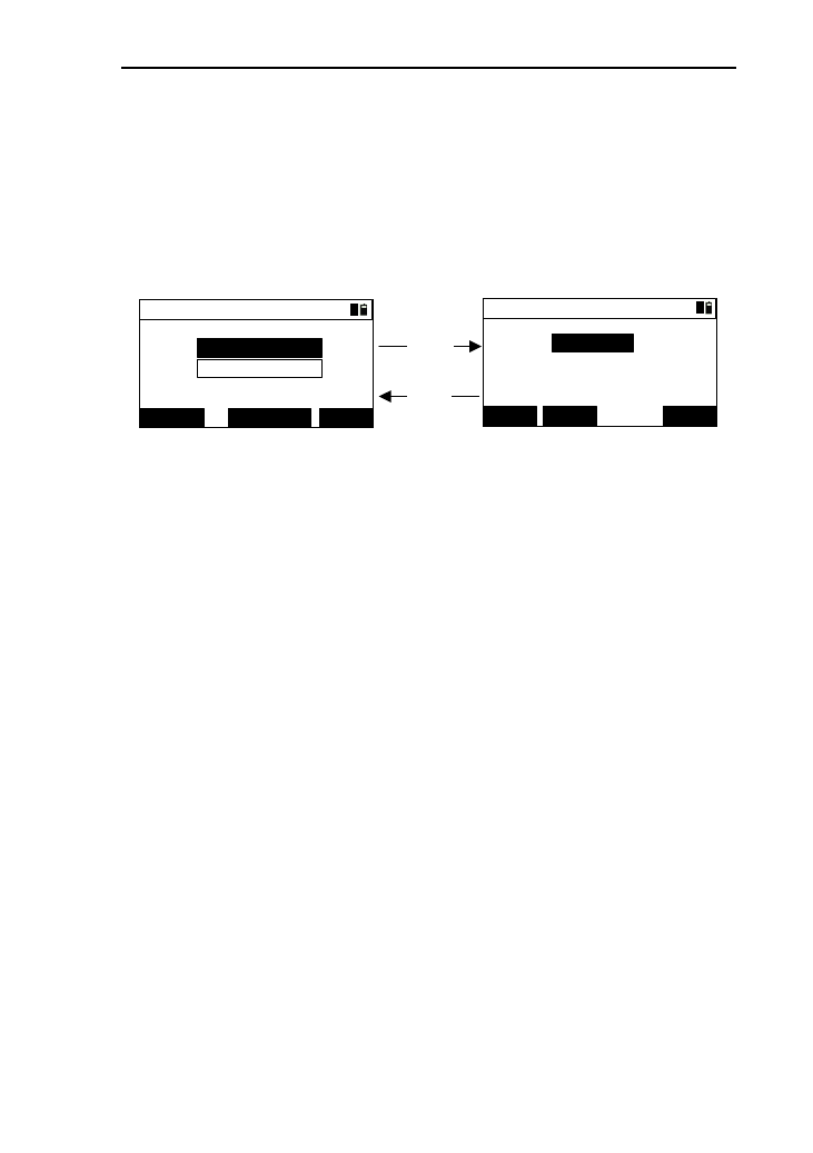
5.3 Hold HA
This function is that hold the current angle and turn the
instrument at right direction, then release the held angle. By this
way, the horizontal will be set as the angle held.
1) In the angle menu interface, you can press the [3] or
press the key [ENT] after moving the cursor to “3.Hold
HA” to select “Hold -> Set” function.
33
Hold->Set
HOLD
HR:
*Keep until release
(1)
Hold->Set
REL.
HR:
*Keep until release
[HOLD]
(2)
20°27′39″20°27′39″
2) Enter to the “Hold -> Set”(1),then turn the instrument
and the horizontal will be changed in real time. Then,
press [HOLD], the current value will be held with
unchanged and enter to the interface (2);
3) Turn the instrument at a right direction, then press
[REL.], the interface will come back to the basic
measurement with the current horizontal angle set as
the held angle;
4) Press [ESC] and the interface return to the angle menu.
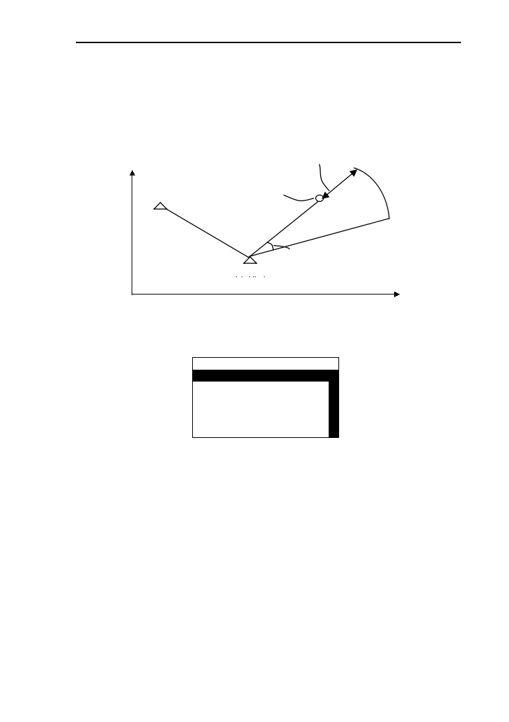
5.4 HA Repetition
This function is to obtain the angle between backsight point
and foresight point with repeated measurement, and can get the
coordinates of the foresight at the same time.
1) In the angle menu interface, press[4] or press [ENT]
after moving the cursor to “4.Angle repetition”to enter
the angle repetition interface ,which as follows:
MSR1 ANG
Avg:
Sum:
Angle:
MSR2
Read:
HD: *Aim FS.
ESC
0°00′00″
0°00′00″
0°00′00″
Cnt. 0 m
[Note*]:
“SUM”: The cumulative measured values of the horizontal
angle.

34
“AVG”: The cumulative average values of horizontal
angle.
“Angle”: The real-time angle value between the backsight
point and the foresight point after every repeated measurement.
“Read”: The number of completing angle repetition
“HD”: The horizontal distance value of the foresight point
measured.
2) According to the prompt “Aim BS.”, aim at backsight
point, and then press [ANG];
3) According to the prompt “Aim FS.”, turn the
instrument (the angle is changed in real time),and press
[ANG].After these operations, a angle measurement is
completed , and the values of “SUM”,“ AVG”, “Read”
will refreshed;
4) Repeat the operations of step “1)” and “2)”,but a
maximum of ten angle repetitions is allowed. If you
press [ESC],the operation of this angle repetition will
be canceled and return to the previous operation;
5) You can measure the distance of the foresight point
with the keys [MSR1] or [MSR2] after aim at the
foresight point and press [ANG]. If press [ENT] again,
you can record the measured data;
6) Press [ESC], and the interface will come back to angle
menu.
35
6. Setup Station
This function is to confirm the coordinates, north of the
station and the surveying Coordinate Systems.
In the basic measurement, press the key [7] to enter the
staking out menu, which as follows
----Setup Stn----
1.BS coord.
△
△
2.BS angle
3.Resection
4.Quick
5.Remote BM
----Setup Stn----
3.Resection
△
△
4.Qiuck
5.Remote BM
6.BS check
7.View STN
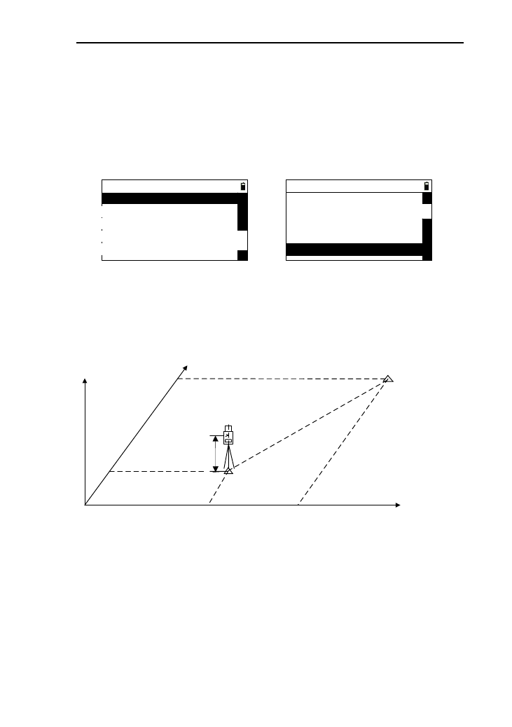
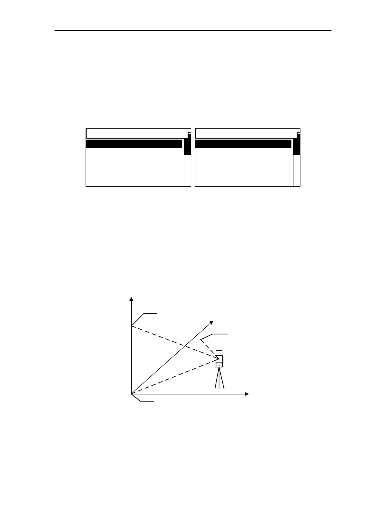
6.1 BS coord.
This function is to confirm the coordinate system according
to the known station and the coordinates of the backsight point.
Y
ZX Backsight
(Xb,Yb,Zb)
Station
(Xi,Yi,Zi)
Xb
X0
Y0 Yb
Target
Height
1) In the menu interface of stationing, select the options
“BS coord.”, then press the key [ENT] to enter the
“Input STN & BS” interface. See the picture as
bellow;
36
Input STN & BS
STN:
KNOWN
I.H:
BS:
T.H:
*Aim BS.
m
m
1
2) Retrieve the point (see the chapter 4.8),then the
display of “STN” will be refreshed, at the same
time ,the cursor moves to the input box of
“I.H”(instrument height);
[Note*]:Here, the “STN” can’t be null.
STN: Station name
I.H: Instrument height
T.H: Target height
3) Input the instrument height in the “I.H” input box;
4) Input the name of backsight point, as same as the
operation of “STN” input;
5) Input the target height in the “T.H’ input box, then aim
at backsight point, and press the key [ENT] to enter
the interface of “BS .check 1/2”. As shown below:
BS. check 2/2
DSP
MSR2
MSR1
Z:
m
m
m
E:
N:
BS. check 1/2
Cal HR:
HD:
dHD:
dHR: m
m
91º42′34"
0º00"00′
DSP
MSR2MSR1
[DSP]
[DSP]
6) Press the key [DSP] to switch the display page;
7) Press the key [MSR1] or [MSR2] to start distance
measurement, if the distance measurement is on,it will
be stopped.(Pressing the key [5] can modify the
parameters of measurement). After a successful
measurement, the measured data will be displayed and
you can check by turning pages;
37
8) If you want to save the measured data of checked
backsight, just press [ENT] and it will prompt you
“Save BS coord?”, if not,press the key [ESC] with a
prompt “Finished” and back to the basic interface.
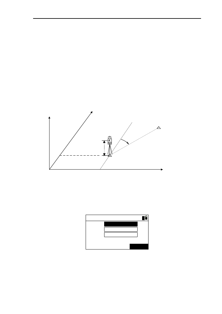
6.2 BS angle
This function is to determine the coordinate system and
according to the coordinate of station and the angle between
station and backsight point ,and set up station according to
instrument height.
Y
ZX
X0
Y0
Azimuth
Target
Height
Station
(Xi,Yi,Zi)
Backsight
(Xb,Yb,Zb)
1) In the menu of stationing, press the key [2] or select “2.BS
angle” to enter the interface of “BS angle”(as shown below).
If the station has been stationing, there will be default data
displayed;
BS angle
STN:
KNOWN
12345
I.H:
BSA:
*[ENT] after aim BS
m
0.3
180.0000
1
2) Retrieve the point (see the chapter 4.8), then the display of
“STN” will be refreshed, at the same time,the cursor moves
to the input box of “I.H”(instrument height);
[Note*]: Here, the “STN” can’t be null.
38
3) Input the name of backsight point, as same as the operation
of “STN” input;
4) Input backsight angle in the “BSA’ input box, then aim at
backsight point, and press the key [ENT] to return to the
interface of basic measurement.
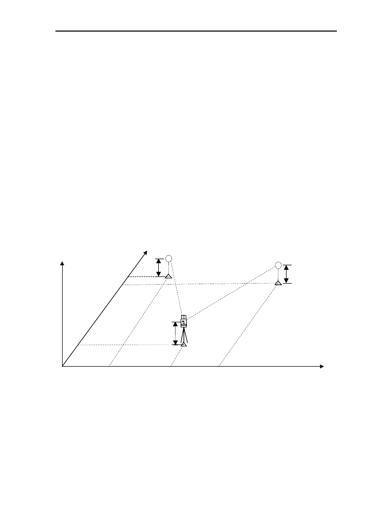
6.3 Resection
This function adopts two or more points (the maximum of 5
points) to set station by angle measurement or distance
measurement. You can measure distance and angle or just angle
with this function. If the measured values are enough, it will
calculate the coordinate automatically. But the condition of
calculation is that at least distance measurement for two points
or angle measurement of three points, or together.
Y
ZX
Station
(Xi,Yi,Zi)
X1
X0
Y0 Y2
Instrument
height
Known point 2
(X2,Y2,Z2)
Height 2
Height 1 Known point 1
(X1,Y1,Z1)
X2
Y1
The flow chart is as shown below
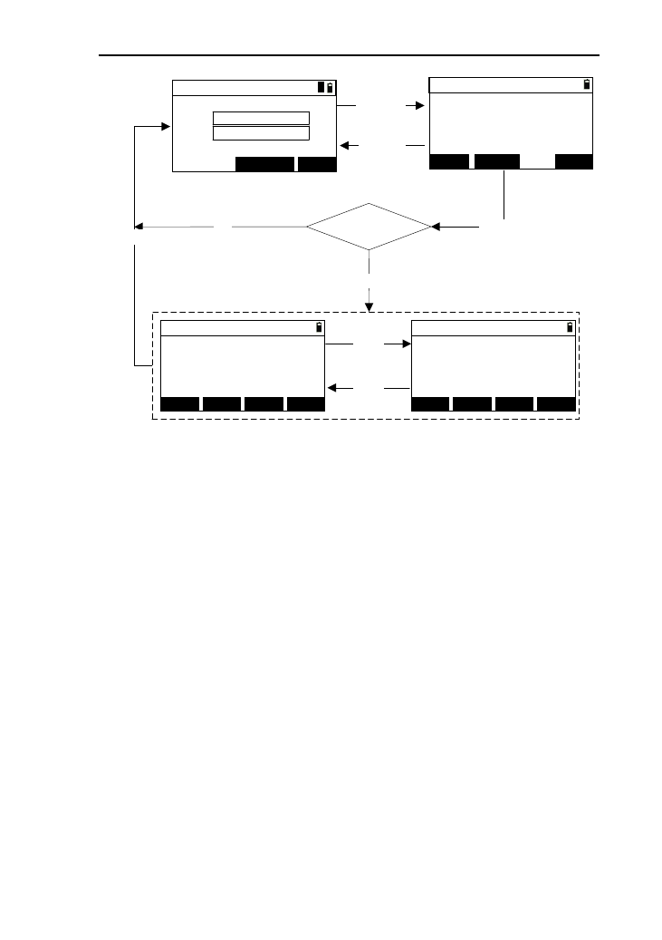
39
(1)
Calculate ?
Yes
NO
[ADD]
【ENT】
[ENT]
(2)
(3)
【ESC】
HR:
HD:
Res.->Meas.
SD: m
m
*Meas. or [ENT]
MSR1 QUIT
91º42′34"
0.526
0.528
MSR2
Pt.N:
T.H:
RES.->Input <1>
12345
0.300 m
KNOWN QUIT
Res. -> Result 1/2
Z:
m
m
m
E:
N:
*[REC] to save STN
1.123
2.234
3.345
ADD QUITDSPREC.
Res. -> Result 2/2
*[REC] to save STN
ADD QUITDSPREC.
dZ:
m
m
m
dE:
dN: 0.000
0.000
0.000
[DSP]
[DSP]
1
1) Under the menu of stationing, Press [3] or press [ENT] after
selecting “3.Recection” in the interface of “ Res.->Input”
, which as picture (1),then retrieve the point;
2) Retrieve the point (see the chapter 4.8), then the display of
“Pt .N” will be refreshed, at the same time, the cursor moves
to the input box of “I.H” (instrument height);
3) Input target height in the “I.T” in put box and press the key
[ENT] to enter to the interface of “Res.->Meas.”,as shown
above(2);
4) Aim at the target, press the key [MSR1] or [MSR2] to
measure distance and press [ENT] or press [ENT] to
measure angle directly without measuring distance , then
enter the next point input interface;
5) After completing distance measurement of two points or
angle distance, enter to the interface of “Res.->Result”,
40
which as shown picture (3);
6) Pressing [ADD] can add data;
7) Pressing [DSP] can switch the interfaces of data;
8) Pressing [REC.] or [ENT] to record data with a prompt
“Finished”, and come back to the interface of stationing
interface.
6.4 Quick
This function can station quickly without the coordinates of
station and backsight, which is equal to free-station.
1) Press the key [4] or select “4.Quick” and press [ENT] to
enter the interface of “Quick” interface,as shown below . If
the station has been set station, there will be the default data
displayed;
KNOWN
Quick
0.300
123
12345
STN:
I.H:
BS: m
AZ: 20.0000
1
2) Input a point name in the “STN” input box, or you can press
[ENT] or [KNOWN] to retrieve points. If the point name
doesn’t exist, the default coordinate of station is (0,0,0);
[Notice*]: The station name can’t be null.
3) Input the target point in the “I.H” input box, and then press
[ENT];
4) Input the azimuth in the “AZ” input box, and press [ENT]
with a prompt “Finished” and back to “Basic” interface.
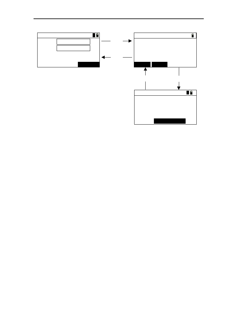
6.5 Remote BM
When the Z coordinate of station is changed, you can
upgrade the coordinate based on measured point.The flow chart
41
of remote elevation measurement is below:
[ENT]
【ENT】
(2)
(1)
(3)
[ESC]
【ESC】
MSR1 MSR2
KNOWN
RBM->Input
0.000
12345
Code:
m
7
Pt.:
T.H:
RBM->Meas.
HD: m
m
VD:
HR:
*[ENT] save after meas.
91º42′34"
0.145
0.560
RBM->Result
Z:
m
m
m
E:
N:
STN:
I.H: 0.300 m
-23564.203
-29546.256
-0.300
2
1
1
1) Press the key [5] or select “5.Remote BM” and press [ENT]
to enter the interface of “RBM->Input” interface,as shown
(1) below;
2) Retrieve the point (see the chapter 4.8), then the display of
“Pt .” will be refreshed, at the same time, the cursor moves
to the input box of “I.H” (instrument height);
3) Input target height in the “I.T” input box and press the key
[ENT] to enter to the interface of “RBM.->Meas.”, as
shown above;
4) Press [MSR1] or [MSR2] to start measurement. after a
successful measurement, the values of “HD” and “VD” are
displayed;
5) Press [ENT] to enter the interface of “RBM->Result” ,(as
shown (3) above) ;
6) Re-input the instrument height in the “I.H” interface;
7) Press [ENT] with a prompt “STN-Up-to -date” and come
back to the stationing menu.
42
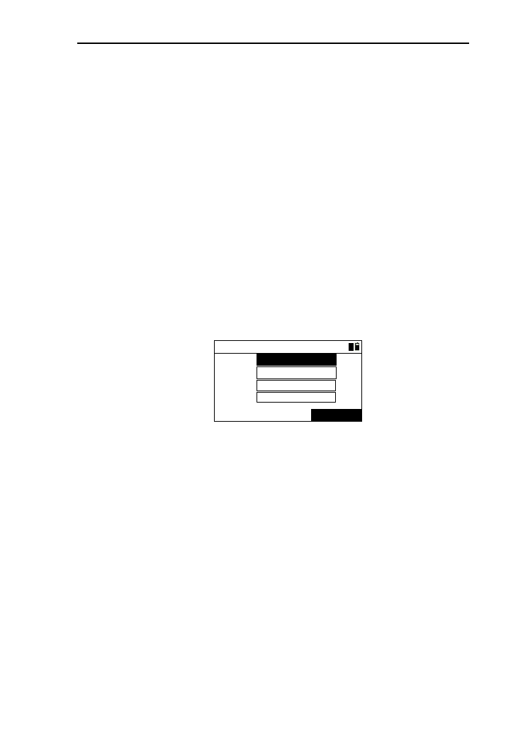
6.6 BS check
This function can be used to check the current horizontal
station and the backsight angle of last stationing, and also reset
backsight height.
1) Press [6] or select “BS check” and press [ENT] to enter
the interface of “BS check”.(as shown below);
ESC RESET
BS check
HA:
BSA:
* BSA reset
41º24′12"
91º42′34"
2) Press [ENT] to come back to stationing menu;
3) Press [ENT] or [RESET] to come back to
“Basic”;interface and reset the current angle as
backsight angle.
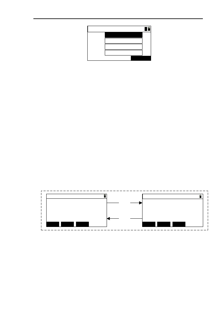
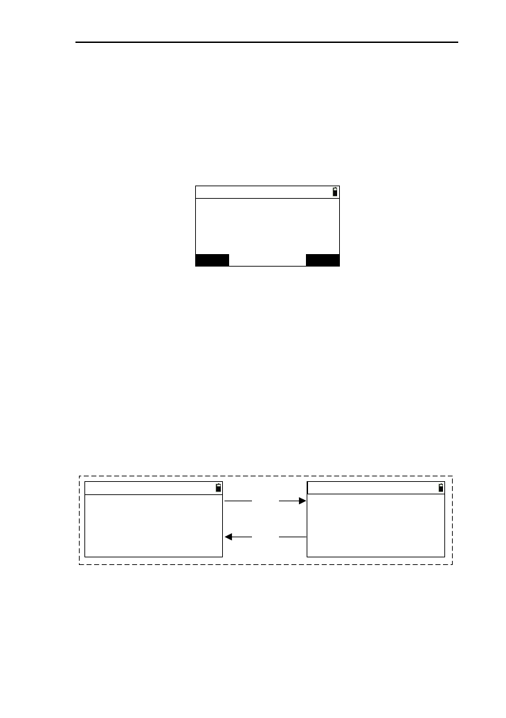
6.7 View STN
This function is to check the coordinates, angle, name of
backsight point, station name, instrument height and etc;
1) Press [7] or press [ENT] after select “7.View STN” to
enter the interface of “BS check”.(As shown below)
STN info 1/2
STN:
STN 2/2
I.H:
Z:
m
m
m
E:
N: -23564.203
-29546.256
-0.300 Z:
m
m
m
E:
N: -23564.203
-29546.256
-0.300
BS:
BSA:
2
0.300 41º24′12"
m
[DSP]
[DSP] 3
2) Press [DSP] to switch displays. One of interface of
“STN info 1/2” displays the station data, and the other
interface of “STN info 1/2” is the data of backsight;
3) Press the key [ENT] or [ESC] to return to the stationing
menu.
43
7. Stake out
Staking out is to find the earth point for the designing point,
which also means setting out.
Backsight Len
Distance
difference
Station Angle difference
Setting out point
In the basic interface, press the key [8] to enter the menu of
staking out, which as shown below.
----Stake out----
1.S-O ang.&dist.
△
△
2.S-O coord.
3.S-O equidist.
4.S-O line pt.
5.S-O line
7.1 S-O ang.&dist.
This function is to stake out according to the calculation of
the inputs of horizontal distance, height difference, horizontal
distance between stakeout point and station.
1) In the menu of staking out, you can press the key [1] or
press [ENT] after selecting “S-O ang.&dist.”to enter
the interface “S-O polar-> Input”, which as shown
below;
2) Input the horizontal distance in the “HD” input box,
and then press [ENT] or [▼];
44
3) Input the height difference in the “HV” input box, and
then press [ENT] or [▼];
4) Input horizontal angle in the “HA” input box;
[Notice*]:
“HD”: the horizontal distance between stakeout point
and station.
“HV”: the height difference between stakeout point
and station.
“HA”: the horizontal angle between stakeout point
and station.
5) Press [ENT] to enter the interface of “SO -> Result
1/3”,please refer to the operation of chapter “7.6”.
7.2 S-O coord.
This function is to stake out according to the coordinates of
staking out point.
1) In the menu of staking out, you can press the key [2] or
press [ENT] after select “S-O coord.” to enter the
interface “S-O coord.-> Input”, which as shown below;
S-O Coord.-> Input
Pt.N:
S-OKNOWN
1
2) Retrieve the point by reference to the operation of
chapter 4.8,and then the display of “Pt.N” will be
refreshed;
3) Press the key [S-O] to enter the interface of “S-O ->
Result” and see the operation of chapter 7.6.
45
7.3 S-O equidist.
Equidistance stakeout is to stake out the quarters which the
distance between the baseline points is divided.
Press the key [3] or press [ENT] after selecting “S-O
equidist” and to enter the interface of “Equidist.->base” ,which
as shown below:
(1)
[ENT]
[ESC]
MEAS ENTKNOWN
Equidist.->base
Pt.1:
Pt.2:
+ ENT-
Input pile No.
2
Stakes:
Pile: 1
11
(2)
1) Retrieve the point 1 by the reference to the operation
of chapter 4.8;
2) Pressing [MEAS] can perform the field measurement
of baseline points. See the chapter 4.9;
3) The way of the operation of point 2 is the same as it of
point 1.After finish retrieving, press [ENT] to enter the
interface of “Input pile No.”,which as shown in the
picture (2) ;
4) The default number of “Stakes” is 2, and the “Pile ” is
1. You can input the total number of stakes in the
“Stakes” input box. Because the stake contains the two
baseline points, the minimum number is 2;
5) Pressing [+] or [-] can increase or decrease the number
of stakes .The maximum value is two times of stakes
number;
6) Press [ENT] to enter the interface of “S-O
->Result ”.See the chapter 7.6.
46
7.4 S-O line pt.
This function is to stake out after calculate the data of
length, offset, height difference between stakeout point and
baseline point.
Press the key [4] or select the option “S-O line pt.” and
press the key [ENT] to enter the interface of “S-O line pt
->base”, as shown in picture (1).
[ENT]
[ESC]
(1)
MEAS ENTKNOWN
S-O line pt ->base
Pt.1:
Pt.2:
1
(2)
Input
m
Offset:
Length:
HV:
m
1
m
1) After retrieve point 1 by reference to chapter 4.8 ,
refresh the display of “Pt.1” at the same time move the
cursor to “Pt.2” input box.
2) Pressing [MEAS] can perform the field measurement
of baseline points. See the chapter 4.9;
3) The way of the operation of point 2 is the same as it of
point 1.After finish retrieving, press [ENT] to enter the
interface of “Input”, which as shown in the picture
(2) ;
4) Input the length value in the “Length” input box;
5) Input the offset value in the “Offset” input box;
6) Input the height difference value in the “HV” input
box and enter the interface of “S-O-> Result”and see
the operation of chapter 7.6.
[Notice *]:
Length: the horizontal distance between baseline point
and target point .The value of length along point
1 to point 2 is positive, otherwise, negative.
47
Offset: the Horizontal distance between target point and
its projective point on the baseline. The value of
offset along point 1 to point 2 is positive,
otherwise, negative.
HV: the height difference between point 1 and height
difference.
7.5 S-O line
This function is to stake out a straight line which parallels
to baseline after calculating the offset from staking out point to
baseline.
Press the key [5] or select the option “S-O line” and press
the key [ENT] to enter the interface of “S-O line->base”, as
shown in picture (1).
[ENT]
[ESC]
m
(1)
MEAS ENTKNOWN
S-O line->base
Pt.1:
Pt.2:
1Input
Offset:
1
(2)
m
1) After retrieve point 1 by reference to chapter 4.8 ,
refresh the display of “Pt.1” at the same time move the
cursor to “Pt.2” input box;
2) Pressing [MEAS] can perform the field measurement
of baseline points. See the chapter 4.9;
3) The way of the operation of point 2 is the same as it of
point 1.After finish retrieving, press [ENT] to enter the
interface of “Input”, which as shown in the picture (2);
4) Input the offset value in the “Offset” input box,and
press [ENT] to enter the interface of “S-O Line ->
Result”;
48
[Notice*]: Offset:the horizontal distance from the target
point to its projective point on baseline.
[DSP]
[DSP]
MSR1 QUIT
DSP
MSR2
S-O Line->Result 2/2
m
m
m
E:
N:
Z:
MSR1 QUIT
DSP
MSR2
S-O Line->Result 1/2
m
m
m
*Meas. target
Offset:
HV:
Length: *Meas. target
5) Aim at the target and press [MSR1] or [MSR2] to
measure .After a successful measurement, the
measured data will be displayed, and the coordinate is
of measured point;
6) Press [DSP] to switch the two pages of the result;
7) Press [QUIT], then return to staking out menu;
8) Press [ENT] to save the measured result.
7.6 The result measurement of the staking out
above.
The interface of “S-O->Result” is as below:
MSR1 DSP
MSR2 MSR1 DSP
MSR2
MSR1 NEXTP
DSP
MSR2
S-O -> Result 1/3
m
R←:
dHR→:
B↓:
m
U↑:
0° 00' 00"
m
S-O -> Result 2/3
VZ:
HR:
SD:
m
HD:
91° 25' 00"
m
90° 25' 43"
S-O -> Result 3/3
m
m
m
m
(1) (2)
(3)
[DSP]
[DSP]
[DSP] E:
N:
Z:
VD:
NEXTP
NEXTP

49
Turn the instrument until the “dHR” close to “0°00′00″”,and
you can conduct somebody to put the prism in the view of
telescope until close to the direction of measurement.
1) Aim at the target and press the key [MSR1] or [MSR2]
to measure the target .when the measurement is
completed, the difference value between target point
and staking out point is displayed on the first page.
dHR: the difference value form horizontal angle to
target point;
R/L:Lateral error
F/B: Longitudinal error
U/D:Dig/Fill
2) Press the key [DSP] to switch to the result display of
third page;
3) When the stakeout mode is “S-O ang&dist”, the key 4
will be the key [QUIT], which as shown in picture (1),
and you can press it to return back to the menu of
staking out;
4) When the stakeout mode is “S-O coord.”, the key 4
will be the key [NEXTP],which is for retrieving the
next point of the former point. As shown the picture
(2);
5) When the stakeout mode is “S-O equidist.”, the key 4
will be the key [QUIT],as shown picture (3) . Press
[QUIT] and return to the stakeout menu.
50
MSR1 QUIT
DSP
MSR2
S-O->Result 1/3
m
R←:
B↓:
m
U↑:
0° 00' 00"
m
S-O->Result 1/3
m
R←:
dHR→:
B↓:
m
U↑:
0° 00' 00"
m
MSR1 NEXTPDSP
MSR2
MSR1 QUIT
DSP
MSR2
S-O->Result 1/3 <1/2>
m
R←:
dHR→:
B↓:
m
U↑:
0° 00' 00"
m
(1) (2)
(3)
dHR→:
6) When the stakeout mode is “S-O ang.&dist.”, press
[ENT] to save the stakeout point and the point name is
the last recorded name adding 1;
7) When the stakeout mode is “S-O coord.”, press [ENT]
to save the stakeout point and the point name is the last
recorded name adding the value of setting of “S-O
Pt.N”.
51
8. Program
In the program measurement, there are many functions of
application measurements.
In the basic interface, press the key [4] to enter the menu of
program.
----Program----
1.Piont Proj.
3.MLM(AB-AC)
2.ARC
4.MLM(AB-BC)
5.REM
----Program----
5.REM
7.Bevel
6.Vert. Plane
8.Area & Girth
9.Road
8.1 Projection
This function is used to measure the length (X) of the prism
point deviation from the starting point of baseline, distance(Y)
of the prism point deviation from baseline, and altitude
difference (Z) of the prism point deviation from the starting
point of baseline.
X
Y
Station
Unknown point
Z
Measured point
Prism B
Prism A
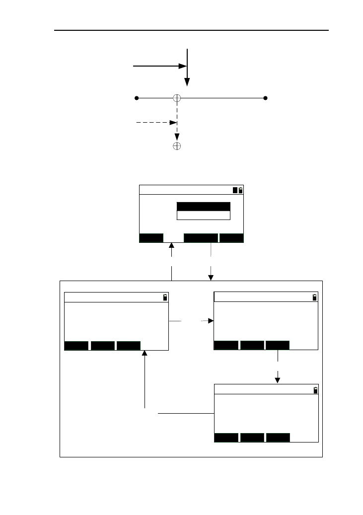
52
X
Y
Start point A End point B
Projective point
Measured point
Length Offset
Baseline
The flow chart of this function is as below:
Pt.1:
Project ->base
MEAS KNOWN
Pt.2:
Project-> Result1/3
MSR1 DSPMSR2
Length:
Offset:
HV:
*[ENT] record
Project-> Result 2/3
MSR1 DSP
MSR2
N:
E:
Z: *[HOT] to set T.H
Project-> Result 3/3
MSR1 DSPMSR2
[DSP]
[DSP]
[DSP] Vz:
HR:
SD:
*[ENT] record
(2)
ENT
[ENT][ESC]
(1)
1
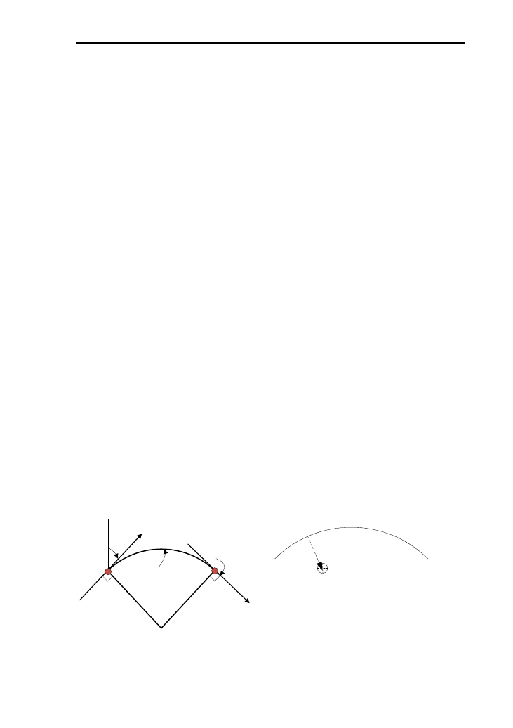
53
1) Press the key [1] or press [ENT] after move the cursor
to “Point Proj. ” to enter the interface of “Project
->base”;
2) After measuring or retrieve the coordinates of the two
points of baseline, press [ENT] to enter the interface of
“project -> Result ”;
3) In the interface of “Project ->Result”, press [MSR1] or
[MSR2] to start measuring after aim at measured point.
After a successful measurement, measured data will be
displayed;
4) Press the key [DSP] to check the measured data on
three pages;
5) Press [ENT] to enter the interface of “Rec. data”, you
can record the measured data;
6) Press [ESC] to return to the interface of
“project->base”.
8.2 ARC measurement
This function is used to measure the length (X) of the prism
point deviation from the starting point of arc, distance(Y) of the
prism point deviation from baseline of arc, and altitude
difference (Z) of the prism point deviation from the starting
point of baseline.
P1 P2
AZ1
radius
Arc
length
AZ2
O
●●
P1 P2
Measured pint
Offeset
Length
Sketch of arc
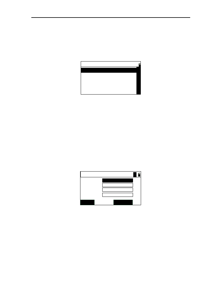
54
8.2.1 Define of arc
You should define the arc first when want to use this
function. In the menu of program, press [2] or press [ENT] after
moving the cursor to “ARC Meas.”, as shown below:
----ARC Meas.----
1.2Pt. and AZ
3.R and ARC len
2.R and AZ
The arc formed by data has most of the arc and less than
half arc. The ruler is that the arc we define, which is form start
point to end point and the direction is clockwise.
8.2.1.1 Define arc with two endpoints and azimuth
This function is to define arc by two endpoints and azimuth.
1) Press the key [1] or press [ENT] after moving the
cursor to “2Pt.and AZ” to enter the interface of
“ARC->2Pt.and AZ” ,as shown in picture below:
Pt.1:
ARC->2Pt.and AZ
MEAS KNOWN
Pt.2:
AZ.1:
AZ.2:
A
2) Retrieve or press [MEAS] to measuring the “Pt.1” or
“Pt.2”;
3) Input the two angle of contingence “AZ.1” and
“AZ.2”,then press [ENT] to enter the interface of
“ARC->Data” and display the arc data ,see the chapter
8.2.2;
4) Press [ESC] to return to the arc measurement menu.
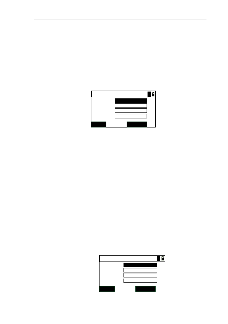
55
8.2.1.2 Define arc by radius and azimuth
This function is to define arc by using a start point,
radius and the azimuths of tangent of the two
endpoints.
1) Press [2] or [ENT] after moving the cursor to “R
and AZ” to enter the interface of “ARC->R and
AZ”, which as shown below:
ARC->R and AZ
MEAS KNOWN
Radius:
Pt.1:
AZ.1:
AZ.2: m
A
2) Retrieve or press [MEAS] to measuring the “Pt.1”;
3) Input the two angle of contingence “AZ.1”
“Radius” and “AZ.2”,then press [ENT] to enter the
interface of “ARC->Data” and display the arc
data ,see the chapter 8.2.2;
4) Press [ESC] to return to the arc measurement
menu.
8.2.1.3 Define arc with radius and arc length
This function is to define arc by using a start point of arc,
radius of arc, azimuths of tangent of start point and arc length.
1) Press [3] or [ENT] after moving the cursor to “R and
ARC len” to enter the interface of “ARC->R and len”,
which as shown below;
ARC->R and len
MEAS KNOWN
Radius:
Pt.1:
AZ.1:
Arc.L: m
m
A
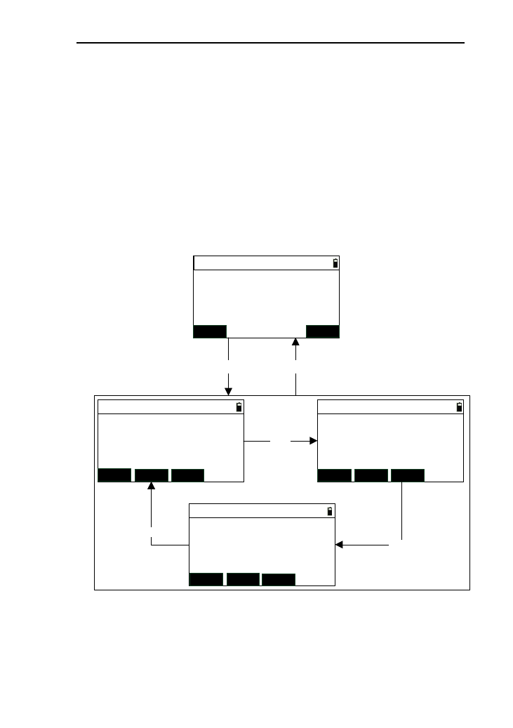
56
2) Retrieve or press [MEAS] to measuring the “Pt.1”;
3) Input the two angle of contingence “AZ.1” “Radius”
and “ArcL.”,then press [ENT] to enter the interface of
“ARC->Data” and display the arc data ,see the chapter
8.2.2;
4) Press [ESC] to return to the arc measurement menu.
8.2.2 Arc measurement
Enter the interface of “ARC->Data” after defining the arc,
as shown below:
ARC->Result 1/3
MSR1 DSP
MSR2
Length:
Offset:
HV:
*[ENT] record
ARC->Result 2/3
MSR1 DSPMSR2
N:
E:
Z:
*[HOT] to set T.H
ARC->Result 3/3
MSR1 DSP
MSR2
VZ:
HR:
SD:
*[ENT] record
[DSP]
[DSP]
[DSP]
(2)
ARC->Data
ESC ENT
Radius:
ArcL.:
AZ.2:
197.3431 m
301.9028 m
7°56′32″
(1)
[ENT] [ESC]
1) In the interface of “ARC->Data”,press [ENT] to enter
the interface of “ARC->Result ”,as shown in picture
(2);
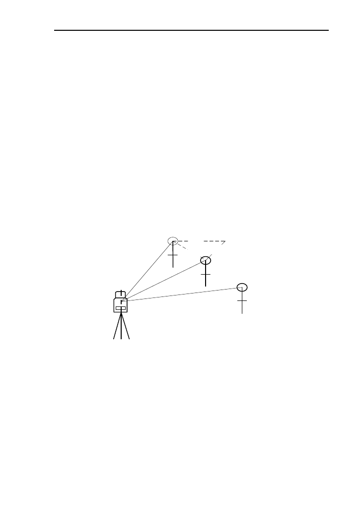
57
2) Aim at the prism point, and press [MSR1] or [MSR2]
to start measuring. After a successful measurement,
measured data will be displayed;
3) Press [DSP] to switch to check the data of the three
result pages;
4) Press [ENT] to enter the interface of “Rec. data”, and
you can record the measured data.
8.3 MLM
This function is to Measure the horizontal distance (dHD),
slope distance (dSD), elevation difference (dVD) and azimuth
angle (dHD) between two target. You may also input the
coordinate or retrieve coordinate from files to calculate value.
dHD
dVD
dSD Prism B
Prism A
Prism C
Instrument
There are two modes of MLM:
●.MLM (A-B,A-C): measure A-B, A-C, A-D…. i.e the
starting point is the reference point of all following points.
●.MLM (A-B, B-C): measure A-B, B-C, C-D…. i.e the
previous point is the reference point of all the other points.
8.3.1 MLM (A-B,A-C)
1) In the menu of program, press [3] or [ENT] after
moving the cursor to the interface of “MLM
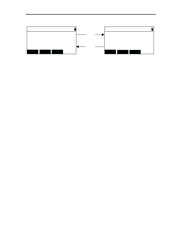
58
(AB-AC)”;
MLM->AB-AC 1/2
MSR1 DSPMSR2
rSD:
rVD:
rHD:
MLM->AB-AC 2/2
MSR1 DSPMSR2
rAZ:
rV%:
rGD:
[DSP]
[DSP]
m
m
m
2) Aim at the start point A, then press [MSR1] and
[MSR2] to start point. After a successful measurement,
the measured data from A to station will be displayed;
3) Measure point “B”, “C”, “D”, ……,in order, then the
data of “A-B” will be displayed ;
4) Press [DSP] to switch to check the measured data of
two pages;
5) Pressing [▪] can change the target height;
6) Press [ESC] to exit this function, and return to the
program menu.
8.3.2 MLM (A-B,B-C)
The interface of this function is as below:
The operation of this function is same as it of the chapter
8.3.1 “MLM (AB-AC)”.
8.4 REM (Remote height)
REM is adequate for measuring the height of target when
the prism cannot be placed at the target point. Under ‘REM’
mode, you can place the prism on any point along the plummet
line of the target point to obtain the height of target.
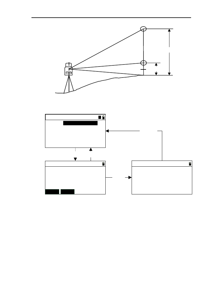
59
VD
Prism height
prism
P
Target point
C
1) Press the key [5] or [ENT] after move the cursor to
“REM”, which as in picture (1);
REM
T.H:
Elv.:
*Input T.H
1.034
REM
T.H:
Elv.:
*Aim and meas.
MSR1 MSR2
【ENT】【ESC】
REM
T.H:
Elv.:
*[ENT] to update HT
[MSR]
m
m
m
mm
m
【ESC】
1.034 1.034
1.034
(1)
(3)(2)
1
2) Input target height (the height difference from prism P
to target point C)in the “T.H” input box, and then press
[ENT] to enter the interface as shown in picture (2);
3) Aim at prism Pand press [MSR1] or [MSR2] to start
measuring. After a successful measurement, enter the
interface as shown in picture (3);
4) Turn the telescope to aim at measured point, at the
same time the height value will be refreshed in real
time until the height value of target height;
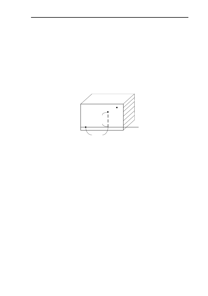
60
5) If you want to refresh the target height, press the key
[ENT];
6) Repeat step (3) to continue measuring;
7) Press the key [ESC] to return to the program menu.
8.5 Vertical plane measurement
This function is used to measure the offset and height
difference from any point of vertical plane to the start point of
the vertical plan baseline and coordinates of this point.
Point 1
Point 2
Aiming
point
Length
Vertical
interval
Baseline
1) In the program menu,press the key [6] directly or [ENT]
after move the cursor to “Vert. plane” ,and enter the
interface of “Vert. Plane ->Input”,as shown in picture
(1) below:
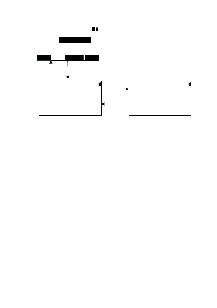
61
Pt.1:
Vert. Plane->Input
MEAS KNOWN
(1)
Pt.2: POINT1
POINT2
ENT
A
Z:
Vert. Plane->Result1/2
Length:
VD:
HR:
* [ENT] record
VZ:
Vert. Plane->Result 2/2
N:
E:
Z:
* [ENT] record
[DSP]
(page-1)(page-2)
[DSP]
(2)
[ENT][ESC]
m
m
mm
m
125.607
99.872
97°55′16″
56°13′44″
123.226
16.786
213.442
2) Input the two points for defining the vertical plane, and
after retrieving or measuring the coordinates of the two
points, press [ENT] to enter the interface of “Vert.
Plane->Result”;
3) Turn the instrument to aim at measured point in the
interface of “Vert. Plane->Result”,and the measured
data about “Length”, “VD” and coordinates will be
calculated automatically;
4) Pressing the key [DSP] to switch to check the result
data on the two pages;
5) Press [ENT] to enter the interface of “Rec. data”, and
you can record the measured data;
6) Press [ESC] to return to the interface of “Vert. Plane
->Input”.
8.6 Bevel
This function is used to measure the offset and vertical
interval from any point of slop plane to the start point P1 of the
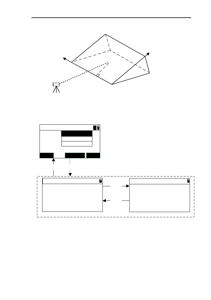
62
vertical plan baseline and coordinates of this point.
◆
◆
◆
{
◆
P3(X3,Y3,Z3)
P1(X1,Y1,Z1)
P2
(X2,Y2,Z2)
{
Length
Vertical
interval
Station
Target
(X,Y,Z)
1) Press the key [7] directly or press [ENT] after moving the
cursor to “Bevel->Input pt.,as shown in picture (1)”;
Pt.1:
Bevel->Input pt.
MEAS KNOWN
(1)
Pt.3:
POINT1
POINT3
ENT
A
Z:
Bevel ->Result 1/2
Length:
VD:
HR:
*[ENT] record
VZ:
Bevel ->Result 2/2
N:
E:
Z:
*[ENT] record
[DSP]
(page-1)(page-2)
[DSP]
(2)
[ENT][ESC]
m
m
mm
m
12.104
49.634
31°15′56″
68°13′34″
43.246
76.996
215.402
Pt.2: POINT2
2) Input three points for defining the slop plane. After
retrieving or measuring the coordinates of these three points,
press [ENT] to enter the enter the interface of the
“Bevel->result” ;
3) Turn the instrument to aim at the measured point, then the
data about the offset,vertical interval and coordinates will be
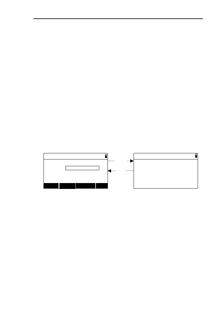
63
calculated in the interface of “Bevel->Result”;
4) Pressing the key [DSP] to switch to check the result data on
the two pages;
5) Press [ENT] to enter the interface of “Rec. data”, you can
record the measured data;
6) Press [ESC] to return to the interface of “Bevel ->Input”.
8.7 Area & Girth
This function is used to calculate the area and perimeter of
the plane figure which is enclosed by the measured or input
points.
1) In the program menu ,press the key [8] or [ENT] after
moving the cursor to “Area & Girth”, then enter the
interface of “Area&Per.->Input”,as shown in figure
(1);
Pt.N:
Area and Per.->Input
MEAS KNOWN
(1)
CALC
Area and Per.->Result
Area:
Girth:
*[ESC] back,[ENT] record
[CALC]
[ESC]
QUIT
*Input no 1pt.
(2)
10.000
23.508
sqm
m
2) Input the point name and retrieve or measuring the
point n. When you complete the input of one point, it
will enter the next point input automatically;
3) When the number of point input is three or more than
three, press [CALC] to enter the interface shown in
picture (2),the calculation of the area and perimeter will
be displayed;
4) Press [ENT] to record the data of area and perimeter,
then return back to the program menu;
5) In the interface (2),press the key [ESC],and return back
to the interface of “Area&Per.->Input”;

64
6) In the interface (1), press [ESC] to return to the
previous point;
7) In the interface (2), press [QUIT] to return to the
program menu.
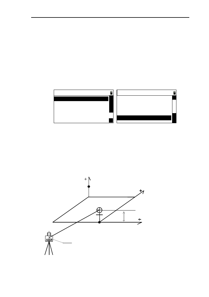
65
9. Offset
These functions are help for coordinate measurement and
can get the coordinates of points which the prism can’t be access
to.
You should prepare to station, orientate, and input
instrument height firstly. In the basic interface, press [9] to enter
the menu of offset as shown below:
----Offset----
1.Offset/Dist
3.Offset/2D
2.Offset /Angle
4.Offset/HD
5.Offset/Column
△
△
----Offset----
6.Offset/SD
3.Offset/2D
2.Offset /Angle
4.Offset/HD
5.Offset/Column
△
△
△
9.1 Single-Distance Offset Mode
If have already known the front &behind and left & right
offset along the direction of observation which from measured
target point to measured point, you may measure the coordinate
of target point A0 through distance offset.
Instrument Center
Target
height
Measured point
Target height
left & right
front &behind
up &down
1) In the offset menu, press the key [1] or press
[ENT]move the cursor to “Offset /Dist” to enter the
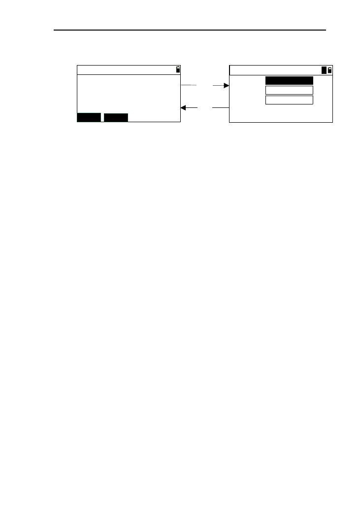
66
interface of “Offset/Dist ->Meas Pt”,as shown in
picture (1);
L/R:
F/B:
U/D:
*R/F/U:+
(2)
Offset/Dist->Input
HR:
VZ:
SD:
*[HOT] to set T.H
Offset/Dist->Meas Pt
MSR1 MSR2
[MSR]
[ESC]
m
m
m
*L/B/D:-
m
35°34′17″
69°42′11″
213.983
(1)
1
2) If you want to change the target height, press the key
[▪];
3) Aim at the measured point and press [MSR1] or
[MSR2] to start measuring. After a successful
measurement, ether the interface, as shown in picture
(2);
4) In the interface as shown in picture (2), you can press
the key [ESC] back the interface as shown in picture
(1);
5) In the interface as shown in picture (2), input the value
of the offset which the target point deviates from
measured point. In the “U/D” input box, press [ENT]
to enter the interface of saving point, and this interface
displays the data of angle, distance and coordinate;
[Notice *]
*R/F/U: Right/front/up and these input values are
positive
*L/B/D: Left/behind/down and these input values are
negative
6) Input the coordinates of the point and press
[ENT] .After saved the data, return back to the offset
menu;
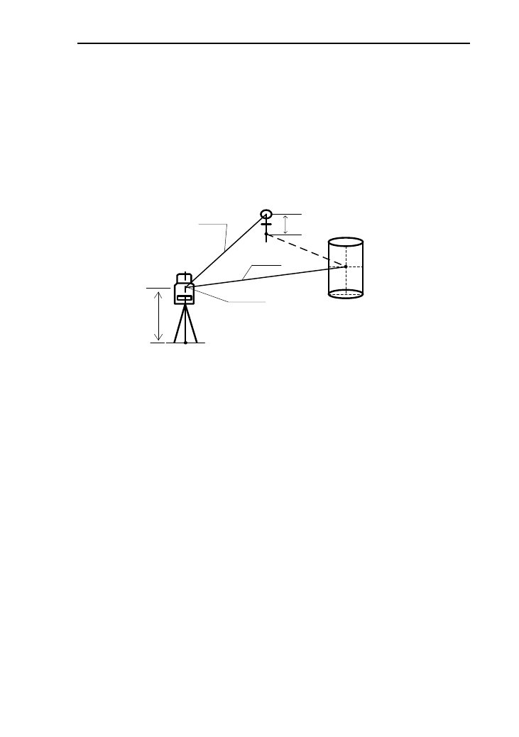
67
9.2 Angle offset Mode
This mode is specifically useful when setting up prism
difficulty. The mode is specifically useful when setting up prism
difficultly, e.g. in the center of a tree. Set up the prism at the
point ‘P’ which is the same horizontal distance away from the
instrument .The diagram for angle offset is as followed.
Instrument center
Station
Prism P
HD(f)
HD(r)
HD(r)=HD(f)
Offset point
Measured point
Target height
Instrument height
HD(f):The horizontal distance between offset
point between instrument center
HD(r):The horizontal distance between measured point
and instrument center
1) In the offset menu ,pres [2] or press [ENT] after
moving the cursor to enter the interface of
“Offset/Angle->Meas P, as showing in picture (1):
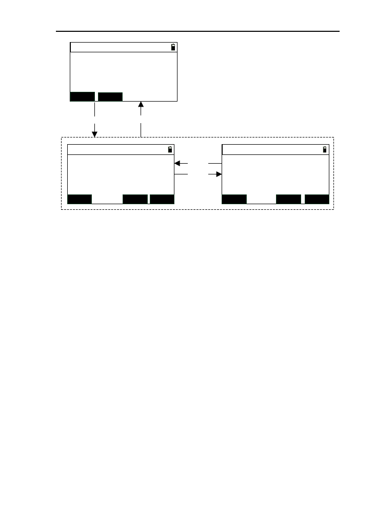
68
*[ENT] record
Offset/Angle->Result1/2
HR:
VZ:
SD:
*[HOT] to set T.H
Offset/Angle->Meas P
MSR1 MSR2
[MSR]
HR:
VZ:
SD:
ESC DSP ENT
*[ENT] record
Offset/Angle->Result2/2
ESC DSP ENT
[ESC]
(1)
Z:
N:
E:
(2)
[DSP]
[DSP]
m
m
m
m
35°34′17″
69°42′11″
209.456
m
37°22′45″
70°33′26″205.577
409.286
16.678
213.443
2) Pressing [▪] can enter the interface to change the target
height;
3) Aim at the measured point and press [MSR1] or
[MSR2] to start measuring. When finish the measuring,
enter the interface as shown in picture (2);
4) Aim at the target point, the data of angle, distance and
coordinate will be refreshed in time;
5) Pressing [DSP] can switch to check offset result data of
two pages;
6) Press [ENT] to enter the interface of recording the data.
7) Press [ESC] to return to the interface of
“Offset/Angle->Meas P”.
9.3 Double-Distance Offset Mode
It is specifically useful when the measured point is exactly
on the line of the two measurable points, as well as the distance
between measured point and the two measuring point is known.
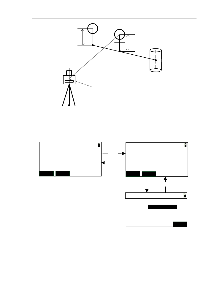
69
Instrument center
Measured point 2P2
Measured point 1P1
Target point
TGT
Station
Target height
Target height
1) In the offset menu, press [3] or press [ENT] after moving
the cursor to “Offset/2D” to enter the interface of
“Offset/2D->Pt.1” ,as shown in picture (1);
[MSR]
HR:
VZ:
SD:
*Take 1st
(1)
Offset /2D->Pt.1
MSR1 MSR2
HR:
VZ:
SD: *Take 2st
Offset /2D->Pt.2
MSR1 MSR2
(2)
P1-P2:
P2-TGT:
(3)
Offset /2D->Input
ENT
[MSR] [ESC]
【ESC】
35°34′17″
69°42′11″m
36°34′17″
69°43′11″m
3.893 m
m
2) Aim at the measured point 1 and press [MSR1] or
[MSR2] to start measuring. When finish the
measuring, enter the interface as shown in picture
(2);
3) Aim at the measured point 2 and press [MSR1] or
[MSR2] to start measuring. When finish the
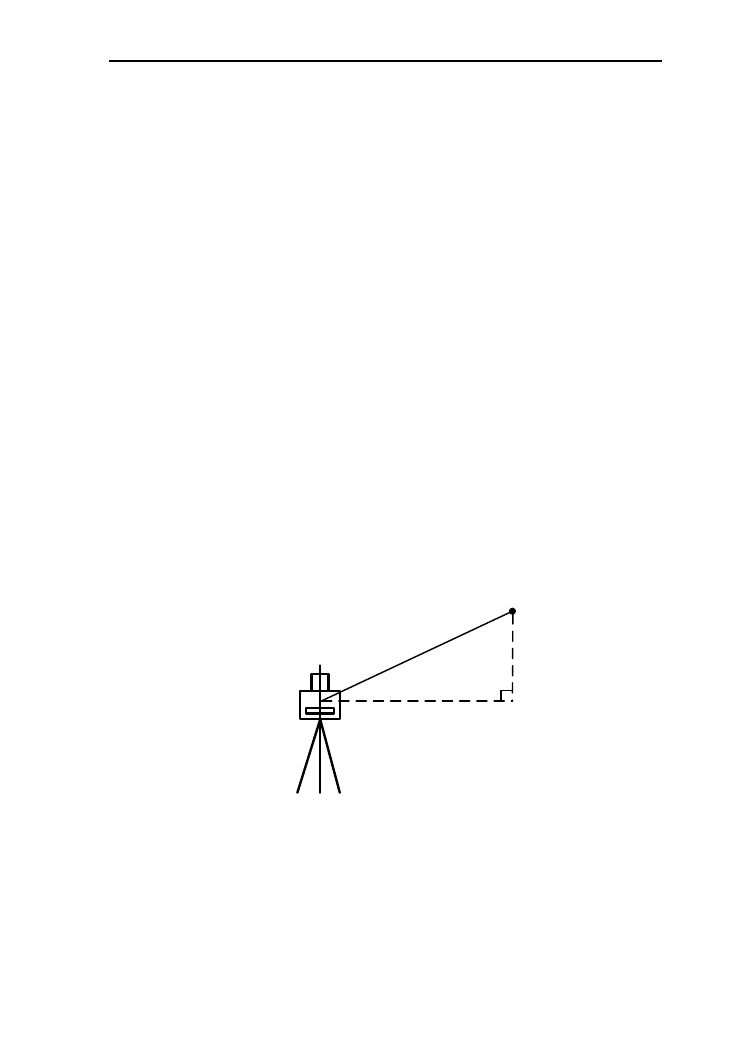
70
measuring, enter the interface as shown in picture
(3);
[Notice*] p1-p2: The measured horizontal
distance from point 1 to point 2.
P2-TGT: The horizontal distance from point 2
to target point.
4) After input the offset distance from measured point 2
to target point, enter the interface of recording data.
[Notice*] if the direction “P1->P2” and
“p2->TGT” is same, the value is positive or
negative;
5) Press [ESC] to return to the previous interface;
9.4 Horizontal distance offset Mode
This function is to calculate the angle, distance , coordinate
of target point just inputting the horizontal after angle
measurement. But it is just suitable for the near point
measurement.
HD
Target point
1) In the offset menu, press [4] or press [ENT] after
moving the cursor to “Offset/HD” to enter the interface
of “Offset/HD”, as shown below;
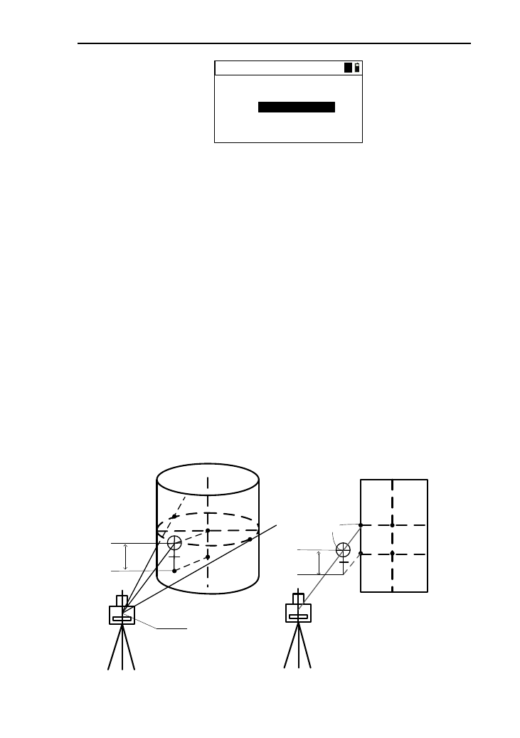
71
HR:
VZ:
HD:
*[ENT] after aim
Offset/HD 1
35°34′17″
69°42′11″m
2) Aim at the target point, and press [ENT] after input the
horizontal distance to enter the interface of recording
data to record the target point data;
3) Press [ESC] to enter the interface of “Offset” menu.
9.5 Column Offset Mode
This function is for measuring the coordinates of column
center and column radius.
Firstly, you should measure the azimuth angle and coordinate
of ‘P1’ on the cylinder under this mode. Then calculate the
horizontal distance, azimuth angle and coordinate of the cylinder
by measuring the surface points of tangency edge1 and edge 2.
If you want to calculate just measuring the azimuth of edge
1, you need to let the line between instrument center and point
p1 through the column center.
Edge 2
Center point
p1
Stereogram
p1 Center point
Target
height
+SD
Side elevation
Instrument center
Target
height
Edge 1

72
1) In the offset menu, press [5] or [ENT] after moving the
cursor to “Offset/Column” to enter the interface of
“Offset/Column->Prism” ,as shown in picture (1);
1) Aim at the prism, and press [MSR1] and [MSR2] to
start measuring .after a successful measurement
completed enter the interface as shown in picture (2);
2) Input the Prism deviation (+SD) and press [ENT] to
enter the interface as shown in picture (3);
[Notice*]: Prism deviation (+SD): the distance
difference between prism and P1;
3) Turn the instrument and aim at the edge 1 ,then press
[ENT] to enter the interface as shown in picture (4).you
can determine to calculate the result or measuring the
point 2 according to your need;
4) If the point P1 is just on the line from instrument to
center ,you can press [CALC] to calculate the result
and enter the interface shown in picture (5);
5) If the point p1 is not on the line from instrument to
center ,you can turn the instrument to aim at the edge
2 ,then press [EDGE2] to calculate the result and enter
the interface (5);
6) Press [ENT] to enter the interface of recording data.
After a successful saving data, return to the offset
menu.
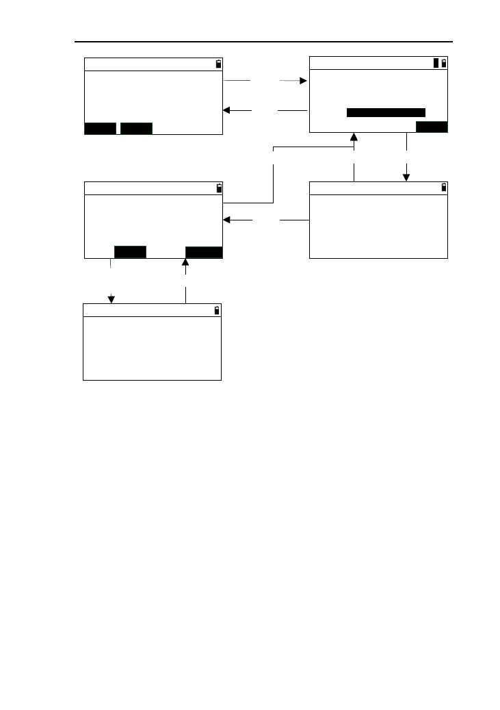
73
HR:
VZ:
SD:
*[HOT] to set H.T
Offset/Column->Prism
MSR1 MSR2
[MSR] HR:
VZ:
SD:
Input offset
(1)
+SD: 0.260
HR:
VZ:
Offset/Column->Edge2
*[ENT] after aim
HR:
VZ:
Offset/Column->Edge2
*Calc or aim egde2
N:
E:
Offset/Column->Result
*[ENT] to save
Z:
Radius:
[ENT]
(2)
[ESC]
[ESC]
EDGE2
CALC
[ENT]
[CALC]/
[EDGE2] [ESC]
m 134.663
82°11′24″
46°37′25″
m
m
46°37′25″
82°11′24″
43°52′10″
82°11′22″
47°26′11″
82°11′22″
ENT
[ESC]
(3)(4)
(5)
m
m
m
m
132.345
34.113
25.563
3.644
1
9.6 Slope Distance Offset Mode
When measuring operation, sometimes you need to modify
the slope distance, especially for the point where the prism is
placed. When using this function, you can modify the slope
distance, and then calculate the date of coordinate, angle and
distance of the target point. The picture as shown below:
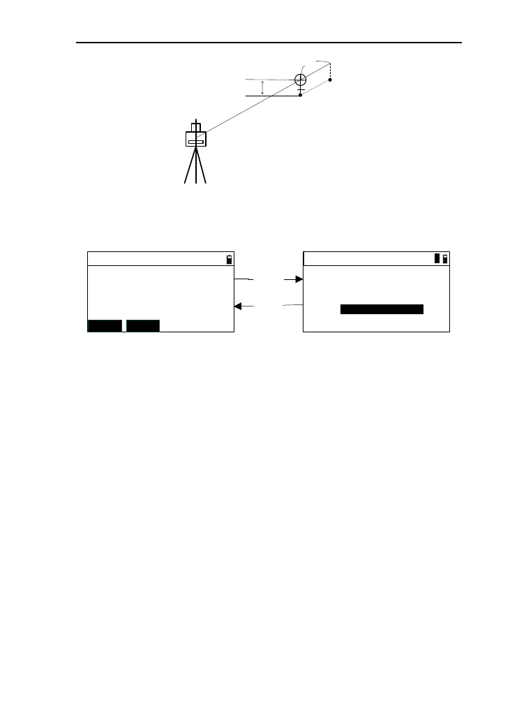
74
Target
height Target point
+SD
1) In the offset menu, press [6] or [ENT] after moving the
cursor to “Offset/SD” to enter the interface of
“Offset/SD->Meas” ,as shown in picture (1);
HR:
VZ:
SD:
*[HOT] to set T.H.
Offset /SD->Meas
MSR1 MSR2
[MSR] HR:
VZ:
SD:
Offset /SD->Input
+SD:
(2)
*[ENT] record
[ESC]
47°26′11″
82°11′22″m
m
47°26′11″
82°11′22″
0.260
134.663
(1)
m
1
2) Aim at the prism, and press [MSR1] and [MSR2] to
start measuring. After a successful measurement
completed enter the interface as shown in picture (2);
3) Input the offset “+SD”, and press [ENT] to enter the
recording interface, then the display is angle data,
distance, and coordinate of target point. After a
successful saving,return to the interface of offset menu;
4) Press [ESC] to return to the interface of “Offset
/SD->Meas”.
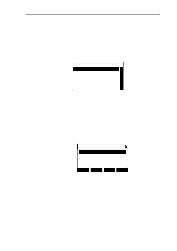
75
10. Data management.
This function is used to manage the measured data、code
data and you can view ,select, delete and edit the data.
In the basic interface, press [6] to enter the interface of data
menu, as shown below:
----Data-----
1.View file data
2.View known coord.
3.Input coord.
4.Code manager
5.Clear code
10.1 View file data
This function is to view the data of file selected, and
operate the data.
1) In the “Data” interface, press [1] or press [ENT] after
moving the cursor to “View file data” to enter the
interface of “Data list” ,as shown below;
Data list 1/1
SRH. ADD
DEL. EDIT
BS,200
ST,100
SS,200
CO,STATION
2) The data in the current file will be list in order , and the
first line in the list will displays “current page /total
pages”. Every page will display four piece of data. In
the front of “,”,it is the data type and behind the “,”,it is
name point or a content.
[Notice *]:
ST: Station data
BS: the data of backsight checking
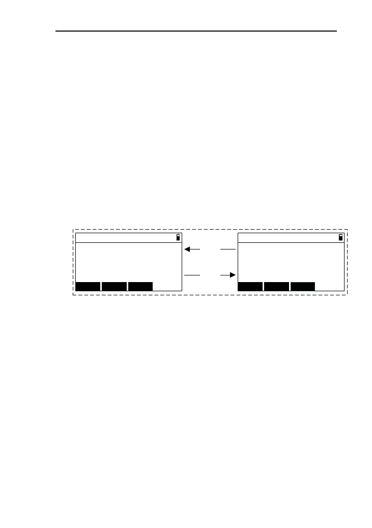
76
BK: the data of stationing by backsight angle.
SA: angle data
SS: measured data
MP:The input data of coordinate
CO:Comment data
3) Pressing [▲] or [▼] can move the cursor. When
moving the cursor to last line, press [▼] to turn to the
next page. When the moving the cursor to the first
line,press [▲] to turn to the previous page;
4) Pressing [◄] or [►] can turn the page up or down;
5) Press [ENT] to view the information of data where the
current cursor to.Here ,as an example of station data ,as
shown below:
STN 1/2
STN:
I. H:
BS:
AZ: DSP
STN 2/2
Z:
Code:
DSP
[DSP]
[DSP] E:
N:
FIRST LAST
FIRST LAST
m
m
m
m55.369
125.354
1.248
road
100
1.58
200
45º12'35"
① Press [FIRST], you can view the information of
first piece of data;
② Press [LAST], you can view the information of
last piece of data;
③ Press [DSP], you can view two pages information
of current data. (Some data type just have one
page information, so, the key [DSP] will not
appear.);
④ Press [▲] ,you can view the information of
previous piece of data;
⑤ Press [▼] ,you can view the information of next
piece of data;
⑥ Press [ESC] to return to the data list;

77
6) Press [SRH.] to enter the interface of “Input filters”, as
shown below:
Input filters
Type:
Pt.N:
Match
▲
▲
1
① When the “Type” is “Match”, you need to input
the point name with matching the selected point
name. After searching, return to the data list with
the cursor to current searched point;
② You can press to [▲] or [▼] to move the cursor to
“Type” to select “Fuzzy” , and if the result
selected is more than one piece , a point list will
appears for you to select .
7) Press [DEL.] with a prompt box “Delete?”.If you press
[ENT],then delete (some data type can’t be deleted but
there will be a prompt).If you press [ESC],then return
back to the data list;
8) Press [ADD] to enter the interface of “Input coord.”,
and the specific operation refers to chapter 10.3. press
[ESC] to return to the data list;
9) If you select the current data with the type “MP”, press
[EDIT] to enter the interface of “Edit coord.”. In this
interface, you can edit point name “Pt.N” and “Code”.
The data with other types will can’t be edited and with
a prompt “Only input coords can edit”;
10) Press [ESC] to return to the data management menu.
10.2 view known coordinate.
In the instrument memory, there is a fixed known
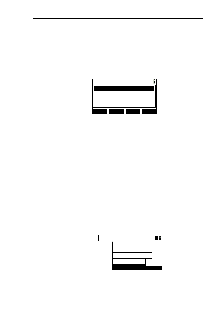
78
coordinate file, and the name is “PCOOR.COR”, which stores
the known coordinate data. This function is used to view the
known coordinate data and operate the data.
1) In the data management menu ,press [2] or press [ENT]
after moving the cursor to “View known coord.”,as
shown below:
Known list 1/1
SRH. ADD
DEL. CLR.
MP,200
MP,100
MP,201
MP,202
2) Specific operation refers to chapter 10.1 and without
edit function;
3) Press [CLR.] with a prompt “Clear?.If press [ENT],
clear the data of known coordinate file. If press [ESC] ,
return to the data list;
4) Press [ESC] to return to the data management.
10.3 Input known coordinate
This function is to input coordinate data to known
coordinate files.
1) In the data management menu, press [3] or press [ENT]
after moving the cursor to “Input coord. ” to enter the
interface of “Input coord.”, as shown below:
Pt.N:
Code:
Input coord.
101
ROAD LIST
123.254
362.145
1.258
m
m
m
Z:
E:
N:
1
2) After input the “N”, “E”, “Z”, “Pt.N”, “Code”, press
[ENT] at the code input box with a prompt “Finished”;
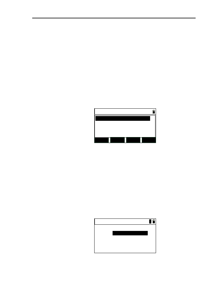
79
3) When the cursor to the “Code” input box, the [LIST]
button will appear and you can retrieve code;
4) Press [ESC] to return to data manager menu.
10.4 Code manager
In the instrument memory, there is a fixed known code file,
whose name is “CODELIST.LST” to store code data.
1) In the data menu ,press [4] or press [ENT] after moving
the cursor to “Code manager ” to enter the interface of
“Code”, as shown below:
Code 1/1
SRH. DEL LAST
ADD
BTT
GENGLE
TREE
2) After you press [LAST], the key name “LAST” will be
changed to “FIRST”, and the cursor will be moved to
the last piece of data. If you press again, the cursor will
be moved to the first piece of data;
3) Press [ADD], enter the interface of “Add code”, as
shown in picture below. You can save the input data by
pressing [ENT] and press [ESC] return to code list
interface;
Add code
Code:
*[ENT] to add
1
4) For the other operations, refer to chapter 10.1;

80
10.5 Clear code
This function is for clearing the data in code file.
In the data management menu, press [5] or press [ENT]
after moving the cursor to “Clear code”, then a prompt appears
“Clear?” to make sure whether you want to clear code .If you
want to clear code ,just press [ENT],after clearing the code,
return to data manage menu, if not return to the data
management directly.
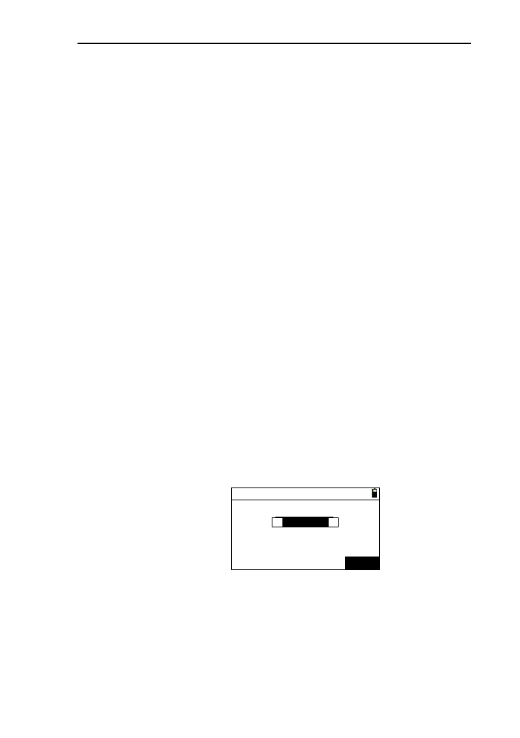
81
11 Menu
11.1 File manager
There are some different file types in the instrument
memory.
.DAT: Working data file
PCOOR.COR: Known coordinate file
CODELIST.LST: Code file
.LSH: Horizontal alignment file
.LSV: Vertical alignment file
Among them, .working data file, alignment file can exit
multiple, but others can exit as a single and fixed file.
File manager is used to manage the working data file.
1) In the basic interface, press [MENU] to enter the menu
interface , then press [1] or press [ENT] after moving the
cursor to “File manager” to enter the interface of “Select
disk”, if you have inserted the USB disk , then press [◀] or
[▶] to select disk ,as shown in picture (1). After you select
disk, enter the interface of “File manager”, as shown in
picture (2) ;
Select disk
(1)
Disk A:Flash
▲
▲
ENT
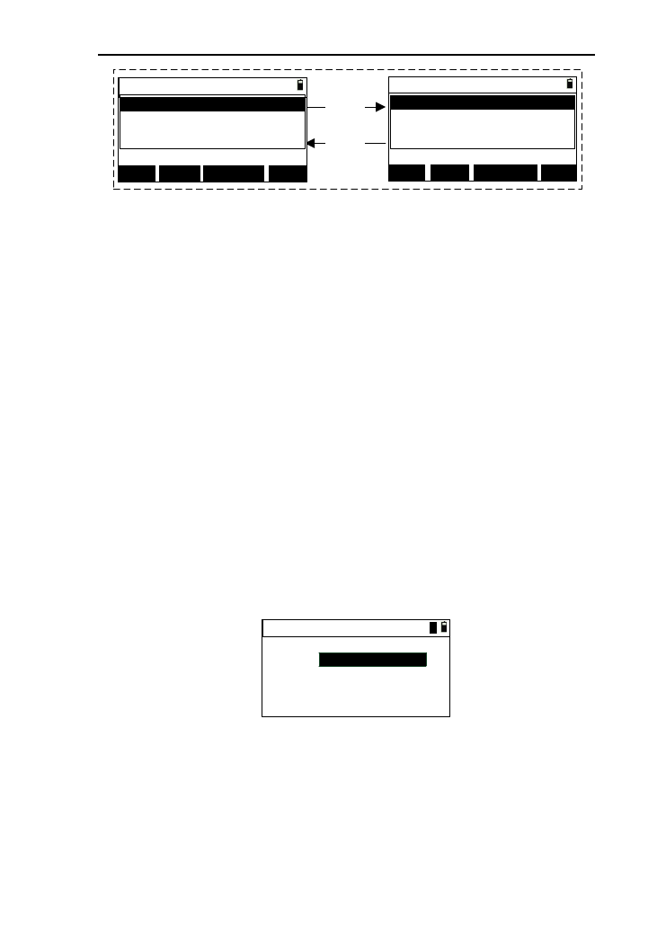
82
File manager
DEL. FORMAT
INFO P1↑
[P1↑]
[P2↓]
★A:130606-1 △A:130606-1
130606-1
130606-2
130606-3
File manager
NEW LIST
JOB P2↓
★A:130606-1 △A:130606-1
130606-1
130606-2
130606-3
(2)
2) The files in the selected disk will be list on the display ,and
you can press [▲] or [▼] to move the cursor to select file;
[Notice*]:
The display which behind“★” is the file name of
current working file in the selected disk .
The display which behind“△” is the file name of
current working file which is used to retrieve
coordinate in the selected disk .
3) After pressing [P2↓] , the key name changed to [P1↑] and
turn to the second page, then press [P1↑] ,turn to the first
page;
4) Press [NEW] to enter the interface of “New file”,as shown
in picture below. After input point name, you can press
[ENT] to a create new file, if it exits , a prompt “File exits”
will appear and the back to the file manager interface;
New file
File :
1
5) Press [JOB] to set the selected file as current working file;
6) Pressing [LIST] can set the selected file as current working
file;
7) Press [DEL.] with a prompt “Delete?”. If press [ENT] ,then
delete the selected file and return to file manager interface
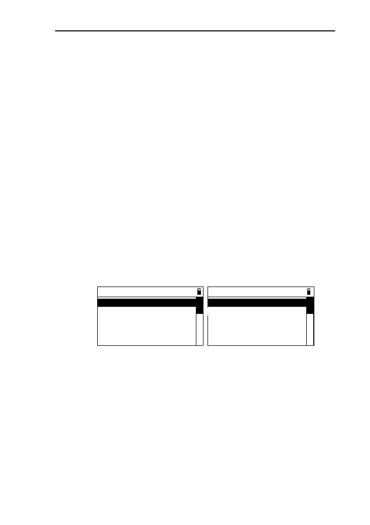
83
(the current file can’t be deleted),if press [ESC],then return
to file manager interface directly;
8) Pressing [INFO] can view the selected information, and
press [ENT] or [ESC] to return to the file manager
interface;
9) Press [FORMAT] with a prompt “Erase all data, continue?”
appearing (you must be very careful),if you press
[ENT],then the flash disk will be erased and the other data
will be cleared except system parameters;
10) Press [ESC] or [ENT] to return to menu interface.
11.2 Setting
For the different measurement environment and work , you
can set the instrument. In the interface of the basic interface,
press [2] or press [ENT] after moving the cursor to “Setting” to
enter the interface of instrument setting menu, as shown in
picture below:
----Setting----
1.Angle
3.Coordinate
2.Distance
4.Unit
5.Communication
----Setting----
6.Others
7.Factory reset
8.Upgrade
11.2.1 Angle Setting
1) In the instrument menu, press [1] or press [ENT]
after moving the cursor to the “Angle” to enter the
interface of “Angle setting”, as shown in picture
below:

84
Angle setting
VA:
Res.:
HA:
H Beep:
▲
▲
▲
▲
▲
▲
▲
▲
HR
Zenith
1″
ON
2) After set one parameter ,press [ENT] or [▼] to move
the cursor down and you can also press [▲] to move
the cursor up;
3) Pressing [◄] or [►] can change the potion of option
box;
4) After complete to set the last one, press [ENT] to save
the settings and return to the previous interface.
5) HA: horizontal angle, there are two options “HR” and
“HL”;
6) VA: Vertical angle, you can select “Zenith”, “HA 0”,
“Elev”, “Slope”;
7) Res.:Angular Precision. You can select “1″”,“5″” or
“10″” when the unit of angle is “DMS”; You can
select “0.0002gon”,“0.001gon″” or “0.002gon” when
the unit of angle is “gon”;and You can select
“0.005mil”,“0.02mil″” or “0.005mil” when the unit
of angle is “mil”;
8) H beep: you can select “ON” or “OFF”.
11.2.2 Distance setting
1) In the setting menu, you can press [2] or press [ENT]
after moving the cursor to “Distance” to enter the
interface of “Dist. setting”,as shown in picture below:
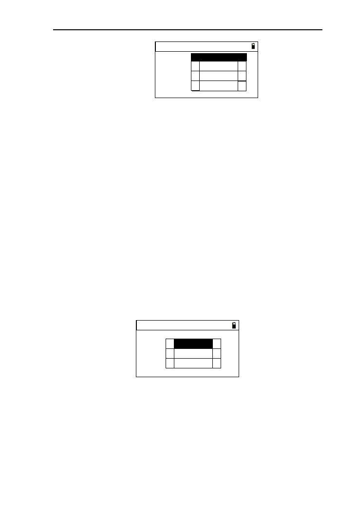
85
Dist. setting
T-P adj:
Sea:
Scale:
C&R adj:
1.000000
▲
▲
▲
▲
▲
▲
ON
OFF
0.14
2) Scale: to input scale, the range is 0.99~1.10.if the scale
beyond the range, the other value can be ignored;
3) T-P adj: you can select “ON” or [OFF];
4) Sea: you can select “ON” or “OFF”;
5) C&R adj: you can select “OFF”, “0.14” or “0.2”;
[Notice *]
T-P adj: the correction of temperature and atmospheric
Sea:the correction of Earth Curvature.
C&R adj: The Correction of the Atmospheric refraction
and the Earth Curvature.
11.2.3 Coordinate setting
1) In the setting menu, press [3] or press [ENT] after
moving the cursor to “Coordinate” to enter the
interface of “Coord:”,as shown in picture below:
Coord:
Order:
Note:
Dsp:
▲
▲
▲
▲
▲
▲
NEZ
XYZ
NORMAL
2) Order: you can select “NEZ” and “ENZ”;
3) Note: when the order is “NEZ”,you can select
“XYZ”,”YXZ”,or “NEZ”;when the order is “ENZ”,you
can select “XYZ”, “YXZ”,or“ENZ”. This parameter
will affect the coordinate title and coordinate display
order;
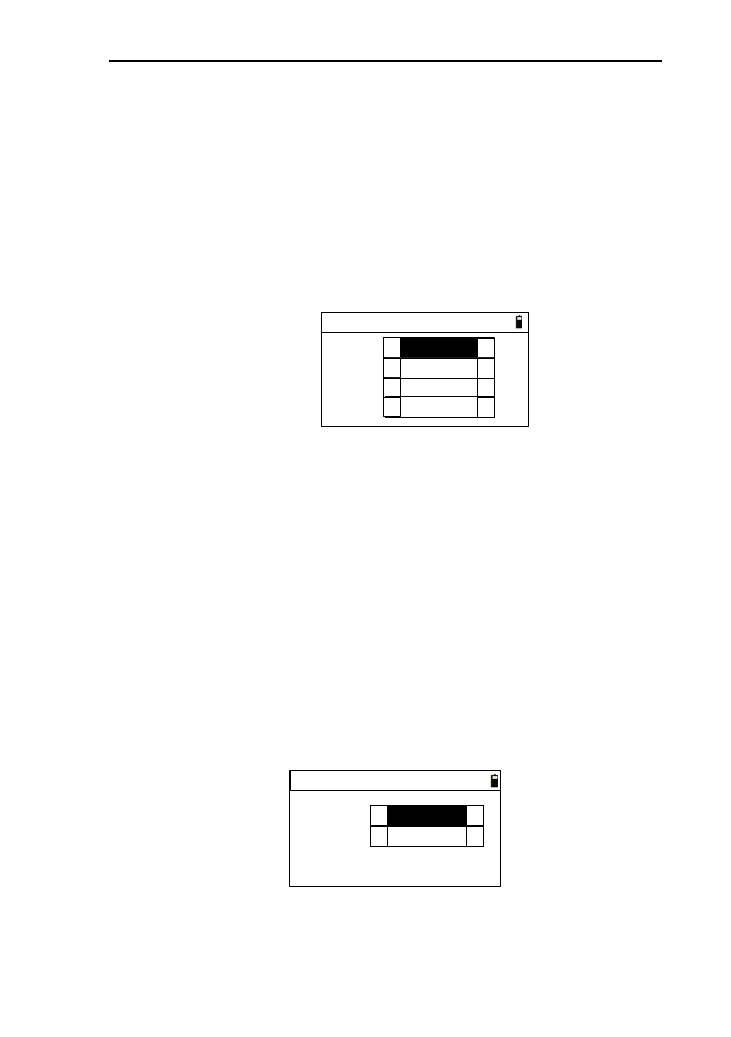
86
4) Dsp: Display. You can select “Normal”, “Slow”,
“[ENT]”,or “FAST”. This parameter can control the
automatic display of the retrieving dialog box .
11.2.4 Unit setting
1) In the setting menu, press [4] or pres [ENT] after
moving the cursor to “Unit” to enter the interface of
“Unit setting”,as shown in picture below:
Unit setting
Dist:
Temp.:
Press:
Angle:
▲
▲
▲
▲
▲
▲
▲
▲
DMS
m
℃
hPa
2) Angle : you can select “DMS”, “GON”,or “MIL”;
3) Dist.:Distance.you can select “m”, “US-Ft” or “I-Ft”;
4) Temp.: you can select “℃”, or “℉”;
5) Press: Pressure .you can select “hPa”,“mmHg” 、
“inHg”,“mBa”,“Psi”.
11.2.5 Communication setting
1) In the setting menu, press [5] or press [ENT] after
moving the cursor to “Communication ” to enter the
interface of “Communication”, as shown in picture
below:
Communication
Baud:
▲
▲
▲
▲
Port: Cable
9600
2) Port: there are “Cable” and “B.T.” (this option just for
the instrument which is equipped with blue tooth) to be
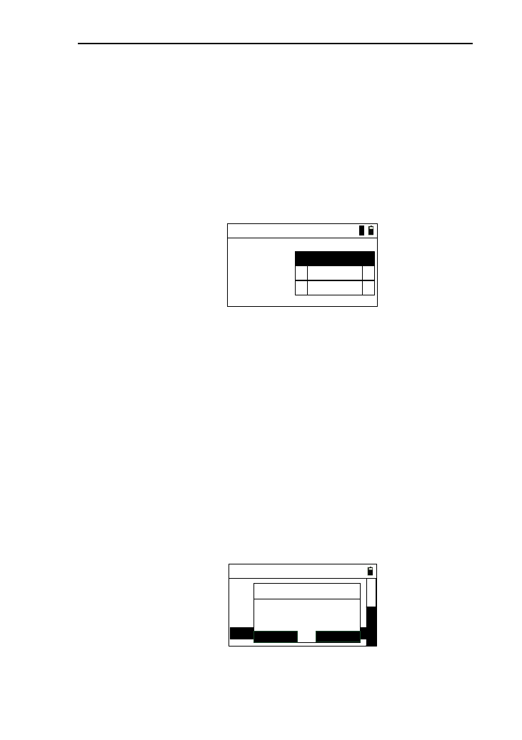
87
selected;
3) Cable: there are “2400”, “4800”, “9600”, “19200”,
“38400”, “57600”, “115200”.
11.2.6 Other settings
1) In the settings menu, press [6] or press [ENT] after
moving the cursor to “Others” to enter the interface of
“Others”, as shown in picture below:
Others
Poweroff:
S-O Pt.N: 1000
▲
▲
1
Pt.N Check:
Never
▲
▲
ON
2) S-O Pt.N: used for “S-O coord.”. The value set will be
added to the point name when saving the measured
point ,and the range is 0~9999;
3) Power off : there are “Never”, “5min”, “10min”,
“20min”, “30min” to select;
4) Pt.N Check: for Checking homonymous points. There
are “ON” or “OFF”.
11.2.7 Factory reset
1) In the setting menu, press [7] or press [ENT] after
moving the cursor to “Factory reset” , then a prompt
box appears as shown in picture below:
----Setting----
4. Unit
6. Others
5. Communication
7. Factory reset
8. Upgrade
3. Coordinate
ENT
ESC
Reset to
factory setting ?
Info
D
2) If press [ENT], restore the instrument to factory setting
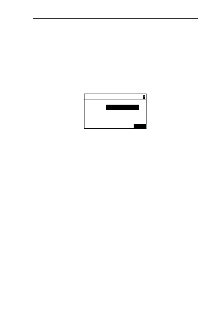
88
and shut down it automatically;
3) If press [ENT], return to the setting interface.
11.2.8 Upgrade
1) This function is for you to upgrade the software of the
instrument. In the setting menu, press [8] or press [ENT]
after moving the cursor to “Upgrade” to enter the
interface as shown in picture below:
Software upgrade
PIN:
ENT
2) Input “PIN” (82543), then press [ENT] with the
instrument shutdown;
3) Connect the instrument to the computer through serial
port connector. Open the hyper terminal softwareand
set up the correct port. Then set ‘Bits per second ’ to
115200 and ‘ Flow control ’ to ‘ None ’. Finally, when
all operations above are done, press [ENT] to update.
Mention that the computer must be installed with
correct drivers;
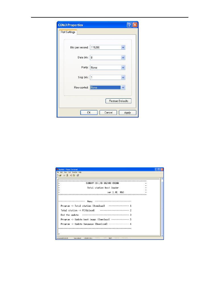
89
4) Press power button on the instrument. The page of hyper
terminal is as followed;
Note: you must be specifically cautious when updating. As
soon as you choose to update, the instrument will enter
updating mode. If pressing key ‘3’ under the page
shown below, the previous program may be resumed.
5) Press key ‘1’ on the keyboard. The instrument enters
waiting state for sending programs. After the state,
click‘Send File’ on the computer;
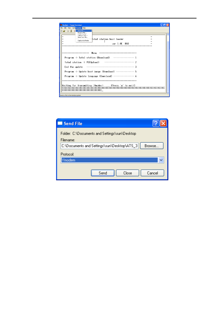
90
6) Select the new version of total station software and
click ‘ Send ’ on the computer;
7) Then the computer displays the process of sending.
After finishing updating, display the operation menu
again .You can press [5] to update boot image and
press [6] to update language;
8) After update program, boot image, language, press [3]
to end the update and press power button to turn on the
instrument to run the updated program.
11.3 Data management
See the Chapter 10.
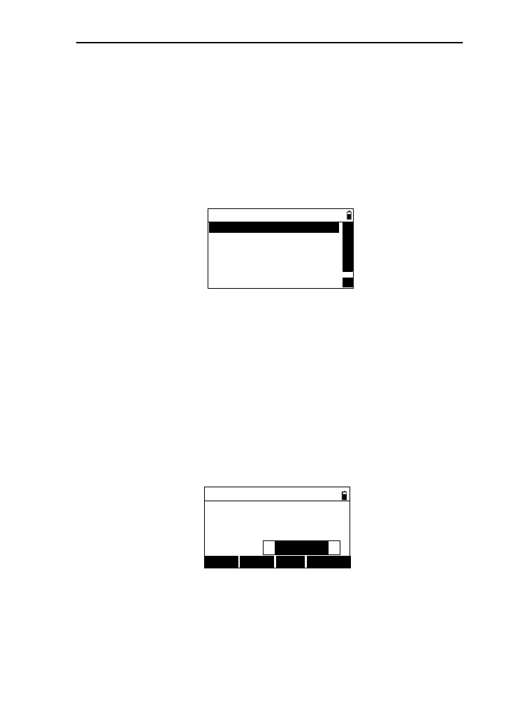
91
11.4 Import and Export
Not only most of the data in the instrument are needed to be
exported to computer to be processed, but also some edited date
are needed to be imported to instrument to be used quickly。
In the menu interface, press [4] or press [ENT] after
moving the cursor to “Import/Export” to enter the interface of
“Import/Export” ,as shown in picture below:
1.Export=>Port
△
△
2.Export=>UDisk
3.Import coord<=Port
4.Import coord<=UDisk
6.Import code<=UDisk
----Import/Export----
5.Import code<=Port
11.4.1 Export to PC
You can export the working file or known coordinate data
to the transport software from PC.
1) In the “Import/Export” menu, press [1] or press [ENT]
after moving the interface of “Export=>Port” to enter
the interface of “Export data”, as shown in picture
below. The default file name is the current working
file;
Export data
Baud.:
File:
Number:
115200
0
JOB1.DAT
↓EXPORT
↑FILE
Format:
▲
▲
Sunway
2) Pressing [↑] or [↓] can change the baudrate of the
communication. You must keep the baudrate of
instrument and it of transport software, or you will
export data unsuccessfully;
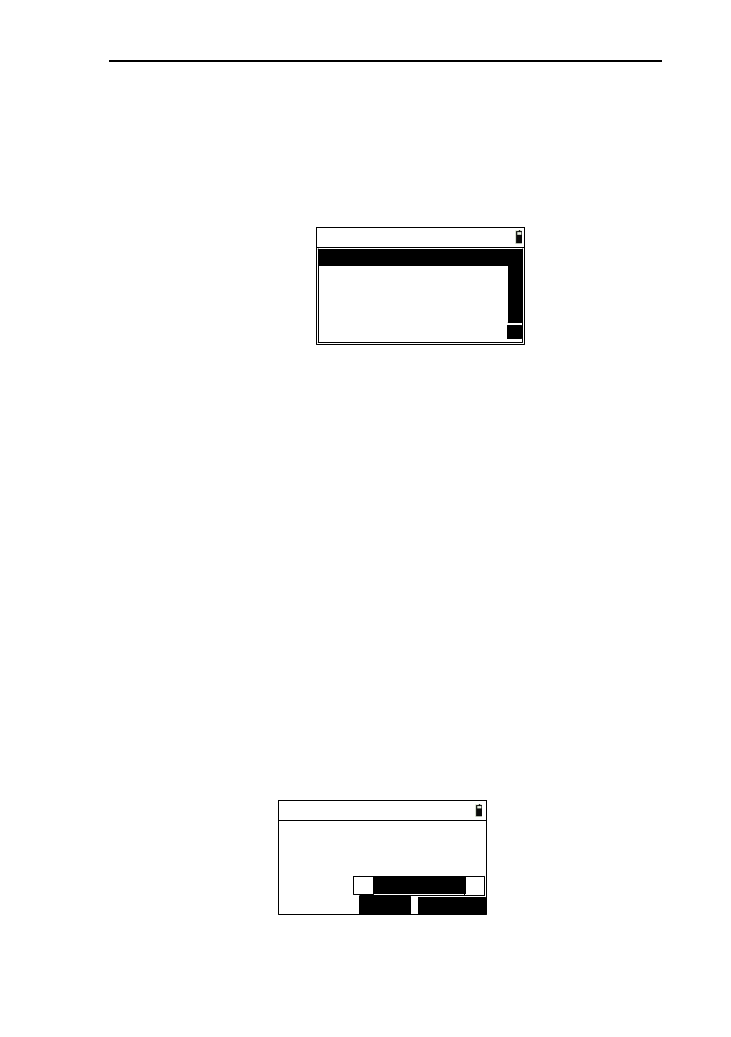
92
3) Press [FILE] to enter the interface of “Select
disk” .after select disk, enter the interface of “Select
file”,as shown in picture below. After selecting the file ,
press [ENT] to return to the interface of “Export data”
and refresh the “File”;
Select file
PCOOR .COR
JOB2 .DAT
JOB3 .DAT
JOB4 .DAT
5 .DAT
△
△
4) After connecting PC, press ‘ Recieve ’ on the transport
software from PC, and press [EXPORT] to start export
data with the display of “Number” refreshed. A prompt
will appears when finishing exporting;
5) Press [ESC] to return to “Import/Export” menu.
11.4.2 Export to U disk
This function can transport the work file and known
coordinate file to the inserted U disk.
1) In the “Import/Export ” menu, press [2] or press [ENT]
after moving the cursor to “Export=>UDisk” to enter
the interface of “Export data ”(you must insert the U
disk first or you will not allowed to enter the next
interface) as shown in picture below, the default file
name is the current file name;
Export data
Dest.:
File:
Number:
EXPORT
FILE
JOB2.TXT
JOB2.DAT
0
Format:
▲
Sunway
▲
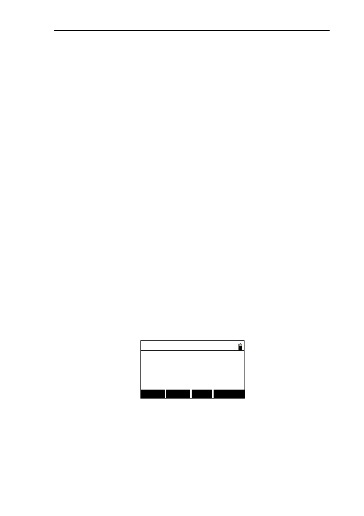
93
2) The “Dest.”meas destination file whose name must be in
accordance with the selected file, whose extension is
“.TXT”;
3) Pressing [FILE] can reselect the file which will to be
exported.Here can only select the file in instrument
internal;
4) Press [EXPORT] to start to export data. In the
processing of the exporting, the number is refreshing
constantly until finishing the exporting. The exported
file needs to be opened and proceed in the transport
software.
5) Press [ESC] to return to “Import/Export” menu.
11.4.3 Import coordinate from PC
You can import the coordinate date from PC to the working
file or known coordinate data by transport software.
1) In the “Import/Export” menu, press [3] or press [ENT]
after moving the interface of “Import coord<=Port” to
enter the interface of “Import”, as shown in picture
below. The default file name is the current working
file;
Import
Baud.:
File:
Number:
115200
0
JOB1.DAT
↓IMPORT
↑FILE
2) Pressing [↑] or [↓] can change the baudrate of the
communication .You must keep the baudrate of
instrument and it of transport software, or you will
import data unsuccessfully;
3) Press [FILE] to enter the interface of “Select disk”;
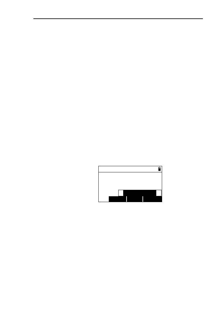
94
4) After connecting PC,press ‘ Send ’ on the transport
software from PC,and press [IMPORT] to start import
data with the display of “Number” refreshed. A prompt
will appears when finishing importing;
5) Press [ESC] to return to “Import/Export” menu.
11.4.4 Import coordinate from U disk
This function can import the data completed according to
the request coordinate format in U disk to work files and known
coordinate files.
1) In the “Import/Export” menu, press [4] or press [ENT]
after moving the cursor to “Import coord<=UDisk” to
enter the interface of “Import”(you must insert the U
disk first ,or you will not allowed to enter the next
interface) as shown in picture below, the default file
name is the current file name;
Import
IMPORT
SRC. FILE
Src:
File:
Number: JOB2.DAT
0
COOR.TXT
Format:
▲
PT,N,E,Z,Code
▲
2) The “Src” is the text file in the U disk, which stores
coordinate data. Press [SRC.] to enter the interface of
“Select file”, see the chapter 11.4.1;
[Notice*] : The format you can select “PT,N,E,Z,Code”
or “PT,E,N,Z.Code”, which means “Point name,
Easting, Northing, Code”. The text file in the U disk
must be according to the selected format, and each line
must end with ENTER+LINEFEED, otherwise, the last
line must end with ENTER;
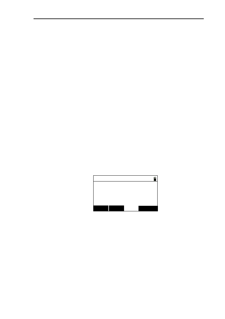
95
3) Pressing [FILE] can reselect the file which will to be
exported.Here can only select the file in instrument
internal;
4) Press [IMPORT] to start to export data. In the
processing of the importing, the number is refreshing
constantly until finishing the importing;
5) Press [ESC] to return to “Import/Export” menu.
11.4.5 Import code from PC
You can import the coordinate date from PC to the working
file or known coordinate data by transport software and transport
line.
1) In the “Import/Export” menu, press [5] or press [ENT]
after moving the interface of “Import code<=Port” to
enter the interface of “Import”, as shown in picture
below. The default file name is the code file, which
can’t be changed;
Import
Baud.:
File:
Number:
115200
0
CODELIST.LST
↓IMPORT
↑
2) Pressing [↑] or [↓] can change the baudrate of the
communication .You must keep the baudrate of
instrument and it of transport software, or you will
import data unsuccessfully;
3) After connecting PC, press ‘Send’ on the transport
software from PC, and press [IMPORT] to start import
data with the display of “Number” refreshed. A prompt
will appears when finishing importing;
4) Press [ESC] to return to “Import/Export” menu.
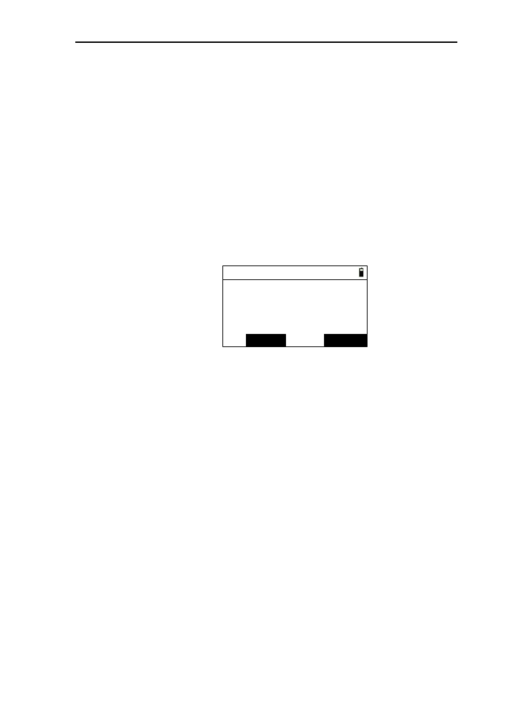
96
11.4.6 Import code from U disk
This function can import the code data completed according
to the request code format in U disk to code files in the
instrument.
1) In the “Import/Export” menu, press [6] or press [ENT]
after moving the cursor to “Import code<=UDisk” to
enter the interface of “Import” (you must insert the U
disk first or you will not allowed to enter the next
interface) as shown in picture below, the default file
name is the current code file name;
Import
IMPORT
SRC.
Src:
File:
Number: CODELIST.LST
0
CODELIST.TXT
2) The “Src” is the text file in the U disk, which stores
code data. Press [SRC.] to enter the interface of “Select
file”, see the chapter 11.4.1;
[Notice*]
The format of the content in the text file in the U disk
must be fixed as “CODE” and each line must end with
ENTER+LINEFEED, otherwise, the last line must end
with ENTER;
3) Press [ESC] to return to “Import/Export” menu.
11.4.7 Mini USB connect
The Mini USB cable, one end inserted into the instrument,
the other end inserted into the computer, as shown in picture
below:

97
USB connected
Info
ENT
On the computer, the instrument is identified as a U disk
and you can copy the files;
[Notice *]: The file “eepromd.sys” is system parameter file,
which can be cut;
After copy the work file and coordinate file, you can open
them by transport software directly. After ending the connecting,
unplug the Mini USB cable, then press [ENT] to running the
program continually.
11.5 User key definition
Our instrument has been equipped with two user key, which
are the key [1] and [2]. Each user key can be defined as different
shortcut function. In the menu of user key, which key you select,
will be define as the function what you want. After defining, you
can press [1] or [2] to enter the defined function directly in the
“user key” menu.
The functions are defined to the user key as follow:
●File manager
●BS reset.
●Offset
Menu
Dist
Angle
2D
HD
Column
SD
●Program
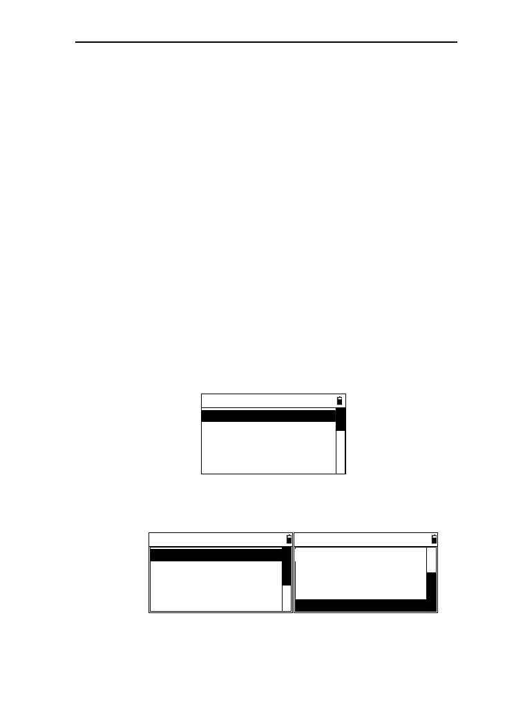
98
Prog. [Menu]
Project
Arc
MLM(AB-AC)
MLM(AB-BC)
REM
Vert. plane
Bevel
Area & Per.
Road D & S-D
●Temp. & Press
●Import & Export
●None
Here, for example, defining user key [1]:
1) In the interface of “Menu”, press [5] or press [ENT]
after moving the interface of “User key” to enter the
interface of defining user key;
----User key----
1. User keys 1
2. User keys 2
2) Press [1] or [ENT] after moving the cursor to “1.User
keys 1” to enter the interface of “User keys 1”;
User keys 1
BS reset.
Offset->
Temp. & Press
Program->
File Manager
User keys 1
Temp. & Press
Program ->
Offset->
Import & Export
None
3) Press [▲] or [▼] to move the cursor to the needed
defined function;
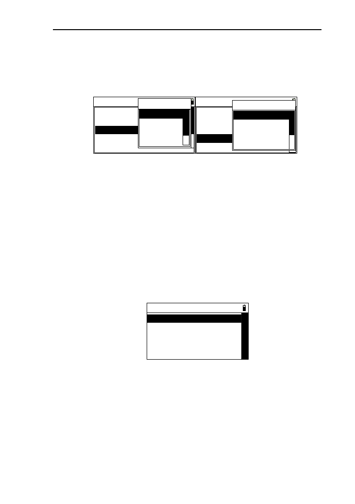
99
4) When the cursor is moved to “Offset->” or
“Program->”, you can press [ENT], then a prompt of
sub-functions will appear and display, as shown in
picture below;
User keys 1
BS reset.
Offset->
Temp. & Press
Program->
File Manager Offset
Menu
Dist
Angle
2D
User keys 1
BS reset.
Offset->
Temp. & Press
Program->
File Manager
Prog./Opti
Proj.[Menu]
Project
Arc
MLM(AB-AC
5) Press [ENT] to select the function to define the user
key and return to the User keys menu.
11.6 Calibration
This function is used to calibrate the measurement
parameter of instrument.
In the basic measurement interface, press [ENT] to enter
the interface of menu, then press [6] or press [ENT] after
moving the cursor to “Calibration” to enter the interface of
“Calibration”, as shown in picture below:
----Calibration----
1. Ajust I.E
3. Adjust X
2. Input INS. const.
4. Adjust Y
11.6.1 Adjusting index error(I.E)
1) After enter the interface of calibration menu , press [1]
or press [ENT] after moving the cursor to “Adjust I.E”
with a prompt “Take positive” appearing, as shown in
picture below;
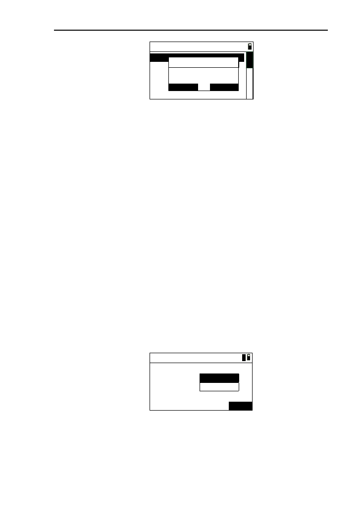
100
----Calibrate----
1. Adjust I.E
2. Input INS. const.
3. Adjust X
4. Adjust Y
Take positive
ESC ENT
Info
2) Aim at the target in face left, then press [ENT];
3) The instrument measures the vertical angle
automatically with a prompt displaying angle , then you
can press [ENT];
4) A prompt “Take reverse” appears, you can aim at the
target in face right, then press [ENT];
5) The instrument measures the vertical angle and
calculates and displays the index error automatically
to ask you whether want to save the result ,you can
press [ENT] to save and exit the interface(the index
error completed) ,or press [ESC] not to save (the index
error keep the original value.).
11.6.2 Input the instrument constant
1) In the calibration menu, press [2] or press [ENT] after
moving the cursor to “Input INS. const.” to enter the
interface of “Config” ,as shown in picture below:
Config
Add C:
Mul C:
SAVE
5
0mm
1
mm
2) Input parameter;
[Notice*]:
The range of additive constant (ADD C) is
“-99~+999mm”;
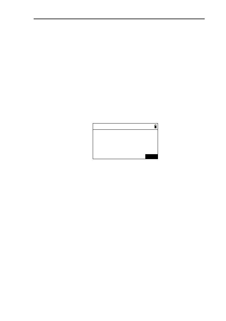
101
The value of multiplication constant (Mul C) is
zero. The two settings will affect the measured
data.
3) Press [Save] to save the setting of instrument constants
and return to the “Calibration” menu;
4) Press [ESC] to return to the “Calibration” interface.
11.6.3 Calibrate the tilt X
1) In the “calibration” menu, press [3] or press [ENT] after
moving the cursor to “Adjust X” to enter the interface of
“Adjust tilt X”;
HA:
VA:
Tilt:
*F1 Up 3′
ENT
45°00’00”
90°01’55”-3
Adjust TiltX
2) After leveling the instrument, aim at the target F1 in the
collimator in face left, record the current vertical angle as
V0.Set the vertical angle to V0+3′with the help of the
vertical tangent screw. Adjust the screw C to aim at the
target precisely. Press [ENT] to confirm after a stable
readout appears;
3) Set the vertical angle to V0-3′with the help of the vertical
tangent screw. Adjust the screw C to aim at the target
precisely and press [ENT] to confirm after a stable readout
appears;
4) Set the vertical angle to V0 with the help of vertical tangent
screw. Adjust the screw C to aim at the target precisely;
5) Aim at the target F2 in the collimator with reverse telescope
and record the current vertical angle as V1.Set the vertical
angle to V1-3′with the help of the vertical tangent screw.
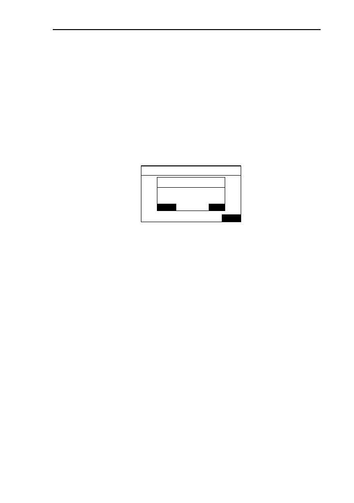
102
Adjust the screw C to aim at the target precisely and press
[ENT] to confirm after a stable readout appears;
6) Set the vertical angle as V1+3′with the help of the vertical
tangent screw. Adjust the screw C to aim at the target
precisely and press [ENT] to confirm after a stable readout
appears;
7) After completed the operations, the result will be displayed,
as shown in picture below, you can press [ENT] to save the
result and return to “Calibrate” menu.
HA:
VA:
Tilt: 正镜下倾3分
ENT
225°00’00”
227°01’22”
-240
Zero: 3 Save?
ESC ENT
X CO: -0.7989
Adjust TiltX
Info
Notes: “ X CO” (linear coefficient) must be less than 1.5;
“Zero” (zero position) is normally between -20 and
+20, otherwise the compensator (tilt) must be
adjusted mechanically.
11.7 Date/Time
There is an independent timer-modul, even though you pull
out the battery, it also runs. You can calibrate the time with this
function.
1) In the menu interface, press [7] or press [ENT] after moving
the cursor to “Date/Time” to enter the interface of “Date &
Time”, as shown in picture below, the time displayed in the
interface is the time at the moment;
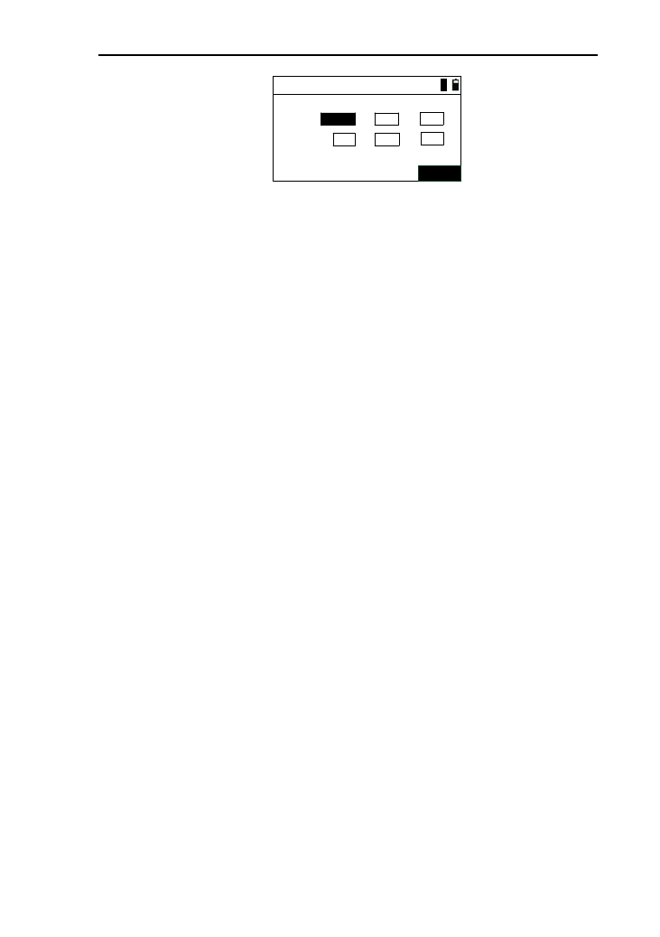
103
Date & Time
Date:
Time:
Save
2013
08
12 25
--
:18 16
:
1
2) After each input data, press [ENT] or[▼] to moving the
cursor down, and you can also move it up;
[Notice*]: The input value of time and date must be
effective.
3) After inputting, press [Save] to set the input data as the
current date and time, then return to menu interface;
4) Press [ESC] to cancel calibration and return to menu
interface.
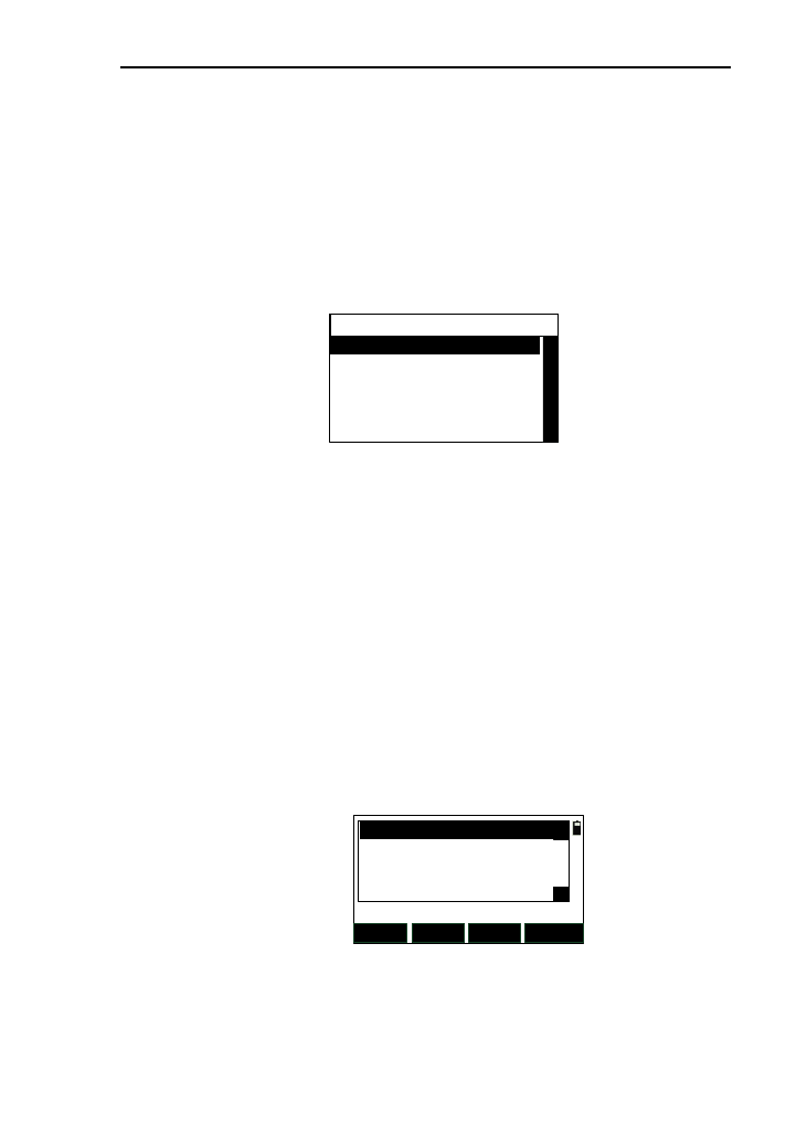
104
12 Roadway
This function is used to manage the road file, input road
data, stake out road, etc.
In the basic interface, press [4] to enter the “program” menu,
then press [9] to enter the interface of “Road ” menu,as shown in
picture below:
----Road-----
1. Road file manager
2. HC list
3. VC list
4. S-O road
△
12.1 Road file manager
There are two type road file,which are horizontal alignment
file and vertical alignment file. Every road implicitly exists with
the same name of two types of files.
1) In the road menu, press [1] press [ENT] after moving
the cursor to “Road file manager” to enter the interface
of road file manager, as shown in picture below. The
list displays the current road file ,which exists in the
Flash disk in the instrument. The “Opened”displays the
current used road file;
OPEN DEL.
Opened: NEW CLOSE
△
DFH
ROAD11
ROAD11
△
2) Pressing [OPEN] can set the selected road file as the
current used road file;
3) Press [NEW] to enter the interface of “New road file”.
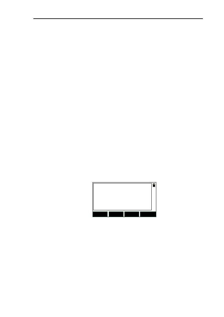
105
After input the file name , pressing [ENT] can create
two new file with same name ;
4) Press [DEL] , then a prompt “Delete?” appears ,and
you can press [ENT] to delete the selected (the opened
file can’t be deleted) or press [ENT] to return back
directly;
5) Press [CLOSE] to cancel the current opened file name ,
the “Opened” displays nothing;
6) Press [ESC] to return to the road menu.
12.2 Horizontal alignment file
This function is to manage the current the horizontal line
date. There are two input methods: element and intersection
In the road menu, press [2] or press [ENT] after moving the
cursor to “HC list” to enter the interface of Horizontal alignment
list, as shown in picture below. If the current file has existed
data, the date will be displayed in the list. The displays about
element method and intersection method are different.
SAVE ADD
DEL. VIEW
12.2.1 Element method
The element method is that using the linear, circular and
curve constitute a road.
1) In the horizontal alignment list interface, press [ADD]
to enter the interface of “Define (H)”, as shown in
picture below (left). In this interface, you can select the
line type, if you select [PT], then you can enter the
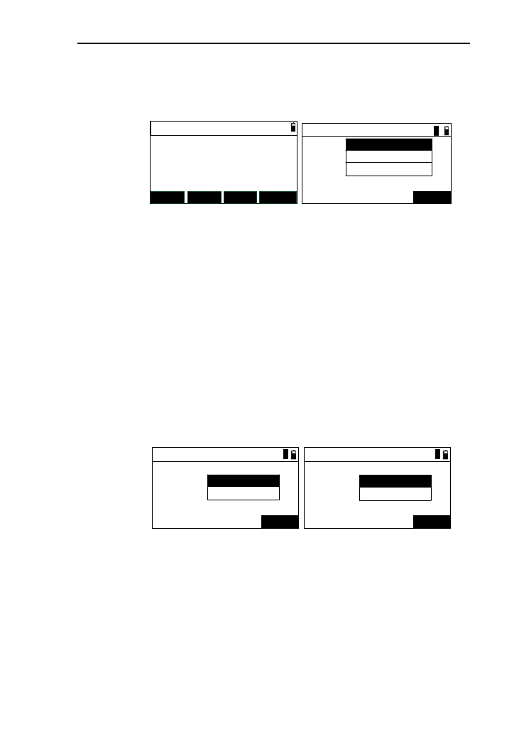
106
interface of the input of intersection method, seen the
chapter 12.2.2. If press the other keys, you can enter
the input of data input;
Define(H)
Pile:
AZ:
STR TRNS
ARC PT
0.000
0°00′00″
Define(H)-Begin
Pile:
N:
ENT
E:
1
[Notice*] Pile: the mileage of the end point of the
current road line.
AZ: the azimuth of the end point of the
current road line.
2) In the case of no road data, press [STR] to enter the
interface of “Define(H)-Begin” ,as shown in
above(right) .After input, press [ENT] to enter the
interface of “Define(H)”;
3) Press [STR] to enter the interface of “Define(H)
-Line” ,as shown below(Left). After input, enter the
interface of “Define (H)”;
Define(H)-Line
AZ:
ENT
Length:
1
Define(H)-Circle
Radius:
ENT
Length:
1
4) Press [ARC] to enter the interface of “Define
(H)-Circle”,as shown above(right). After input, press
[ENT] to enter the interface “Define(H)”;
5) Press [TRNS] to enter the interface of “Define
(H)-Spiral”,as shown above(left). After input, press
[ENT] to enter the interface “Define(H)”;
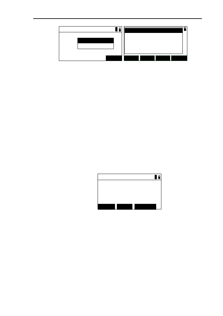
107
Define(H)-Spiral
Radius:
ENT
Length:
1
SAVE ADD
DEL. VIEW
01ST : 0.000
02STR : 0.000
03TRNS : 200.000
04ARC : 500.000
05TRNS : 950.000
6) After input the data, press [ENT] or [ESC] to return to
horizontal alignment list interface, as shown above
(right). The left side of list is line type, and the right
side of the list is mileage. The radius is of the end
point;
7) Press [ADD] to enter the interface of “Define (H)” ,
you can continue to add data;
8) Press [DEL.] to delete the selected data (the start point
can’t be deleted). If press [ESC], return back directly.
9) Press [SAVE] to save the data to the current road file;
10) Press [VIEW] to view the selected data, as shown
below. Here ,as an example of “circle”;
Edit-Circle
Radius: 300.000
400.000
Length:
1
EDIT UP DOWN
① Press [UP] , then display the previous data;
② Press [DOWN], then display the next data;
③ Press [EDIT] to enter the interface of editing the
selected data, the interface and operation is same
as the input data;
④ Press [ESC] to return to the data list.
11) Press [ESC] to save the edit data, then return to road
menu.
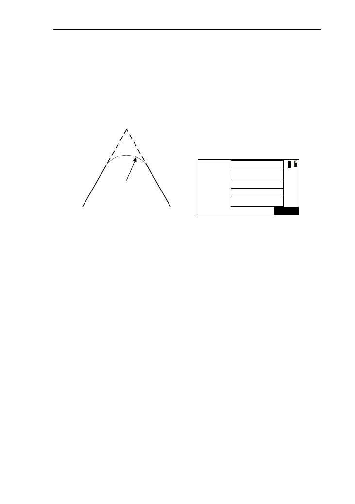
108
12.2.2 The intersection method
The schematic diagram of this method is as shown below
(Left), and the input interface is as shown below (right). The
“Piont PT” is the intersection of road. The “点X” corresponds to
the input intersection number.
Piont PT
Para A2Para A1
Radius R
Next piontFormer point
Radius:
ENT
A1:
N:(Pt1)
E:
A2:
1
The system will not accept negative Para. A1, Para. A2 nor
Radius. If inputting the radius, the system will insert a arc with
defined radius in between the former point and the next point. If
inputting parameters A1 and A2 of the spiral, the system will
insert defined spiral in between the line and the arc.
[Notes*]: When inputting A1 and A2 according to the length
L1 and L2 of the spiral, the formula to calculate A1
and A2 are as followed:
A1=√(L1·Radius)
A2=√(L2·Radius)
1) In the horizontal alignment list interface , press [ADD]
to enter the interface of “Define(H)” , then press [PT] ,
if there are no alignment data , enter the interface of
“Define(H)-Begin” to input the start point, specific
operation seeing “element method” ;
2) After input the start point data ,press [ENT] to enter the
interface of the input of intersection, as shown above
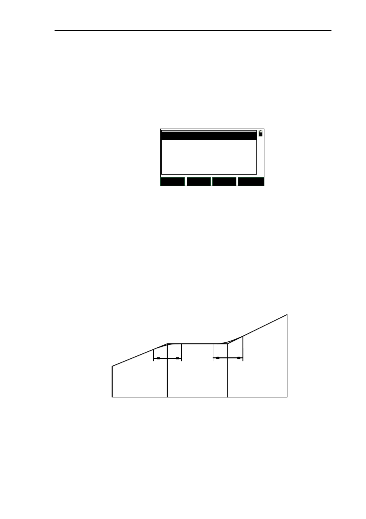
109
(right);
3) Each intersection has been input, pressing [ENT] will
enter the interface of the input of the next intersection.
If the input is completed, press [ESC] to enter the
interface of data list,as shown below, the left is line
type, and the right is northing coordinate data;
SAVE ADD
DEL. VIEW
01ST : 0.000
02PT : 2568.784
03PT : 3659.254
4) The other operations are same as them of element
method.
12.3 vertical alignment
The vertical alignment consists of a set of intersection
points, which contain pile, elevation and curve length. The curve
length of the start point and end point are must be zero. The
number of intersection is no more than 20.
Stake 0 508.306 1000.48
elevation 324.325 329.247 325.689
Length 0 84.56 52.806
1) In the road menu. Press [3] or press [ENT] after
moving the cursor to “VC list” to enter the interface of
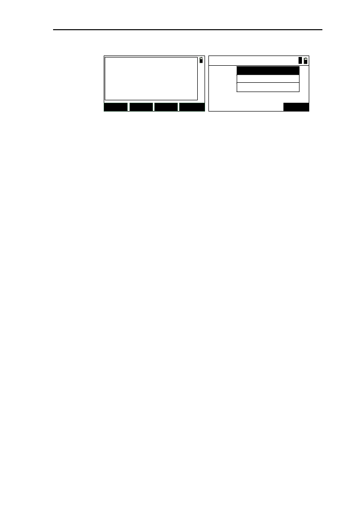
110
vertical alignment list, as shown below (left);
SAVE ADD
DEL. VIEW
Define(V)-Begin
Pile:
Elv.:
ENT
Length:
1
2) If there is no vertical alignment data, press [ADD] to
enter the interface of “Define (V)-Begin”. After the
input, press [ENT] to continue inputting the vertical
alignment data, and the title of the interface is changed
“Define (V)-XX”. Among them, the “XX” is the line
number ;
3) After input all data, press [ESC] to return to the vertical
alignment list, as shown below, the left is line type and
the right is pile;
4) The other operations are same as them of element
method.
12.4 Staking out Roadway
In this function, the linear files input will be used. You can
select the file you at any moment, so, the staking out of any
mileage can be accomplished. You won’t worry about whether
the limited linear data of alignment file is enough because of this
design. You can divide any road into a few small linear files to
story.
The terms of staking out roadway:
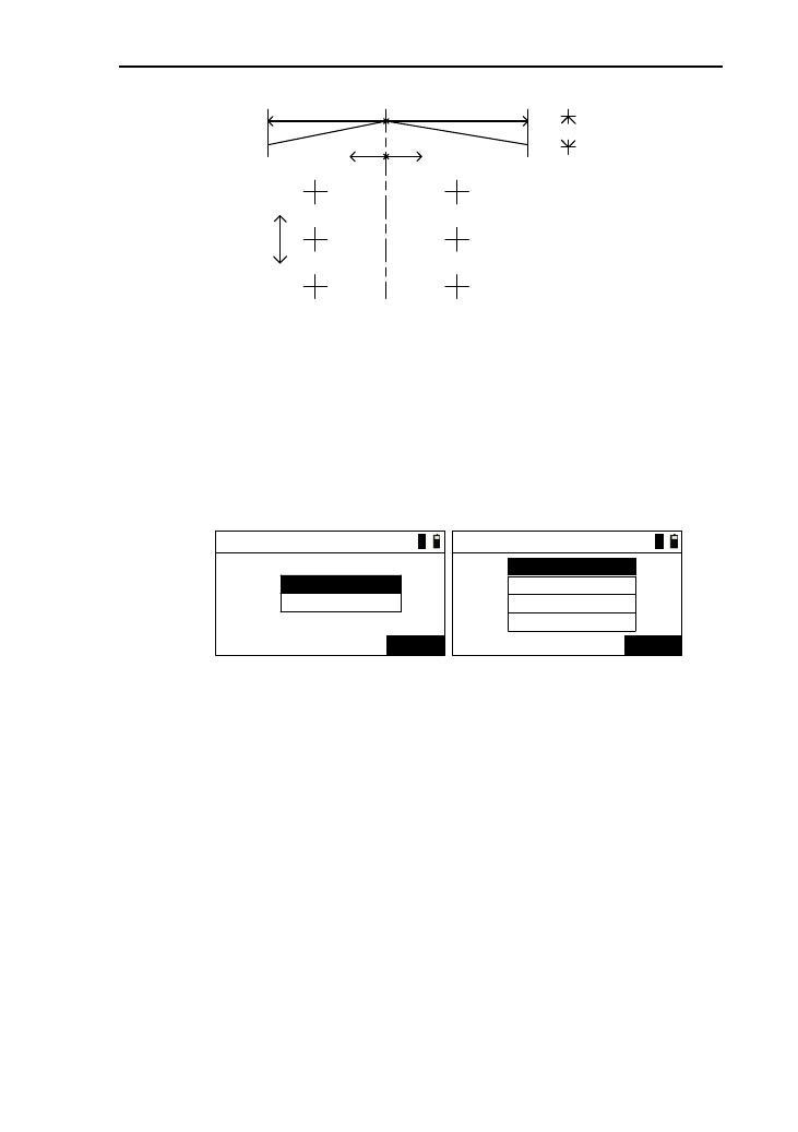
111
Left deviation Right deviation
520 Mileage
510
530
Mileage increment
Altitude difference(-)
Midcourt line
Midcourt line
Left deviation Right deviation
1) Before you stake out roadway, please confirm whether
you have been stationed, if not, you should enter the
station interface to station;
2) In the road menu, press [4] or press [ENT] after moving
the cursor to “S-O road” to enter the interface
“Parameter 1/2” ,as show below(left);
Parameter 1/2
Start:
ENT
Space:
1
Parameter 2/2
ENT
1
L-dist:
R-dist:
L-dV :
R-dV :
3) After the input, press [ENT] to enter the interface of
“Parameter 2/2” ,as shown in picture above(right);
[Notice*]:
L(R)-dist: left/ right deviation;
L(R)-dv: left/ right altitude difference.
4) After the input, press [ENT] to enter the interface of
“Roadway-Center” with the first pile point displayed, as
shown in picture above;
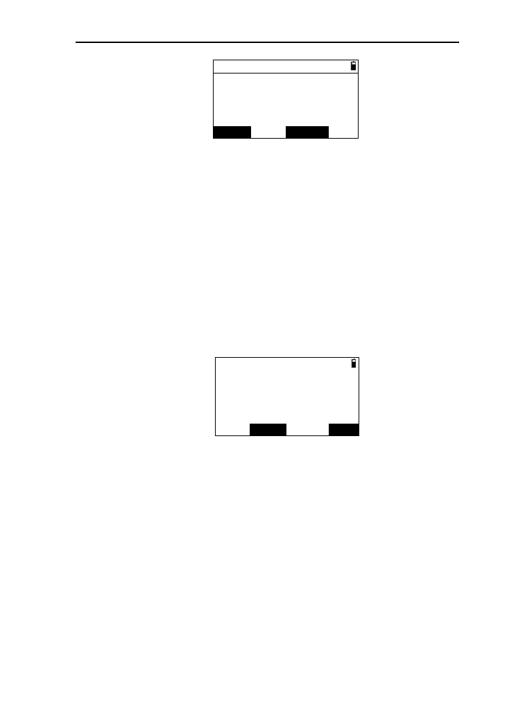
112
Roadway-Center
Pile:
CALC
Offset:
VD:
T.H:
EDIT
0.000
0.000
0.000
0.000
5) Pressing [▼] can increase the pile according to the
space. Pressing [▲] can decrease pile;
6) Pressing [◄]can switch to the interface of left pile data,
and pressing [►] can switch to the interface of right
pile data;
7) Press [EDIT] to enter the interface of the edit of current
pile point, and you can edit pile, offset, elevation (HV),
etc;
8) Press [CALE] to enter the display interface of
coordinates of the current pile point;
Code:
S-O
N:
E:
Z:
REC.
Pt.N: code
13.893
14.387
1.269
K+20.0
9) Press [REC.] to enter the interface of recording data,
and you can record the calculated data;
10) Press [S-O] to enter the interface of staking out, specific
operation seen the chapter 7.6;
11) Press [ESC] to return to “Roadway-XX”,and you can
stake out after calculate coordinates of the set pile.

113
13. Adjustments and Corrections
The instrument is under strict test and calibration, the
quality is accord with the standard demand. But after a
long-distance transportation and environment change, the small
change of instrument parameter is inevitable. Therefore, the new
purchased instruments should be checked and calibrated before
surveying to ensure the precision.
13.1 Tubular Level
Check
See reference in using tubular level to level the instrument
precisely.
Calibration
1. In the calibration, if the level bubble diverges from the
center, use the foot spiral which parallels the leveling tube to
adjust to make the bubble move half of the distance to the center.
For the remaining, use the calibration needle to turn the level
calibration screw (in the right of the water-level) to adjust the
bubble to the center;
2. Turn the instrument 180° to check that whether the
bubble is in the center. If the bubble is not centered, repeat step 1
until the bubble is in center;
3. Turn the instrument 90° and use the third foot screw to
adjust the bubble to the center;
4. Repeat the steps of checkout and calibration until the
bubble in the center in every direction.
13.2 Circular Level
Check
After the level tube is calibrated correct, if the circular level

114
bubble also in center, so there is no need to calibrate.
Calibration
If the bubbles is not in the center, use the correction needle
or six angle wrench to adjust the correction screw which under
the bubble to make the bubble to the center. For calibration, you
shall first loosen the calibration screw (1 or 2) which opposite to
the direction of the bubble offset, then tighten the other
correction screw in the offset direction to make the bubble in the
center. When the bubble is in center, make sure the fastening
force of the
Three calibration screws are consistent.
13.3 Reticle of the telescope
Check
1. Aim at a target A from the telescope after leveling the
instrument the cross wire on the reticle. Lock the instrument
with vertical and horizontal locking knob after aiming at A.
2. Rotate the vertical slow motion knob, move A point to
the edge of the field of view (A 'points);
If point “A” moves along the vertical line of the crosshair,
but is still in the vertical line as the left picture, the crosshair
doesn't need to calibrate. If point “A”deviate from vertical line
center, as the right picture, the crosshair is slant, so need to
calibrate the reticle;
8
8
A
A′
8
8
A
A′
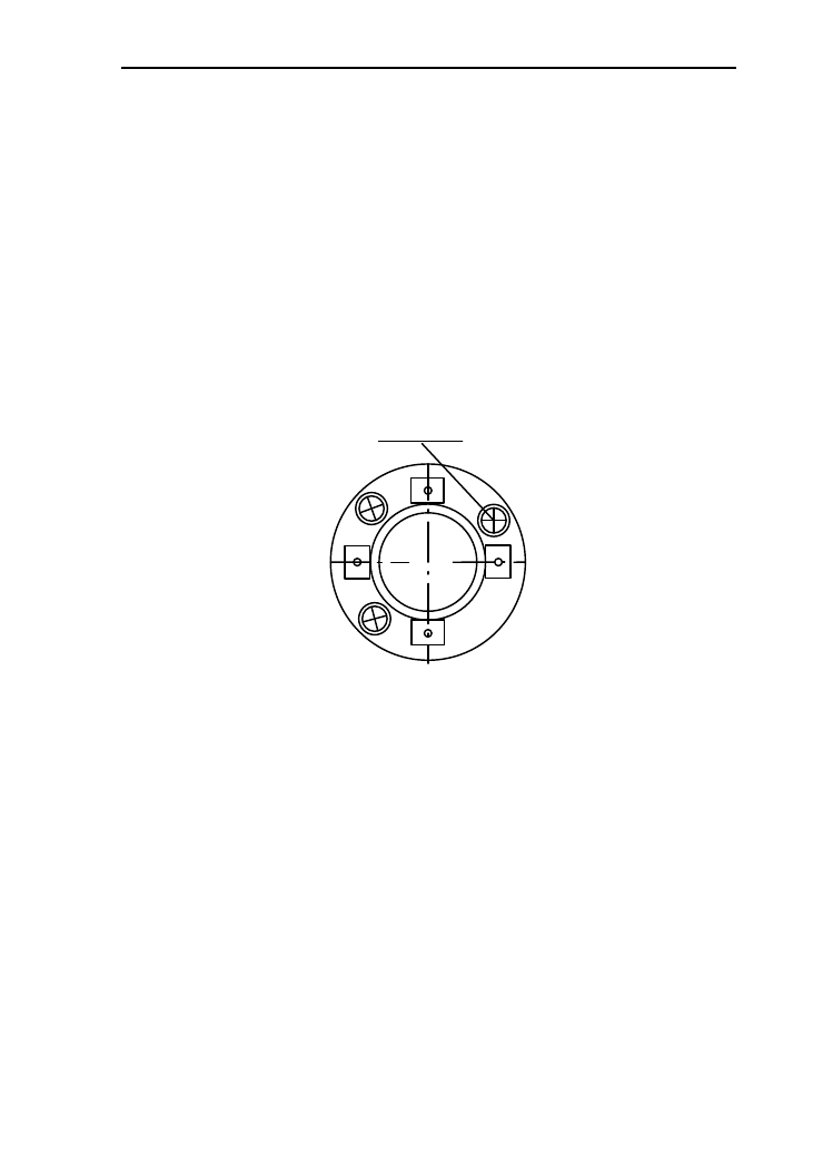
115
Calibration
1. First, take down the reticle cover between telescope
eyepiece and focusing hand-wheel, and you can see four fixed
screw of the reticle bed (sees attached figure);
2. Unscrew the three fixed screw evenly with screwdriver,
rotate the reticle around collimation axis, to make A point on the
vertical line of the reticle;
3. Tighten the screw evenly, test the calibration results with
the above methods;
4. Cover the reticle.
Fixing screw
Eyepiece
13.4 The Perpendicularity of Collimation axis and
Cross axis (2C)
Check
1. Set a target A in about 100m away, and make sure the
vertical angle of the target is within ±3°.Precisely level the
instrument and switch on it;
2. Make the telescope focused on target A in face left, and
read the horizontal angle e.g. HA (L)=10°13′10″;
3. Loosen the vertical and horizontal brake hand-wheel,
turn the telescope, rotate the alidade to face right and focus on
the same target A. Before aiming please tighten the horizontal
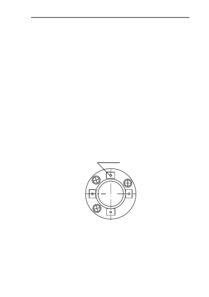
116
and vertical brake hand-wheel and read the horizontal angle;
e.g. HA (R)=190°13′40″
4. If 2C=L-(R±180°)=-30″≥±20″, the instrument need to be
calibrated.
Calibration
1.Use the horizontal slow motion knob to adjust the
horizontal angle to the right reading which has eliminated the C.
R + C = 190°13 '40 "-15 "= 190°13' 25";
2.Take down the reticle bed cover between the telescope
eyepiece and focusing hand-wheel, adjust the calibration screw
of the crosshair on the left and right. First, loosen the screw on
one side, and screw up the screw on the other side, move the
reticle and focus on target A;
3. Repeat the test steps, calibrate it to | 2 C | < 10;
4. Tighten the calibration screws, put the protective cover
back.
Cross wire correction screw
Eyepiece
Note: Check the photoelectric coaxiality after calibrating.
13.5 Vertical plate index zero automatic
compensation

117
Checkout
1. After Setting up and leveling the instrument, make the
direction of the telescope consistent with the line between the
center of the instrument and any of the foot screw;
2. The vertical plate index change to zero after switching on
Tighten the vertical brake hand-wheel and the instrument display
the current telescope vertical Angle;
3. Screw the leveling screw towards one direction for
circumferential distance around 10mm, the vertical angle
displayed will disappear through the process and ‘Tilt over!’
appears to the column. It indicates that the inclination of the
instrument is over 3′, which is over the range the instrument was
designed to compensate. Screw the leveling screw back towards
the opposite direction, the vertical angle re-appears on the screen.
It shows that the tilt works well now. Users may observe the
change of the readout about the critical point.
Slowly rotate feet X to 10 mm around in one direction, the
display of the vertical angle will change from changing until
disappear to appear "Tilt over!" correspondingly , it indicate that
the dip Angle of the vertical axis is bigger than 3 ', beyond the
range of vertical plate compensator design . When rotating the
feet spiral recovery in the opposite direction, the instrument
shows vertical Angle again, if you can see the change when
testing it again and again in critical positions, it says that vertical
plate compensator works normally.
Calibration
When finding the tilt compensator abnormal, please send
the instrument back to factories for checking.

118
13.6 Vertical index error (angle i) and set vertical
index 0
Please first adjust finely the reticule of the telescope and the
compensator before calibrating and checking index error.
Check
1. Turn on the instrument after placing and leveling it, and
focus the telescope on a clear goals .A to get the face left reading
of vertical Angle L;
2. Turn the telescope around and aim at the same target A
and get the face right reading of vertical Angle R;
3. Assume that the zenith of the vertical angle is 0°, then
angle i= (L+R-180°)/2 or Angle i= (L+R-540°)/2;
4. If | i |≥10", may be you need reset the zero value of
vertical index;
5. For the following steps, see reference in chapter 11.6.1.
Note: Repeat the checkout steps to retest the index error
again (i Angle). If the index error still cannot accordance with
requirements , it should check the three steps of calibration index
zero setting (in the course of zero setting ,the vertical angle
showed is not compensated and corrected, it is just for reference)
to see whether it is incorrect, whether the focusing of target is
correct, reset according to the requirements;
6. If the index error does not meet requirements at all, you
may have to send the instrument back to factories for checking.
13.7 Centering device
Check
Place the instrument onto the tripod and draw a cross on a
white paper, place the paper with a cross on the ground right
below the instrument;
2. Adjust the focal length of the optical plummet (for the
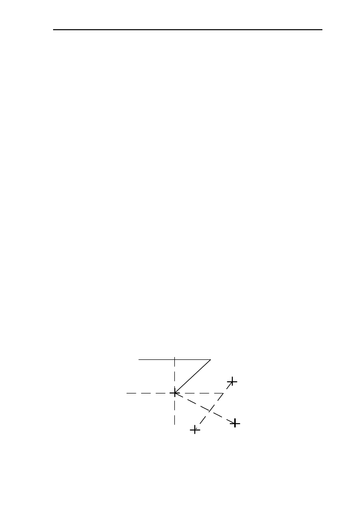
119
optical plummet) or press key[★] to switch on laser plummet,
move the white paper to make the cross in the center in the field
of view (or laser flare);
3. Turn the feet screw, make the center mark of the
plummet coincide with the cross center;
4. Rotate alidade, every turn of 90°, observe the contact
ratio of the optical plummet and cross center;
5. When rotate the alidade, the center of the optical
plummet always coincide with the cross center, there is no need
to calibrate. Otherwise you should calibrate as the following
methods.
Calibration
1. Take down the screw cover between the optical plummet
eyepiece and the focusing hand-wheel;
2. Fix the white paper with a cross, and mark the points
when the instrument rotates 90°, as the figure shows A, B, C, D
points;
3. Connect the diagonal points A、C and B、D with a straight
line, the intersection name of the two line is point O;
4. Use the calibration needle to adjust the four calibration
screw, to make the center mark of the plummet coincide with
point O;
Cross center on the ground
A
C
B
0

120
5. Repeat step 4, check and calibrate until it meet the
requirements;
6. With the laser plummet, unbolt the laser cover, using 1 # hex
wrench to adjust the three screws, fasten one side and loosen the
other side, and adjust the laser flare to point O;
7. Put the cover back in place.
13.8 Addictive constant (K)
The instrument constant is inspected when it out, and
correct it inside the machine, make K = 0. Instrument constant
change rarely, but we suggest that check it this way for one or
two times each year. The checkout should be done in the
standard baseline, or you can take the following simple method.
Checkout
1. Choose a flat field A to set up and level the instrument ,
mark three points A、B、C in the same line ,their interval is 50m,
and set up the reflection prism accurately;
2. After setting the temperature and atmospheric pressure of
the instrument, measure the horizontal distance of ‘A B’ and
‘ AC’ accurately;
3. Place the instrument at point B then centering it
accurately to measure the horizontal distance of BC precisely;
4. Obtain the distance measurement constant of the
instrument: K= AC-(AB+BC);
K should be close to zero, if | K | > 5 mm,it should be send
to standard baseline field for strict checking. You can calibrate it
based on the checking value.
Calibration
If it turns out the instrument constant does not close to 0 but
changing after strict inspection, you need to calibrate it,and set
the instrument additive constant according to the comprehensive

121
constant K value. Such as: the K has been measured as ‘-5’
according to the method above, and the original instrument
constant is ‘-20’, so the new value should be set as ‘-20-(5)
=-15’; Input ‘-15’ through "menu-> 6->2" and then confirm.
Use the vertical line of the reticle to orientate, make A, B
and C at the same line accurately. There must be a clear mark for
point B on the ground to focus.
Whether the prism center of the point B coincide with the
instrument center is the guarantee of checking the accuracy, so,
you have better use tripod and all-purpose tribrach, for example,
if you change the three-jaw type prism connector with tribrach,
keep the tripod and tribrach stable, just change the prism and the
part above the tribrach of instrument, and it can reduce the error
of misalignment
13.9 The parallelism of collimation axis and
photoelectricity axis
Checkout
1. Place a reflector prism 50 meters away from the
instrument;
2. Focus on the reflecting prism center with telescope
crosshair accurately;
3. Check whether the telescope crosshair center coincide
with the emission photoelectricity axis center, if they coincide on
the whole we can say it qualified;
Calibration
If the telescope crosshair center deviates from emission
photoelectricity axis center largely, send it to professional repair
and calibration department.

122
13.10 Non-prism ranging
The red laser beam is coaxial with the telescope, used for
no prism ranging, and it is sent by telescope. If the instrument
has been calibrated, red laser beams will coincide with the line
of sight. The external influence such as the vibration, the larger
temperature change and other factors may make laser beam and
viewing not overlap.
Before precise ranging, you should check whether the
direction of the laser beam is coaxial. Otherwise, it could lead to
inaccuracy.
Warning:
Looking straightly at the laser is dangerous.
Prevention:
Don't look laser beams directly, or focus on others.
Checkout:
Put the gray side of the reflector towards the instrument,
and put it 5 meters and 20 meters away. Start laser direction
function. Focus on the reflector center by the telescope crosshair
center, and check the position of the red laser point. Generally
speaking, the telescope is equipped with special filter, human
eyes can′t see laser point through the telescope, you can see the
offset between the red laser point and the reflector crosshair
center, you can observe this above the telescope or at the side
face of reflector. If laser center coincide with the crosshair center,
it indicates that the adjustment meet required accuracy. If the
offset between the point position and the mark of crosshair is out
of limit, it will need to be sent to professional department for
adjustment.
If the reflector is too bright under the illumination of laser
beams, the grey side can be replaced by the white side.
123
14. Technical parameters
Serial
HTS-360R
Angle measurement (Hz, V)
Method
Absolute encoder
Reading head
Diameter
Accuracy
2″
Telescope
Image
Positive
Magnification
30x
Field of view
1°30′
Min. target distance
1.2m
Resolution
4″
The tube length
130mm
C
ompensator
System
Photoelectric integrated dual
axis compensator
Working range
±3′
Distance measurement (IR)
Ranging
Non-prism mode1
600m
Single prism mode
3000m
Time for a
measurement
Precision
0.8s
Tracking
0.3s
Standard
deviation
Non-prism mode
±(3+2ppm×D)mm
Prism mode
±(2+2ppm×D)mm
Mini. readout
1mm
Communication
Internal data storage
20000 pionts (Standard
equipped 8G Udisk)
Port
Standard RS232 serial port;
124
Bluetooth;USB;Mini-USB port
Operation
Display
3.2 -inch , 192*96 pixels
highlight LED display,3 class,
adjustable brightness
Keyboard
Numeric keyboard
Laser plummet
Type
Laser point, brightness
adjustable in steps,4 class
Accuracy
1 mm (1.5m instrument
height)
Environmental conditions
Temperature range (operation)
-20℃~﹢50℃
Temperature range (storage)
-25℃~﹢70℃
Splash and dust proof (IEC 60529)
IP66
Weight
Weight of instrument without
(battery)
3.7kg
Weight of instrument box
2kg
Power supply
Battery type
BT 30 High energy Lithium
battery
Voltage / Capacity
7.4V/ 3400mAh
Working duration
16 hours (Under 25 ℃ with a
new battery, measuring once for
every thirty seconds)
Number of measurements
Approx. 12 000
1:Refer to the conditions of good weather and the goal of
KODAK CAT NO.E1527795 (90% of reflecting surface)
The provision of the indicators with reference to the

125
enterprise standard Q / 320507 ATS HGR01-2010 type total
station"

126
Appendix A File format introduction
(Sunway)
These following examples to instruct exported file format
STA ST001,1.205,AD
XYZ 100.000,100.000,10.000
BKB BS001,45.2526,50.0000
BS BS001,1.800
HVD 98.2354,90.2314,10.235
SC A1,1.800,CODE1
NEZ 104.662,99.567,10.214
SD A2,1.800,CODE1
HVD 78.3628,92.4612,4.751
SA A3,1.800,CODE1
HV 63.2349,89.2547
NOTE this note
Every record consists of two lines:
The information of first line: record type, name, elevation,
code
Such as:
STA refers to station point
BKB refers to back sight Angle data
BS refers to back sight
SC refers to coordinate data
SD refers to distance measurement data
SA refers to Angle measurement data
The second line information: data types, data records
Such as:
NEZ refers that the following data are coordinates with
the order “NEZ”

127
ENZ refers that the following data are coordinates with
the order “ENZ”
HVD refers that the following data are horizontal Angle
and vertical Angle and slope distance
HV refers that the following data are horizontal Angle
and vertical Angle