Hi Target Surveying Instrument ZHDA10 GNSS RTK User Manual SL600 GNSS RTK Manual
Hi-Target Surveying Instrument Co., Ltd GNSS RTK SL600 GNSS RTK Manual
User manual-revised
A10 GNSS RTK Manual
Manual Revision
Revis ion
Date
Revision
Level
Description
Apr.2014 1 A10 GNSS RTK Manual1.0
GEOSOLUTION I GOTEBORG AB
All Rights Reserved
1

Content
Preface ........................................................................................................ 4
1. Instruction ..................................................................................... 5
2. Your Suggestions ......................................................................... 5
Summary .................................................................................................... 6
1. Introduction ................................................................................... 7
2. Product Features ........................................................................... 7
3. Usage and Notes ........................................................................... 8
Receiver Introduction ............................................................................. 10
1. Introduction ................................................................................. 11
2. Receiver Appearance.................................................................. 11
3. Control Panel .............................................................................. 11
4. Upper Cover ................................................................................ 12
5. Lower Cover ............................................................................... 13
6. Battery ......................................................................................... 14
7. Environmental Requirement ..................................................... 15
8. Electrical Interference ................................................................ 15
General Operations ................................................................................. 17
1. Introduction ................................................................................. 18
2. Button functions ......................................................................... 19
3. Led Status Instructions............................................................... 21
4. Static Data Storage ..................................................................... 22
5. RTK Data Storage ...................................................................... 23
6. Self-inspect and reset Receiver ................................................. 23
7. Format Receiver ......................................................................... 23
8. Power Supply System ................................................................ 24
Technical Parameters .............................................................................. 27
1. Introduction ................................................................................. 28
2. Receiver ....................................................................................... 28
3. Ports ............................................................................................. 29
4. Function Key and LED .............................................................. 29
2

5. Intelligent Voice Module ........................................................... 29
6. Accuracy ...................................................................................... 29
7. Physical Feature.......................................................................... 30
8. Environment................................................................................ 30
3

Preface
■ Instruction
■ Your Suggestions
C
H
A
P
T
E
R
1
4

1. Instruction
Welcome to A10 Series GNSS RTK system manual. This manual is
designed for A10 GNSS RTK system, and use A10 GNSS RTK as an
example to explain the installation, setup, and usage of the GNSS RTK
system.
If you have used other GNSS RTK system before, we suggests you
read this manual carefully and this manual will help you to understand our
A10 GNSS RTK system easily.
2. Your Suggestions
If you have any suggestions or comments on the manual, please feel
free to contact us, it will help us to improve our manual quality greatly.
5

Summary
■ Introduction
■ Products Features
■ Usage and Notes
C
H
A
P
T
E
R
2
6
1. Introduction
A10 GNSS RTK system adopts modularized design, so as to enable
users to change into different differential transmission modules according
to various requirements. Meanwhile the designed self-diagnosis function
can automatically check the working status of all hardware and software of
the A10 receiver while working, and arouse the problem part by its
intelligent voice messenger in case of some problem.
Data collection controller can be connected with receiver mainframe
via Bluetooth or cable; built-in high-capacity battery is suitable for
long-time field work; static data can be stored in the built-in memory card
of receiver and downloaded via USB port to your PC.
Tips: 1. A10 GNSS RTK system has many modules. This
manual does not represent standard configuration.
Users need to notify their own requirements for the
different configuration due to different applications.
2. And before using, we suggest users firstly to check
whether the package box is damaged, and then open
careful and check whether inner items matched with
the order list of their own. If there are some missing
or damaging cases exist for products and accessories,
please contact with the local distributor Immediately.
3. Last but not least, please carefully read manual
before carrying, handling and using!
2. Product Features
1. BD970 mother board of Pacific Crest, a Trimble Company,
multi-satellite, multi-system kernel.
7
2. 1+X multi-module communication units.
3. PCC Radio module (optional) compatible with Trimble/Leica RTK.
4. Double battery capacity as 5000mAh, 12 hours for RTK
operating.
5. The highest performance in waterproof, dustproof and
anti-drop.
6. Adjustable to be single GNSS system or multi-GNSS system: GPS,
GLONASS, GALILEO.
3. Usage and Notes
Although A10 receiver using chemical and impact resistance material,
but necessary taking care and maintenance is still required for such a
precise instrument.
Warning: The receiver must be used and stored in the
specified temperature.
To ensure the quality of continuous tracking satellites and signals,
surveying work should be in open air, while there should no any obstacle
in space above 15° altitude angle; in order to reduce all kinds of electrical
interference to the GNSS satellite signals. Besides, there should not be
strong electrical interference around within about 200m range, such as the
television tower, microwave stations, high voltage transmission line. Also,
in order to avoid or reduce the occurrence of multi-path effect, stations
should be away from terrain or geographical objects, which will strong
effect electrical signal, such as high-rise buildings, big pool, etc.
Changes or modifications not expressly approved by the party
responsible for compliance could void the user’s authority to operate the
equipment.
8

This equipment has been tested and found to comply with the limits
for a Class B digital device, pursuant to Part 15 of the FCC Rules. These
limits are designed to provide reasonable protection against harmful
interference in a residential installation. This equipment generates, uses
and can radiate radio frequency energy and, if not installed and used in
accordance with the instructions, may cause harmful interference to radio
communications. However, there is no guarantee that interference will not
occur in a particular installation.
If this equipment does cause harmful interference to radio or
television reception, which can be determined by turning the equipment
off and on, the user is encouraged to try to correct the interference by one
or more of the following measures:
-- Reorient or relocate the receiving antenna.
-- Increase the separation between the equipment and receiver.
-- Connect the equipment into an outlet on a circuit different from that to
which the receiver is connected.
-- Consult the dealer or an experienced radio/TV technician for help.
The device must be operated to provide a separation distance of at
least 20cm from User.
9

Receiver Introduction
■ Introduction
■ Receiver Appearance
■ Control Panel
■ Upper Cover
■ Lower Cover
■ Battery
■ Environmental Requirement
■ Electric Interference
C
H
A
P
T
E
R
3
10
1. Introduction
This Chapter mainly introduces A10 receiver appearance, buttons and
indicator led and so on.
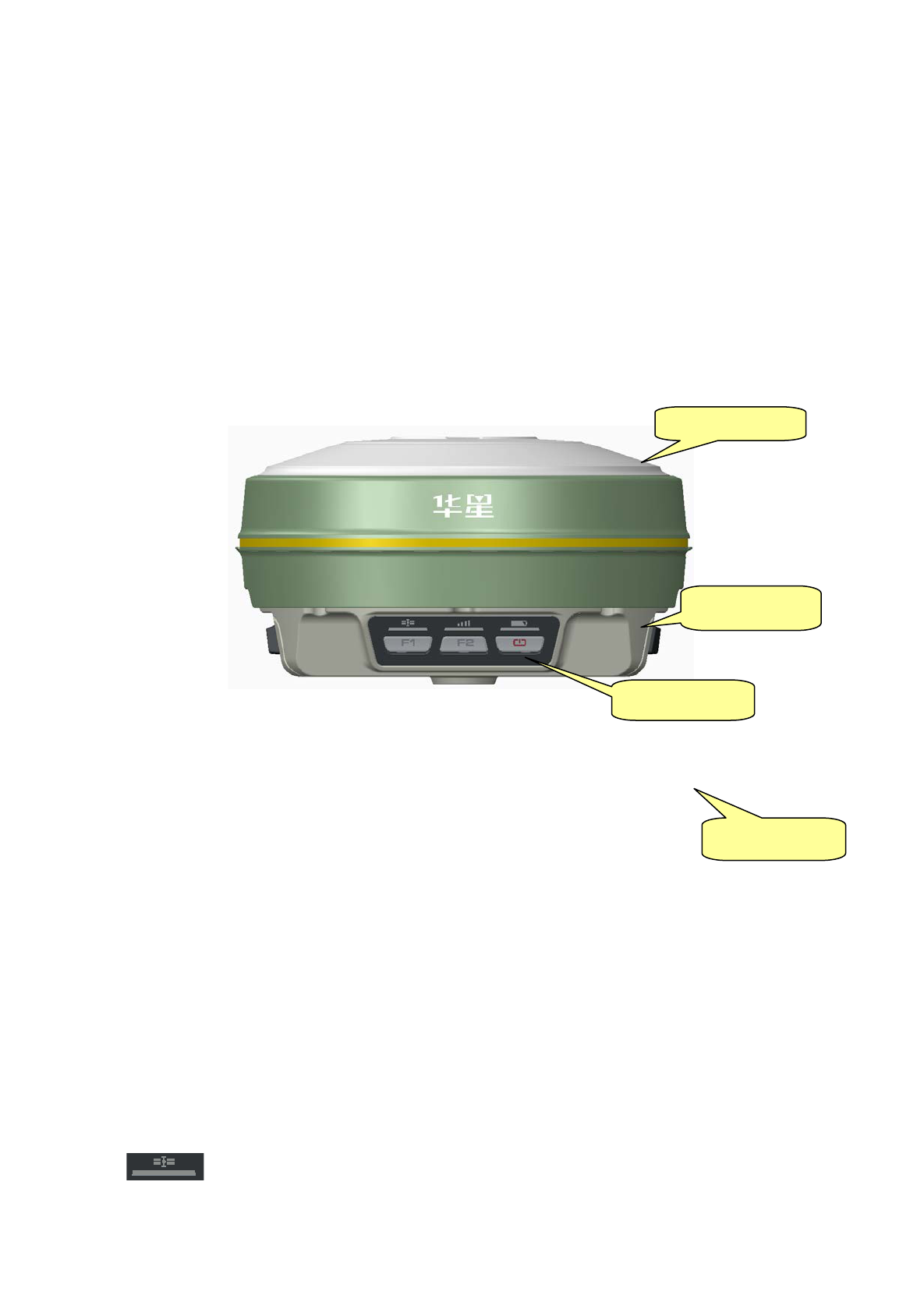
2. Receiver Appearance
Receiver Appearance mainly including 4 parts: upper cover, lower
cover, guard collar and control panel, as Figure 3-1
Figure 3-1 Receiver Appearance
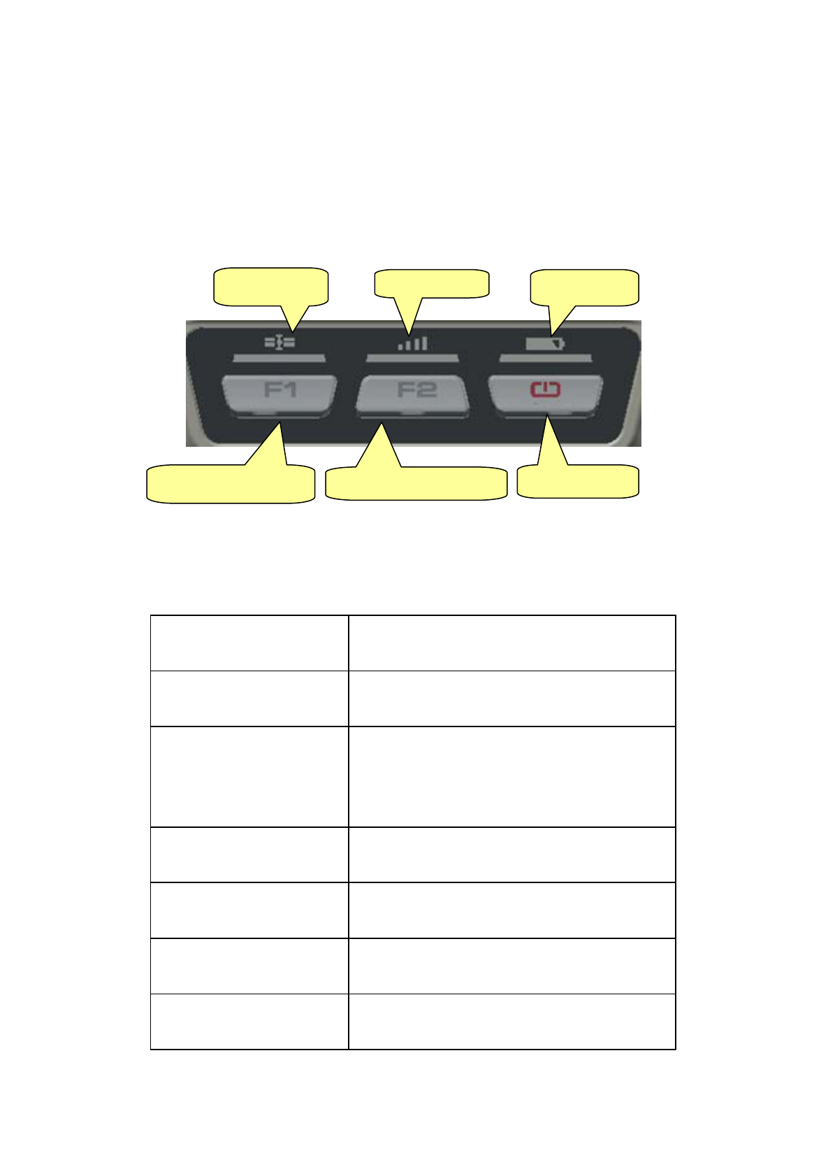
3. Control Panel
Figure 3-1, in the middle of red frame of A10 receiver is control panel.
And the control panel contains the F1 key (function key 1), F2 key
(function key 2) and the power button, 3 indicator leds which are
respectively satellite led, the status led (dual-color led ), the power led
(dual-color led). The simple three buttons include all the features setting of
the A10 receiver.
Satellite led(green led)
Control Panel
Upper Cover
Guard Collar
Lower Cover
11
Status led(red-green dual-color led)
Power led(red-green dual-color led)
Function Key: settings of working mode,satellite elevation
angle,automatically base setting, reset receiver and so on.
Function Key: settings of data link, collection interval, back to
original setting.
Power Key: setting confirmation, automatically base setting and
so on.
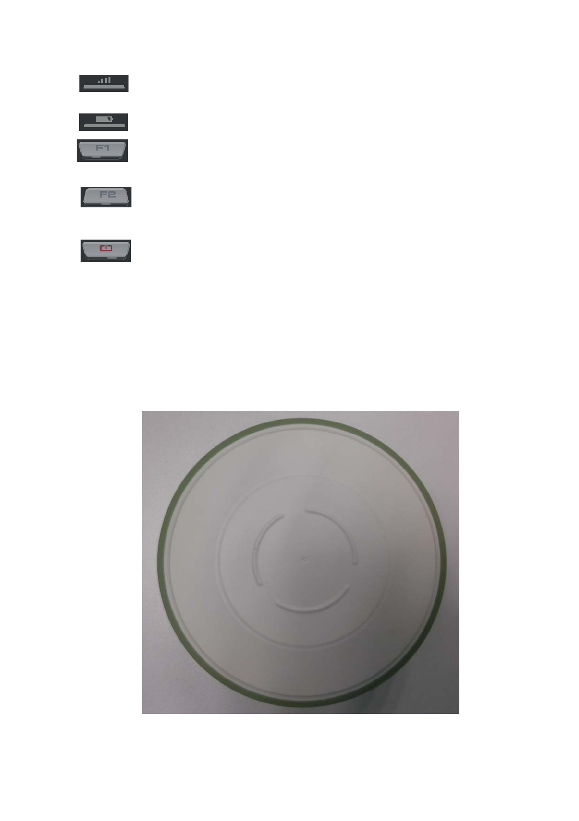
4. Upper Cover
Figure 3-2 indicates the upper cover of A10 receiver, the main
function of which is anti-drop and anti-scratch.
Figure 3-2 Upper Cover
12
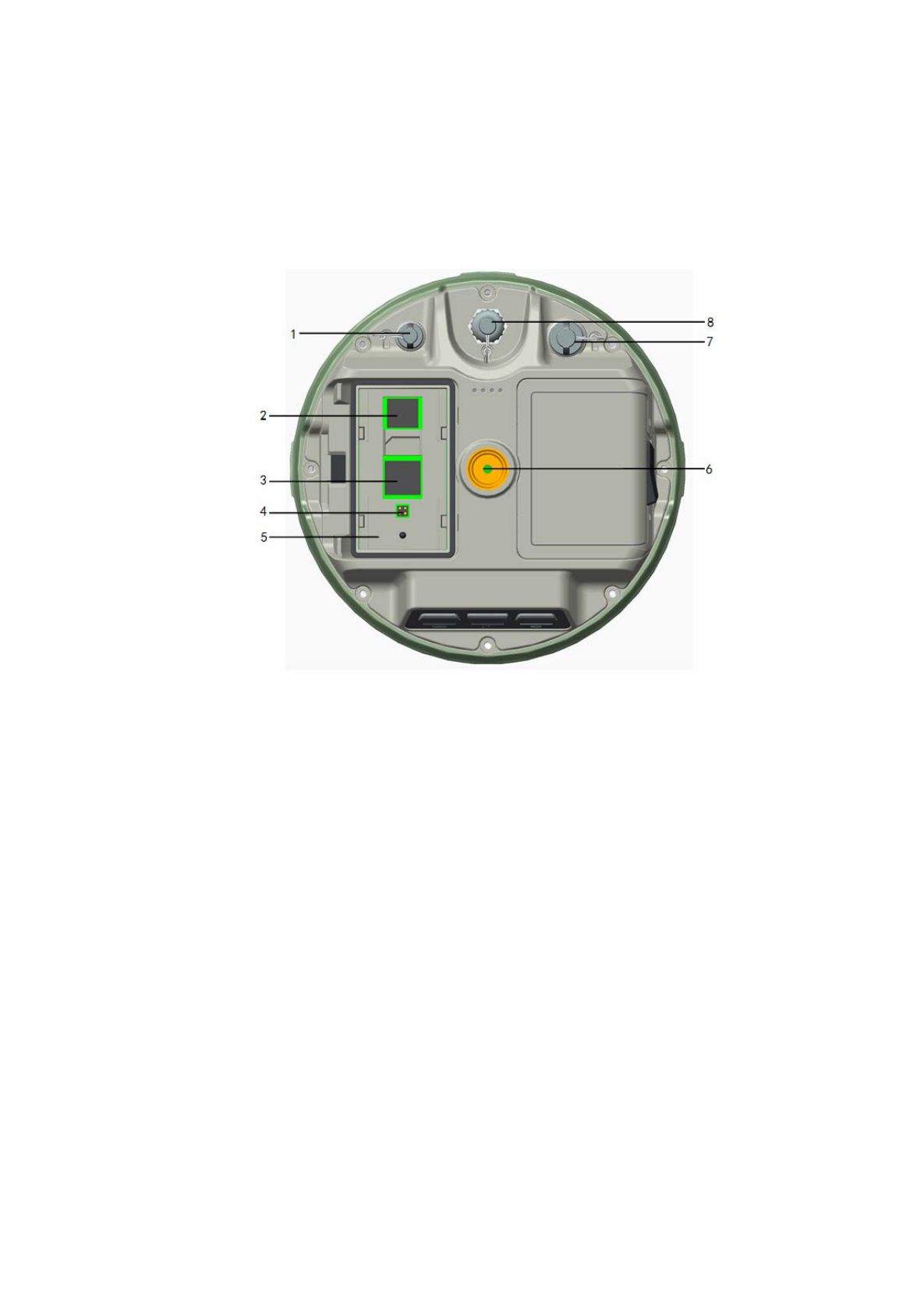
5. Lower Cover
As figure 3-3, lower cover of A10 includes communication module
slot, battery groove, five-pin port, eight-pin port, loudspeaker and so on.
1-Five-pin Port and Protection Plug
2-SD Card Slot
3- SIM Card Slo t
4-SLC Power Supply Block
5-Battery Groove
6-Joint Nut
7-Eight-pin Port and Protection Plug
Figure 3-3 Lower Cover
Communication module connector: connect communication module
and mainframe
Battery Groove: install 5000mAh lithium battery
Five-pin port: connect mainframe with external data link or with
13
external power supply
Eight-pin Port: connect A10 receiver with computer, or controller for
data download and delete
Protection Plug: anti-dust and waterproof for socket.
SIM card slot: when choose GSM communication, install SIM card.
SD Card Slot: install SD card to save large volume data.
Joint Nut: fix instrument with tribrach and centering pole.
Loudspeaker: voice broadcast for real-time operation and status.
Tips: 1. if no need to use five-pin port, eight-pin
port and differential antenna port, please
affix rubber plugs to achieve waterproof
and dustproof.
2. when water comes in loudspeaker, maybe
it becomes silent or sound hoarse. But
it will be back to normal after drying.
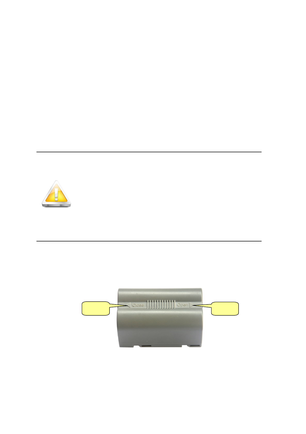
6. Battery
As figure 3-4, the appearance of 5000mAh lithium Battery
Figure 3-4 Battery Front
Close
Open
14
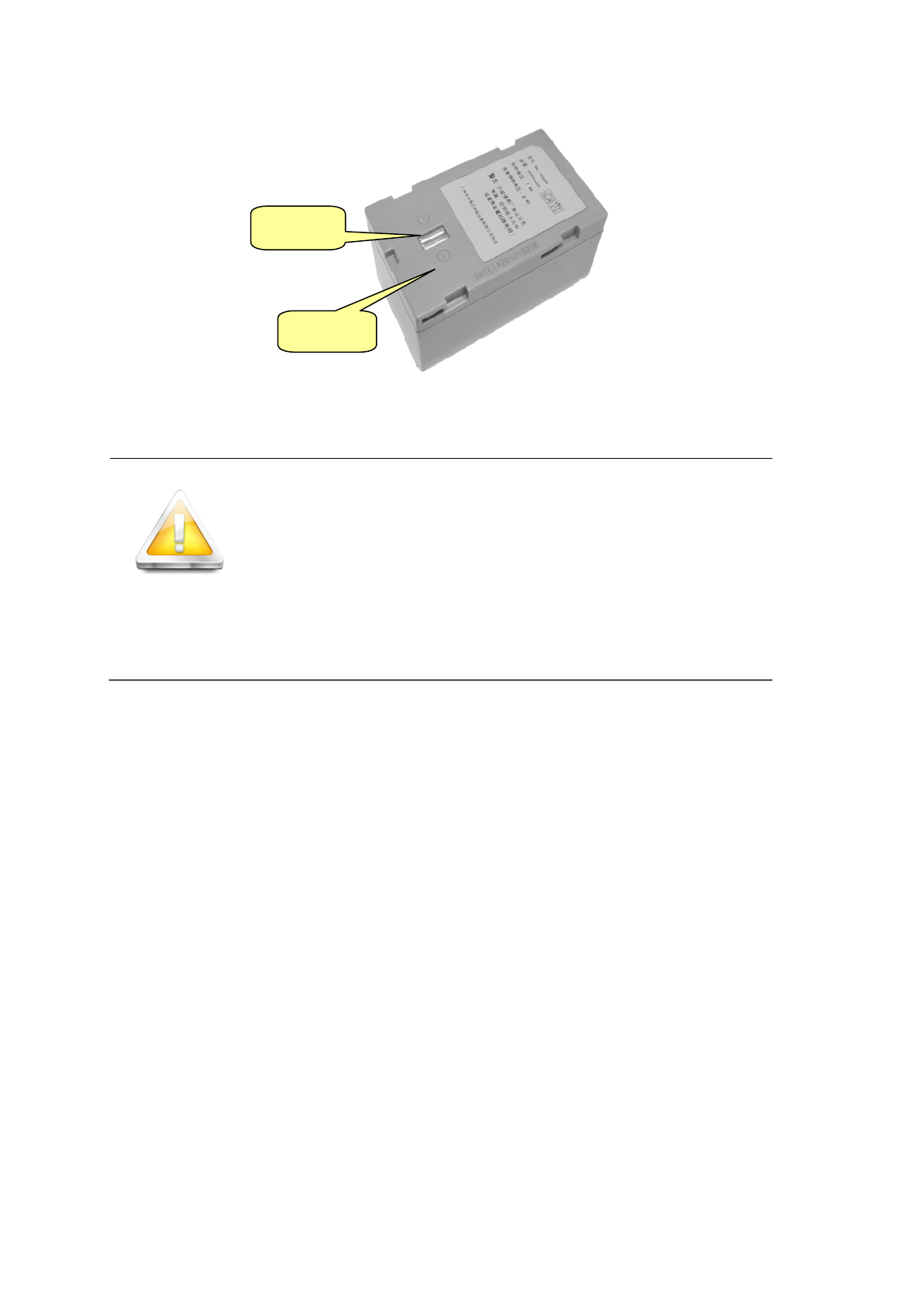
Figure 3-5 Battery Back
CAUTION!
RISK OF EXPLOSION IF BATTERY IS
REPLACED BY AN INCORRECT TYPE.
DISPOSE OF USED BATTERIES ACCORDING
TO THE INSTRUCTIONS
7. Environmental Requirement
Even though A10 receiver uses waterproof materials, maintaining in a
dry environment is still helpful. In order to improve the stability, and
duration of the receiver, please avoid exposing the receiver in extreme
environments, such as:
Moist
Temperature higher than 65 Celsius degrees
Temperature lower than -40 Celsius degrees
Corrosive liquid or gas
8. Electrical Interference
Do not place GNSS receiver around a strong power interference
signal source, such as:
Anode
Cathode
15

Oil duct ( spark plug )
Television and computer monitor
Generator
Electric motor
DC-AC power conversion equipment
Fluorescent Light
Power switcher
16

General Operations
■ Introduction
■ Button Functions
■ Led Status Instructions
■ Static Data Storage
■ RTK Data Storage
■ Self-inspect and reset Receiver
■ Format Receiver
■ Power Supply System
C
H
A
P
T
E
R
4
17
1. Introduction
Most of the operations of A10 receiver can be done by the three
buttons on the mainframe panel.
Buttons on the panel:
Figure4-1 Mainframe Panel
Explanations of buttons operations and leds hints as below:
Operations Explanation
Single click button Press a button less than 1 second
Double click button
Double click the button while the
clicking interval should be between 0.2 to 1
second
Long pressing button Pressing button more than 3 second
Super long pressing Pressing button more than 6 second
Slow flash of led Flashing interval more than 0.5 second
Fast flash of led Flashing interval less than 0.3 second
Satellite Led
Status Led
Power Led
Power Button
Function Button F1
Function Button F2
18
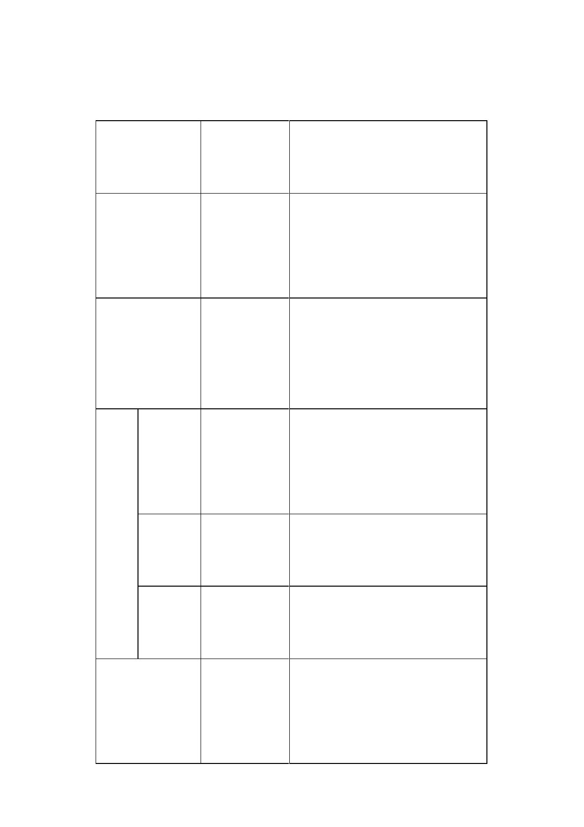
2. Button functions
Factions
Button
operations
Introduction
Work mode Double click F1
Then single click F1 to choose the
receiver work mode among “base”,
“rover”, “static”
Data link Double click F2
Then single click F2 to choose the
data link among “GSM”, ,
“External”
Static
Ele vatio n
angle
Long pressing
F1
Single press F1 to set elevation angle
to be 5 degrees,10 degrees, or 15
degrees
Collection
interval
Long pressing
F2
Single press F2 to set collectioninterval
to be 1s,5s,10s,15s
Static data
co llec t io n
Double click F2
Double click F2 to start collecting
static data
Confirm setting
Single press
power button
Then the receiver will speak out its
current work mode, data link, radio
tra
nsmit power, channel; meanwhile
19
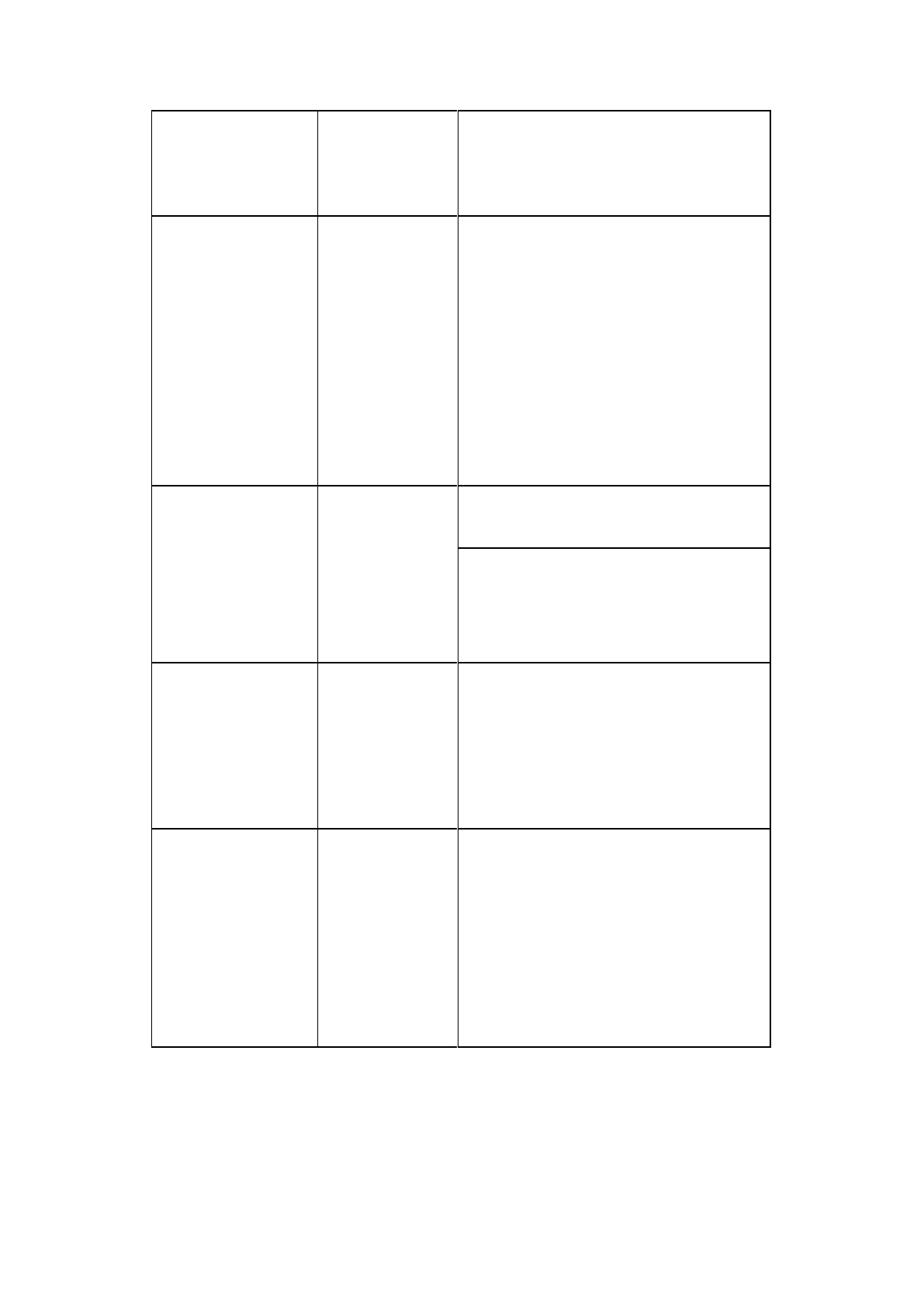
the power led will flash to hints its
power status
Auto-set base
F1+Power
button to turn
receiver
Press F1 while than press power
buttonat the same time to turn on the
receiver until hearing “Dingdong”.
Then the receiver sp
eak out its
current status.
Reset receiver and
selfinspection
Long press F1
Single press F1 to selfinspection.
Single press F2 to reset the mother
board.
Back receiver to
original settings
Long press F2
Single press F2, it will automatically
rectify, correct and reset to the original
settings.
Check currect
work status
Single click
power button in
non-settings
status
The receiver will speak out the work
mode and data link, at the same time
the power led flashing times hints the
power status.
20
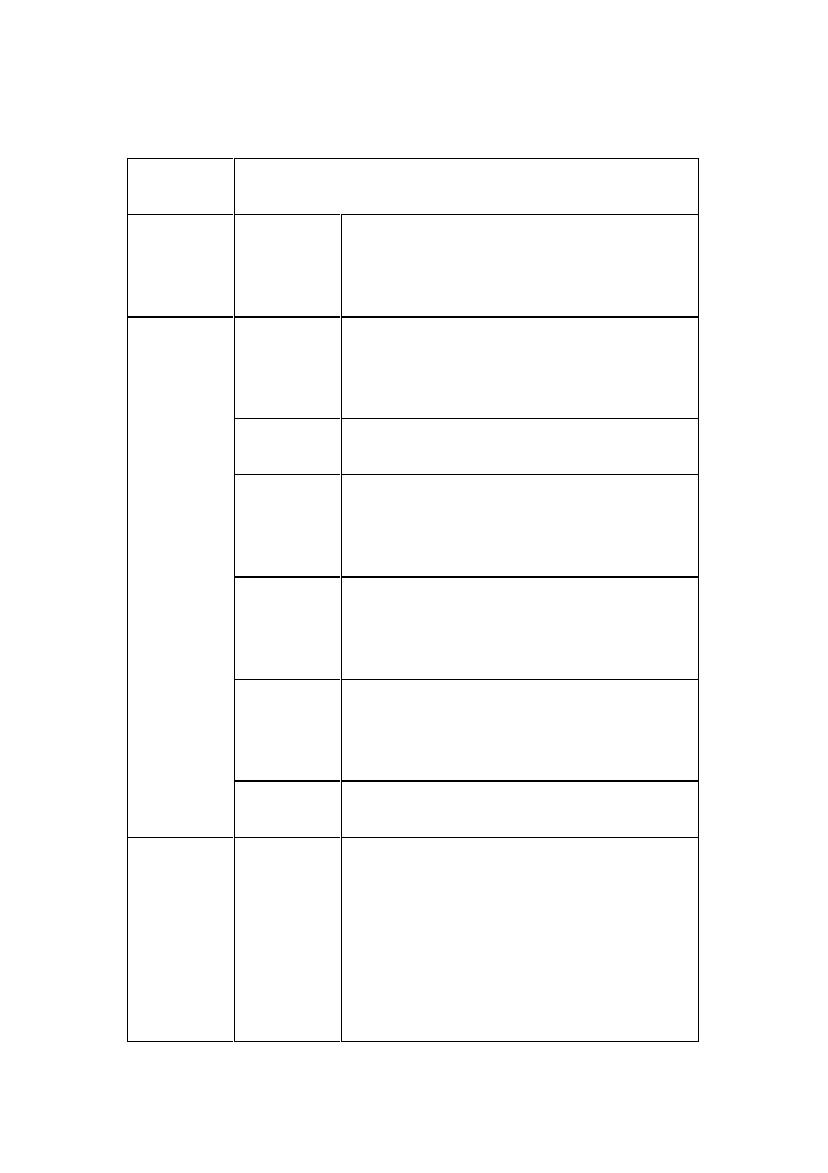
3. Led Status Instructions
Led Instruction
Power led
(yellow)
Always on
In normal voltage: internal battery voltage >7.6V,
external battery voltage >12.6V
Power led
(red)
Always on
In normal voltage: 7.2V<internal battery voltage
≤7.6V, 11V<external battery voltage ≤12.6V
Slo w flash Low power-pressure: inter≤7.2V,e xt erna l≤ 11V
Fast flash
Power status hints: one to
four times of one
minute
Always on
GSM module has been connected to internet
server successfully
Slo w flash
GSM module has been connected to internet
successfully
Fast flash GSM module is trying to connect to internet server
Data led (red
led for
status)
Slo w flash
1. getting correction data via GSM or radio (only
receiving corrections for rover while transmitting
for base)
2. co llec tio n s tatic data in static mode
21
Fast flash
Error in static mode (typically for no more flash
memory)
Always on
Communication module in error for getting data,
mainly resulted by problem in module so that no
data output
Satellite led
(green)
Always on More than 4 satellites tracked successfully
Slo w flash Loss satellites and try re-tracking
Off
1. mother board error resulting in no data output
while resetting receiver
2. mother board error resulting in no data output
while in static mode
4. Static Data Storage
The GNSS static data collected by A10 receiver will be stored in its
memor y or the SD card, in *.GNS format.
You can connect the A10 receiver with PC by USB port of GC-3
cable and then just copy the static data into your PC.
Note: in case of no more memory, the data led (the middle
led) will be fast flashing while stopping the current
static data collection.
22
5. RTK Data Storage
The controller can be connected with the receiver via Bluetooth or
cable, the data will be stored in the memory of the controller.
After fieldwork finished, you can connect the controller with PC by
the data cable, and then download the RTK data from the controller to PC
by copying.
6. Self-inspect and reset Receiver
Long press F1 button for more than 6 seconds, and then single press
F1 to self-inspect or single press F2 to reset the mother board.
Warning: reset receiver will make the next tracking satellite
time longer while needs users to set receiver work
mode again.
7. Format Receiver
Format A10 receiver by Receiver Management Software:
Connect A10 with PC by serial port of GC-3 cable
Turn on A10 receiver
Choose right serial port and open port
After connecting successfully: the S/N will be showed in the below
Click “Format/Delete All” to complete format receiver. After this
operation, all current data will be deleted forever.
23
Warning: Make sure all useful data has been copied to
another place for spare, because all data will be
deleted forever after this format.
8. Power Supply System
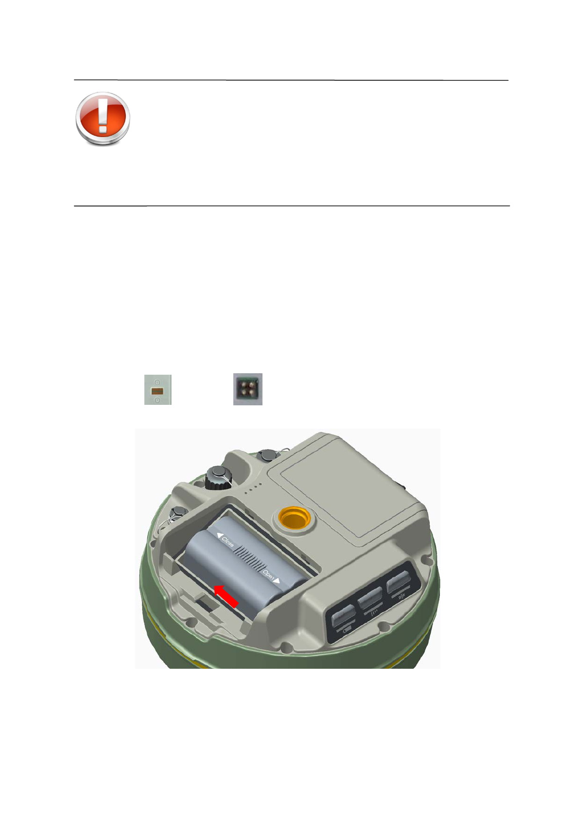
Install and Uninstall Battery
Install:
1. Match with the in the battery slot to put in the battery.
Figure 4-2
2. Insert battery towards “Close” end (see red arrow) to install it ok.
24
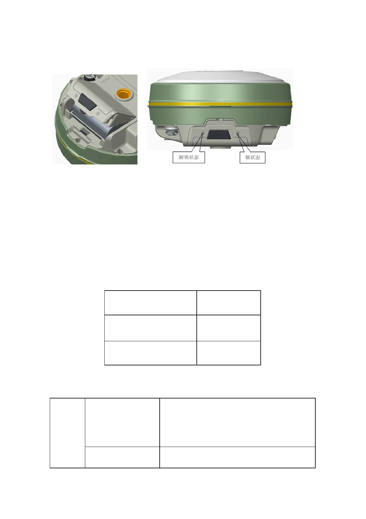
3. Close the battery cover.
Figure 4-3
Uninstall:
Slide the battery towards to the “Open” end, and then pull out battery.
A10 Receiver Battery Name and Model
Name Model
5000mAh lithium battery BL-5000
Lithium battery charger CL-8410
Power Supply
Power
supply
Power supply way
1. lithium battery;
2. eight-pin port and five-
pin port on the
mainframe for external power supply
Power range 6V ~ 36V
25
If use external power supply for A10 by the eight-pin port and
five-pin port on the mainframe, the power supply should be 6~36V with
current no less than 500 mAh.
When using both lithium battery and external battery, the receiver
will check the power pressure of both batteries and choose the higher one.
And please note that if use external power supply, must use the
specified external power supply from to avoid any destroy to the receiver.
Note: usually one A10 lithium battery can last 13 hours
for static. But the working time will be
decreased along with the more and more
charging times or in very low temperature.
Battery charging
BL-5000 lithium battery must be charged in specified CL-8410
charger for about 7.5 hours. The indicator led of the charger will be in red
while charging, and then green when charging finished.
Warning: 1. Only using specified charger and do not put the
battery into fire nor make it short circuit.
2. If heating, deformed, leaking, bad smells happens
while charging, using or storing, please stop using
the battery right now and change another one.
3. If the working time obviously become very short,
please stop using the battery right now and change
another one.
26

Technical Parameters
■ Introduction
■ Receiver
■ Ports
■ Function Key and Indicator Led
■ Intelligent Voice Module
■ Accuracy
■ Physical Feature
■ Working Environment
C
H
A
P
T
E
R
5
27

1. Introduction
Here we list out all Technical Parameters of A10 GNSS RTK
SYSTEM. The Technical Parameters will be a little different according to
your purchase order. Please make sure about your configuration then find
out Technical Parameters correspondingly.
2. Receiver
◎ GPS : Synchronous tracking L1 C/A, L2E, L2C, L5
◎ GLON ASS: Synchronous tracki ng L1 C/A , L1 P, L2 C/A (onl y for
GLONASS M) and L2P
◎ SBA S: Synchronous tracki ng L1 C/A , L5
◎ GIOVE-A:synchronous tracking L1 BOC, E5A, E5B and E5AltBOC
(optional)
◎ GIOVE-B :synchronous L1 CBOC, E5A, E5B and E5AltBOC
(optional)
◎ GALILEO:( Upgrade)
◎ A hi gh preci si on measurement i n the rel evant organs usi ng for gl obal
navigation satellite system
◎ Very l ow noi se GNSS carrier phase i n Surveyi ng, A ccuracy < 1 mm
within 1 HZ wide band
◎ M ature l ow el evati on-angle tracking technology
◎ Initialization time < 10 S
◎ Initialization Reliability > 99.9%
◎ 1 Hz, 2 H z, 5 Hz, 10 Hz, 20Hz and 50 Hz output (default 10Hz)
◎ Di fferential data format: sCMRx、CMR、CMR+、RTCM 2.1、2.2、
2.3、3.0、3.1、3.2
◎ N av i gati o n O utp ut For mat: A SCI I :NMEA-0183 GSV、AVR、RMC、
HDT、VGK、VHD、ROT、GGK、GGA、GSA、ZDA、VTG、GST、
PJT、PJK、BPQ、GLL、GRS、GBS
28

3. Ports
◎ 2 RS-232 serial ports
◎ 1 USB port
◎ 1 port for wireless blue-tooth communication
◎ 2 port for external DC pow er suppl y ( M ul ti pl ex)
◎ 1 SIM card slot
◎ 1 SI M card sl ot
◎ 1 SD card slot
◎ 2 built-in Li-ion battery groove
◎ 1 built-in communication module port
4. Function Key and LED
◎ 3 Panel buttons: 1 power switch key, 2 functional keys, with these
combination you can set all the function with voice and Indicator Led
flexibility
◎ 3 LEDs: 1 Satellite LED (Single color), 1 Communication LED ( Dual
Color) ,1 Power LED ( Dual Color)
5. Intelligent Voice Module
◎ Broadcasti ng functi on for each operati on i n E ngl i sh
◎ Support user defind voice
6. Accuracy
◎ Stati c, Fast Stati c: H ori zo ntal : ±( 2. 5+1×10⁻⁶D) mm
Vertical: ±(5+1×10⁻⁶D) mm
◎ RTK A ccuracy: Hori zontal : ±(10+1×10⁻⁶D) mm
Vertical: ±(20+1×10⁻⁶D) mm
29

7. Physical Feature
◎ W i th A RM 9 Core Control Chip, built-in 1GB Flash Memory
◎ Di mensi on: φ182mm×h96mm
◎ Weight: 1.25 kg( Incl. li-ion battery)
◎ A nti -impact from 2 meters free-falling, waterproof in 2 meters deep
water
◎ Li thi um battery. W i th 2 standard battery i n 5000 mAh , Voltage:7.4 V;
One Single battery can work continuously for 13 hours in static mode,
and 7 hours in 2 W transmitting power
◎ 6~ 28V external DC power supported, external and internal power
supply exchanged automatic
◎ Recei ver Pow er Consumpti on: 2.5W
8. Environment
◎ IP Standard: IP67, w aterproof, dust-proof and anti-impact.
◎ Worki ng temperature: -40℃~65 ℃, storage temperature: -40℃~75℃
◎ 100% Humidity non-condensing
30