Hi Target Surveying Instrument ZHDV100 GNSS RTK Receiver User Manual
Hi-Target Surveying Instrument Co., Ltd GNSS RTK Receiver
UserManual.wiki
>
Hi Target Surveying Instrument
>
ZHDV100 User Manual
User Manual
Navigation menu
Upload a User Manual
Namespaces
Wiki Guide
HTML
PDF
Info
Views
User Manual
Discussion / Help
Navigation
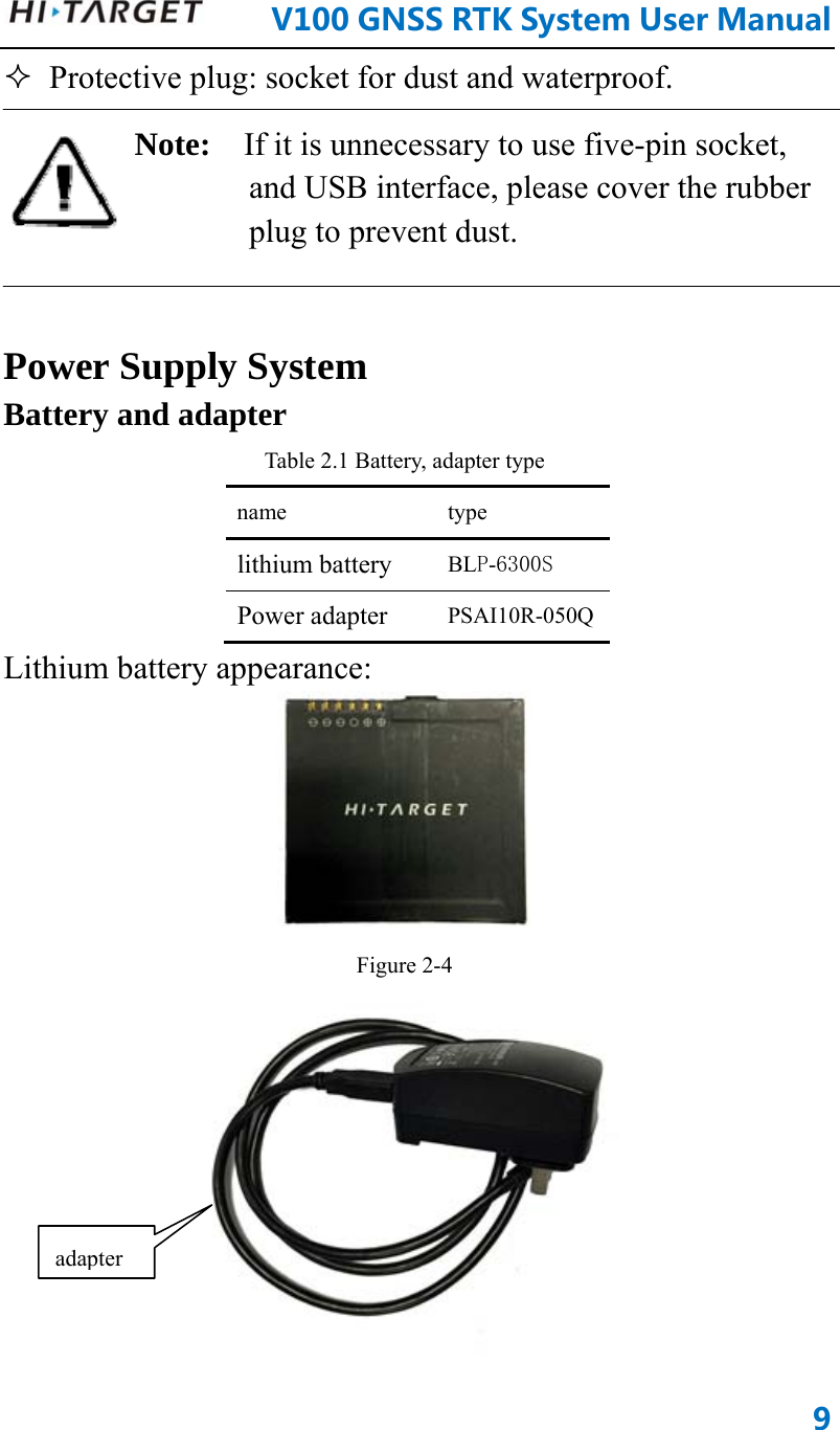
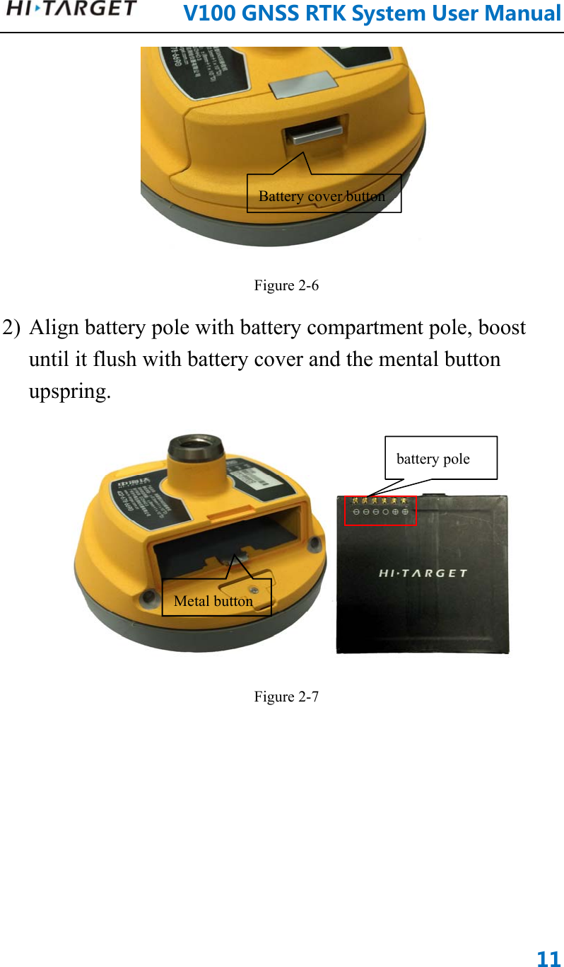
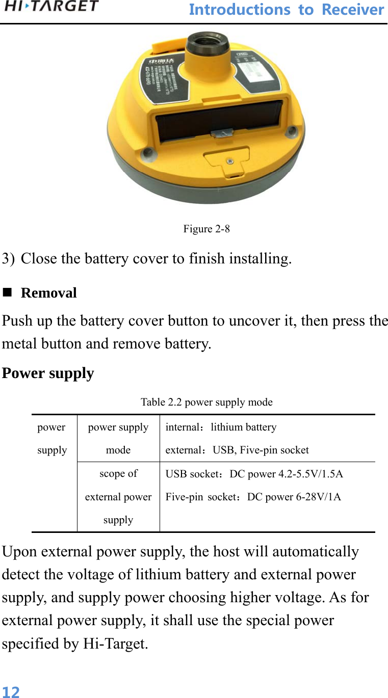
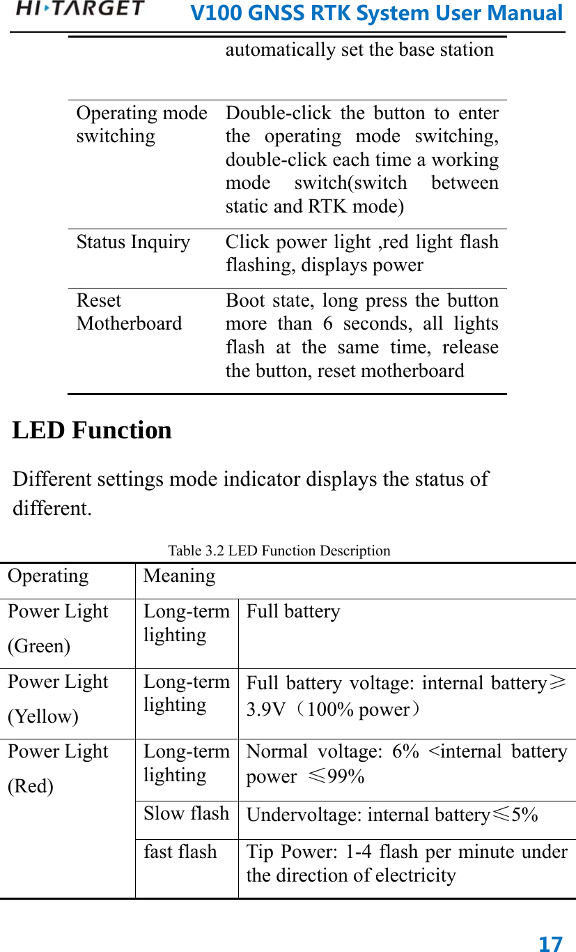
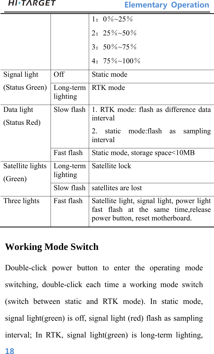
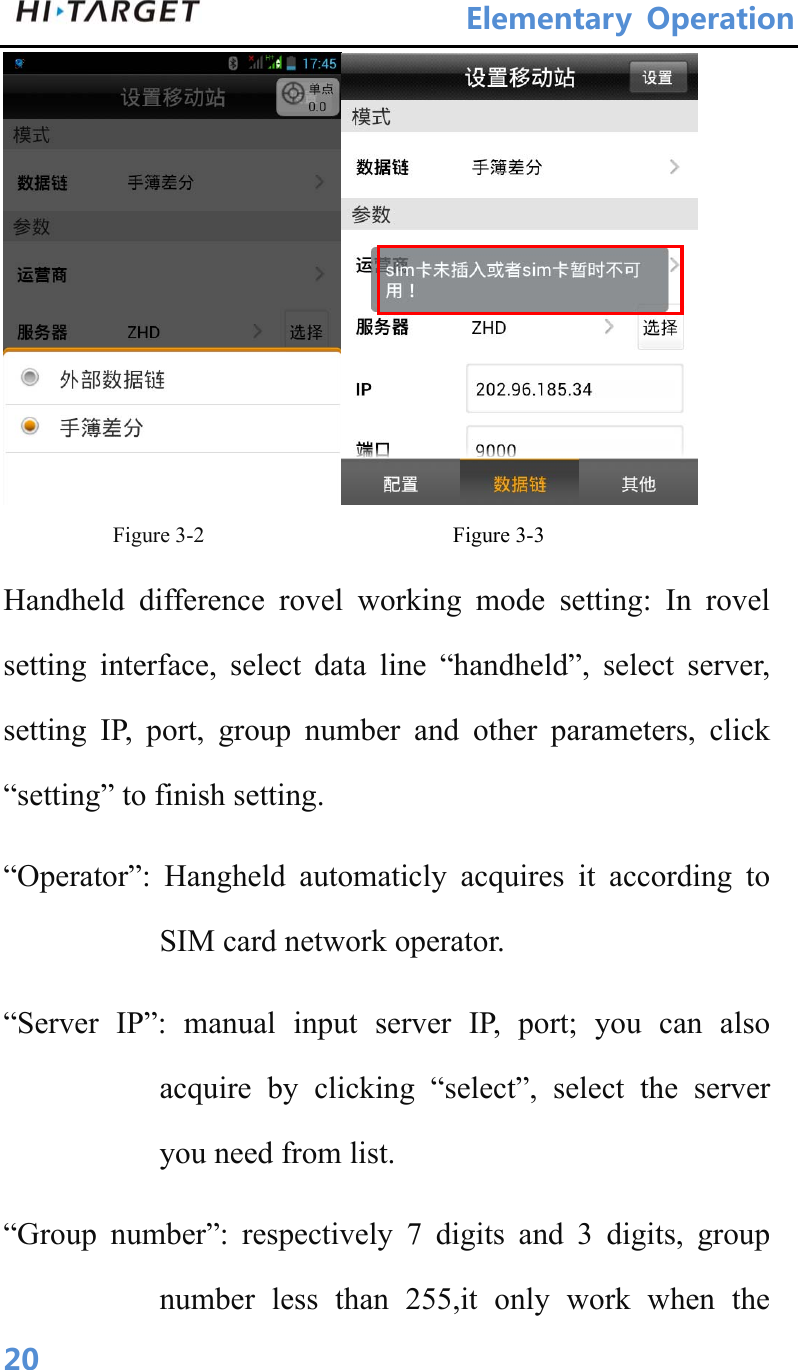
![Appendix40Schedule3 Key accessories information Table 3 key accessories information name version manufacturer Main performance index Motherboard BD970 Trimble 220channels Antenna Small measuring zero phase antenna Hi-Target Surveying Instrument Co., Ltd.51dB Databoard ZHD20150010B [PCBA] Hi-Target Surveying Instrument Co., Ltd._ FCC Caution: Any changes or modifications not expressly approved by the party responsible for compliance could void the user's authority to operate this equipment. This device complies with Part 15 of the FCC Rules. Operation is subject to the following two conditions: (1) This device may not cause harmful interference, and (2) this device must accept any interference received, including interference that may cause undesired operation. This device and its antenna(s) must not be co-located or operating in conjunction with any other antenna or transmitter. This equipment should be installed and operated with minimum distance 20cm between the radiator and your body. NOTE: This equipment has been tested and found to comply with the limits for a Class B digital device, pursuant to Part 15 of the FCC Rules. These limits are designed to provide reasonable protection against harmful interference in a residential installation. This equipment generates, uses and can radiate radio frequency energy and, if not installed and used in accordance with the instructions, may cause harmful interference to radio communications. However, there is no guarantee that interference will not occur in a particular installation. If this equipment does cause harmful interference to radio or television reception, which can be determined by turning the equipment off and on, the user is encouraged to try to correct the interference by one or more of the followingmeasures: -- Reorient or relocate the receiving antenna. -- Increase the separation between the equipment and receiver.](https://usermanual.wiki/Hi-Target-Surveying-Instrument/ZHDV100/User-Guide-2827251-Page-48.png)