Hi Target Surveying Instrument ZHDV100 GNSS RTK Receiver User Manual
Hi-Target Surveying Instrument Co., Ltd GNSS RTK Receiver
User Manual

I
Manual Revision
File number:YFZ-2015-0741
Revision Date Revision
Level Description
Nov.2015.04 1 V100 GNSS RTK System User Manual A/1
Preface
II
Preface
Introduction
Welcome to use Hi-target V100 receiver, this introduction is
applicable to Hi-Target V100 products. V100 is a new type of
GNSS receiver used for measurement. The introduction
describes how to install, set and use V100 products.
Experience Requirement
In order to help you better use Hi-Target series products,
Hi-Target suggests you carefully reading the instruction. If you
are unfamiliar with V100 products, please refer to
www.hi-target.com.cn
Tips for safe use
Note: the contents here generally are special
operations, needing your special attention.
Please read the contents carefully.
V100GNSSRTKSystemUserManual
III
Warning: the contents here generally are very
important. In case of failing to operate
based on warning contents, it will
damage the machine, lose the data, break
down the system and endanger personal
safety.
Exclusions
Before using the products, please carefully read the operating
instruction, and it will help you better use the product.
Hi-Target Surveying Instrument Co., Ltd will not assume the
responsibilities if you fail to operate the product according to
the requirements in operating instruction, or operate the
product wrongly because of failing to understand the operating
instruction.
Hi-Target is committed to constantly perfect product functions
and performance, improve service quality and reserve the
rights to change the contents in operating instruction without

Preface
IV
separate notice.
We have checked the consistency between contents in
instruction and software & hardware, without eliminating the
possibility of deviation. The pictures in operating instruction
are only used for reference. In case of inconformity with
products, the products shall prevail.
Technology and Service
If you have any technical issues, you can call company
technology department for help, we will answer your
question in time.
Relevant Information
You can get this introduction in the following ways:
1. After purchasing hi-target V100 receiver,there will be
“V100 GNSS RTK System User Manual” in the
instrument container to guide you how to operate
instrument.

V100GNSSRTKSystemUserManual
V
2. Log in hi-target official website, download the electronic
version introduction in “Download Center” → “Manual”
→ “Surveying Products”
Advice
If you have any advice or suggestion on V100, please call us
or Dial the national hotline: 400-678-6690. Your feedback
information will improve the production quality more.

Content
VI
Content
Product Introduction ...................................... 1
Preface ............................................... 2
Product Characteristics ............................... 3
Cautions for Use ...................................... 3
Introductions to Receiver ................................. 5
Receiver Appearance ................................... 6
Control Panel ......................................... 6
Upper Cover ........................................... 7
Bottom Cover .......................................... 7
Power Supply System ................................... 9
Environmental Requirements ........................... 13
Electronic Jamming ................................... 14
Elementary Operation ..................................... 15
Control Panel ........................................ 16
Function Key ......................................... 16
LED Function ......................................... 17
Working Mode Switch .................................. 18
Rovel Handheld Difference ............................ 19
Static Collection .................................... 22
Static Data Storage .................................. 24
Static Data Download ................................. 25
Firmware Upgrading ................................... 26
Technical Parameters ..................................... 28
GNSS Configuration ................................... 29
System Configuration ................................. 30
Built-in Communication ............................... 30
Control Panel ........................................ 30
External Interface ................................... 30
Electric Characteristics ............................. 30
Physical Characteristics ............................. 31
Environment Characteristics .......................... 31
Private Cloud Service ................................ 31
Socket and Main Accessories .............................. 32

V100GNSSRTKSystemUserManual
VII
Preface .............................................. 33
Five-pin Socket ...................................... 33
Five-wire ............................................ 34
Mini USB Cable ....................................... 36
Measurement Bench Marker ............................. 37
Schedule 1 control panel lights .......................... 38
Schedule2 factory default parameters ..................... 39

Product Introduction
1
Product Introduction
This chapter describes:
■ Preface
■ Product Characteristics
■ Cautions for Use
C
H
A
P
T
E
R
1
ProductIntroduction
2
Preface
V100 is a new subminiaturized type of GNSS receiver
used for measurement pushed forward by Hi-Target Brand,
used a delicate design, Magnesium alloy construction,
multi-satellite and multi-frequency technique, built-in
constellation motherboard, Bluetooth both with dual-mode and
long-distance , it is a realization of quick, efficient , safe
measurement GNSS receiver.
Warning: the instruction represents no standard
configuration. The articles within the
box can be adjusted according to
different user requirements. The
specific configuration shall be subject
to the outgoing list upon purchasing.
The suggestions before using the
machine: check whether the product
package is damaged; please open the
package carefully and confirm whether
the articles are consistent with
outgoing list; in case of loss or damage
in the product and its accessories,
please immediately contact with local
office or dealers; please carefully read
the operating instruction before
carrying, transporting and using the

V100GNSSRTKSystemUserManual
3
product.
Product Characteristics
A new generation of subminiaturized GNSS RTK,
equipped with new efficient intelligent real-time core
platform;
Using BDS constellation system, Support BDS, GPS,
GLONASS;
Subminiaturized zero-phase antenna ;
Built-in 4.0 standard long-distance dual-mode Bluetooth,
backward compatible 2.1standard Bluetooth;
Built-in 8GB large capacity data memory;
Equipped with iHand20 intelligent hand held or industrial
tablet PC;
Handbook controller receives differential signal;
Designed for the Android development of customized
smart metering software--Hi-Survey;
A key Multifunction;
New subminiaturized fuselage,Magnesium alloy structure,
more solid;
Cautions for Use
V100 receiver used Chemical resistance and impact
resistance design ,but we also need carefully use and
ProductIntroduction
4
maintenance the sophisticated instruments.
Warning: the receiver shall be in stipulated
temperature range upon using and
storage. The detailed requirements are
shown in ChapterⅣ:
Technical Parameters—> Environment
Characteristics.
In order to guarantee the quality of continuous tracking
observation and satellite signals, it is required that the
overhead observation station shall be open, without flaky
barriers above 15° elevating angle; in order to diminish the
interference of electromagnetic wave to GNSS satellite signals,
the observation station shall be free form strong
electromagnetic wave within the range of 200m, such as
television tower, microware station and high-voltage
transmission line; in order to avoid or reduce multiparty effect,
the observation station shall be far away from the terrain and
ground features with strong reflection against electromagnetic
wave signal, such as high-rise buildings, waters, etc.

V100GNSSRTKSystemUserManual
5
Introductions to Receiver
This chapter describes:
■ Receiver Appearance
■ Control Panel
■ Upper Cover
■ Bottom Cover
■ Power Supply System
■ Environmental Requirements
■ Electronic Jamming
C
H
A
P
T
E
R
2
IntroductionstoReceiver
6
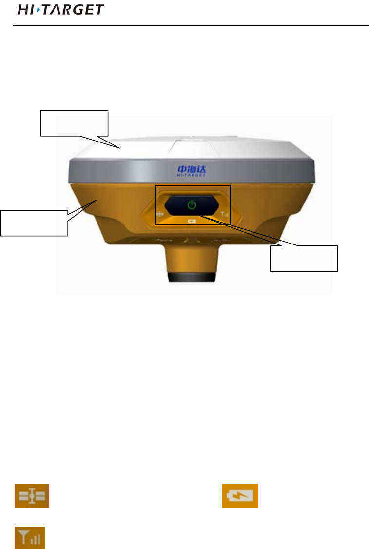
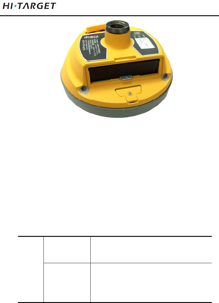
Receiver Appearance
The product appearance is divided into three sections,upper
cover, bottom cover and control panel.
Figure 2-1
Control Panel
The control panel includes a power switch button, three
indicators, namely satellite lights, power light (bi-color light),
signal light (bi-color light).
Satellite light power light
signal light
Power Button Functions: Startup, shutdown, operating mode
switching, automatically set the base station, reset the board
upper cover
bottom cover
control panel
V100GNSSRTKSystemUserManual
7
and so on.
Upper Cover
Figure 2-2
Loss Prevention boss: boss can effective anti-wear;
Color Mode: appearance of the structure, Clear , beautiful,
drop
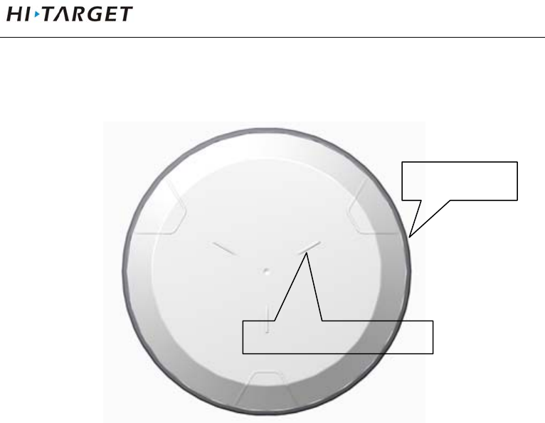
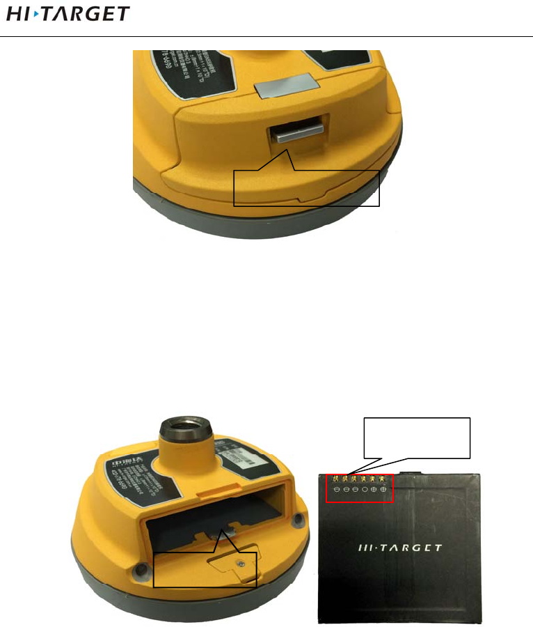
Bottom Cover
Including battery compartment, five-pin socket,Mini USB
interface.
Loss Prevention boss
Color Mode

IntroductionstoReceiver
8
1- Screw connection 2- Battery compartment 3- Five-pin socket 4-Mini USB
interface 5- protective plug
Figure 2-3
Connection screw: for the instrument fixed to the base or
the pole.
Battery compartment: for housing lithium batteries.
Five-pin socket: For connection to the host and external
data links and external power source.
Mini USB interface: For connection to the host and
external devices, upgrade firmware and download
The static data can also charge or supply electricity to the
host.
3
4
5
2
1
V100GNSSRTKSystemUserManual
9
Protective plug: socket for dust and waterproof.
Note: If it is unnecessary to use five-pin socket,
and USB interface, please cover the rubber
plug to prevent dust.
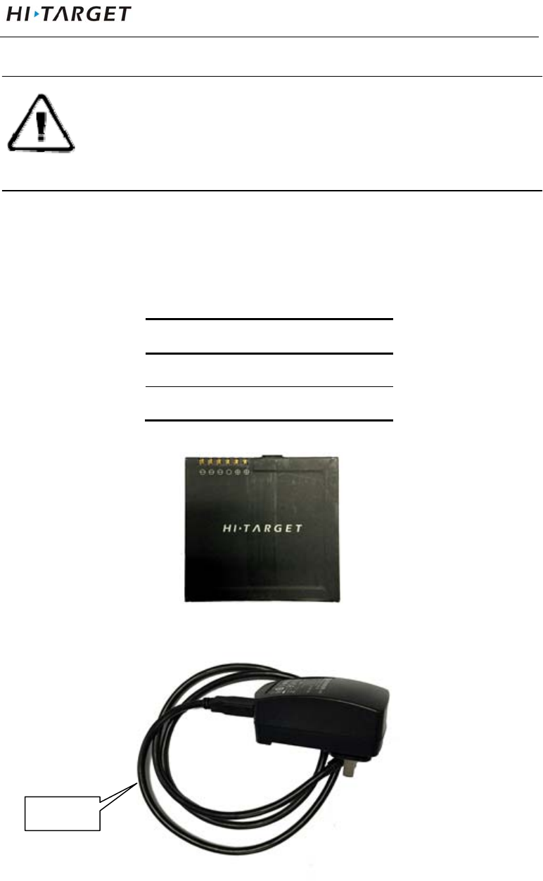
Power Supply System
Battery and adapter
Table 2.1 Battery, adapter type
name type
lithium battery BLP-6300S
Power adapter PSAI10R-050Q
Lithium battery appearance:
Figure 2-4
ada
p
te
r
IntroductionstoReceiver
10
Figure 2-5
Recharge
V100 lithium battery shall use PSAI10R-050Q power
adapter to charge, about 7 hours of charging time.
Warning: 1. only the battery and charger configured
by the manufacturer can be used; the
battery shall not be thrown into fire or
used in metal short circuit electrode.
2. It shall stop using in case of heating,
deformation, liquid leakage, smelling or
other abnormal reactions during using,
charging or storage process. It shall
exchange new battery.
3. It shall stop using in case of the service
time of battery is shortened , the battery
is aged, it shall exchange new battery.
4. Charge environment can't be higher than
40℃.
Battery installation and removal
Installation
1) Push up the battery cover button, then uncover it.
V100GNSSRTKSystemUserManual
11
Figure 2-6
2) Align battery pole with battery compartment pole, boost
until it flush with battery cover and the mental button
upspring.
Figure 2-7
Battery cover button
battery pole
Metal button
IntroductionstoReceiver
12
Figure 2-8
3) Close the battery cover to finish installing.
Removal
Push up the battery cover button to uncover it, then press the
metal button and remove battery.
Power supply
Table 2.2 power supply mode
power
supply
power supply
mode
internal:lithium battery
external:USB, Five-pin socket
scope of
external power
supply
USB socket:DC power 4.2-5.5V/1.5A
Five-pin socket:DC power 6-28V/1A
Upon external power supply, the host will automatically
detect the voltage of lithium battery and external power
supply, and supply power choosing higher voltage. As for
external power supply, it shall use the special power
specified by Hi-Target.
V100GNSSRTKSystemUserManual
13
NOTE: 1. The service life of lithium battery will
decrease along with the decrease in
temperature and increase in
charging-discharging times. A new
6300 mAh lithium battery can be used
for 7 hours upon collection of static
data or rovel operation.
2. In order to prolong the service life of
battery, it shall charge the battery
within 24 hours after using up, or the
battery performance will be damaged.
3. When the battery is not used for a long
time, please charge once every month
to prolong the service life of battery.
Environmental Requirements
The receiver shall operate in dry working environment
regardless of waterproof materials. In order to advance the
stability and service cycle of receiver, the receiver shall be
prevented from extreme environment, such as:
Moisture
Temperatures above 60 degrees centigrade
Below - 40 degrees centigrade

IntroductionstoReceiver
14
Corrosive liquids or gases
Electronic Jamming
The receiver shall not be installed in the place near to strong
electric power and interference signal, such as:
Oil duct (spark plugs)
Television and computer display
Generator
Battery-operated motor cycle
DC-AC power supply changeover equipment
Fluorescent lamp
Power supply

V100GNSSRTKSystemUserManual
15
Elementary Operation
This chapter describes:
■ Control Panel
■ Function Key
■ LED Function
■ Working Pode Switch
■ Rovel Handheld Difference
■ Static Collection
■ Static Data Storage
■ Static Data Download
■ Firmware Upgrading
C
H
A
P
T
E
R
3
ElementaryOperation
16
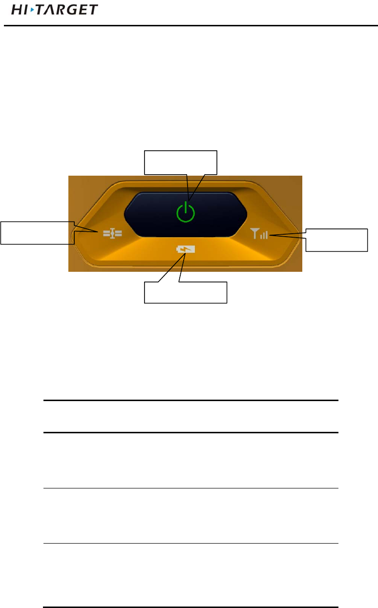
Control Panel
Most settings and operations of receiver are completed using a
key on control panel.
Figure 3-1
Function Key
Table 3.1 Description of power key operation
Operation name Note
on Shutdown state, long press the
button one second boot, all light
are on
off Boot mode, long press the button
three seconds, all lights double
fast flash, release the button,
Automatic
setting station
Shutdown mode, press the button
six seconds long, all lights
double fast flash, release the
button, the instrument will
Satellite light
Power key
Status light
Power light

V100GNSSRTKSystemUserManual
17
automatically set the base station
Operating mode
switching
Double-click the button to enter
the operating mode switching,
double-click each time a working
mode switch(switch between
static and RTK mode)
Status Inquiry Click power light ,red light flash
flashing, displays power
Reset
Motherboard
Boot state, long press the button
more than 6 seconds, all lights
flash at the same time, release
the button, reset motherboard
LED Function
Different settings mode indicator displays the status of
different.
Table 3.2 LED Function Description
Operating Meaning
Power Light
(Green)
Long-term
lighting
Full battery
Power Light
(Yellow)
Long-term
lighting
Full battery voltage: internal battery≥
3.9V(100% power)
Power Light
(Red)
Long-term
lighting
Normal voltage: 6% <internal battery
power ≤99%
Slow flash Undervoltage: internal battery≤5%
fast flash Tip Power: 1-4 flash per minute under
the direction of electricity

ElementaryOperation
18
1:0%~25%
2:25%~50%
3:50%~75%
4:75%~100%
Signal light
(Status Green)
Off Static mode
Long-term
lighting
RTK mode
Data light
(Status Red)
Slow flash 1. RTK mode: flash as difference data
interval
2. static mode:flash as sampling
interval
Fast flash Static mode, storage space<10MB
Satellite lights
(Green)
Long-term
lighting
Satellite lock
Slow flash satellites are lost
Three lights Fast flash Satellite light, signal light, power light
fast flash at the same time,release
power button, reset motherboard.
Working Mode Switch
Double-click power button to enter the operating mode
switching, double-click each time a working mode switch
(switch between static and RTK mode). In static mode,
signal light(green) is off, signal light (red) flash as sampling
interval; In RTK, signal light(green) is long-term lighting,
V100GNSSRTKSystemUserManual
19
signal light (red) flash as difference data interval.
NOTE:Working mode switch: You can also switch
by handheld, please refer to the specific
operation "Hi-Survey Software User's
Guide" RTK mode setting : equipment →
base\rovel → data line; static mode: setting
equipment → Accessibility → static
capture settings.
Rovel Handheld Difference
When the host working mode is rovel, the data line has two
types: external data link and handheld difference. Handheld
difference refers to connect server by handheld network and
regard it as the RTK, use handheld network module to
dial-up. After connecting server, it transmits the received
difference data through Bluetooth, the host can be the
network RTK without SIM card. The capability apples to the
existing network module of handheld.
ElementaryOperation
20
Figure 3-2 Figure 3-3
Handheld difference rovel working mode setting: In rovel
setting interface, select data line “handheld”, select server,
setting IP, port, group number and other parameters, click
“setting” to finish setting.
“Operator”: Hangheld automaticly acquires it according to
SIM card network operator.
“Server IP”: manual input server IP, port; you can also
acquire by clicking “select”, select the server
you need from list.
“Group number”: respectively 7 digits and 3 digits, group
number less than 255,it only work when the
V100GNSSRTKSystemUserManual
21
base and rovel should setting the same
parameters.
“Network”: ZHD and CORS, select ZHD when using
hi-target server, select CORS when using CORS
network.
Figure 3-4 Figure 3-5
Checking difference transmitting state: check difference
transmitting state in suspend:
:handheld difference(transmitting)
: handheld difference (not transmitting)
ElementaryOperation
22
Checking difference network state: click to the
“difference network state” interface.
If user have connected receiver and set as rovel handheld
difference operation,click directly “disconnect” to stop
handheld transmitting difference; click “connect to server” to
transmits difference.
Figure 3-6
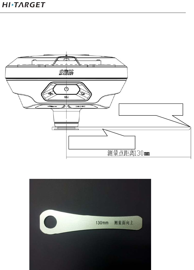
Static Collection
1. Set up the instrument at the measurement point, the point
is to strictly, and leveling.
2. Measure instrument height, High measuring instrument
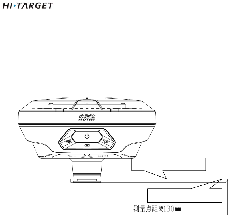
V100GNSSRTKSystemUserManual
23
shall be measured to the center point mark stone on top
of the instrument of measurement reference
member.V100 receiver measuring reference member
radius 0.130m.
Figure 3-7
3. Record point name, instrument number, instrument
height, beginning observing time.
4. Boot, set the host to the static measurement mode.
Satellite light flashing indicates it is searching for
satellites. Satellite light turn to long-term lighting from
the flashing status indicates locked satellites. In static
mode, signal light (red) flashes once based to setting
measurement reference
height measurement point
ElementaryOperation
24
sampling interval, indicating that the acquisition of one
epoch.
5. After the measurement is completely shutdown, record
shutdown time.
6. Download processing data.
Note :You cannot move the base equipment and
change acquisition parameters in the data
collection.
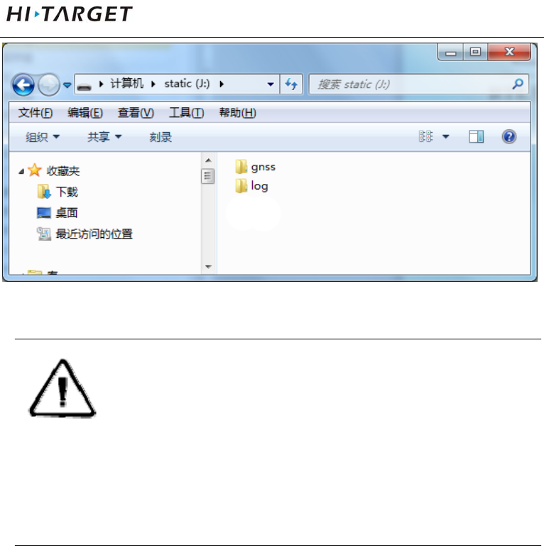
Static Data Storage
Collected GNSS static data is stored in "static" disk that 8GB
internal storage of V100 receiver, effective storage space is
6.6GB, includes two folders: log and gnss, log folder stores log
information, the data format storage in gnss folder is * .gns.
You can connect to computer through USB data cable of
random configuration, copy static data to your computer in U
disk operation mode.
V100GNSSRTKSystemUserManual
25
Figure 3-8
Note:When the receiver storage space is less than
10MB, data light (red) fast flash, and it
stop recording data, the existing data files
will not be overwritten.
Static Data Download
Receiver file management download directly without
download programs in the way of U disk storage. It can only
download static data and can’t write or read the receiver.
The receiver can download data like U disk , it need Mini USB
data cable, one end of Mini USB data cable is connected to
computer USB port and the other end is connected to Mini
USB port of receiver. It will appear “static” disk after
connection, then opening the disk, copy the collected static
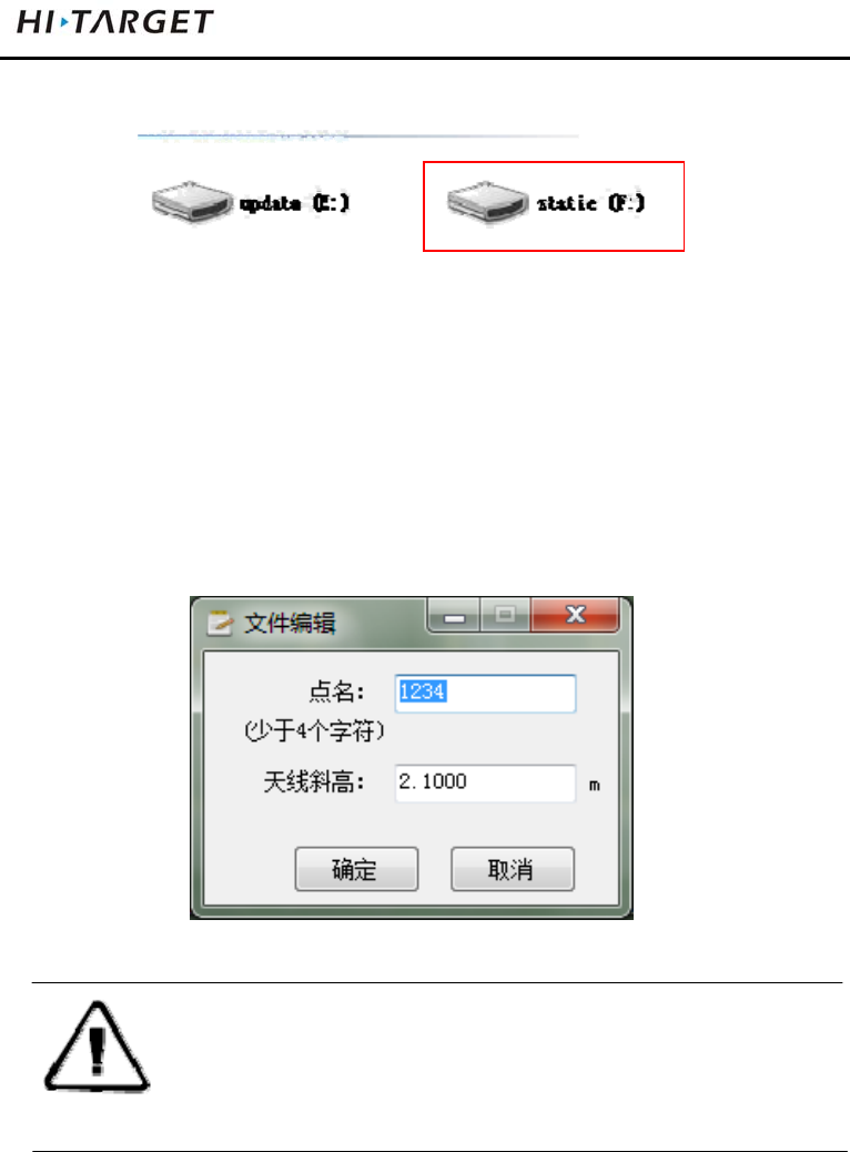
ElementaryOperation
26
file.
Figure 3-9
The steps of modify point name and antenna height of
downloaded static file are:
1. Choose *. GNS files and double click the mouse.
2. Modify point name and input antenna height in the popping
up dialogue of “file edit”, and then click “OK”.
Figure 3-10
Note:The static files in removable disk can be
deleted by handheld software rather than
deleting directly.
Firmware Upgrading
Host firmware can be manually upgraded through the U disk
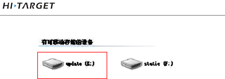
V100GNSSRTKSystemUserManual
27
way.
Figure 3-11
1. Open receiver, connect to computer by a random
configuration USB cable. Open “my computer”, there will
be "update" upgrading disk.
2. Copy host firmware (it can be downloaded from the official
website or obtained from the technician) to "update"
upgrading disk, then remove U disk, unplug the cable,
restart the receiver to complete the upgrading.

Technical parameters
28
Technical Parameters
This chapter describes:
■ GNSS Configuration
■ System Configuration
■ Built-in Communication
■ Control Panel
■ External Interface
■ Electric Characteristics
■ Physical Characteristics
■ Environment Characteristics
■ Private Cloud Service
C
H
A
P
T
E
R
4

V100GNSSRTKSystemUserManual
29
GNSS Configuration
System core:use international first-class PCC new efficient
intelligent real-time core
Channel number:220
BDS:B1、B2
GPS:L1 C/A、L2E、L2C、L5
GLONASS:L1 C/A、L1 P、L2 C/A (Limited GLONASS
M and L2P)
GALILEO:Upgrading reserve
Output format:ASCⅡ:NMEA-0183 and binary : Trimble
GSOF
Difference support:sCMRx、CMR、CMR+、
RTCM2.1/2.2/2.3/3.0/3.2
RTK positioning accuracy:
Plane:±(8mm+1×10⁻⁶D)
Height:±(15 mm+1×10⁻⁶D)
Static, rapid static accuracy:
Plane:±(2.5 mm+1×10⁻⁶D)
Height:±(5 mm+1×10⁻⁶D)
Code difference:0.4m
SBAS difference:1.2m
Initialization time:typical 8s

Technical parameters
30
Initialization reliability : >99.9%
Data update rate : <20Hz
System Configuration
Operation system:intelligent real-time system
boot time: 1s
Data storage:built-in 8GB storage
Built-in Communication
Daul mode Bluetooth communication
Control Panel
Panel: one key
Indicator:three bi-color LED lights
External Interface
1 USB interface
1 five-pin interface
Electric Characteristics
Battery : high capacity lithium 6300mAh/3.7V, removable,
continuously operating time reaches above 7 hours
Voltage: USB interface:DC 4.2-5.5V/1.5A; five-pin
interface: DC6-28V/1A
Power consumption: 3.2W

V100GNSSRTKSystemUserManual
31
Physical Characteristics
Core control chip CotexA8, built-in 16GB Flash memory
Size:127.5mm×57mm
Weight: ≤700g (lithium battery)
Material:magnesium alloy material
Environment Characteristics
Protection class:IP67; protect 2m temporary soaking
underwater, Completely prevent dust
Working temperature: -40 ℃ ~ 60 ℃
Storage temperature:-40℃~75℃
Relative humidity: 100%, anti-condensation
Private Cloud Service
The cloud service supports for 24 hours,realizes integrated technique of indoor
work and field work, remote manage serve and support equipment. it manages
team project, shares parameters and control points, post backs real-time verify
and note track of result data by cloud background. After the user’s
authorization, terminal servers can remotely provide customers with technical
support, including system version upgrading, system registration, remote
debugging and other services .

SocketandMainAccessories
32
Socket and Main
Accessories
This chapter describes:
■ Preface
■ Five-pin Socket
■ Five-wire
■ Mini USB Wire
■ Measurement Bench Marker
C
H
A
P
T
E
R
5
V100GNSSRTKSystemUserManual
33
Preface
The chapter will introduce the appearance and application of
main interface and accessories of V100. The following
equipment does not represent all V100 users purchased. There
will be different according to different configurations, the
specific configuration shall be subject to the delivery order
upon purchasing.
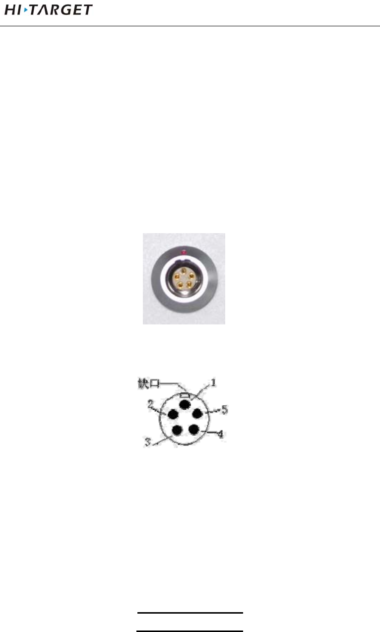
Five-pin Socket
Figure 5-1
Figure 5-2
1. Five-pin socket:Also known as COM2 socket, normally
used to connect the host and external data link and
external power.
Table5.1 five-pin socket Signal Description
Five-core signal
SocketandMainAccessories
34
1 GND
2 GND
3 Vin
4 RXD
5 TXD
2. All the circular sockets of this company start numbering
pin in counterclockwise positive; circular pins start
numbering pin in welding face counterclockwise.
3. All the above data out(TXD), in(RXD) signals explain by
receivers. TXD is transmitting receiver data signal line,
RXD is receiving receiver data signal line.
4. In addition, the computer serial port DB9 pin connector
signals: 2 (RXD computer data reception signal line), 3
(TXD computer data transmission signal line), 5 (GND
signal ground). Referred to as "2 reception 3
transmission."
Note:Above all are facing the host, the bottom
socket of host is front icon (ie plug weld
surface).
Five-wire
V100GNSSRTKSystemUserManual
35
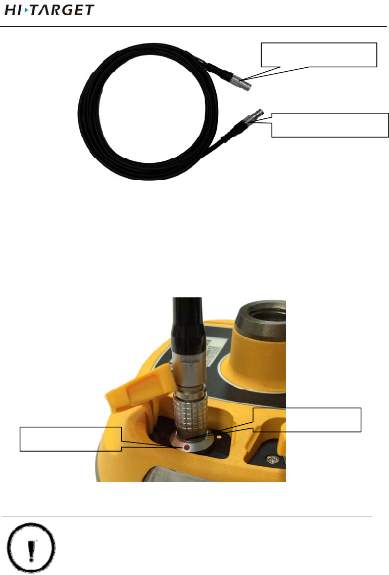
Figure 5-3
Five-wire: Connecting host and External radio, transmitting
difference data;
Figure 5-4
Warning: 1. when connecting various plugs of
receiver, it shall align the red point in
line joint at the red point in receiver
Plug the red dot
Socket red dot
five-pin socket
five-pin socket
SocketandMainAccessories
36
socket, or it will damage the receiver
socket and plugs of various lines.
2. When plug out the plug, directly
grasp the sliding collar and pull out
the plug with effort. It shall not rotate
the plug.
3. After using the cable it shall place the
cable in the place that are difficult for
extrusion to prevent damaging the
plug.
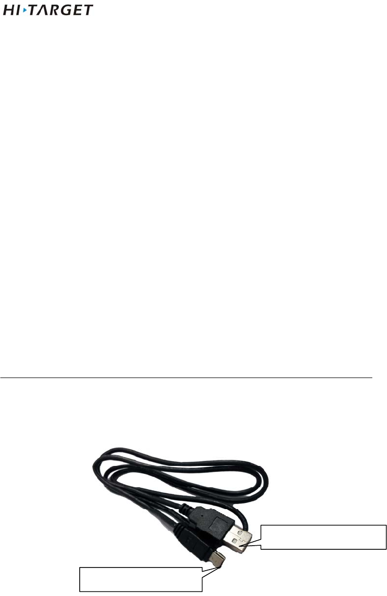
Mini USB Cable
Figure 5-6
Mini USB cable, one end is a standard USB connector on
Mini USB interface
Standard USB interface
V100GNSSRTKSystemUserManual
37
one end and Mini USB interfaces.
Measurement Bench Marker
Figure 5-7
Figure 5-8
m
easurement
b
ench
m
arke
r
measurement height point

附录
38
Schedule 1 control panel lights
Table 1 control panel lights illustrate
Operating Meaning
Power Light
(Green)
Long-term
lighting
Full battery
Power Light
(Yellow)
Long-term
lighting
Full battery voltage: internal battery≥3.9V(100%
power)
Power Light
(Red)
Long-term
lighting
Normal voltage: 6% <internal battery power ≤99%
Slow flash Undervoltage: internal battery≤5%
fast flash Tip Power: 1-4 flash per minute under the direction
of electricity
1:0%~25%
2:25%~50%
3:50%~75%
4:75%~100%
Signal light
(Status Green)
Off Static mode
Long-term
lighting
RTK mode
Data light
(Status Red)
Slow flash 1. RTK mode: flash as difference data interval
2. static mode:flash as sampling interval
Fast flash Static mode, storage space<10MB
Satellite lights
(Green)
Long-term
lighting
Satellite lock
Slow flash satellites are lost
Three lights Fast flash Satellite light, signal light, power light fast flash at
the same time,release power button, reset
motherboard.
V100GNSSRTKSystemUserManual
39
Schedule2 factory default parameters
Table 2 Factory default parameters
Options Content The factory set parameters
System
parameters
Working mode Rover
Data Link Handheld difference
Differential Mode RTK
Text format RTCM(3.2)
Height cut-off angle 10
GPS boot
BDS boot
GLONASS boot
Static collection interval 5s
Static Elevation angle 10
other none
Appendix
40
Schedule3 Key accessories information
Table 3 key accessories information
name version manufacturer Main performance
index
Motherboard BD970 Trimble 220channels
Antenna Small measuring
zero phase antenna
Hi-Target Surveying
Instrument Co., Ltd.
51dB
Databoard ZHD20150010B
[PCBA]
Hi-Target Surveying
Instrument Co., Ltd.
_
FCC Caution: Any changes or modifications not expressly approved by the party
responsible for compliance could void the user's authority to operate this equipment.
This device complies with Part 15 of the FCC Rules. Operation is subject to the
following two conditions: (1) This device may not cause harmful interference, and (2)
this device must accept any interference received, including interference that may
cause undesired operation.
This device and its antenna(s) must not be co-located or operating in conjunction with
any other antenna or transmitter.
This equipment should be installed and operated with minimum distance 20cm
between the radiator and your body.
NOTE: This equipment has been tested and found to comply with the limits for a
Class B digital device, pursuant to Part 15 of the FCC Rules.
These limits are
designed to provide reasonable protection against harmful interference in a
residential installation. This equipment generates, uses and can radiate radio
frequency energy and, if not installed and used in accordance with the
instructions, may cause harmful interference to radio communications.
However, there is no guarantee that interference will not occur in a particular installation.
If this equipment does cause harmful interference to radio or television reception,
which can be determined by turning the equipment off and on, the user is
encouraged to
try to correct the interference by one or more of the followingmeasures:
-- Reorient or relocate the receiving antenna.
-- Increase the separation between the equipment and receiver.

V100GNSSRTKSystemUserManual
41
-- Connect the equipment into an outlet on a circuit different from that to which the
receiver is connected.
-- Consult the dealer or an experienced radio/TV technician for help.