Hi Target Surveying Instrument ZHDV90PLUS GNSS RTK User Manual Manual
Hi-Target Surveying Instrument Co., Ltd GNSS RTK Manual
Manual

Preface
Introduction
The introduction is applicable to V90 Plus products. V90 is a
new type of GNSS receiver used for measurement. The
introduction describes how to install, set and use V90
products.
In order to help you better use Hi-Target series products,
Hi-Target suggests you carefully reading the instruction. If you
are unfamiliar with V90 products, please refer to
www.hi-target.com.cn/en/
Tips for safe use
Note: the contents here generally are special
operations, needing your special attention.
Please read the contents carefully.

II
Warning: the contents here generally are very
important. In case of failing to operate
based on warning contents, it will damage
the machine, lose the data, break down the
system and endanger personal safety.
Exclusions
Before using the products, please carefully read the operating
instruction, and it will help you better use the product.
Hi-Target Surveying Instrument Co., Ltd will not assume the
responsibilities if you fail to operate the product according to
the requirements in operating instruction, or operate the
product wrongly because of failing to understand the operating
instruction.
Hi-Target is committed to constantly perfect product functions
and performance, improve service quality and reserve the
rights to change the contents in operating instruction without
separate notice.
We have checked the consistency between contents in
instruction and software & hardware, without eliminating the
possibility of deviation. The pictures in operating instruction
are only used for reference. In case of inconformity with
products, the products shall prevail.
IV
Content
Product Introduction ...................................... 6
Preface ............................................... 7
Product Characteristics ............................... 8
Cautions for Use ...................................... 8
Introductions to Receiver ................................ 10
Receiver Appearance .................................. 11
Control Panel ........................................ 11
Upper Cover .......................................... 12
Bottom Cover ......................................... 12
Batteries ............................................ 14
Environmental Requirements ........................... 15
Electronic Jamming ................................... 16
Elementary Operation ..................................... 17
Control panel ........................................ 19
Function Key ......................................... 19
Status Inquiry ....................................... 20
LED Function ......................................... 20
Start and Stop Receiver .............................. 21
Reset motherboard .................................... 22
Auto set basestation ................................. 22
Static collection .................................... 22
Static data storage .................................. 24
RTK data storage ..................................... 25
U disk data download ................................. 26
Firmware ............................................. 27
Electronic bubble .................................... 28
Electronic bubble calibration ........................ 29
WiFi password setting ................................ 31
Power Supply System .................................. 33
SIM Card/USIM Card ................................... 38
Micro SD card ........................................ 40
Technical parameters ..................................... 42
GNSS Section ......................................... 43
Receiver Accuracy .................................... 43
Interface ............................................ 44
Function keys and indicators ......................... 44
Physical Characteristics ............................. 44
Environment .......................................... 45
Socket and Main Accessories .............................. 46
Preface .............................................. 47
Five-pin socket ...................................... 47
Five-wire ............................................ 48
Mini USB Interface ................................... 49
Mini USB cable ....................................... 49
Antenna Interface .................................... 50
Schedule 2 control panel lights .......................... 51

HI-TARGET 接收机介绍
6
Product Introduction
This chapter describes:
■ Preface
■ Product characteristics
■ Cautions for use
C
H
A
P
T
E
R
1

Preface
V90Plus is a new type of GNSS receiver used for measurement pushed
forward by Hi-Target Brand,used a new design,Magnesium alloy
construction,Linux3.2.0 operating system,Combined gravitational acceleration
sensor, WiFi connectivity, it is a realization of lightweight, intelligent, easy to
use measurement GNSS receiver.
Warning: 1、V90Plus receiver best to use 3G SIM card, if you
still use 2G SIM card to work, affect instrument
performance or operating units caused economic losses, the
company will not be responsible!
2、the instruction represents no standard configuration. The
articles within the box can be adjusted according to different
user requirements. The specific configuration shall be subject
to the outgoing list upon purchasing. The suggestions before
using the machine: check whether the product package is
damaged; please open the package carefully and confirm
whether the articles are consistent with outgoing list; in case
of loss or damage in the product and its accessories, please
immediately contact with local office or dealers; please
carefully read the operating instruction before carrying,
transporting and using the product.
HI-TARGET 接收机介绍
8
Product Characteristics
◇ A new generation of small intelligent BDS RTK,equipped with top
drive core,provided intelligent mapping of the overall solution;
◇ Using multi-satellite and multi-frequency GNSS units,Support BDS,
GPS, GLONASS.
◇ Equipped with CotexA8 platform、mass storage (16GB + SD card);
◇ With WiFi / 3G connectivity, to achieve long-distance transmission of
data;
◇ Gravity acceleration sensor (electronic bubble);
◇ Equipped with iHand20 intelligent hand held;
◇ Designed for the Android development of customized smart metering
software--Hi-Survey;
◇ A key Multifunction;
◇ New look,Magnesium alloy structure,more solid;
◇ Static data Dual Format storage(*.GNS / RINEX data)。
Cautions for Use
V90 Plus receiver used Chemical resistance and impact resistance
design ,but we also need sophisticated instruments careful use and
maintenance.
Warning: the receiver shall be in stipulated temperature range
upon using and storage. The detailed requirements are
shown in Chapter V: Technical Parameters —>
Environment.

In order to guarantee the quality of continuous tracking
observation and satellite signals, it is required that the
overhead observation station shall be open, without flaky
barriers above 15° elevating angle; in order to diminish the
interference of electromagnetic wave to GNSS satellite signals,
the observation station shall be free form strong
electromagnetic wave within the range of 200m, such as
television tower, microware station and high-voltage
transmission line; in order to avoid or reduce multipath effect,
the observation station shall be far away from the terrain and
ground features with strong reflection against electromagnetic
wave signal, such as high-rise buildings, waters, etc.

HI-TARGET 接收机介绍
10
Introductions to Receiver
This chapter describes:
■ Receiver appearance
■ Control panel
■ Upper cover
■ Bottom cover
■ Batteries
■ Environmental requirements
■ Electronic jamming
C
H
A
P
T
E
R
2
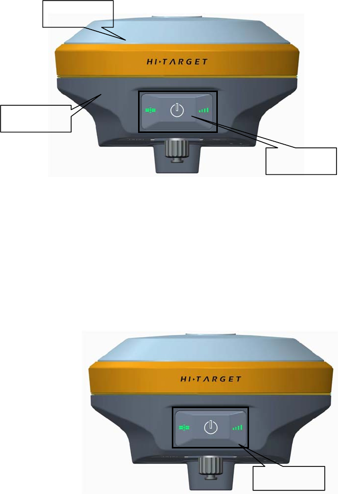
Receiver Appearance
The product appearance is divided into three sections,upper
cover, bottom cover and control panel.
Figure 2-1
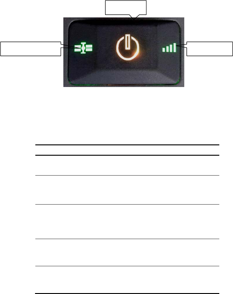
Control Panel
V90Plus middle frame for the control panel of the receiver, the control panel
includes a power switch button, a button to include all the features of V90Plus
receiver set. Three indicators, namely satellite lights, power light (bi-color
light), light (bi-color light).
Figure 2-2
upper cover
control panel
bottom cover
control panel
HI-TARGET 接收机介绍
12
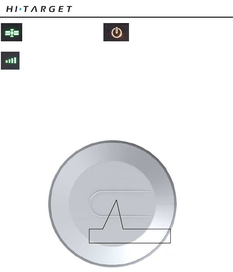
Satellite light (green light) status light (red and green light)
power light (red and green light)
Power Button Functions: Startup,shutdown,operating mode switching, the
mode switching confirmation status query, automatically set the base station,
forced shutdown, reset the board and so on.
Upper Cover
Figure 2-3
◇ U-Loss Prevention boss:U-boss can effective anti-wear;
◇ Color mode: appearance of the structure, Clear ,beautiful, drop
Bottom Cover
Including battery compartment, five-pin socket, speaker, Mini USB
interface.
U-Loss Prevention boss
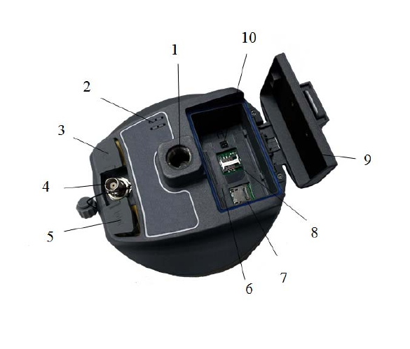
1- Screw connection 2- speaker 3-USB interface and protective plug 4-GPRS/
Antenna Interface 5- Five-pin plug socket and protection 6- Battery compartment 7-
SD card slot 8-SIM card slot 9- Battery Cover 10-SLC Power Block.
Figure 2-4
◇ connection screw: for the instrument fixed to the base or the pole.
◇ Trumpet: Real-time operation and status of the instrument voice
broadcast.
◇ USB interface: For connection to the host and external devices,
upgrade firmware and download the static data, can also be used as USB to
serial port using a special mode of operation (need to install drivers).
◇ 3G / GPRS internal radio antenna connection: Connect 3G / GPRS
antenna using the network, then the built-in UHF radio antenna when using the
radio.
8
HI-TARGET 接收机介绍
14
◇ Five-pin socket: For connection to the host and external data links
and external power source.
◇ battery compartment: for housing lithium batteries.
◇ SD card slot: SD card for housing, can store large-capacity static data.
◇ SIM card slot: for receiving USIM / SIM card for data link
communications and remote control.
◇ Battery cover: battery cover can dust and water, batteries and a host of
spare parts have protection role.
◇ SLC power base: lithium is used to connect with the host.
◇ Protective plug: socket for dust and waterproof.
Note: 1. If it is unnecessary to use five-core socket,
eight-core socket and difference antenna
interface, please cover the rubber plug to
prevent dust.
2. In case of inflowing, the trumpet may be
silent or hoarse, which will recover
normally after drying.
Batteries
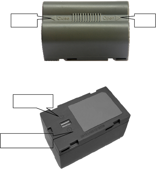
Figure 2-5
Figure 2-6
Environmental Requirements
The receiver shall operate in dry working environment regardless of
waterproof materials. In order to advance the stability and service cycle of
receiver, the receiver shall be prevented from extreme environment, such as:
◇ Moisture
◇ Temperatures above 65 degrees centigrade
◇ Below - 40 degrees centigrade
◇ Corrosive liquids or gases
Close Open
Positive pole
Negative pole

HI-TARGET 接收机介绍
16
Electronic Jamming
The receiver shall not be installed in the place near to strong electric power
and interference signal, such as:
◇ Oil duct (spark plugs)
◇ Generator
◇ Battery-operated motor cycle
◇ DC-AC power supply changeover equipment
◇ Signal transmitting station (tower)
◇ Power supply

Elementary Operation
This chapter describes:
■ Control panel
■ Function Key
■ Status Inquiry
■ LED Function
■ Start and stop receiver
■ Reset Motherboard
■ Automatic setting station
■ Static collection
■ Static data storage
■ RTK data storage
C
H
A
P
T
E
R
3

HI-TARGET
18
■ U disk data download
■ Firmware
■ Electronic bubble
■ Electronic bubble calibration
■ WiFi password settings
■ Power Supply System
■ Radio frequency settings
■ SIM card / USIM card
■ Micro SD Card
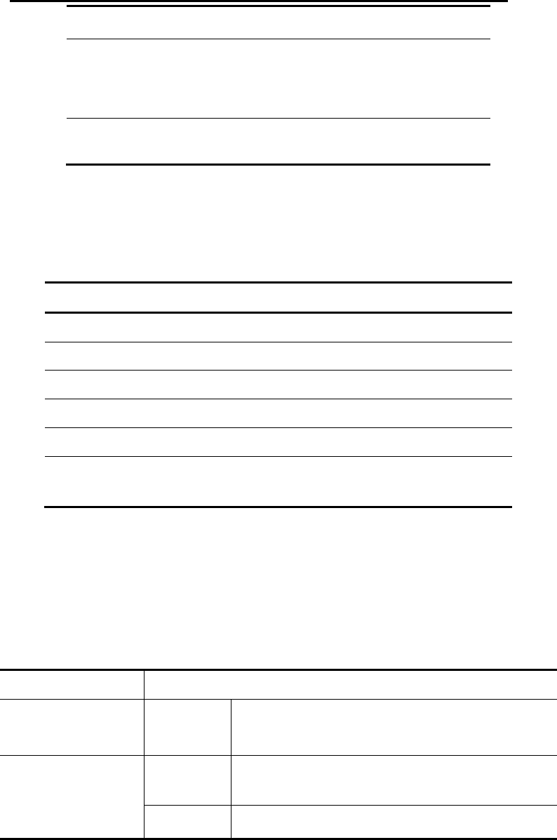
Control panel
Most settings and operations of receiver are completed using two keys on
control panel.
Figure 3-1
Function Key
Table 3.1 Description of keys operation time
Operation name Note
on Shutdown state, long press the button one
second boot
off Boot mode, three seconds ≤pressing the
button≤6 seconds, talking the first "buzz",
release the button, normal shutdown
Automatic setting
station
Shutdown mode, press the button six seconds
long, broadcast "is automatically set base
station", release the button, the instrument
will automatically set the base station
Operating mode
switching
Double-click the button to enter the operating
mode switching, double-click each time a
working mode switch
Operating mode
switching
confirmation
In operating mode switching process, click
the button to confirm
Satellite light
Power light
Status light
HI-TARGET
20
Status Inquiry See Schedule
Reset Motherboard The boot state, long press the button more
than 6 seconds, voice reporting second sound
"ding dong", release the button, reset
motherboard
Forced shutdown The boot state, long press the button more
than 8 seconds, forced shutdown
Status Inquiry
Table 3.2 Key Functions
Working status Broadcast content
GSM base GSM base
External base External base
WiFi base WiFi base
GSM rover GSM rover
External rover External rover
Static Static collection interval X,Elevation angle X,
Remaining storage is X,Satellites number X
LED Function
Different settings mode indicator displays the status of different, see
Appendix 3: Control panel lights.
Table 3.3 LED Function Description
Operating Meaning
Power Light
(Yellow)
Long-term
lighting
Normal voltage: the battery> 7.6V, foreign> 12.6V
Power Light
(Red)
Long-term
lighting
Normal voltage: 7.1V <internal battery ≤7.6V,
11V <foreign ≤12.6V
Slow flash Undervoltage:the battery ≤7.1V, foreign ≤11V

fast flash Tip Power: 1-4 flash per minute under the direction
of electricity
Signal light
(Status Green)
Off when you did not use GSM / WiFi client
Long-term
lighting
GSM / WiFi connected to the server
Slow flash GSM has landed on the 3G / GPRS network or
connect to WiFi hotspots
fast flash GSM is landing when prompted 3G / GPRS
networks or WiFi hotspots are connected
Data light
(Status Red)
Slow flash 1, the data link transmit and receive data (mobile
station to receive only tips, the base station only
prompt emission)
2, static data collection
Off Data link device mobile or base station is using can
not communicate, the communication module fails,
no data output
Satellite lights
(Green)
Long-term
lighting
Satellite lock
Slow flash Star Search or satellites are lost
Off 1, when resetting the receiver, motherboard failure,
no data output
2, static mode, motherboard failure, no data output
Reset the
motherboard, still
when an error occurs
(insufficient storage
space)
Three lights flash irregular
Start and Stop Receiver
Table 3.4 Description of display state of indicator under startup and
shutdown mode
Boot-s Press the All indicator Starting music, work mode before

HI-TARGET
22
trap power
button for
1 second
lights on previous startup and Voice prompt of data
link mode
Shutdo
wn
Long
press
power
button for
3 seconds
All indicator
lights off
Shutdown music
Reset motherboard
The boot state, long press the button more than 6 seconds, voice reporting
second sound "ding dong", release the button, reset the motherboard.
Auto set basestation
Shutdown mode, press the button six seconds long, broadcast "is
automatically set base station", release the button, the instrument will
automatically set the base station
Static collection
V90Plus receiver can be used for static measurements, setting method to
double-click the button to enter the operating mode switching, double-click
each time a working mode switch; in operating mode switching process, click
the button to confirm, set up after the success of the red status light interval
seconds (depending set the sampling interval to be) flashes once they capture
one epoch. Static measurements collected data is stored in host memory card
(when the host memory below 2M, automatically switches to an external SD
memory card). After the static data file must be downloaded to a computer for
processing a static post-processing software.
NOTE:Working mode switch: You can also switch by handheld, please
refer to the specific operation "Hi-Survey Software User's Guide"
→ equipment → Accessibility → static capture settings.
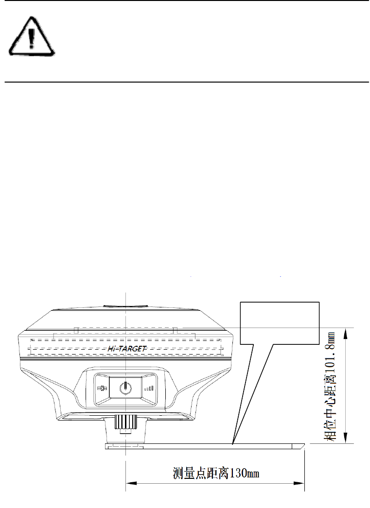
Static acquisition step
1. Set up the instrument at the measurement point, the point is to strictly,
and leveling.
2. Measure instrument height three times, each time not more than the
difference between 3mm, take the average as the ultimate instrument height.
High measuring instrument shall be measured to the center point mark stone
on top of the instrument of measurement reference member. V90Plus
receiver measuring reference member 0.130 m radius, phase center height
0.1018m.
figure 3-2
measurement
reference

HI-TARGET
24
3, the recording name, instrument number, instrument height, began
observing time.
4, boot, set the host to the static measurement mode. Satellite Blinking is
searching for satellites. Satellite into long bright lights from flashing status
indicates locked satellites. Status lights flash once every few seconds,
indicating that the acquisition of one epoch.
5, after the measurement is complete shutdown, shutdown time record.
6, download processing data.
Note :You can not move the base in the acquisition, acquisition
parameters can not be changed.
Static data storage
GNSS static data collection is stored in V90Plus receiver 16GB internal
memory in the "static" letter, effective storage space 14GB, a total of three
folders: log, gnss and rinex, log folder stores log information, gnss folder data
storage format is * .gns, rinex folder store data format as a standard RINEX
format data files. You can use the random configuration of USB data cable
connected to the computer, use the U disk operation mode to copy static data
to your
computer.
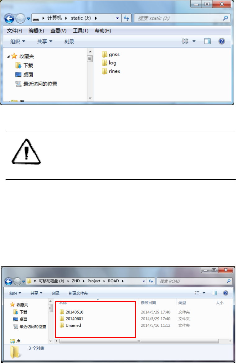
figure 3-3
Note:When the receiver inside and outside the storage space is less
than 2MB, data light (red state) flash, and will stop recording
data, the existing data files will not be overwritten.
RTK data storage
iHand20 handheld Haida V90Plus receiver can be connected via WiFi,
Bluetooth or network, when work began after the setup is complete, the
memory card handheld, you can book by hand random configuration data
cable data collected RTK RTK data storage downloaded onto your computer.
图3-4
Project Title
HI-TARGET
26
For more information about the hand-book, read "Hi-Survey Software
User's Guide."
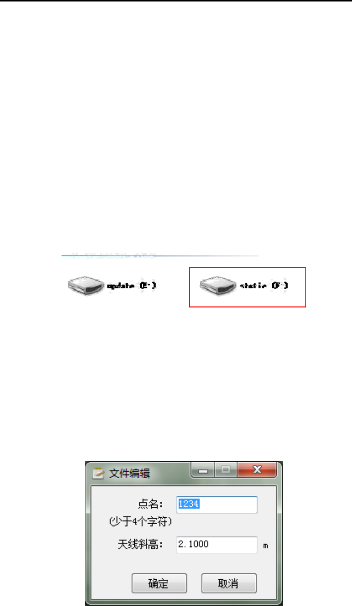
U disk data download
Receiver file management is stored by USB drive. It can be used upon
inserting and download by dragging directly without download programs. It
can only download static data and unable to write or read the receiver.
The receiver can download USB drive data with Y-type data cable, one
end is connected to computer USB and the other end is connected to eight-core
socket on bottom of receiver. After connection, “static” disk and SD card will
appear in computer. After opening the disk, it can copy the collected static file.
Figure 3-5
The steps to modify point name and antenna height of downloaded static
file are:
1. Choose *. GNS and double click the mouse.
2. Pop up the dialogue of “file edit” to modify point name and input antenna
height, and then click “ok”.
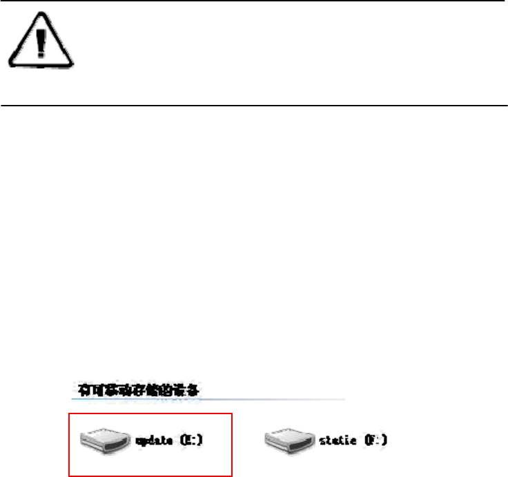
Figure 3-6
Note:the static files in removable disk can be deleted by GNSS
receiver management software rather than deleting
directly.
Firmware
The receiver uses the 3G network, the host firmware can be automatically
upgraded (You can refer to: "Hi-Survey Software User's Guide" →
equipment → Accessibility → receiver set) through the network, the user
can also choose to manually U disk upgrade.
The manually steps of host firmware upgrade
Figure 3-7
1, First need to open V90Plus receiver using a random configuration of
the USB cable to the computer USB port connection. At this point turn on my
computer, there will be "update" to upgrade the disk.
2, The host firmware (firmware can be downloaded from the official
website or obtained from the technician) copy to "update" to upgrade disk,
remove the U disk, unplug the cable, restart the receiver to complete the
upgrade.
3, Restart the success or failure of the upgrade process, there will be a

HI-TARGET
28
corresponding voice prompts to upgrade if the upgrade fails again or contact
technicians.
Electronic bubble
After Hi-Survey in demo mode, the built-in GPS or connect V90Plus,
support electronic bubble measuring software interface schematic display
electronic bubble position, the user can select the automatic collection in
electronic bubble automatic measurement and automatic sampling sites
according to the electronic bubble state. Electronic bubble has the following
states:
Good center: bubble-set within tolerance, the center is good;
Wait center: Wait a user to adjust the pole, so that the bubble is
centered;
Wait for measuring: Wait center 2S, measuring mode, sampling sites
were in this state;
Wait Move: After the completion of the first sampling point, waiting
for the user to move the pole, will start moving at once measure after a
certain distance;
Tilt overrun: bubble-set within tolerance, deviation from the center
position.
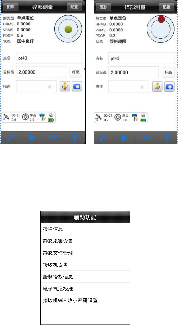
Figure 3-8 Figure 3-9
Electronic bubble calibration
When connecting V90Plus receiver, users can calibrate the electronic
bubble under the [Accessibility].
Figure 3-10
HI-TARGET
30
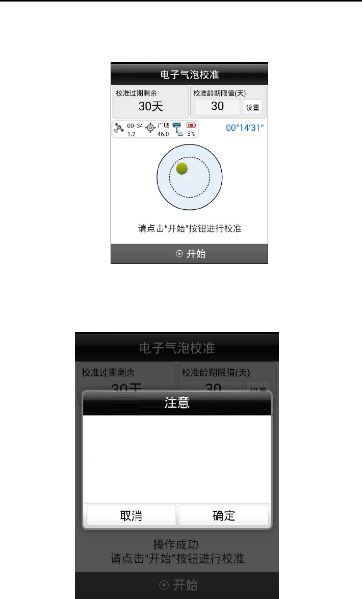
To do the following:
[Device] → [Accessibility] → [electronic bubble calibration]
Figure 3-11
V90Plus receiver placed outside the strict leveling base remain stationary
until the receiver locks satellite, ready when you are ready click on [Start]
button to bring up the calibration check box.
Figure 3-12
Keep the instrument in the strict
leveling base, do not move, so
that the satellite receiver
lock. When you are ready click
"
OK.
"
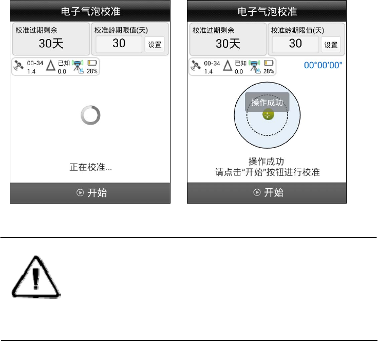
Click the pop-up confirmation box OK button, the hosts began to
calibrate the electronic bubble.
Figure 3-13 Figure 3-14
NOTE:Electronic bubble age calibration period recommended value is
set to 30 days, more than the set number of days without
calibration, the receiver will not work!
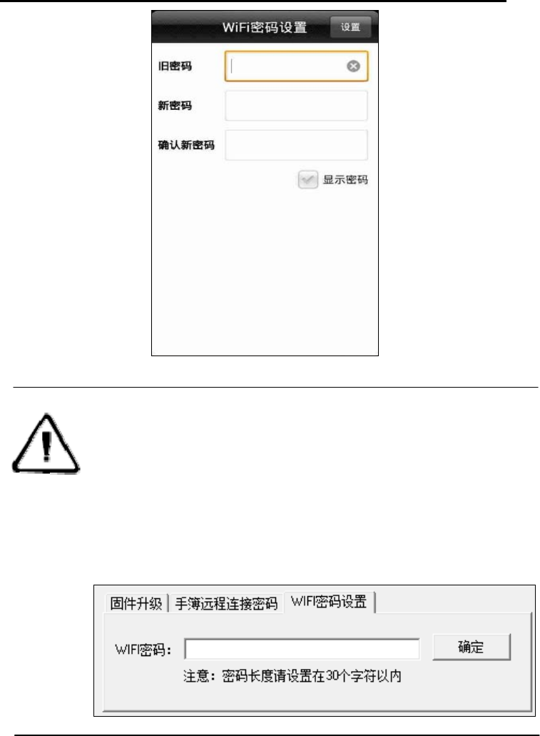
WiFi password setting
Set V90Plus host as a WiFi hotspot when connected to a password.
HI-TARGET
32
Figure 3-15
Note:1, WiFi factory default password See Schedule 3;
2. If you have forgotten your own set of WiFi password, you can "GNSS
receiver management software V1.4.2" → WiFi password, enter
the password and click OK to. Specific methods of operation
management software receiver, see: Annex 4.
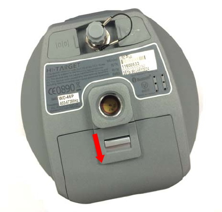
Power Supply System
Battery installation and removal
Installation
1, the battery cover and push back gently press the metal buckle.
Figure 3-16
2, the battery cover up to open the shells.
HI-TARGET
34
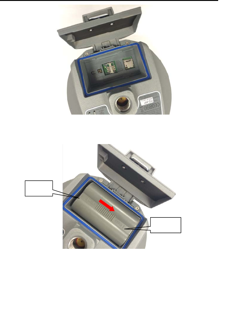
Figure 3-17
图3-18
3, toward the end of marked "Close" gently press and push (red arrow) can
complete the battery installation.
Remove:
Along with the name "Open" and hold the direction of launch, pour out
the battery,the battery complete uninstall.
Open
Close

Battery, charger
table 3.5, the battery charger model
Name Model
Lithium Battery BL-5000
Charger CL-8410/
CL-4400
HI-TARGET
36
Power supply
Table 3.6 Power Supply
powe
r
Power
supply
Lithium batteries; 5-pin external power
socket
Power
range
DC power supply: 6 ~ 28V
V90Plus receiver can also be powered via 5-pin socket bottom of the
main external power supply.
GSM mobile station external voltage range DC 6 ~ 28V, current is greater
than 3000 mA. When there is an external power supply, the host will
automatically detect the lithium battery and external power supply voltage,
select high voltage power supply. To use an external power supply, you must
use a dedicated power supply specified in Haida.
Note :1, the lithium battery time will be reduced as the temperature
and increase the number of charge and discharge
decreased use. Usually a new 5000 mAh lithium battery
do static data collection can be used 10 hours, so the
built-in network of the mobile station can be used for
eight hours, do 2W built-in radio transmitter base station
can be used for 7 hours.
2, in order to extend battery life, please charge the battery as soon as
possible within 24 hours after the battery runs out, otherwise
it will shorten battery life!
3. Long-term do not use batteries, please charge the battery once a
month to extend battery life.
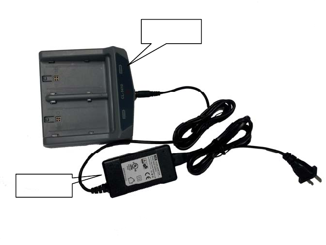
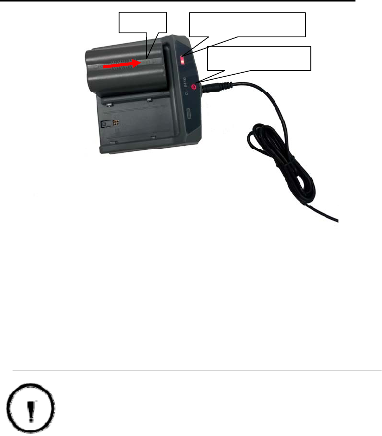
Charging
BL-5000 rechargeable lithium battery must use a dedicated CL-8410 /
CL-4400 lithium battery charger, charging time is about 7 hours. CL-8410
Battery Charger charging indicator light is red during charging, charging is
completed the light turns green, continue to charge 1 to 1.5 hours, then the
battery is fully charged.
Figure 3-19
Charging operation
1、Insert the battery charger in the following illustration
charger
adapter
HI-TARGET
38
Figure 3-20
2, along the "Close" direction, the red arrow shown in the figure above,
push the battery until it clicks.
3. After connecting the power, "charging indicator" is displayed as red
light is charging.
Caveat :1. Only use factory configuration of the battery and charger, do
not put the fire or short-circuited with a metal electrode.
2, in use, during charging, or storing the battery become heat, deformation,
leakage, emission of odor or other abnormal should stop using,
please replace the battery.
3, if the time is shortened, please stop using the battery, the battery is aging,
replace the battery.
SIM Card/USIM Card
V90Plus receiver supports SIM card and USIM card.
Table 3.7 SIM card / USIM card instructions
Close Charge indicator
Power Indicator
USIM
Card
WCDMA(ZHD/VRS)
GPRS(ZHD/VRS)
GSM
SIM
Card
GPRS(ZHD/VRS)
GSM
Installation card
Use V90Plus Receivers RTK jobs, you need to prepare SIM or USIM
card and open the corresponding data communication services. The required
number of cards, depending on your system configuration RTK survey. Each
host and each handheld for an installation card.
Whether the SIM card or USIM card has been launched 3G / GPRS
services, if China Mobile users, please contact customer service hotline 10086
China Mobile, China Unicom users, please contact customer service 10010
China Unicom, China Telecom, China Telecom users can consult customer
service 10000.
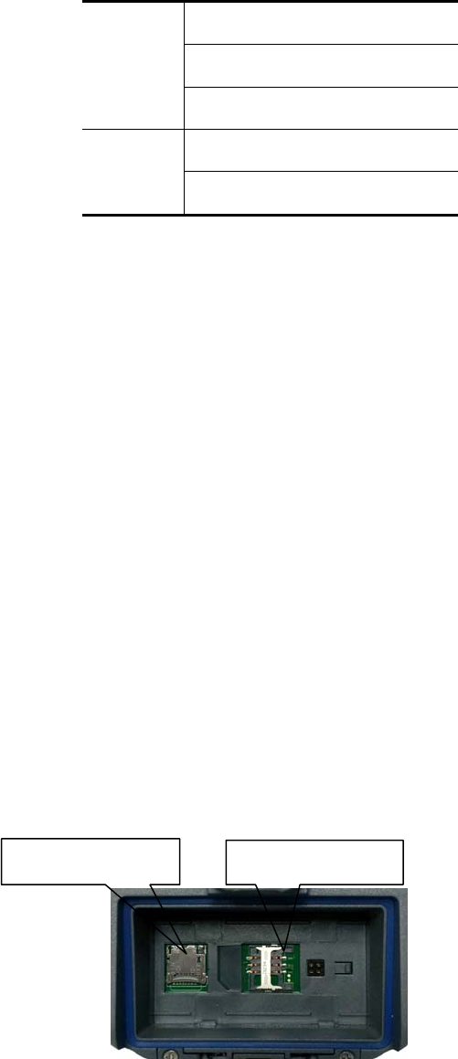
SIM card installation procedure is as follows:
1. Remove the battery cover, remove the battery to reveal the SIM card
slot.
Figure 3-21
SIM card slot
Micro SD card slot
HI-TARGET
40
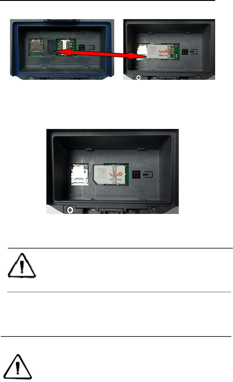
2, SIM card slot is consistent with the notch direction.
Figure 3-22
3, the SIM card in the deck, the front (with metal contact surface) down
into the slot.
Figure 3-23
4, the entire SIM card into the slot to complete the installation.
Note : Before installing the card you must turn off the receiver! If the
SIM card is installed in the boot state, the receiver will not
detect the SIM card, the mode setting is invalid!
Micro SD card
Micro SD card can store data collection and program files.
Note :Micro SD card (also known as TF card) for the small size
external memory expansion cards, commonly used in mobile
phones, PDA, note separately from normal SD card when you
buy zone configuration. Ordinary SD card Micro SD card
volume by volume to be large to fit V90Plus use. V90Plus
largest to 16GB Micro SD card.
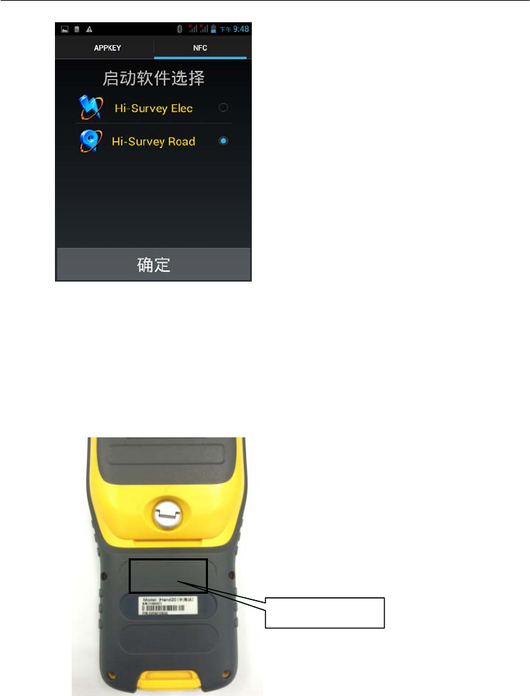
2. The iHand20 induction area close V90Plus sensing area, Hi-Survey
will automatically start V90Plus Bluetooth connection.
iHand20 located on the back of the sensing area:
V90Plus located atop the sensing area:
NFC sensor are
a

HI-TARGET
42
Technical parameters
This chapter describes:
■ GNSS section
■ Receiver Accuracy
■ Interface
■ Function keys and indicators
■ Physical Characteristics
■ Environment
C
H
A
P
T
E
R
4
GNSS Section
◇ GPS:Synchronous tracking L1
◇ BDS:Synchronous tracking B1、B2
◇ GLONASS:Synchronous tracking L1 C/A、L1 P、L2 C/A
◇ SBAS:Synchronous tracking L1 C/A、L5
◇ GIOVE-A:Synchronous tracking L1 BOC、E5A、E5B E5AltBOC
(Optional)
◇ GIOVE-B:Synchronous tracking L1 CBOC、E5A、E5B E5AltBOC
(Optional)
◇ GALILEO:(Upgrade Reserved)
◇ Initialization time Typically <10 seconds
◇ Initialization reliability> 99.9%
◇ 1Hz、2Hz、5Hz、10Hz、20Hz 和 50Hz Position output (default 1Hz)
◇ Difference Scheme Support:sCMRx、CMR、CMR+、RTCM 2.1、
2.2、2.3、3.0、3.1、3.2
◇ Navigation output format Support:ASCII:NMEA-0183 GSV、AV R 、
RMC、HDT、VGK、VHD、ROT、GGK、GGA、GSA、ZDA、VTG、
GST、PJT、PJK、BPQ、GLL、GRS、GBS
Receiver Accuracy
◇ Static, rapid static accuracy: Plane:±(2.5+1×10⁻⁶D) mm
Height:±(5+1×10⁻⁶D) mm
◇ RTK positioning accuracy:Plane:±(8+1×10⁻⁶D) mm

HI-TARGET
44
Height:±(15+1×10⁻⁶D) mm
Interface
◇ 1 x RS232 serial interface
◇ 1 x Mini USB interface
◇ 1 x SIM card interface
◇ 1 x SD card interface
◇ 1 x 3G / GPRS antenna interface
◇ 1 xBluetooth interface
◇ 1 x WiFi Interface
◇ 1 x Built-in lithium battery Interface
◇ 1 xFifth pin interface
Function keys and indicators
◇ 1 panels buttons: a power button on the receiver can be flexibly
various settings, and a sound, light work with
◇ 3 LEDs: a satellite LED (monochrome), a status light (color), a power
indicator light (color)
Physical Characteristics
◇ Core control chip CotexA8, built-in 16GB Flash memory
◇ Gravity acceleration sensor (electronic bubble)
◇ Vo l u m e : φ153mm×h83mm
◇ Weight: 1.0kg (without lithium battery)
◇ Anti-2 m natural drop, anti-two meters underwater temporary
immersion.
◇ Built-in 5000mAh high-capacity lithium-ion battery. Voltage: 7.4V, a
new battery continuous working time: 12 hours static, GPRS mode 9 hours,
2W station transmitting 7 hours.
◇ Can be an external DC power supply, wide input range 6 ~ 28V,
internal and external power supply automatically switches
Host Power (static mode): ≤3.5W
Environment
◇ Protection class:IP67
◇ Working temperature: -40 ℃ ~ 65 ℃, Storage temperature:-40℃~
75℃

附表 1 出产默认频率表
46
Socket and Main
Accessories
This chapter describes:
■ Preface
■ Five-pin socket
■ Five-wire
■ Mini USB interface
■ Mini USB wire
■ Antenna Interface
■ Antenna
C
H
A
P
T
E
R
5
Preface
The chapter will introduce the appearance and application of main interface of
receiver and accessories. The following equipment does not represent all users
purchased V90 Plus. According to different configurations, the specific
configuration shall be subject to the delivery order upon purchasing.
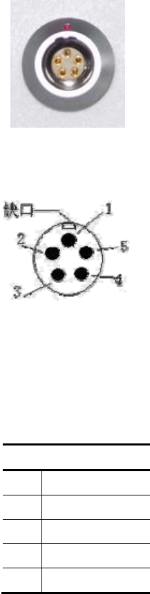
Five-pin socket
Figure 5-1
Figure 5-2
1,Five-pin socket:Also known as COM2/PW2,normally used to connect the host and
external data link connection, external power source.
Table5.1 five-pin socket Signal Description
Fifth-core signal
1 GND
2 GND
3 Vin
4 RXD
5 TXD
附表 1 出产默认频率表
48
2, All the companies are in circular socket counterclockwise positive start
numbering pin; pin round plugs are numbered starting with welding face
counterclockwise.
3,All the above data (TXD), the (RXD) signals to receivers explained.
TXD transmit data to the receiver signal line, RXD received data to a receiver
line.
4. In addition, the computer serial port DB9 pin connector signals: 2
(RXD computer data reception signal line), 3 (TXD computer data
transmission signal line), 5 (GND signal ground). Referred to as "2 receive 3
rounds."
Note:Above all when facing the host, the host at the bottom of the socket
front icon (ie plug weld surface).
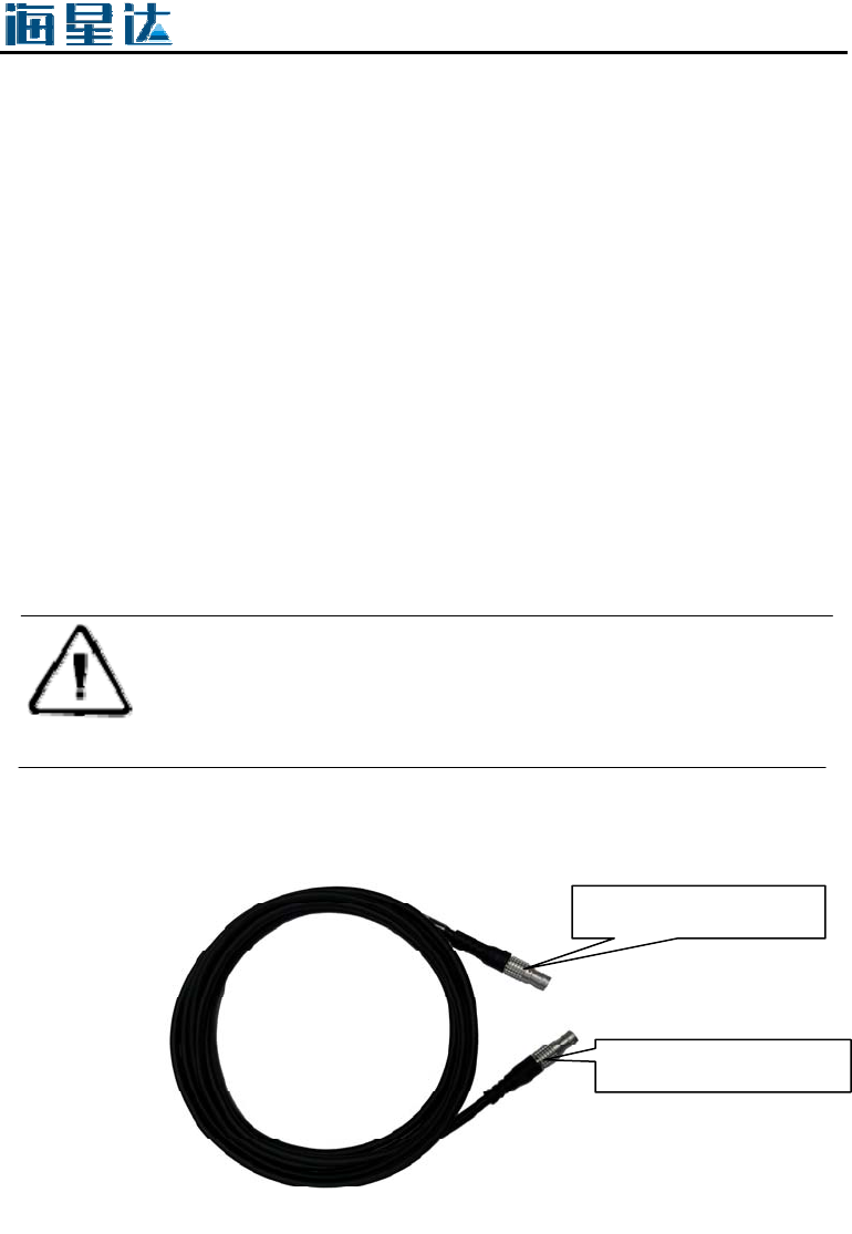
Five-wire
图5-3
Five-wire:V90Plus host and plug for connection to the radio, differential
data transmission;
five-pin socket
five-pin socket
Five-pin socket:For connecting the radio receiver and five-pin plug socket.
Figure 5-4
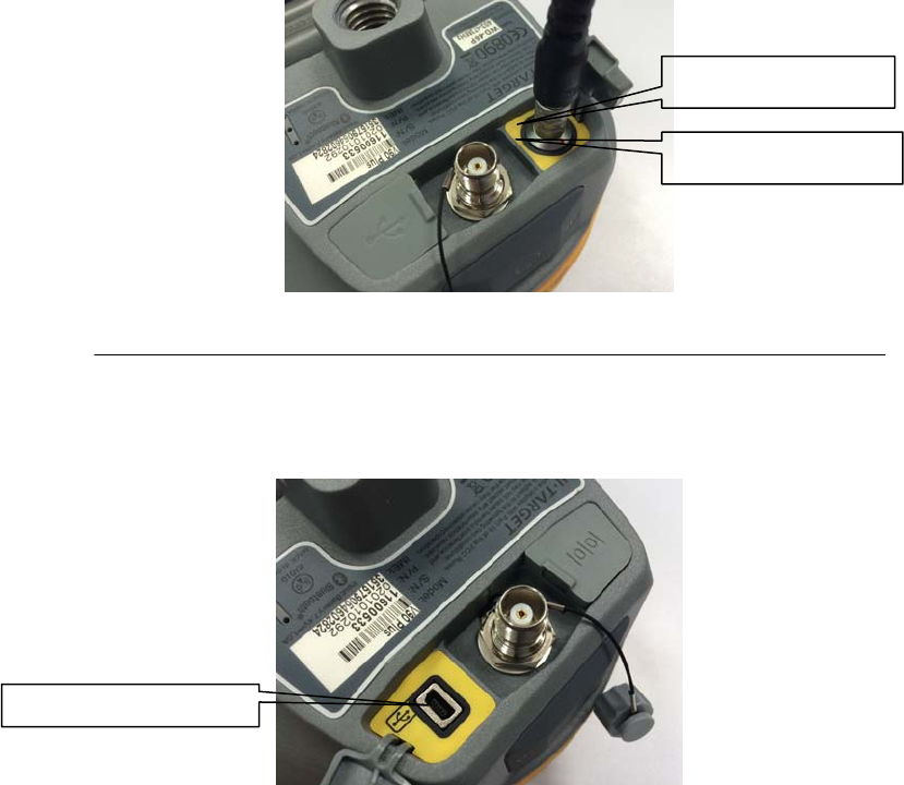
Mini USB Interface
Figure 5-5
For connection to the host and external devices, upgrade firmware and
download the static data, can also be used as USB to serial port using a special
mode of operation (need to install drivers, see Annex 4).
Mini USB cable
Plug the red dot
Socket red dot
Mini
US
B in
t
r
e
f
ace
附表 1 出产默认频率表
50
Figure 5-6
Mini USB cable, one end is a standard USB connector on one end and Mini
USB interfaces; an external device connected to the host for data
transmission.
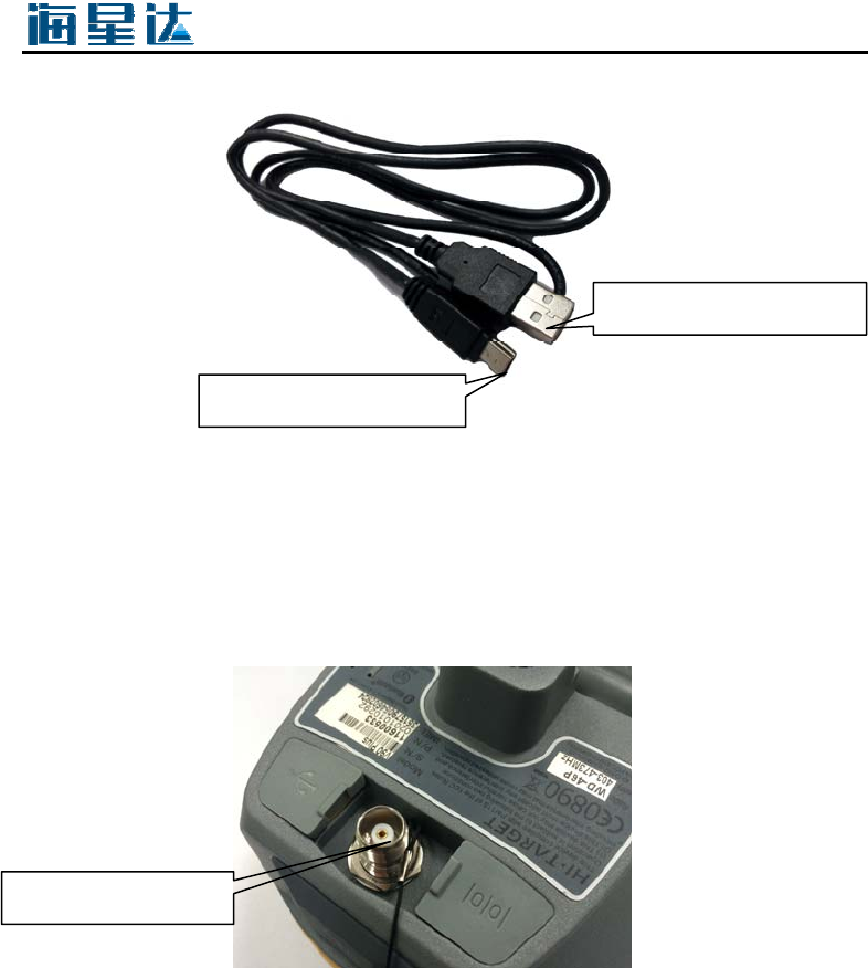
Antenna Interface
Figure 5-7
3G / GPRS radio antenna is built using the same antenna interface;
connection 3G / GPRS antenna using the network.
Mini USB interface
Standard USB interface
Antenna Interface

Schedule 2 control panel lights
Table 2 control panel lights illustrate
Operating Meaning
Power light
(yellow)
on Normal voltage: the battery> 7.6V, foreign> 12.6V
Power light
(red)
on Normal voltage: 7.1V <internal battery ≤7.6V, 11V
<foreign ≤12.6V
Slow
flash
Brown: the battery ≤7.1V, foreign ≤11V
Fast
flash
It indicates that the battery: Flash indicate the charge per
minute for 1 to 4
Signal light
(Status
Green )
off When not using GSM
on GSM connected to the server
Slow
flash
GSM indicates that landed on the 3G / GPRS network
Fast
flash
When the instructions are landing GSM 3G / GPRS
network
Data light
(Status Red)
Slow
flash
1, the data link transmit and receive data (mobile station to
receive only tips, the base station only prompt emission)
2, static data collection
Fast
flash
1, the error still occurs (less than FLASH memory space)
2, static files being uploaded
on Data link device mobile or base station is using can not
communicate, the communication module fails, no data
output
Satellite
lights
(Green)
on Satellite lock
Slow
flash
Star Search or satellites are lost
Fast
flash
Every minute or query when reporting a number of
satellites in the satellite lock case
off 1, when resetting the receiver, motherboard failure, no data
output
2, static mode, motherboard failure, no data output
附录
52
Schedule 4 USB virtual serial port
driver installation
1)First, it confirms that our equipment has been launched USB virtual
serial port functions. This step requires the use of the company's Android hand
book binding Hi-Survey software to view and set in the "Device" →
"Accessibility" → "Receiver Settings" → "USB Virtual Serial Port" →
"ON".
2)Check if the function is open, with a Micro USB cable to connect the
instrument and computer, install the driver. Win7 32bit system as an example
to demonstrate. After testing, the drivers support Win7 32bit, Win7 64bit,
Windows XP 32bit, other systems without making tests.
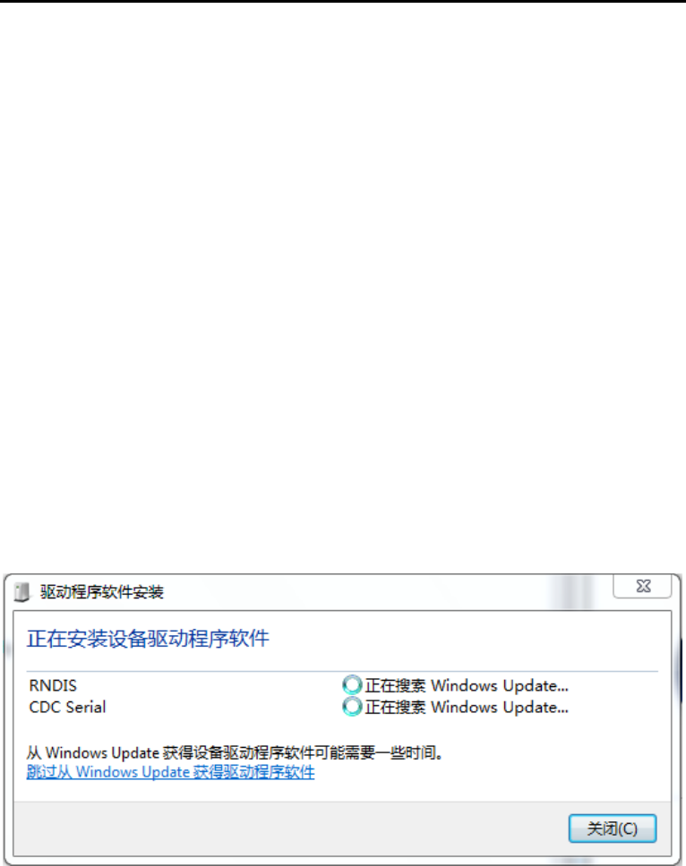
3)After connecting the cable, the system will prompt two devices need to
install drivers.
Figure 1
Now select "Skip obtaining driver software from Windows Update,"
because we need to manually install the driver. Failing such a prompt start
directly from step 4).
53
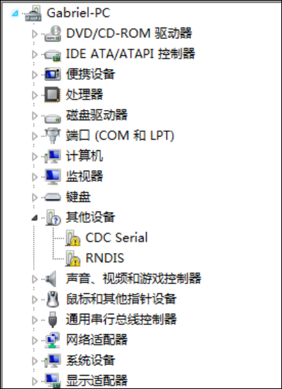
4)Open Systems "Device Manager" in the "other" option, you will see
two unidentified device. "CDC Serial" and "RNDIS".
Figure 2
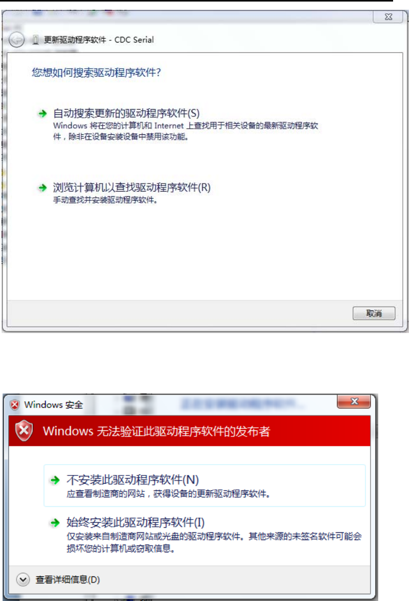
5)Click "CDC Serial", right-select "Update Driver Software" in the
pop-up window, select "Browse my computer for driver software (R)", then
select the file drivers "linux_cdc_seial.inf" where the folder directory, then
click "Next."
附录
54
Figure 3
6)If you search for a valid drive, pop occurs.
Figure 4
55
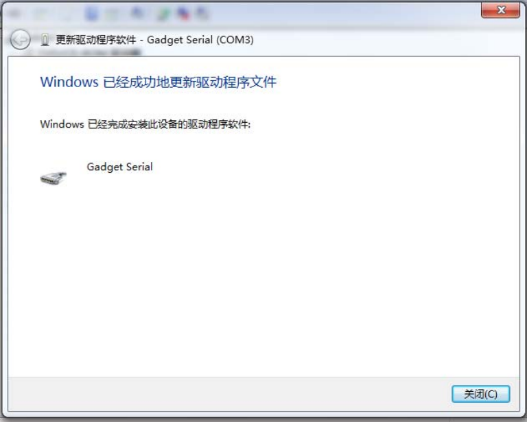
In this case, select the "Always install driver software." After a successful
installation displays the following information.
Figure 5
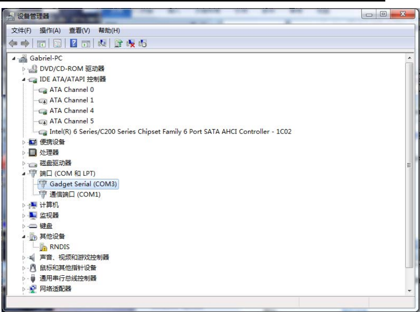
7)Then you can see the serial device, and serial number in the Device
Manager.
附录
56
Figure 6
Since we did not use to "RNDIS" device, so it can not install the driver.
57
FCC Caution: Any changes or modifications not expressly approved by the party
responsible for compliance could void the user's authority to operate this equipment.
This device complies with Part 15 of the FCC Rules. Operation is subject to the
following two conditions: (1) This device may not cause harmful interference, and (2)
this device must accept any interference received, including interference that may
cause undesired operation.
This device and its antenna(s) must not be co-located or operating in conjunction with
any other antenna or transmitter.
This equipment should be installed and operated with minimum distance 20cm
between the radiator and your body.
NOTE: This equipment has been tested and found to comply with the limits for a
Class B digital device, pursuant to Part 15 of the FCC Rules.
These limits are
designed to provide reasonable protection against harmful interference in a
residential installation. This equipment generates, uses and can radiate radio
frequency energy and, if not installed and used in accordance with the
instructions, may cause harmful interference to radio communications.
However, there is no guarantee that interference will not occur in a particular installation.
If this equipment does cause harmful interference to radio or television reception,
which can be determined by turning the equipment off and on, the user is
encouraged to
try to correct the interference by one or more of the followingmeasures:
-- Reorient or relocate the receiving antenna.
-- Increase the separation between the equipment and receiver.
-- Connect the equipment into an outlet on a circuit different from that to which the
receiver is connected.
-- Consult the dealer or an experienced radio/TV technician for help.