High Flying Electronics Technology HF-A21 HF-A21 User Manual GPON SFU System Design
High-Flying Electronics Technology Co., Ltd. HF-A21 GPON SFU System Design
User Manual
HF-A21 Embedded WiFi Module User Manual
Shanghai High-Flying Electronics Technology Co., Ltd
www.hi-flying.com
1
HF-A21
Embedded WiFi Module User Manual
V1.0
Overview of Characteristic
Support IEEE802.11b/g/n Wireless Standards
Support TCP/UDP/HTTP Network Protocols
Support UART/Ethernet Data Interface
Support Work As STA/AP/AP+STA Mode
Support Router/Bridge Mode Networking
Support Internal/External Antenna Option
Support AT+ Instruction Set for Configuration
Support Friendly Web Configuration Page
Support Heatbeat Signal
Support Smart Link Application Tools
Support UART Free/Auto-Frame Function
Single +3.3V Power Supply
Small Size: 25 x 40mm
FCC/CE Certificated

HF-A21 Embedded WiFi Module User Manual
Shanghai High-Flying Electronics Technology Co., Ltd
www.hi-flying.com
2
TABLE OF CONTENTS
1. PRODUCT OVERVIEW ............................................................................................................... 6
1.1. General Specification ............................................................................................................. 6
1.2. Hardware Introduction ............................................................................................................ 7
1.2.1. Pins Definition .................................................................................................................... 7
1.2.2. Mechanical Size ................................................................................................................. 9
1.2.3. On-board Chip Antenna ..................................................................................................... 9
1.2.4. External Antenna ............................................................................................................. 10
1.2.5. Evaluation Kit ................................................................................................................... 10
1.2.6. Order Information ............................................................................................................. 12
1.3. Hardware Reference Design ................................................................................................ 12
1.3.1. Hardware Typical Application .......................................................................................... 12
1.4. Typical Application ............................................................................................................... 13
2. PACKAGE INFORMATION ....................................................................................................... 14
5.1 Shipping Information ............................................................................................................ 14
APPENDIX A: EVB REFERENCE DESIGN ................................................................................... 15
APPENDIX B: CONTACT INFORMATION ..................................................................................... 16

HF-A21 Embedded WiFi Module User Manual
Shanghai High-Flying Electronics Technology Co., Ltd
www.hi-flying.com
3
LIST OF FIGURES
Figure 1. HF-A21 Appearance .............................................................................................................. 7
Figure 2. HF-A21 Pins Map .................................................................................................................. 7
Figure 3. HF-A21 Mechanical Dimension ............................................................................................. 9
Figure 4. HF-A11 Chip Antenna Keep Out Region............................................................................... 9
Figure 5. Suggested Module Placement Region ................................................................................ 10
Figure 6. HF-A21 Evaluation Kit ......................................................................................................... 11
Figure 7. HF-A21 Order Information ................................................................................................... 12
Figure 8. HF-A11 Hardware Typical Application ................................................................................ 12
Figure 9. Shipping Information ............................................................................................................ 14
LIST OF TABLES
Table 1 HF-A21 Module Technical Specifications............................................................................... 6
Table 2 HF-A21 Pins Definition ........................................................................................................... 7
Table 3 HF-A11 External Antenna Parameters ................................................................................. 10
Table 4 HF-A21 Evaluation Kit Interface Description ........................................................................ 11

HF-A21 Embedded WiFi Module User Manual
Shanghai High-Flying Electronics Technology Co., Ltd
www.hi-flying.com
4
HISTORY
Ed. V1.0 Created on 5-09-2016.
HF-A21 Embedded WiFi Module User Manual
Shanghai High-Flying Electronics Technology Co., Ltd
www.hi-flying.com
5
1. PRODUCT OVERVIEW
1.1. General Specification
Table 1 HF-A21 Module Technical Specifications
Class
Item
Parameters
Wireless
Parameters
Certification
FCC/CE
Wireless standard
802.11 b/g/n
Frequency range
2.412GHz-2.462GHz
Transmit Power
802.11b: +20 dBm (Max.)
802.11g: +18 dBm (Max.)
802.11n: +15 dBm (Max.)
Receiver Sensitivity
802.11b: -89 dBm
802.11g: -81dBm
802.11n: -71dBm
Antenna Option
External:I-PEX Connector
Internal:On-board PCB antenna
Hardware
Parameters
Data Interface
UART: 1200bps - 230400bps
Ethernet: 10Mbps/100Mpbs
GPIO,I2C
Operating Voltage
3.3V (+/-5%)
Operating Current
Avg:170mA Peak:400mA
Operating Temperature
-40℃- 85℃
Storage Temperature
-45℃- 125℃
Dimensions and Size
25×40×8mm
Software
Parameters
Network Type
STA /AP/AP+STA mode
Security Mechanisms
WEP/WPA-PSK/WPA2-PSK/WAPI
Encryption
WEP64/WEP128/TKIP/AES
Work Mode
Transparent Transmission
Serial command
AT+instruction set
Network Protocol
TCP/UDP/ARP/ICMP/DHCP/DNS/HTTP
Max. TCP Connection
32
User Configuration
Web Server+AT command config.
User Application SW
Support customized application SW
Provide SDK package
Provide smart link tools
HF-A21 Embedded WiFi Module User Manual
Shanghai High-Flying Electronics Technology Co., Ltd
www.hi-flying.com
6
1.2. Hardware Introduction
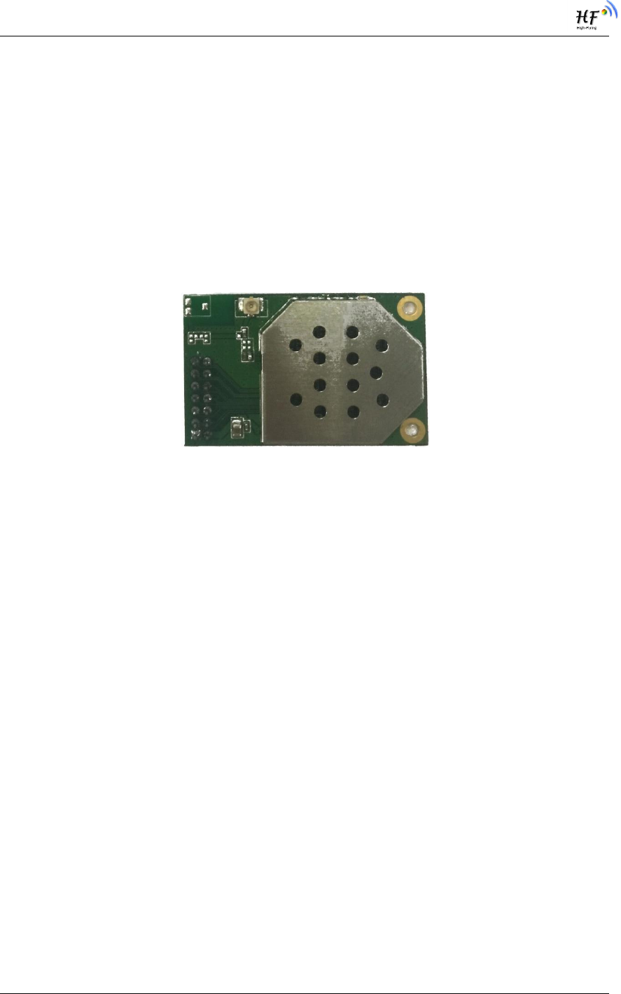
Figure 1. HF-A21 Appearance
1.2.1. Pins Definition
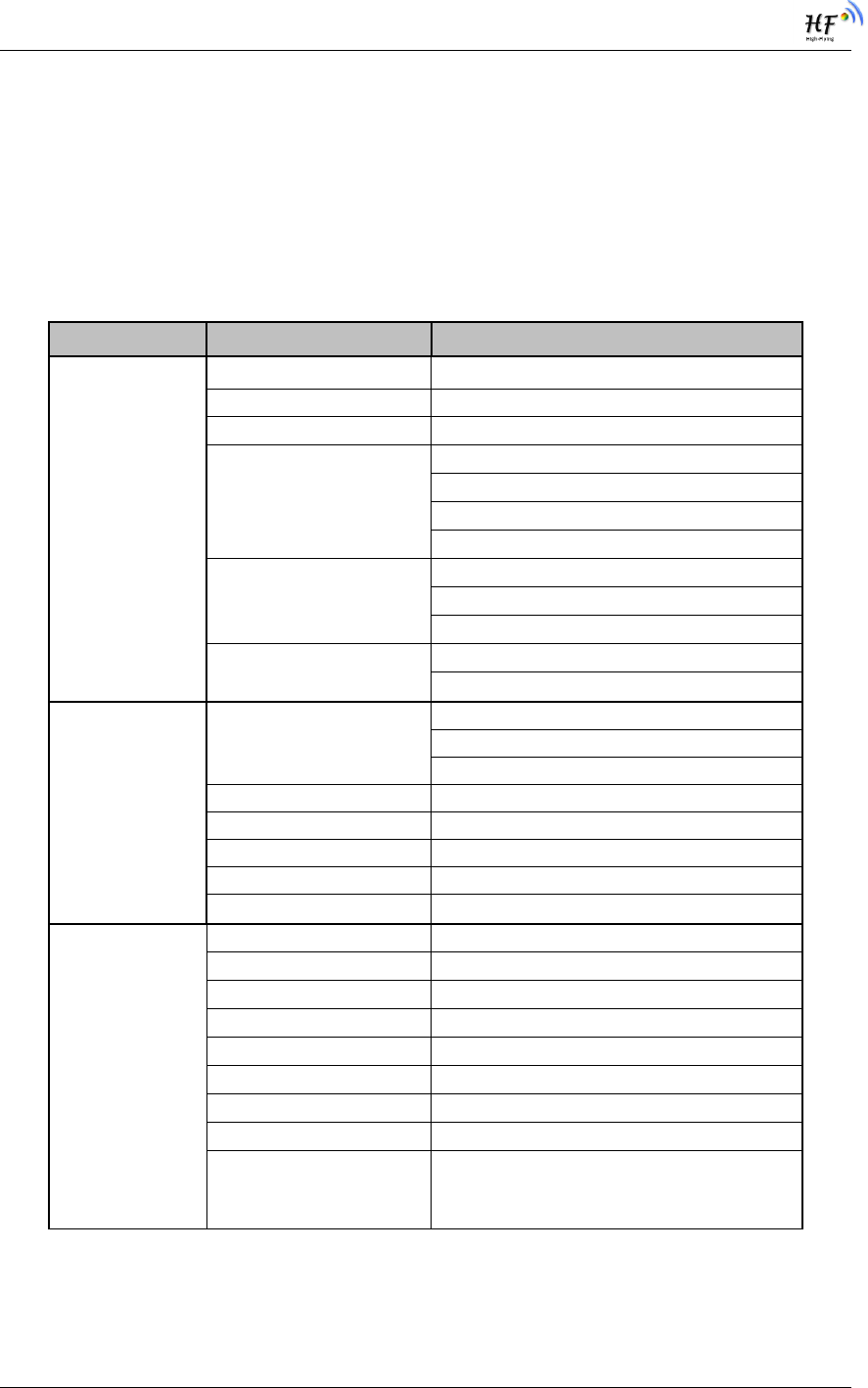
Figure 2. HF-A21 Pins Map
Table 2 HF-A21 Pins Definition
Pin
Description
Name
Direction
Note
1
Ground
GND
Power
2
VCC
3.3V
Power
3.3V @ 350mA power input
3
UART Data Transmit
UART_TXD
NOTE1
O
GPIO
GPIO12
I/O
4
UART Data Receive
UART_RXD
NOTE2
I
GPIO
GPIO13
I/O
5
GPIO
GPIO4
I/O
6
GPIO
GPIO5
I/O
7
Module reset signal
RESET
I
“Low ( 0 )” effective reset input.
The reset duration should be
kept more than 300ms
8
WiFi status Indication
nLink
O
“1”- WIFI connection available,
“0”- No WIFI connection
Can be configured as GPIO.
GPIO
GPIO0
I/O

HF-A21 Embedded WiFi Module User Manual
Shanghai High-Flying Electronics Technology Co., Ltd
www.hi-flying.com
7
9
Indicate the module
status of power on
process
nReady
O
“0” or “Palmodic Signal” - Finish
module boot up process;
“1” - Module boot up not finish.
Can be configured as GPIO.
GPIO
GPIO35
I/O
10
Restore configuration
nReload
I
Module will Restore factory
default configuration after set this
pin “0” more than 3s, then set
“1”.
GPIO
GPIO34
I/O
11
Ethernet Interface
PHY_RX+
I
Ethernet Data Interface, current
driver mode.
12
Ethernet Interface
PHY_RX-
I
13
Ethernet Interface
PHY_TX+
O
14
Ethernet Interface
PHY_TX-
O
Note1: These Pins should not add external pull-up resistor. It's configure pin for module
bootup. There is pull-down resistor for UART_TXD. This pin must keep low when bootup.
Note2: UART_RXD has a 4.7K pulldown resistor.
HF-A21 Embedded WiFi Module User Manual
Shanghai High-Flying Electronics Technology Co., Ltd
www.hi-flying.com
8
1.2.2. Mechanical Size
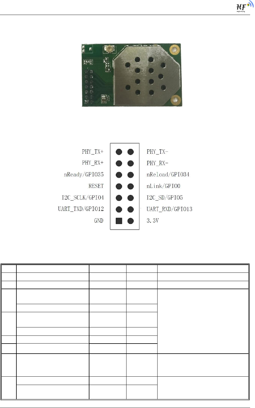
HF-A21 modules physical size as follows:
Figure 3. HF-A21 Mechanical Dimension
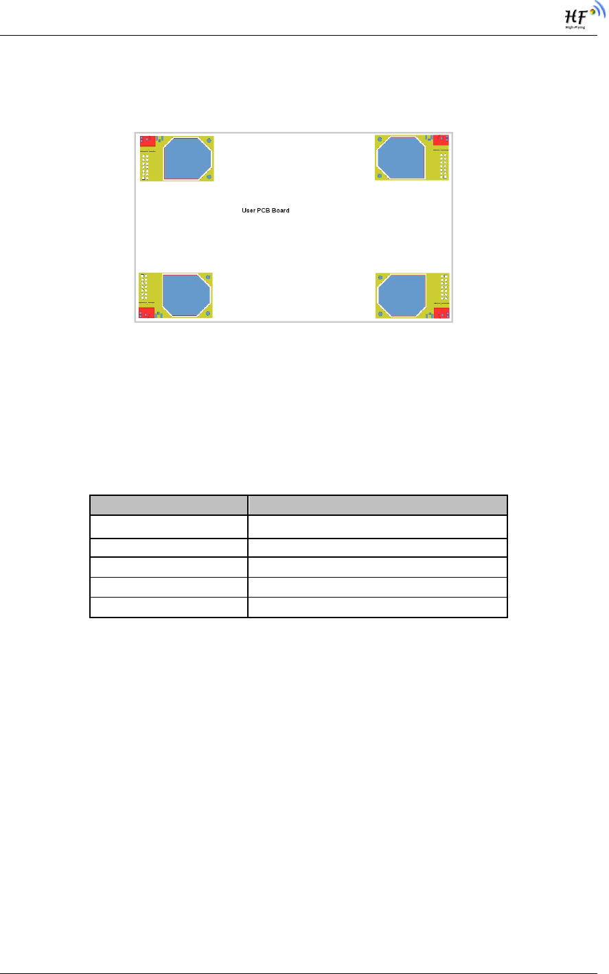
1.2.3. On-board Chip Antenna
HF-A11 module support internal ob-board chip antenna option. When costomer select internal
antenna, you shall comply with following antenna design rules and module location suggestions:
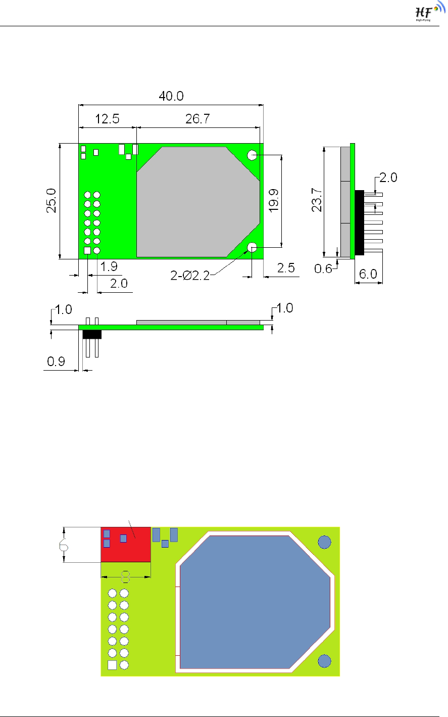
For customer PCB, RED color region (6x8mm) can’t put componet or paste GND net;
Antenna must away from metal or high components at least 10mm;
Antenna can’t be shieldedby any meal enclosure; All cover, include plastic, shall away
from antenna at least 10mm;
Figure 4. HF-A11 Chip Antenna Keep Out Region
HF-A21 Embedded WiFi Module User Manual
Shanghai High-Flying Electronics Technology Co., Ltd
www.hi-flying.com
9
High-Flying suggest HF-A11 module better locate in following region at customer board, which to
reduce the effect to antenna and wireless signal, and better consult High-Flying technical people
when you structure your module placement and PCB layout.
Figure 5. Suggested Module Placement Region
1.2.4. External Antenna
HF-A11 modules support internal antenna and external antenna option for user dedicated
application. If user select external antenna, HF-A11 modules must be connected to the 2.4G
antenna according to IEEE 802.11b/g/n standards.
The antenna parameters required as follows:
Table 3 HF-A11 External Antenna Parameters
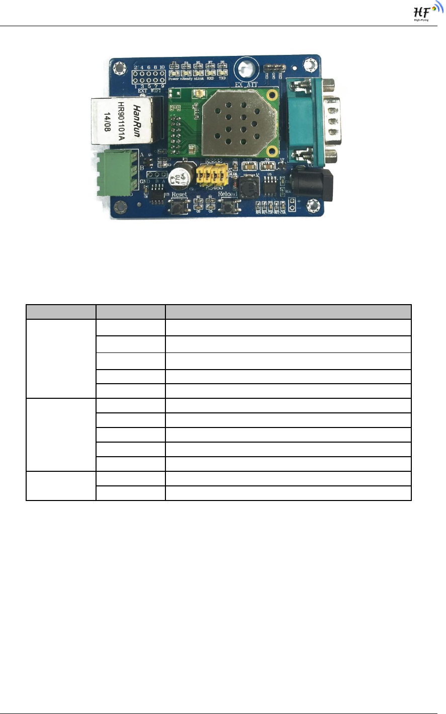
1.2.5. Evaluation Kit
High-Flying provides the evaluation kit to promote user to familiar the product and develop the
detailed application. The evaluation kit shown as below, user can connect to HF-A21 module with
the RS-232 UART port, 100M Eth port or Wireless port to configure the parameters, manage the
module or do the some functional tests.
Item Parameters
Frequency range 2.4~2.5GHz
Impedance 50 Ohm
VSWR 2 (Max)
Return Loss -10dB (Max)
Connector Type I-PEX or populate directly
HF-A21 Embedded WiFi Module User Manual
Shanghai High-Flying Electronics Technology Co., Ltd
www.hi-flying.com
10
Figure 6. HF-A21 Evaluation Kit
The external interface description for evaluation kit as follows:
Table 4 HF-A21 Evaluation Kit Interface Description
Function Name Description
External
Interface DC jack 5~18V power input connector
3-Pin 3-Pin RS485 interface(Reserved)
DB9 Male serial jack of 9-pin,and used to connect to PC
RJ-45 100M Eth Interface
Module 2x7 2mm DIP connector
LED Power (Red) 3.3V Power Indicator
TXD TXD Indicator
RXD RXD Indicator
Ready nReady/GPIO Indicator
Link nLink/GPIO Indicator
Button Reset Used to reset the module.
Reload Module restore to factory default configuration.
HF-A21 Embedded WiFi Module User Manual
Shanghai High-Flying Electronics Technology Co., Ltd
www.hi-flying.com
11
1.2.6. Order Information
Base on customer detailed requirement, HF-A21 series modules provide different variants and
physical type for detailed application.
Figure 7. HF-A21 Order Information
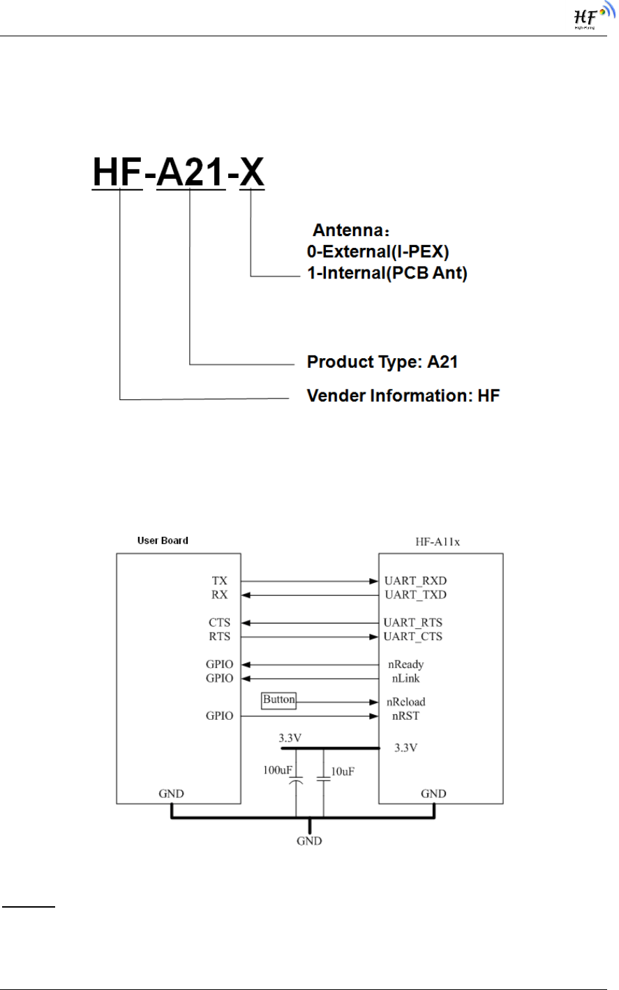
1.3. Hardware Reference Design
1.3.1. Hardware Typical Application
Figure 8. HF-A11 Hardware Typical Application
Notes:
nRST- Module hardware reset signal. Input. Logics “0” effective.
There is 100K Ohm pull-up resister internal. When module power up or some issue happened,
MCU need assert nRST signal “0” at least 300ms, then set” 1” to keep module fully reset.

HF-A21 Embedded WiFi Module User Manual
Shanghai High-Flying Electronics Technology Co., Ltd
www.hi-flying.com
12
nReady- Module boot up ready signal. Output. Logics “0” effective.
There is 4.7K Ohm pull-up resister internal. The module will output “0” “or “Palmodic Signal” after
normal boot up. This signal used to judge if module finish boot up and ready for application or
working at normal mode.
nLink- Module WIFI connection indication. Output.
There is 4.7K Ohm pull-up resister internal. When module connect to AP (STA mode) or some
WiFi STA connect to module (AP mode), the module will output “0”. This signal used to judge if
module already at WiFi connection status.
nReload- Module restore to factory default configuration.Input. Logics “0” effective.
User can assert nReload signal “0” more than 3’s through button or MCU pin, then release,
module will restore to factory default configuration and re-start boot up process. User need add
4.7K~10K Ohm pull-up resister external the module. If not use this function, then can use AT
command AT+FRLDEN=off to disable it.
UART_TXD/RXD- UART port data transmit and receive signal.
1.4. Typical Application
Refer to HF-A21-SMT user manual for detailed application and module usage.
HF-A21 Embedded WiFi Module User Manual
Shanghai High-Flying Electronics Technology Co., Ltd
www.hi-flying.com
13
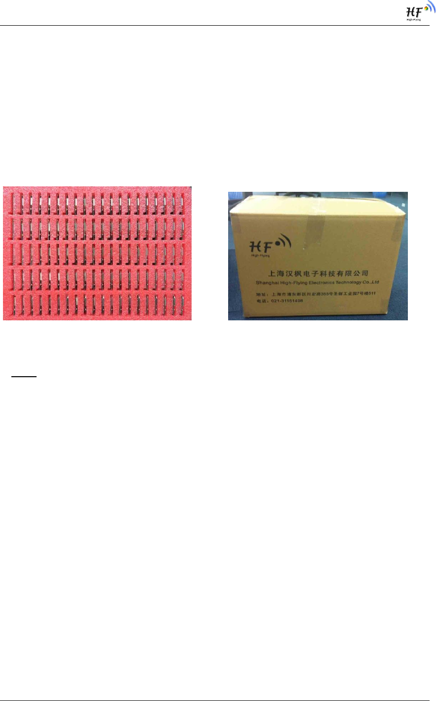
2. PACKAGE INFORMATION
5.1 Shipping Information
TRAY BOX
Size: 370*270*40 mm Size: 370*270*160 mm(inside)
Figure 9. Shipping Information
Note:
1 tray = 100pcs
1 box = 4 trays = 4 * 100 pcs = 400pcs
HF-A21 Embedded WiFi Module User Manual
Shanghai High-Flying Electronics Technology Co., Ltd
www.hi-flying.com
14
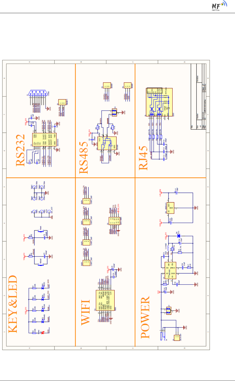
APPENDIX A: EVB REFERENCE DESIGN

HF-A21 Embedded WiFi Module User Manual
Shanghai High-Flying Electronics Technology Co., Ltd
www.hi-flying.com
15
APPENDIX B: CONTACT INFORMATION
------------------------------------------------------------------------------------------------------------
Address: Room 1002,Building 1,No.3000,Longdong Avenue,Pudong New
Area,Shanghai,China, 201203
Web: www.hi-flying.com
Service Online: 400-189-3108
Mail Contact: sales@hi-flying.com
-----------------------------------------------------------------------------------------------------------

HF-A21 Embedded WiFi Module User Manual
Shanghai High-Flying Electronics Technology Co., Ltd
www.hi-flying.com
16
FCC STATEMENT
1. This device complies with Part 15 of the FCC Rules. Operation is subject to the following
two
conditions:
(2) This device must accept any interference received, including interference that may cause
undesired operation.
NOTE: This equipment has been tested and found to comply with the limits for a Class B
digital
device, pursuant to Part 15 of the FCC Rules. These limits are designed to provide
reasonable
protection against harmful interference in a residential installation.
This equipment generates uses and can radiate radio frequency energy and, if not installed
and
used in accordance with the instructions, may cause harmful interference to radio
communications.
However, there is no guarantee that interference will not occur in a particular installation. If
this
equipment does cause harmful interference to radio or television reception, which can be
determined by turning the equipment off and on, the user is encouraged to try to correct the
interference by one or more of the following measures:
Reorient or relocate the receiving antenna.
Increase the separation between the equipment and receiver.
Connect the equipment into an outlet on a circuit different from that to which the receiver is
connected.
Consult the dealer or an experienced radio/TV technician for help.
FCC Radiation Exposure Statement
(1) This device may not cause harmful interference, and
Changes or modifications not expressly approved by the party responsible for
compliance could void the user's authority to operate the equipment.
Warning:
This equipment complies with FCC radiation exposure limits set forth for an uncontrolled environment.
This equipment should be installed and operated with minimum distance 20cm between the radiator &
your body

HF-A21 Embedded WiFi Module User Manual
Shanghai High-Flying Electronics Technology Co., Ltd
www.hi-flying.com - -
Antenna Specification:
Type: Chip Antenna
Brand: High-Flying
Gain: 2.0dBi
17
FCC INFORMATION (additional)
OEM INTEGRATION INSTRUCTIONS:
This device is intended only for OEM integrators under the following conditions: The module must be
installed in the host equipment such that 20 cm is maintained between the antenna and users, and the
transmitter module may not be co-located with any other transmitter or antenna. The module shall
be only used with the internal antenna(s) that has been originally tested and certified with this
module. As long as 3 conditions above are met, further transmitter test will not be required.
However, the OEM integrator is still responsible for testing their end-product for any additional
compliance requirements required with this module installed (for example, digital device emissions, PC
peripheral requirements, etc.).
Validity of using the module certification:
In the event that these conditions cannot be met (for example certain laptop configurations or
co-location with another transmitter), then the FCC authorization for this module in combination
with the host equipment is no longer considered valid and the FCC ID of the module cannot be used
on the final product. In these circumstances, the OEM integrator will be responsible for re-evaluating
the end product (including the transmitter) and obtaining a separate FCC authorization.
End product labeling:
The final end product must be labeled in a visible area with the following: “Contains FCC ID:
2ACSVHF-A21”.
Information that must be placed in the end user manual:
The OEM integrator has to be aware
not to provide information to the end user regarding how to install or remove this RF module in
the user's manual of the end product which integrates this module. The end user manual shall
include all required regulatory information/warning as show in this manual.
Model: HF-A21

HF-A21 Embedded WiFi Module User Manual
Shanghai High-Flying Electronics Technology Co., Ltd
www.hi-flying.com - 18 -
END OF DOCUMENT
© Copyright High-Flying, May, 2011
The information disclosed herein is proprietary to High-Flying and is not to be used by or disclosed to unauthorized persons
without the written consent of High-Flying. The recipient of this document shall respect the security status of the information.
The master of this document is stored on an electronic database and is “write-protected” and may be altered only by
authorized persons at High-Flying. Viewing of the master document electronically on electronic database ensures access to
the current issue. Any other copies must be regarded as uncontrolled copies.