High Flying Electronics Technology HF-BL100-CU HF-BL100-CU User Manual GPON SFU System Design
High-Flying Electronics Technology Co., Ltd. HF-BL100-CU GPON SFU System Design
User Manual
HF-BL100-CU Low Energy Bluetooh(BLE 4.0)Module User Manual
Shanghai High Flying Electronics Technology Co., Ltd www.hi-flying.com - 1 -
HF-BL100-CU
Bluetooth Low Energy(BLE 4.0) Module
User Manual
V 1.2
Overview of Characteristic
Support IEEE 802.15.1 BT4.0 Wireless Standard
Support wireless upgrade (OTA)
UART Transparent Transmit Module
Supper low sleep mode power 1.3uA,excellence power save scheme
Unique stop mode, 60nA power
Support internal antenna
Single 1.9V~5.5V power supply
Smallest size : 22.8mm x 15.4mm x 2mm
ROHS compliance

HF-BL100-CU Low Energy Bluetooh(BLE 4.0)Module User Manual
Shanghai High Flying Electronics Technology Co., Ltd www.hi-flying.com - 2 -
Table of Contents
LIST OF FIGURES ..................................................................................3
LIST OF TABLES ...................................................................................6
1. PRODUCT OVERVIEW .........................................................................9
1.1. General Description ........................................................................9
1.2. Device Feature .............................................................................8
1.3. Key Application ............................................................................9
1.4. Device Parameter ........................................................................ 10
1.5. Order Information .........................................................................9
2. HARDWARE INTRODUCTION .............................................................. 12
2.1. Pin Definition ............................................................................. 12
2.2. Electrical Specification .................................................................. 14
2.3. Mechanical Size .......................................................................... 17
2.4. Antenna Layout .......................................................................... 17
3. UART TRANSAPARENT TRANSMIT MODE ............................................... 18
3.1. Transparent Transmit Mode ............................................................ 19
3.2. Transparent Transmit Pin Definition ................................................... 21
3.3. Factory Default Parametet ............................................................. 21
3.3.1. Device Name ............................................................................ 22
3.3.2. Broadcast Parameter ................................................................... 21
3.3.3. Transmit Power ......................................................................... 21
3.3.4. Connect Parameter ..................................................................... 23
3.3.5. Baudrate ............................................................................... 23
3.3.6. Send Latency parameter .............................................................. 22
4. UART AT COMMAND DEFINITION ...................................................... 23
4.1. Module Operation Mode Configure ..................................................... 23
4.2. AT:Command Overview ................................................................. 23
4.2.1. Command Format ....................................................................................................................... 25
4.2.2. Command List ............................................................................................................................. 26
4.3. AT Command ............................................................................. 27
4.3.1. Help Command........................................................................................................................... 28
4.3.2. Set Module NAME .................................................................................................................. 27
4.3.3. Query Module NAME ............................................................................................................. 28
4.3.4. Set Connect Parameter ......................................................................................................... 28
4.3.5. Query Connect Parameter .................................................................................................... 29
4.3.6. Set Baudrate ............................................................................................................................ 31
4.3.7. Query Baudrate ......................................................................................................................... 30
4.3.8. Reserved ..................................................................................................................................... 31
4.3.9. Get MAC Address .................................................................................................................... 31
4.3.10. Query Software Version ....................................................................................................... 31

HF-BL100-CU Low Energy Bluetooh(BLE 4.0)Module User Manual
Shanghai High Flying Electronics Technology Co., Ltd www.hi-flying.com - 3 -
4.3.11. Set Transmit Power ............................................................................................................ 31
4.3.12. Query Transmit Power ....................................................................................................... 32
4.3.13. Set Broadcast Parameter ................................................................................................. 33
4.3.14. Query Broadcast Parameter ............................................................................................ 34
4.3.15. Set User-define Broadcast Data ................................................................................... 34
4.3.16. Query User-define Broadcast Data ............................................................................. 35
4.3.17. Set Auto-Broadcast Switch ............................................................................................. 35
4.3.18. Query Auto-broadcast Switch ........................................................................................ 35
4.3.19. Start Broadcast .................................................................................................................... 37
4.3.20. Stop Broadcast ...................................................................................................................... 36
4.3.21. Query Current BLE Subsystem Status ....................................................................... 37
4.3.22. Disconnect .............................................................................................................................. 39
4.3.23. Set Device Verify Code ..................................................................................................... 38
4.3.24. Query Device Verify Code .................................................................................................. 39
4.3.25. Set UART Output Data Latency ................................................................................... 39
4.3.26. Save Parameter ..................................................................................................................... 41
4.3.27. Module Restore ...................................................................................................................... 41
4.3.28. Set Module Operate Mode ............................................................................................... 41
4.3.29. Reserved.................................................................................................................................. 42
4.3.30. Reserved.................................................................................................................................. 42
4.3.31. Reserved.................................................................................................................................. 42
4.3.32. Reserved.................................................................................................................................. 42
4.3.33. Module BLE Subsystem Status Notification .............................................................. 42
4.3.34. Module CPU Status Notification .................................................................................... 42
4.3.35. Restore Factory Setting via AT Command ..................................................................... 43
4.3.36. Enable Module Deep Sleep .................................................................................................. 43
4.3.37. Restore Facotry Setting via Hardware Method ......................................................... 44
4.3.38. Reserved.................................................................................................................................. 44
5. Read Electricity ............................................................................. 45
5.1. Read Eectricity Channel configuration (temporarily unavailable.) .................... 45
5.2. Electricity Data Description ............................................................ 45
6. APPLICATION OTA ......................................................................... 46
6.1. OTA Channel Configure .................................................................. 46
6.2. OTA Data Description ................................................................... 46
7. APP COMMAND .............................................................................. 47
7.1. Channel and Data Description ........................................................... 47
7.2. Data Format .............................................................................. 48
7.3. Command Content ........................................................................ 49
7.3.1. Command Type:0x0E .............................................................................................................. 48
7.3.2. Command Type:0x0F ............................................................................................................ 48
8. Basic Communication Mechanism............................................................ 50
8.1. Application Service Data Channel(User-define application service UUID:0x2B00) ....... 50

HF-BL100-CU Low Energy Bluetooh(BLE 4.0)Module User Manual
Shanghai High Flying Electronics Technology Co., Ltd www.hi-flying.com - 4 -
8.1.1. Module->APP, UART Data Channel【Feature UUID:0x2B10】 ....................................... 50
8.1.2. APP->Module,UART Data Channel【Feature UUID:0x2B11】 ...................................... 51
8.1.3. APP->Module,OTA Mode Switch【Feature UUID:0x2B12】 ....................................... 51
8.1.4. APP->Module,APP Command Channel【Feature UUID:0x2B13】 ................................. 51
8.2. Battery Service Data Channel .......................................................... 52
8.2.1. APP->Module,Battery Data Channel【Feature UUID:0x2A19】 ................................. 52
8.3. OTA Service Data Channel .............................................................. 52
8.3.1. APP->Module,OTA Data Channel ......................................................................................... 52
9. TEST .......................................................................................... 54
9.1. Test Transparent Transmit Function .................................................. 53
9.2. Test Battery Electricity Read .......................................................... 55
9.2.1. Electricity Read Command ............................................................ 55
9.2.2. Electricity Display .................................................................... 54
9.3. OTA Function Test ...................................................................... 55
9.3.1. Get Module firmware Version ......................................................... 55
9.3.2. Switch to OTA mode .................................................................. 55
9.3.3. OTA .................................................................................... 55
10. PACKAGE INFORMATION ................................................................ 56
10.1. Reflow Soldering Profile .............................................................. 56
10.2. Handling Instruction ................................................................... 56
10.3. Shipping Information ................................................................... 57
APPENDIX A: UART TRANSPARENT TRANSMIT TYPICAL APPICATION ........... 58
APPENDIX B: MODULE SCHEMATIC ........................................................ 60
APPENDIX C: EVK SCHEMATIC .............................................................. 62
APPENDIX D: CONTACT INFORMATION .................................................. 64

HF-BL100-CU Low Energy Bluetooh(BLE 4.0)Module User Manual
Shanghai High Flying Electronics Technology Co., Ltd www.hi-flying.com - 5 -
LIST OF FIGURES
Figure 1. HF-BL100-CU Order Information ............................................................................................. 10
Figure 2. HF-BL100-CU Pin Definition ....................................................................................................... 11
Figure 3. HF-BL100-CU Mechanical Size ................................................................................................. 16
Figure 4. HF-BL100-CU PCB Antenna Position ......................................................................................... 17
Figure 5. HF-BL100-CU Module Reference Placement ......................................................................... 17
Figure 6. Basic HF-BL100-CU Wireless Network Structure ............................................................... 18
Figure 7. HF-BL100-CU Default UART Parameter ................................................................................. 23
Figure 8. ”AT:HELP” List All Command ...................................................................................................... 24
Figure 9. Module UART Output Data Latency set Map .................................................................... 40
Figure 10. Module UART Receive Enable Data Map .............................................................................. 44
Figure 11. APP Scan & Connect Interface .............................................................................................. 53
Figure 12. APP Receive notify Interface ................................................................................................ 54
Figure 13. MCU Receive write Data Interface ...................................................................................... 54
Figure 14. Reflow Soldering Profile ....................................................................................................... 56
Figure 15. Package Information ................................................................................................................ 58
Figure 16. UART Transparent Transmit Typical Application ......................................................... 58
Figure 17. HF-BL100-CU Module Schematic(一) .............................................................................. 60
Figure 18. HF-BL100-CU EVK TOP VIEW(二) ................................................................................... 60
Figure 19. HF-BL100-CU EVK BOTTOM VIEW(三) ......................................................................... 61
Figure 20. EVK power and USB to UART Circuit(一) .................................................................... 62
Figure 21. EVK Interface Circuit (二) ............................................................................................... 62
Figure 22. EVK Interface Circuit(三) ................................................................................................ 63
LIST OF TABLES
Table 1 HF-BL100-CU Module Technique Specification ........................................................................... 9
Table 2 HF-BL100-CU Pin Function Definition ........................................................................................... 11
Table 3 Limited Specification ...................................................................................................................... 13
Table 4 Electrical Specification .................................................................................................................. 13
Table 5 RF Specification ............................................................................................................................... 14
Table 6 Work Mode and System Status .................................................................................................... 14
Table 7 AD Convertor Function Module DC Parameter Map .................................................................. 15
Table 8 Module Connect Interval 20ms Communication Mode Example ........................................... 20
Table 9 Error Code List ................................................................................................................................ 25
Table 10 AT Command List ........................................................................................................................... 25
Table 11 Command Data from APP to Module ........................................................................................... 47
Table 12 Feedback Data from Module to APP........................................................................................... 47
Table 13 Command Type 0x0F Command List ............................................................................................ 48

HF-BL100-CU Low Energy Bluetooh(BLE 4.0)Module User Manual
Shanghai High Flying Electronics Technology Co., Ltd www.hi-flying.com - 6 -
Table 14 Command Type 0x0F Feedback List ............................................................................................ 49
Table 15 Description of User-define Service of All Channnel .......................................................... 50
Table 16 0x2B10 Feature UART module->APP Channel Description ................................................ 50
Table 17 0x2B11 Feature UART APP->module Channel Dexcription ............................................... 51
Table 18 0x2B12 Feature OTA Mode Switch Channel Description ................................................. 51
Table 19 0x2B13 Feature APP Command Channel Descritpion ........................................................... 51
Table 20 Description of Battery Service of All Channel ..................................................................... 52
Table 21 0x2A19 Feature Battery Channel Description ...................................................................... 52
Table 22 Description of OTA Service of All Channel ......................................................................... 52
Table 23 00060001-F8CE-11E4-ABF4-0002A5D5C51B Feature OTA Data Channel Description52
Table 24 Reflow Soldering Specification .................................................................................................. 56

HF-BL100-CU Low Energy Bluetooh(BLE 4.0)Module User Manual
Shanghai High Flying Electronics Technology Co., Ltd www.hi-flying.com - 7 -
History
V1.0 08-25-2015. First Version
V1.1 09-01-2015. Update OTA and Add Battery service
V1.2 10-30-2015. Update APP AT Command format.

HF-BL100-CU Low Energy Bluetooh(BLE 4.0)Module User Manual
Shanghai High Flying Electronics Technology Co., Ltd www.hi-flying.com - 8 -
1. PRODUCT OVERVIEW
1.1. General Description
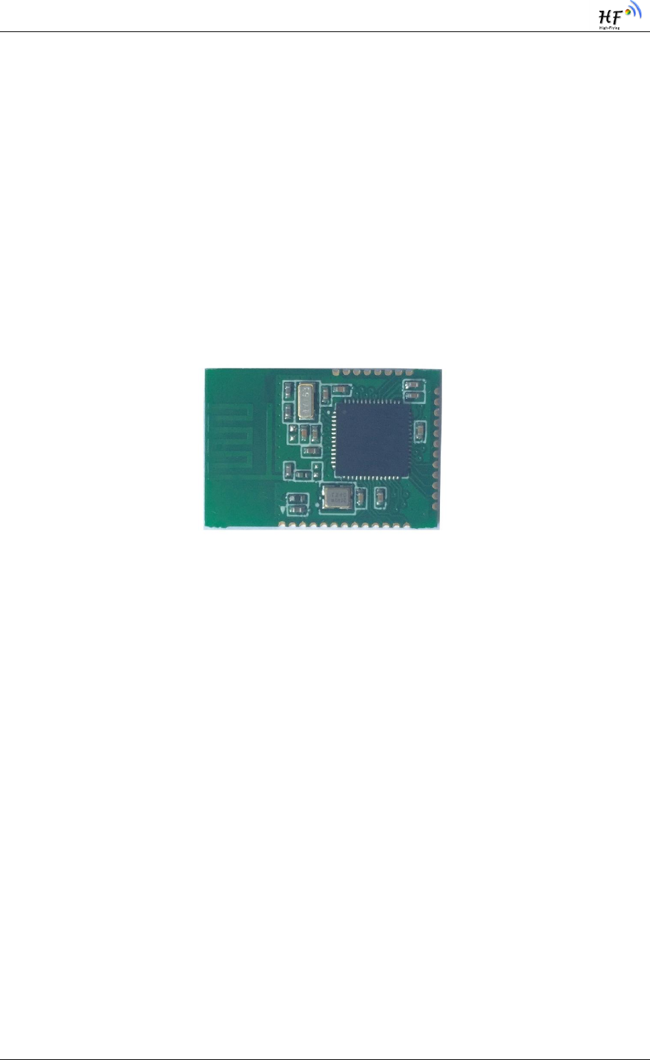
HF-BL100-CU Bluetooth Low Energy module is a high performance IOT module designed by High
Flying. It is based on Cypress chip, and provide a solution for connecting things to Bluetooth
wireless network and data transmit ting via UART interface. With the feature of low power,
small size, high anti-interference performance, the module integrates PCB antenna and use open
stamp type interface which enable customer have more flexibility on software and product
structure , and solve the RF hardware design and debug issue.
1.2. Device Feature
Smallest size: 22.8mm x 15.4mm x 2mm
With 32 bit high performance RISC 48MHz ARM M0 MCU,MCU build-in 16KB SRAM
and 128KB Flash;
1.9V~5.5V Single power supply
Support low power & multiple level power management mode
Full peripheral
GPIO interface
Serial Communication(UART application)
ADC interface
FCC/CE/BQB
ROHS compliance
1.3. Key Application
Smart LED lighting
Smart toy
Electronic Scale
Smart Cup
Smart Home Appliance
OBD
IOT, Smart Home Automation
Sports, fitness, consumer electronics products
Smart instrument, data acquisition ,sensor
PC、Tablet peripheral

HF-BL100-CU Low Energy Bluetooh(BLE 4.0)Module User Manual
Shanghai High Flying Electronics Technology Co., Ltd www.hi-flying.com - 9 -
1.4. Device Parameter
Table 1 HF-BL100-CU Module Technique Specification
Power details refer to Table 6
1.5. Order information
As per customer demand, HF-BL100-C can provide variant physical version, detail part
number as below:
Class
Item
Condition
Parameter
Wireless
paramete
r
Certificate
Wireless
standard
802.15.1
Frequency
range
2.402GHz-2.480GHz
Data rate
1Mbps@2.4GHz
Tx power
Max=+3 dBm,Min=-18dBm
Rx
sensitivity
-89 dBm
Hardwar
e
paramete
r
Data
interface
UART
GPIO
ADC
Operating
voltage
1.9~5.5V
BLE
Subsystem
current
Tx power=0 dBm,Tx
peak current
15.6mA
Rx peak current
16.4mA
Tx power=0 dBm,
broadcast interval=1s
18.9uA
Tx power=0 dBm,
connect interval=1s
18.9uA
CPU
Subsystem
current
Run
850uA+260uA*per MHz
Sleep ,@3MHz
1.1mA
Deep sleep
1.3uA
hibernate
150nA
Stop
60nA
Work
temperature
-40℃- 85℃
Storage
temperature
-45℃- 125℃
Size
22.8mm x 15.4mm x 2mm

HF-BL100-CU Low Energy Bluetooh(BLE 4.0)Module User Manual
Shanghai High Flying Electronics Technology Co., Ltd www.hi-flying.com - 10
-
HF-BL100-CU
Part number
CU->UART
Module Version
BL100->Bluetooth BLE Single mode
Company name
HF->Hi-Flying
Figure 1. HF-BL100-CU order information
HF-BL100-CU Low Energy Bluetooh(BLE 4.0)Module User Manual
Shanghai High Flying Electronics Technology Co., Ltd www.hi-flying.com - 11
-
2. HARDWARE INTRODUCTION
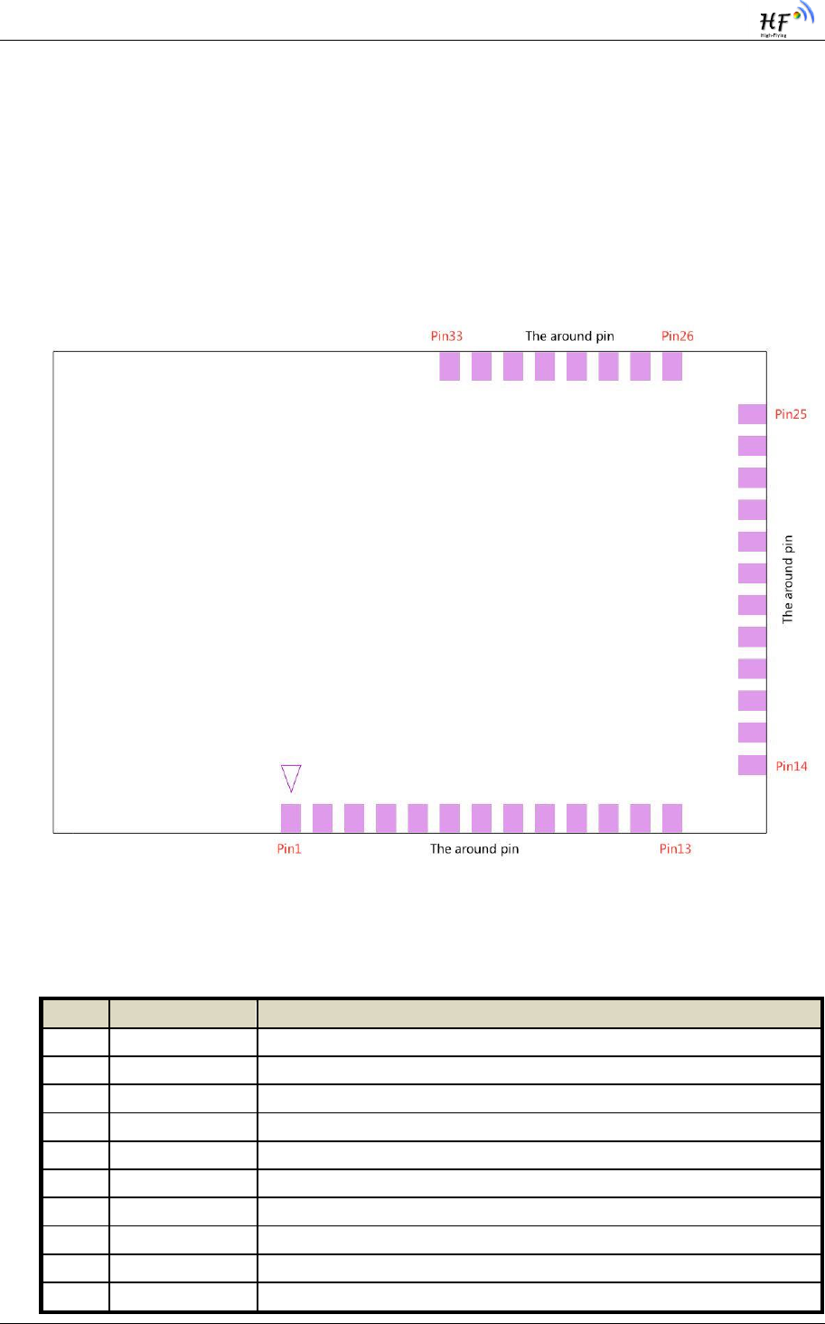
2.1. Pin Definition
TOPVIEW
Figure 2. HF-BL100-CU Pin Definition
Table 2 HF-BL100-CU Pin Function Definition
Pin
Net name
Description
1
GND
Ground
2
NC
NC
3
XRES
Module reset
4
SWCLK
SWD clock interface, firmware burn
5
SWDATA
SWD data interface, firmware burn
6
NC
NC
7
NC
NC
8
NC
NC
9
NC
NC
10
NC
NC

HF-BL100-CU Low Energy Bluetooh(BLE 4.0)Module User Manual
Shanghai High Flying Electronics Technology Co., Ltd www.hi-flying.com - 12
-
11
NC
NC
12
NC
NC
13
NC
NC
14
NC
NC
15
NC
NC
16
NC
NC
17
NC
NC
18
NC
NC
19
VBAT
+1.9V~+5.5V module power input
20
NC
NC
21
NC
NC
22
NC
NC
23
NC
NC
24
NC
NC
25
NC
NC
26
ADC0
Analog input
27
NC
NC
28
BCTS
BCTS(module send advanced signal data, wake external MCU)
29
MANUFACTURE
Restore factory setting
30
UART_TX
UART send data
31
UART_RX
UART receive data
32
WAKEUP
Enable system deep sleep & wake up STOP mode
33
GND
Module ground
HF-BL100-CU Low Energy Bluetooh(BLE 4.0)Module User Manual
Shanghai High Flying Electronics Technology Co., Ltd www.hi-flying.com - 13
-
2.2. Electrical Specification
Table 3 Limited Specification
Parameter
Description
Min
Value
Typ.
Value
Max
value
Unit
VDDD_ABS
Analog, digital, or radio supply
relative to VSS (VSSD = VSSA)
-0.5
-
6
V
VCCD_ABS
Direct digital core voltage input
relative to VSSD
-0.6
-
1.95
V
VGPIO_ABS
Maximum current per GPIO
-25
-
25
mA
IGPIO_injection
GPIO injection current, Max for
VIH > VDDD, and Min for VIL <
VSS
-0.5
0.5
mA
ESD_HBM
Electrostatic discharge human
body model
2200
V
LU
Pin current for latch up
-200
200
mA
Storage temperature
-45
125
°C
Max solder temperature
IPC/JEDEC J-STD-020
260
°C
Table 4 Electrical Specification
Parameter
Condition
Min
Value
Typ.
Value
Max
Value
Uni
t
Work voltage
1.9
3.3
5.5
V
BLE Subsystem
Tx peak current
Tx power =0DB
15.6
mA
Rx peak current
16.4
mA
Broadcast mode average
current
Tx power =0DB,broadcast
interval=1s
18.9
uA
Connect mode current
Connect power=0DB,connect
interval=1s
18.9
uA
CPU application
subsystem
Operate mode
System clock=48Mhz
(algorithm:0.85+0.26*48)
13.4
mA
System clock =24Mhz
7.1
mA
System clock=12Mhz
4
mA
System clock=6Mhz
2.5
mA
System clock=3Mhz
1.7
mA
Sleep mode
Run at 3Mhz
1.1
mA
Deep sleep mode
ECO stop,WCO work
1.3
uA
Stop mode
ECO stop , WCO work
60
nA

HF-BL100-CU Low Energy Bluetooh(BLE 4.0)Module User Manual
Shanghai High Flying Electronics Technology Co., Ltd www.hi-flying.com - 14
-
Table 5 RF specification
Parameter
Condition
Min value
Typ.
Value
Max value
Unit
Rx sensitivity
-89
dBm
Frequency
offset
tolerance
225
250
275
KHz
Frequency drift
-50
50
KHz
In-Band
blocking
rejection
2 MHz offset
-20
dB
>=3 MHz offset
-30
dB
Output power
0
3
dBm
Standard
frequency
2400
2482
MHz
Frequency
tolerance
±50
Ppm
Signal strength
accuracy
±5
dBm
Signal accuracy
1
dBm
Signal sampling
interval
6
uS
Channel band
2
MHz
Effective data
rate
1
Mbps
Table 6 Work Mode and System Status
Work mode
Current
Code run
External
digital
module
Extern
al
analog
module
Clock
sour
ce
Wakeup
source
Wake
up
time
Active
850uA+260u
A per MHz
Yes
All
All
All
-
-
sleep
1.1mA at
3MHz
No
all
All
All
Any
interrupt
source
0
Deep sleep
1.3uA
No
WDT, LCD,
I2C/SPI,
Link-Layer
POR,
BOD
WCO
, ILO
GPIO,
WDT,
I2C/SPI
Link
Layer
25uS
hibernate
150nA
No
No
POR,
BOD
No
GPIO
2mS
stop
60nA
No
No
No
No
WAKEUP
,XRES
2mS

HF-BL100-CU Low Energy Bluetooh(BLE 4.0)Module User Manual
Shanghai High Flying Electronics Technology Co., Ltd www.hi-flying.com - 15
-
Table 7 AD Convertor Module DC Parameter Map
Parameter
Description
Min.
value
Typ.
value
Max
value
Unit
Remark
A_RES
Resolution
-
-
12
bits
-
A_CHNIS_S
Number of channels
– single-ended
-
-
1
-
1 full speed
A-MONO
Monotonicity
-
-
-
-
YES
A_ISAR
Current
consumption
-
-
1
mA
A_VINS
Input voltage range
– single-ended
VSS
-
VDDA
V
A_INRES
Input resistance
-
-
2.2
kΩ
A_INCAP
Input capacitance
-
-
10
pF
VREFSAR
Trimmed internal
reference to SAR
-1
-
1
%
Percentage of Vbg
(1.024 V)
HF-BL100-CU Low Energy Bluetooh(BLE 4.0)Module User Manual
Shanghai High Flying Electronics Technology Co., Ltd www.hi-flying.com - 16
-
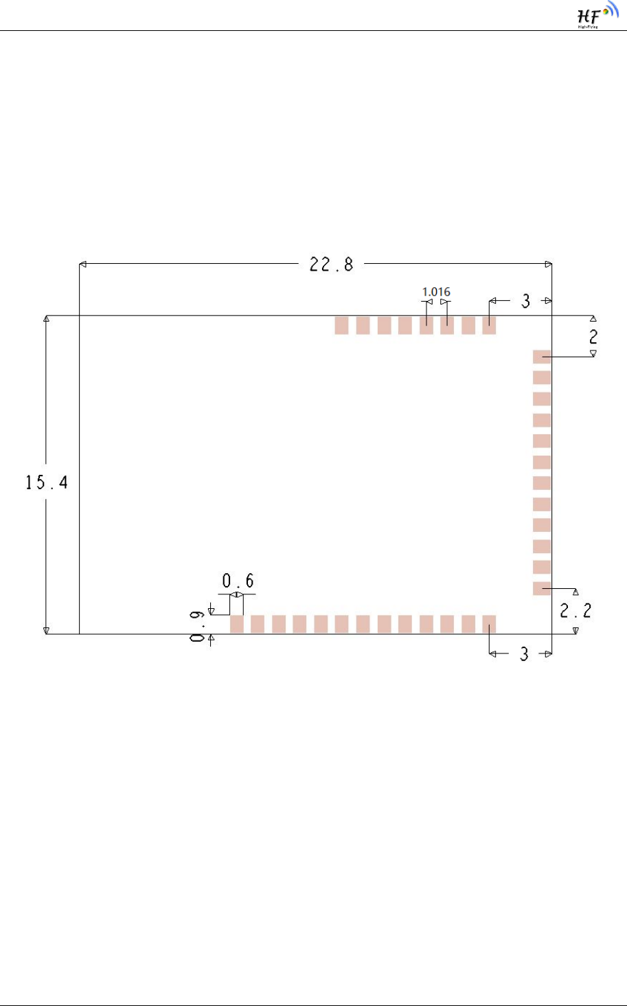
2.3. Mechanical size
HF-BL100-CU physical size (unit: mm)as below:
Module pad:size 22.8mm X 15.4mm ,pad space 1mm。
Figure 3. HF-BL100-CU Mechanical size
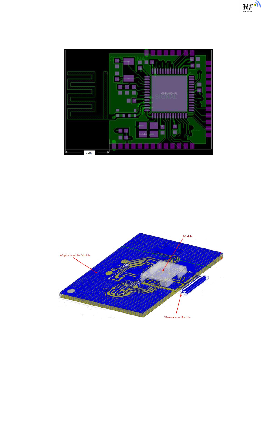
2.4. Antenna Layout
HF-BL100-CU support internal antenna. Antenna layout refer to Figure 4. Customer need to
obey following antenna design rules and module location suggestions:
For user PCB, place module on the edge area of the PCB as possible, or suspend the
antenna area.
Module antenna(22.8mmx7mm)correspondent area can‟t put components or paste
GND, the surrounding components or GND should be as far as possible from antenna
place.
HF-BL100-CU Low Energy Bluetooh(BLE 4.0)Module User Manual
Shanghai High Flying Electronics Technology Co., Ltd www.hi-flying.com - 17
-
Antenna must away from high components at least 10mm
Antenna can‟t be shielded by any metal enclosure.
Figure 4. HF-BL100-CU PCB antenna position
High Flying suggest to locate HF-BL100-CU as Figure 5 shown to reduce the influence to
antenna and wireless signal as much as possible, or contact High Flying technique people for
support
Figure 5. HF-BL100-CU Module Reference Placement
HF-BL100-CU Low Energy Bluetooh(BLE 4.0)Module User Manual
Shanghai High Flying Electronics Technology Co., Ltd www.hi-flying.com - 18
-
3. UART TRANSPARENT TRANSMIT
MODE
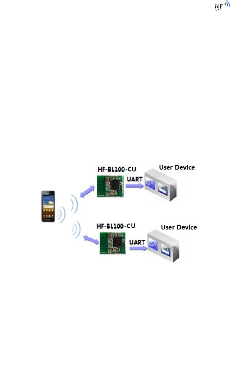
3.1. Transparent Transmit Mode
Transparent Transmit means the two way communication between device and mobile terminal
via the connecting with serial interface and device MCU. Device can set HF-BL100-CU baud
rate and connect interval via AT command through serial interface (refer to “ Serial AT
command Description” for details). Target different baud rate and BLE connect interval or
different packet sending interval, module would have different data handling capacity. The
default baud rate of HF-BL100-CU is 115200bps, it is recommended to set baud rate at
115200bps when transmitting big data or in highly real-time application. Baud rate support
save after power off.
Figure 6. Basic HF-BL100-CU wireless network structure
Module BLE connect interval is 20ms, and able to send utmost 200 byte data one time via
serial interface. Theoretically module able to send data up to 4KB/S. Below is the detail
description about transparent transmit.
Module can receive utmost 200 byte data from serial interface one time. Module will
automatically send sub-packet according to data size, each packet limit is 20 bytes. The data
packet sending from mobile device to module must separated to sub-packet(1-20 byte each).
After receive the sub-packets, module will send to MCU in proper order.
Serial hardware protocol::115200 bps , 8, non-parity,1 stop bit 。

HF-BL100-CU Low Energy Bluetooh(BLE 4.0)Module User Manual
Shanghai High Flying Electronics Technology Co., Ltd www.hi-flying.com - 19
-
After receive data from MCU serial, module will judge if it is AT command, if it is, module
will execute the command, if not, module will transmit the data to APP under BLE connection and
notify mode enabled status.
After module receive APP data, output the data to MCU via serial interface.
If module system status changed, module will send status notification character to MCU,
such as disconnect, connect, broadcast.
Bluetooth protocol require that the minimum connect interval is 7.5ms. Default connect
interval is 20ms (comply with IOS regulation), if need to save power and apply low speed
transmit mode, user can adjust connect interval through AT command ( the maximum connect
interval is 2000ms, comply with IOS regulation)
The calculation of transmit speed : the data packet of each connect interval from APP to
module is 1 packet, max 4 packet can be transmit from module to APP in each interval (the
packet qty is related to module CPU capacity) . There is max 20 bytes in each packet, if connect
interval is T (unit :ms), then max transmit speed V (unit is byte/s) is :
Vmodule = 20*4*1000/T (V only related T )
Vapp=20*1000/T (V only related T )
Vapp: if module connect interval is 20ms, then each interval can transmit max 20 bytes, so
theoretically the max speed is 20x50 =1k byte/s. Test shows the transmit from APP to
module is stable and reliable.
Vmodule: if module connect interval is 20ms, then each interval can transmit max 80 bytes,
so theoretically the max speed is 80x 50=4k byte/s. Test shows that if transmit speed under
2kbyte/s, there is few chances of leaking packet. For safety consideration, it is recommended
to do verification and re-transmit at up level whatever it is low speed or high speed application.
In Android application, it is recommended to lower connect interval to increase speed.
Below is the example of 20ms connect interval communication mode, user can self-configure.
The lower the Speed, the lower the packet lost ratio.
HF-BL100-CU Low Energy Bluetooh(BLE 4.0)Module User Manual
Shanghai High Flying Electronics Technology Co., Ltd www.hi-flying.com - 20
-
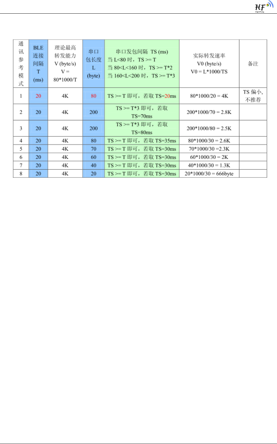
Table 8 Module connect interval 20ms communication mode example
Remark: user can set particular communication mode according to actual application, packet
length can be set between 80byte < L < 200byte ,the relationship as below as per BLE
protocol:
If L<80 ,TS >= T ;
If 80<L<160 ,TS >= T*2 ;
If 160<L<200 ,TS >= T*3 ;
All transmit mode is safe as long as meet above conditions, TS=T is recommended,
TS=T*2,TS=T*3 is ok but the packet lost ratio is high, must add verification and re-transmit
mechanism. In another words, if apply 80byte < L < 200byte ,serial data can transmit to module
in one time, but need to reserve time for sending data from module to Bluetooth, or there will
occur rear-end. E.g. Set connect interval T=20ms, if data length is L=200, TS must over T*3 =
60ms , TS=70ms is a reasonable choice.
Serial data length can be any value under 200 byte. In order to achieve the best efficiency
and avoid full load operation , it is recommended to use 20,40,60 byte serial data packet, set
packet interval over 20ms.
Remark:in IOS, the function used to call Characteristic is:
BCharacteristicWriteWithRespons
e parameter, “write with response” mode would lower transmit efficiency to ensure the
accuracy of each packet, use “ CBCharacteristicWriteWithoutResponse” ; “write without
response” mode would promote transmit efficiency , but the accuracy of packet need to be
verified by APP up level.

HF-BL100-CU Low Energy Bluetooh(BLE 4.0)Module User Manual
Shanghai High Flying Electronics Technology Co., Ltd www.hi-flying.com - 21
-
3.2. Transparent Transmit Mode Pin Description
All pins of Transparent Transmit :UART_TX、UART_RX、WAKEUP、BCTS、XRES、
MANUFACTURE
Min. pins of Transparent Transmit:UART_TX、UART_RX、WAKEUP
Details refer to 《Appendix A》
WEAKEUP: inside high impedance, pin must be connected, pull up to stop UART receive
function. UART unable to receive data (UART able to send data), pull down to enable UART to
receive data.
MANUFACTURE: pull down inside ,can be no connection, pull up outside and power on or
reset, keep high level MANUFACTURE at least 5 second, module restore factory setting
XRES: pull up inside, can be no connection
BCTS: in normal time, output low level; BCTS output high level before sending data from
module, after sending , BCTS output low level.
3.3. Factory Default Parameter
3.3.1. Device Name
Device NAME:”HF-BL100-CU”
3.3.2. Broadcast Parameter
Broadcast Min. interval:“0800”, means 500ms
Broadcast Max. interval::“0800”, means 500ms
Broadcast type:“0”, means public
Broadcast channel :“7”,means apply channel index 37 38 39
3.3.3. Transmit Power
Broadcast transmit power :”8”, means 0dbm
Connect transmit power:”8” means 0dbm

HF-BL100-CU Low Energy Bluetooh(BLE 4.0)Module User Manual
Shanghai High Flying Electronics Technology Co., Ltd www.hi-flying.com - 22
-
3.3.4. Connect Parameter
Min interval :”0016”, means 20ms
Max interval:”0032”, means 40ms
Slave Latency:”0”, means 0
Connect timeout:”0200”, means 2000ms
3.3.5. Baud rate
Baud rate:“115200”
3.3.6. Send Latency Parameter
Serial sending Latency :“01”, means 1ms
HF-BL100-CU Low Energy Bluetooh(BLE 4.0)Module User Manual
Shanghai High Flying Electronics Technology Co., Ltd www.hi-flying.com - 23
-
4. UART AT COMMAND DEFINITION
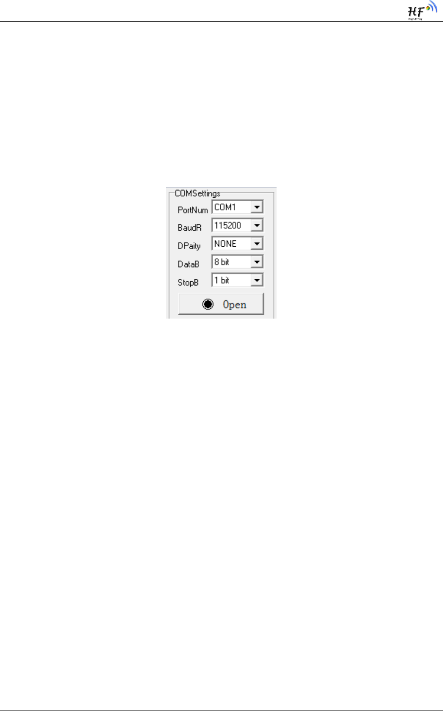
4.1. Module Operation Mode Configure
After HF-BL100-CU power on, module enter transparent transmit mode, default UART
configuration parameter as below:
Figure 7. HF-BL100-CU Default UART Parameter
User can configure the module via AT command through UART or use Evaluation Kit to test.
Evaluation kit refer to Appendix B.
<Description>: AT command debug tool recommend use “ friend serial debug assistant” and
SecureCRT tool ,which can be download from company website.
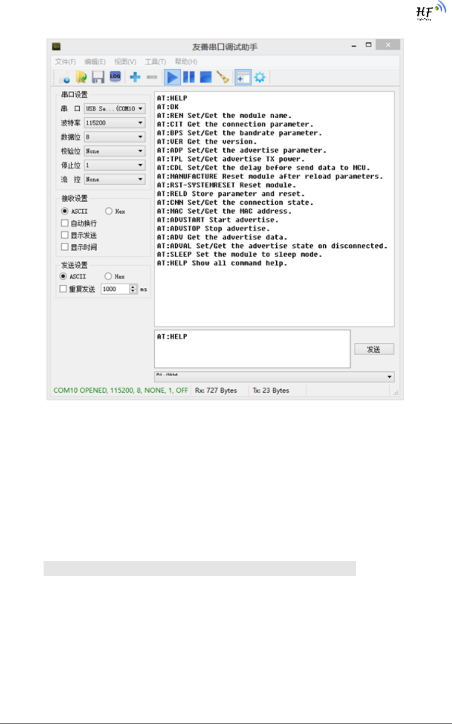
4.2. AT:Command Overview
AT: command can be inputted via serial debug tool or compile as below photo shows,
AT:HELP is a help command, list all commands and description.
Remark: the end of each command need add return or line feed character.
HF-BL100-CU Low Energy Bluetooh(BLE 4.0)Module User Manual
Shanghai High Flying Electronics Technology Co., Ltd www.hi-flying.com - 24
-
Figure 8. ”AT:HELP” list All command
4.2.1. Command Format
AT: command based on ASCII code, format as below:
Format description
< >: mean the part must include
[ ]: mean optional part
Command message
AT:<CMD>[op][para-1,para-2,para-3,para-4…]<CR><LF>
AT::command message prefix
CMD:command character string
[op] : command operate character, can be parameter setting or query
“-” : means parameter setting
“?” :means query
[para-n] : parameter setting code, if query, it is not required.
<CR>:end ,ASCII code 0x0d;
<LF>: return,ASCII code 0x0a
<descritpion>:

HF-BL100-CU Low Energy Bluetooh(BLE 4.0)Module User Manual
Shanghai High Flying Electronics Technology Co., Ltd www.hi-flying.com - 25
-
When input command,“AT:<CMD>” character is capital word, parameter parts is the same.
Feedback message
AT:<RSP>[op] [para-1,para-2,para-3,para-4…]<CR><LF><CR><LF>
AT:: feedback message prefix;
RSP: feedback character string, include:
“OK” : success
“ERP”:failed
“DENY”: operation denied
<CMD>: original command
[op] :-
[para-n] : the feedback parameter when query or error code when error
happened
<CR>:ASCII code 0x0d;
<LF>:ASCII code 0x0a;
Error code
Table 9 Error Code list
Error code
Descritpion
ERP
Invalid command
WRONG
Invalid parameter
DENY
Operation denied
4.2.2. Command List
Table 10 AT Command List
Command Type
Data transmit direction
Save or
not
Function description
Comman
d detail
"AT:HELP"
MCU->Module
No
Helo command
4.3.1
" AT:REN-" + Name
MCU->Module
Yes
Set module NAME
4.3.2
" AT:REN?"
MCU->Module
Query
Query module NAME
4.3.3
"AT+CIT-"
+IntervalMin+IntervalM
ax+Slave
Latency+connSupervisio
n Timeout
MCU->Module
Yes
Set connect parameter
4.3.4
"AT+CIT?"
MCU->Module
Query
Query connect parameter
4.3.5
"AT:BPS-"+baudrate
MCU->Module
Yes
Set baud rate
4.3.6

HF-BL100-CU Low Energy Bluetooh(BLE 4.0)Module User Manual
Shanghai High Flying Electronics Technology Co., Ltd www.hi-flying.com - 26
-
"AT:BPS?"
MCU->Module
Query
Query baud rate
4.3.7
"AT:MAC?"
(APP)MCU->Module
Query
Query MAC
4.3.9
"AT:VER?"
(APP)MCU->Module
Query
Query software version
4.3.10
"AT:TPL-" +Data0+Data1
MCU->Module
Yes
Set transmit power
4.3.11
"AT:TPL?"
MCU->Module
Query
Query transmit power
4.3.12
"AT:ADP-" +parameters
MCU->Module
Yes
Set broadcast parameter
4.3.13
"AT:ADP?"
MCU->Module
Query
Query broadcast parameter
4.3.14
"AT:ADV-"+ Data
MCU->Module
Yes
Set user-define broadcast
data
4.3.15
"AT:ADV?"
MCU->Module
Query
Query user-define
broadcast data
4.3.16
"AT:ADVAL"+data
MCU->Module
Yes
Set auto-broadcast switch
4.3.17
"AT:ADVAL?"
MCU->Module
Query
Query auto-broadcast
switch
4.3.18
"AT:ADVSTART"
MCU->Module
No
Start broadcast
4.3.19
"AT:ADVSTOP"
MCU->Module
No
Stop broadcast
4.3.20
"AT:CNN?"
MCU->Module
Query
Query current BLE
subsystem status
4.3.21
"AT:CNN-D"
MCU->Module
No
Disconnect
4.3.22
"AT:PID-"+ Data
(APP)MCU->Module
Yes
Ser device verify code
4.3.23
"AT:PID?"
(APP)MCU->Module
Query
Query device verify code
4.3.24
"AT:CDL-"+X
MCU->Module
Yes
Set UART output data
latency
4.3.25
"AT:SAVE"
(APP )MCU-
>Module
No
Save parameter
4.3.26
"AT:RST"
MCU->Module
No
Restore module
4.3.27
"AT:SLEEP-"+command
MCU->Module
No
Set module enter sleep mode
4.3.28
"AT:CNN-"+status
Module->MCU
Notifi
cation
Module BLE subsystem
status Notification
4.3.33
"AT:CPU-"+status
Module->MCU
Notifi
cation
Module CPU status
Notification
4.3.34

HF-BL100-CU Low Energy Bluetooh(BLE 4.0)Module User Manual
Shanghai High Flying Electronics Technology Co., Ltd www.hi-flying.com - 27
-
"AT:RELD"
MCU->Module
no
Restore factory setting via
AT command
4.3.35
PIN32->WAKEUP high
level outside
MCU->module
Notifi
cation
Enable module CPU
subsystem deep sleep(BLE
subsystem isolated
operation)
4.3.36
PIN29-
>MANUFACTURE keep
high level at least 5s
when power on
MCU->Module
-
Restore factory parameter
via hardware
4.3.37
* remark:UART serial interface command must end with <CR><LF>,feedback must end
with<CR><LF>
*remark:(APP)means the command is also applicable to APP command,APP command no
need <CR><LF>
4.3. AT Command
4.3.1. Help command
Function:display all command description
Effective time:effective immediately
Command:
"AT:HELP"+<CR><LF>
feedback:
"AT:OK" +<CR><LF>+data mean command success, feedback description data
Data: list all command description data
"AT:ERP\r\n" means invalid command, query failed
4.3.2. Set Module NAME
Function:set module name, max length is 11 character
Effective time: effective after re-broadcast

HF-BL100-CU Low Energy Bluetooh(BLE 4.0)Module User Manual
Shanghai High Flying Electronics Technology Co., Ltd www.hi-flying.com - 28
-
Command:
" AT:REN-" + Name+<CR><LF>
Name : display the name, max 11 character
Feedback:
"AT:OK\r\n" means success
"AT:WRONG\r\n" means invalid parameter, set failed
"AT:ERP\r\n" means invalid command, set failed
4.3.3. Query module Name
Function: query module current Name
Command
"AT:REN?"+<CR><LF>
„?‟: means query
Feedback
"AT:REN-"+devicename+<CR><LF> means success
Devicename: device name can be displayed, max 11 character, default factory name is “HF-
BL100-CU”
"AT:ERP\r\n\0" means invalid command, failed
4.3.4. Set Connect Parameter
Function:set BLE connect parameter
Effective time:effect immediately at connection status or effective after connection
Command:
"AT:CIT-"+IntervalMin+IntervalMax+Slave Latency+connSupervision Timeout+<CR><LF>
IntervalMin:4 character means,HighByte |...| LowByte;‟0‟~‟9‟ means 0~9,”0200”->
decimal 200*1.25ms
IntervalMax:4 byte means ,HighByte |...| LowByte;‟0‟~‟9‟ means 0~9,”1000”-> decimal
1000*1.25ms
Slave Latency:1 character,‟0‟~‟9‟ means 0~9,
connSupervision Timeout:4 character means ,HighCharacter|...|LowCharacter,‟0‟~‟9‟
means 0~9,”2000”-> decimal 2000*10ms

HF-BL100-CU Low Energy Bluetooh(BLE 4.0)Module User Manual
Shanghai High Flying Electronics Technology Co., Ltd www.hi-flying.com - 29
-
when connect to IOS APP ,Apple has their own regulation, for parameter must comply :
1. IntervalMax*(Slave Latency+1)《=2 seconds
2. IntervalMin>=20ms
3. IntervalMin +20ms<=IntervalMax
4. Slave Latency<=4
5. connSupervision Timeout<=6 seconds
6. IntervalMax*(Slave Latency+1)*3<connSupervisionTimeout
Feedback:
"AT:WRONG\r\n" means invalid parameter, modify failed
"AT:OK\r\n" means success, run with new connect interval
"AT:ERP\r\n" means invalid command, modify failed
4.3.5. Query Connect Parameter
Function:Query module connect parameter
Effective time:immediately
Command:
"AT:CIT?"+<CR><LF>
Feedback:
"AT+CIT-"+IntervalMin+IntervalMax+Slave Latency+connSupervision Timeout+<CR><LF>
IntervalMin:4 character means ,HighByte |...| LowByte;‟0‟~‟9‟ means 0~9,”0200”->
decimal 200*1.25ms
IntervalMax:4 character means,HighByte |...| LowByte;‟0‟~‟9‟ means 0~9,”1000”->
decimal1000*1.25ms
Slave Latency:1 character,‟0‟~‟9‟ means 0~9,
connSupervision Timeout:4 character means ,HighByte|...|LowByte,‟0‟~‟9‟ means
0~9,”2000”-> decimal 2000*10ms
when connect to IOS APP ,Apple has their own regulation, four parameter must comply:
7. IntervalMax*(Slave Latency+1)《=2 seconds
8. IntervalMin>=20ms

HF-BL100-CU Low Energy Bluetooh(BLE 4.0)Module User Manual
Shanghai High Flying Electronics Technology Co., Ltd www.hi-flying.com - 30
-
9. IntervalMin +20ms<=IntervalMax
10. Slave Latency<=4
11. connSupervision Timeout<=6 seconds
12. IntervalMax*(Slave Latency+1)*3<connSupervisionTimeout
"AT:ERP\r\n" means invalid command, query failed
4.3.6. Set Baud rate
Function:modify UART Baud rate
Effective time:effective after receiving the success feedback data
Command:
"AT:BPS-"+baud rate+<CR><LF>
Baudrate:6 character,‟0‟~‟9‟ means 0~9,”115200”-> decimal 115200
Feedback:
"AT:OK\r\n" means success
"AT:WRONG\r\n" means invalid parameter, modify failed
"AT:ERP\r\n" means invalid command, modify failed.
Remark: only apply regular baud rate 4800,9600,19200,38400,57600,115200, other
parameter would be consider invalid.
4.3.7. Query Baud rate
Function:query current baud rate
Effective time:immediately
Command:
"AT:BPS?"+<CR><LF>
Feedback:
"AT:BPS-"+baud rate+<CR><LF> means success
Baudrate:6 character ,‟0‟~‟9‟ means 0~9,”115200”-> decimal 115200,”038400”-> decimal
38400
"AT:ERP\r\n" means invalid command, query failed

HF-BL100-CU Low Energy Bluetooh(BLE 4.0)Module User Manual
Shanghai High Flying Electronics Technology Co., Ltd www.hi-flying.com - 31
-
4.3.8. Reserved
4.3.9. Get MAC Address
Function:Get Bluetooth MAC
Command:
"AT:MAC?"+<CR><LF>
APP Command do not need <CR><LF>
Feedback:
" AT:MAC-"+MAC+<CR><LF>
MAC: 12 character can represent 6 byte data, each 2 character represent the four bit in
high order and the four bit in low order of one byte.
e.g. :“123456789012”->0x12,0x34,0x56,0x78,0x90,0x12, character can only
be ‟0‟~‟9‟,‟A‟~‟F‟
APP Command do not need <CR><LF>
4.3.10. Query Software Version
function:Query device current software version
Effective time:immediately
Command:
"AT:VER?"+<CR><LF>
APP Command do not need <CR><LF>
Feedback:
"AT:VER-"+version+<CR><LF> means query success
APP Command do not need <CR><LF>
Version: character string, e.g. "100-CU-V*.*"
"AT:ERP\r\n" means invalid command, query failed
APP Command do not need "\r\n"
4.3.11. Set Transmit Power
Function: modify device transmit power, broadcast power and connect power

HF-BL100-CU Low Energy Bluetooh(BLE 4.0)Module User Manual
Shanghai High Flying Electronics Technology Co., Ltd www.hi-flying.com - 32
-
Effective time:immediately
Command
"AT:TPL-"+Data0+Data1+<CR><LF>
Data0: broadcast power, one character, ‟1‟~‟8‟ means 1~8,
Data1: connect power, one character, ‟1‟~‟8‟ means 1~8,
1-> -18dbm
2-> -12dbm
3-> -6dbm
4-> -3dbm
5-> -2dbm
6-> -1dbm
7-> +3dbm
8-> 0dbm
Feedback:
"AT:OK\r\n" means command successfully received
"AT:WRONG\r\n" means invalid parameter, modify failed, if not ‟1‟~‟8‟, then it is invalid
parameter
"AT:ERP\r\n" means invalid command, modify failed
4.3.12. Query Transmit Power
Function:query device current transmit power , broadcast power, connect power
Effective time:immediately
Command:
"AT:TPL?"+<CR><LF>
„?‟: means query command
Feedback:
"AT:TPL-"+Data0+Data1+<CR><LF>
Data0: broadcast power ,one character, ‟1‟~‟8‟ means 1~8,
Data1: connect power, one character, ‟1‟~‟8‟ means 1~8,
1-> -18dbm

HF-BL100-CU Low Energy Bluetooh(BLE 4.0)Module User Manual
Shanghai High Flying Electronics Technology Co., Ltd www.hi-flying.com - 33
-
2-> -12dbm
3-> -6dbm
4-> -3dbm
5-> -2dbm
6-> -1dbm
7-> +3dbm
8-> 0dbm
"AT:ERP\r\n" means invalid command, query failed
4.3.13. Set Broadcast Parameter
Function:set broadcast parameter, min. interval/max interval/broadcast type/broadcast
channel
Effective time:effect in next broadcast
Command:
"AT:ADP-"+parameters+<CR><LF>
Parameters: includes 13 character, min interval ->4 character, max interval ->4 character,
broadcast type->1 character, broadcast channel ->1 character
Min interval:HighByte|...|LowByte,‟0‟~‟9‟ means 0~9(“100”-> decimal 100), unit :0.625ms
Max interval:HighByte|...|LowByte,‟0‟~‟9‟ means 0~9(“1200”-> decimal 1200) ,unit:
0.625ms
Broadcast type:‟0‟~‟1‟ means 0~1,0->public,1->random,only public type available
temporarily
Broadcast channel :‟1‟~‟7‟ means 1~7,the three bit in low order correspond each channel
index. bit0->channel37,bit1->channel->38,bit2->channel39 , the setting can be combined
Feedback:
"AT:OK\r\n" means command successful received
"AT:WRONG\r\n" means invalid parameter, change failed
"AT:ERP\r\n" means invalid command, change failed

HF-BL100-CU Low Energy Bluetooh(BLE 4.0)Module User Manual
Shanghai High Flying Electronics Technology Co., Ltd www.hi-flying.com - 34
-
4.3.14. Query Broadcast Parameter
Function: query broadcast parameter, min interval/ max interval/ broadcast
type/broadcast channel
Effective time:immediately
Command:
"AT:ADP?"+<CR><LF>
Feedback:
"AT:ADP-"+parameters+<CR><LF>
Parameters: include 13 character, min interval ->4 character, max interval->4 character,
broadcast type->1 character, broadcast channel ->1 character
Min interval:HighByte|...|LowByte,‟0‟~‟9‟ means 0~9(“100”-> decimal 100) , unit:0.625ms
Max interval:HighByte|...|LowByte,‟0‟~‟9‟ means 0~9(“1200”-> decimal 1200) , unit:
0.625ms
Broadcast:‟0‟~‟1‟ means 0~1,0->public,1->random
Broadcast channel:‟1‟~‟7‟ means 1~7,the three bit in low order correspond each channel
index , bit0->channel37,bit1->channel->38,bit2->channel39, the setting can be combined.
"AT:ERP\r\n" means invalid command, query failed
4.3.15. Set User-define Broadcast Data
Function:set the user-define data in broadcast, the max data length is 11 bytes
Effective time:effective in next broadcast
Command:
"AT:ADV-"+ Data+<CR><LF>
Data: max length is 11 bytes, data format must follow Bluetooth regulation
Feedback:
"AT:OK\r\n" means command successful received
"AT:WRONG\r\n" means invalid parameter, change failed
"AT:ERP\r\n" means invalid command, change failed

HF-BL100-CU Low Energy Bluetooh(BLE 4.0)Module User Manual
Shanghai High Flying Electronics Technology Co., Ltd www.hi-flying.com - 35
-
4.3.16. Query User-define Broadcast Data
Function:query the data in user-define broadcast, max data length is 11 bytes
Effective time:immediately
Command:
"AT:ADV?"+<CR><LF>
Feedback:
"AT:ADV-"+data+<CR><LF> means command successful received and feedback data
Data: max length is 11 bytes, data format must follow Bluetooth regulation
"AT:ERP\r\n" means invalid command, change failed
4.3.17. Set Auto-broadcast Switch
Function: auto start broadcast when module power on and disconnection
Effective time:effective when disconnect
Command:
"AT:ADVAL-"+data+<CR><LF>
Data:‟0‟->disable,‟1‟-> means enable
Feedback:
"AT:OK\r
\n" means command successfully received
"AT:WRONG\r\n" means invalid parameter, command failed
"AT:ERP\r\n" means invalid command, command failed
4.3.18. Query Auto-broadcast Switch
Function: query the functions status of auto-broadcast
Effective time:immediately
Command:
"AT:ADVAL?"+<CR><LF>

HF-BL100-CU Low Energy Bluetooh(BLE 4.0)Module User Manual
Shanghai High Flying Electronics Technology Co., Ltd www.hi-flying.com - 36
-
Feedback:
"AT:ADVAL-"+status+<CR><LF> feedback current auto-broadcast switch function parameter
Status: each character indicate a status
„0‟-> disable
„1‟-> enable
"AT:WRONG\r\n" means invalid parameter, query failed
"AT:ERP\r\n" means invalid command, query failed
4.3.19. Start Broadcast
Function:device start broadcast
Effective time: do not execute if under broadcast status and connect status, execute
immediately under other status
Command:
"AT:ADVSTART"+ <CR><LF>
Feedback:
"AT:OK\r\n" means command successfully received and start broadcast
"AT:ADVSTART-"+status+<CR><LF> means command successfully received, but status
incorrect
Status: each character indicate a status
„0‟-> CYBLE_CNN_INITIALIZING
„1‟-> CYBLE_CNN_ADVERTISING
„2‟-> CYBLE_CNN_CONNECTED
„3‟-> CYBLE_CNN_DISCONNECTED
„4‟-> CYBLE_CNN_STOPPED
„5‟-> CYBLE_CNN_CONNECTING
"AT:ERP\r\n" means invalid command, command failed
4.3.20. Stop Broadcast
Function:stop broadcast

HF-BL100-CU Low Energy Bluetooh(BLE 4.0)Module User Manual
Shanghai High Flying Electronics Technology Co., Ltd www.hi-flying.com - 37
-
Effective time: execute immediately at broadcast status; do not execute if at other
status
Command:
"AT:ADVSTOP"+ <CR><LF>
Feedback:
"AT:OK\r\n" means command successfully received and stop broadcast
"AT:ADVSTOP-"+status+<CR><LF> means command successfully received, but status
incorrect
Status: each character indicate a status
„0‟-> CYBLE_CNN_INITIALIZING
„1‟-> CYBLE_CNN_ADVERTISING
„2‟-> CYBLE_CNN_CONNECTED
„3‟-> CYBLE_CNN_DISCONNECTED
„4‟-> CYBLE_CNN_STOPPED
„5‟-> CYBLE_CNN_CONNECTING
"AT:ERP\r\n" means invalid command, command failed
4.3.21. Query Current BLE Subsystem Status
Function:query current device status
Effective time:immediately
Command:
"AT:CNN?"+<CR><LF>
Feedback:
"AT:CNN-"+status+<CR><LF> means query success
Status: each character indicate a status
„0‟-> CYBLE_CNN_INITIALIZING
„1‟-> CYBLE_CNN_ADVERTISING
„2‟-> CYBLE_CNN_CONNECTED
„3‟-> CYBLE_CNN_DISCONNECTED
„4‟-> CYBLE_CNN_STOPPED
„5‟-> CYBLE_CNN_CONNECTING

HF-BL100-CU Low Energy Bluetooh(BLE 4.0)Module User Manual
Shanghai High Flying Electronics Technology Co., Ltd www.hi-flying.com - 38
-
"AT:ERP\r\n" means invalid command, query failed
4.3.22. Disconnect
Function: device disconnect
Effective time:effective immediately if device at connect status; if at other status, do not
execute command
Command:
"AT:CNN-D"+<CR><LF>
Feedback:
"AT:OK\r\n" means command received and executed
"AT:CNN-"+status+<CR><LF> means command received, but not executed because status
incorrect
Status: each character indicate a status
„0‟-> CYBLE_CNN_INITIALIZING
„1‟-> CYBLE_CNN_ADVERTISING
„2‟-> CYBLE_CNN_CONNECTED
„3‟-> CYBLE_CNN_DISCONNECTED
„4‟-> CYBLE_CNN_STOPPED
„5‟-> CYBLE_CNN_CONNECTING
"AT:ERP\r\n" means invalid command, change failed
4.3.23. Set Device Verify Code
Function:change device verify code, all “0” means no verify code
Effective time:effective in next Bluetooth connection
Command:
"AT:PID-"+ Data+<CR><LF>
APP command no need <CR><LF>
Data:4 character means 1 hexadecimal data,‟0‟~‟9‟,‟A‟~‟F‟ means 0~9,A~F(“12AD”->
hexadecimal 0x12AD)
Feedback:
"AT:OK\r\n" means command successfully received.

HF-BL100-CU Low Energy Bluetooh(BLE 4.0)Module User Manual
Shanghai High Flying Electronics Technology Co., Ltd www.hi-flying.com - 39
-
"AT:WRONG\r\n" means invalid parameter, change failed
"AT:ERP\r\n" means invalid command, change failed
APP command no need "\r\n"
4.3.24. Query Device Verify Code
Function:query device verify code parameter, all ‟0‟ means no verify code
Effective time:immediately
Command:
"AT:PID?"+<CR><LF>
„?‟: means query command
APP command no need<CR><LF>
Feedback:
"AT:PID-"+ Data+<CR><LF>
APP Command no need<CR><LF>
Data:4 Character means 1 hexadecimal data, ‟0‟~‟9‟,‟A‟~‟F‟ means 0~9,A~F(“12AD”->
hexadecimal 0x12AD)
"AT:ERP\r\n" means invalid command, query failed
APP Command no need "\r\n"
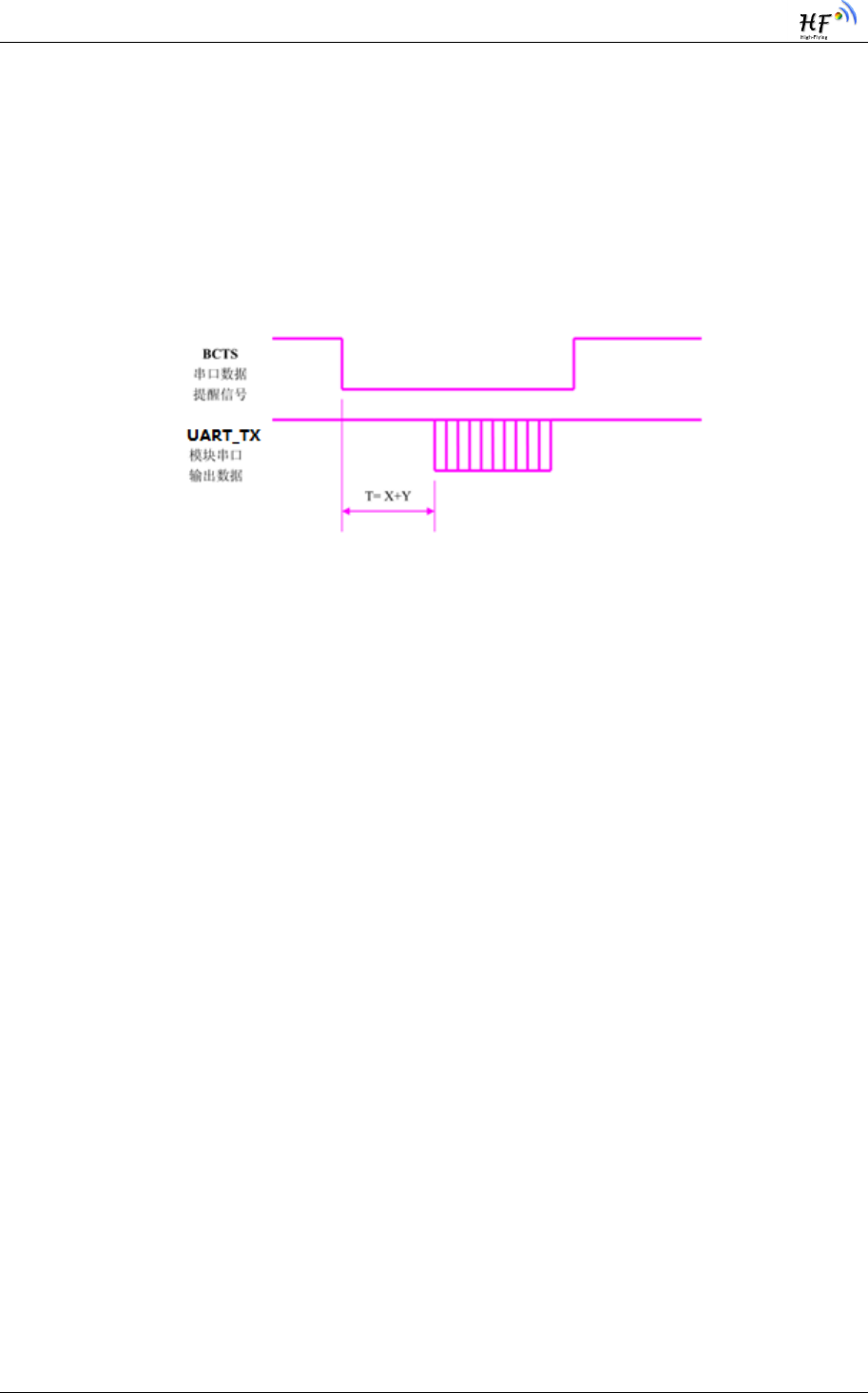
4.3.25. Set UART Output Data Latency
Function: receive data from APP, then output low level in BCTS inform outside MCU, send data
after the set latency time; during sending, BCTS keep low level until sending finished, set
BCTS high level; AT command feedback data from UART is not effected by this
Effective time:immediately
"AT:CDL-"+X+<CR><LF>
X: 2 character means 1 byte, “10”-> decimal 10,unit ms,max 10ms
Feedback:
"AT:OK\r\n" means command successfully received
"AT:WRONG\r\n" means invalid parameter, change failed
HF-BL100-CU Low Energy Bluetooh(BLE 4.0)Module User Manual
Shanghai High Flying Electronics Technology Co., Ltd www.hi-flying.com - 40
-
"AT:ERP\r\n" means invalid command, change failed
In order to enable user CPU have enough time wake up from sleep and ready to receive,
module provide a Latency (X) setting, set BCTS low level before sending data from UART, and
the data latency between BCTS to module TX is set by the parameter. Module can assure min
latency over “X” , the actual latency is T = ( X+Y ) ms ,and 500us<Y<1ms. The parameter can be
save after power off.
Figure 9. Module UART Output Data Latency Set Map
4.3.26. Save Parameter
Function:save the changed parameter( the save will stop BLE function and other interrupt,
after save, system will restore)
Effective time: immediately, save will stop BLE function and other interrupt, after save,
system will restore
Command:
"AT:SAVE"+<CR><LF>
APP command no need <CR><LF>
Feedback:
"AT:OK\r\n" means command correct
"AT:ERP\r\n" means invalid command, command failed
APP Command no need "\r\n"
4.3.27. Module Restore
Function:module restore, system software restore
Effective time: stop BLE function ,execute immediately

HF-BL100-CU Low Energy Bluetooh(BLE 4.0)Module User Manual
Shanghai High Flying Electronics Technology Co., Ltd www.hi-flying.com - 41
-
Command:
"AT:RST"+<CR><LF>
Feedback:
"AT:OK\r\n" means command successfully received
"AT:ERP\r\n" means invalid command, change failed
4.3.28. Set Module Operate Mode
function:stop BLE subsystem,force system enter Deepsleep、hibernate、stop mode,
Effective time:stop BLE function,immediately
Command:
"AT:SLEEP-"+command+<CR><LF>
Command:1-> allow CPU system enter deep sleep, process via UART
2->force CPU enter Hibernate,BLE subsystem must stop, wake up through
wake-up pin only
3->force CPU stop, BLE subsystem must stop , restore via wake-up pin and
xres only
Feedback:
"AT:OK\r\n\0" means command success
"AT:WRONG\r\n" means invalid parameter, command failed
"AT:ERP\r\n" means invalid command, command failed

HF-BL100-CU Low Energy Bluetooh(BLE 4.0)Module User Manual
Shanghai High Flying Electronics Technology Co., Ltd www.hi-flying.com - 42
-
4.3.29. Reserved
4.3.30. Reserved
4.3.31. Reserved
4.3.32. Reserved
4.3.33. Module BLE subsystem Status Notification
Function: module provide MCU the current BLE subsystem status variation
Notify time:notify when status changed
Command:
"AT:CNN-"+status+<CR><LF>
Status: each character indicate one status
„0‟-> CYBLE_CNN_INITIALIZING
„1‟-> CYBLE_CNN_ADVERTISING
„2‟-> CYBLE_CNN_CONNECTED
„3‟-> CYBLE_CNN_DISCONNECTED
„4‟-> CYBLE_CNN_STOPPED
„5‟-> CYBLE_CNN_CONNECTING
4.3.34. Module CPU Status Notification
Function:module provide current CPU status to MCU
Notify time: notify when status changed
Command:
"AT:CPU-"+status+<CR><LF>
Status: each character indicate one status
„0‟-> CPU power on
„1‟-> CPU deep sleep

HF-BL100-CU Low Energy Bluetooh(BLE 4.0)Module User Manual
Shanghai High Flying Electronics Technology Co., Ltd www.hi-flying.com - 43
-
„2‟-> CPU operate or sleep
„3‟-> CPU Hibernate
„4‟-> CPU stop
4.3.35. Restore Factory Setting via At Command
function:all changeable parameter restore to factory setting, include baud rate, device
name, transmit power, user-define broadcast data, UART data latency data, verify
code ,broadcast parameter, connect parameter
Effective time:immediately,system compulsory restore
Command:
"AT:RELD"+<CR><LF>
Feedback:
"AT:OK\r\n" means command success, system restore
"AT:ERP\r\n" means invalid command, restore failed
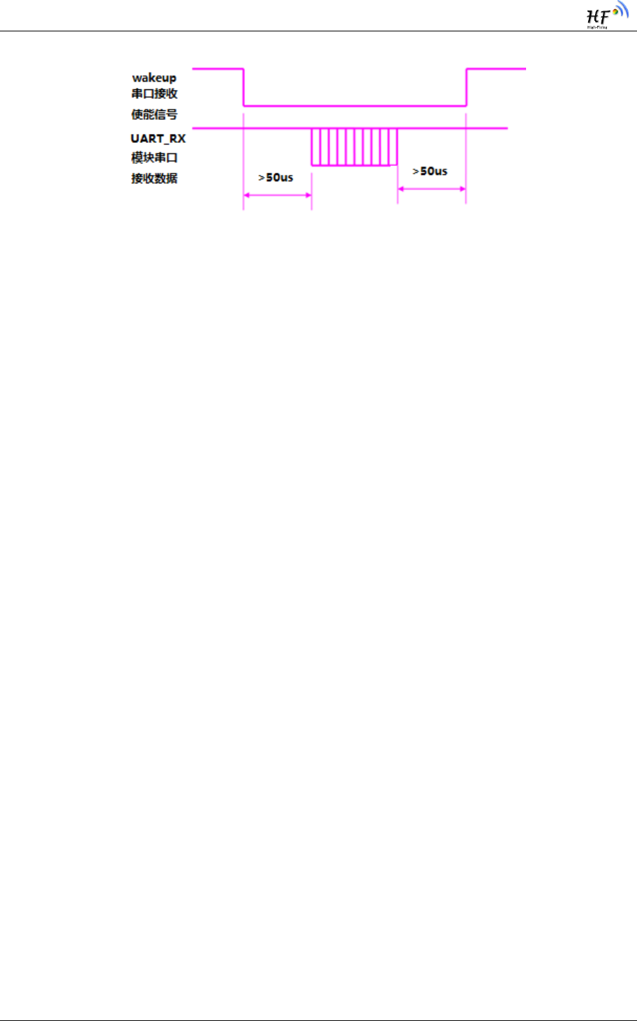
4.3.36. Enable Module Deep Sleep
Function:enable module CPU subsystem deep sleep, (BLE subsystem isolate operation), non
deep sleep mode module can receive data via UART, under deep sleep module UART function is
disabled
Effective time:immediately
Command:
PIN32->WAKEUP:high level ->CPU subsystem enter deep sleep , module UART don‟t
receive data
PIN32->WAKEUP:low level-> CPU is not allowed to enter deep sleep, module UART able to 不允
receive data
Need to pay attention to actual level and data sending sequence, sending data must wait 50
us after set high level to low level, after sending finished, and must waiting another 50 us to set
low level to high level
HF-BL100-CU Low Energy Bluetooh(BLE 4.0)Module User Manual
Shanghai High Flying Electronics Technology Co., Ltd www.hi-flying.com - 44
-
Figure 10. Module UART Receive Enable Signal Map
Feedback:
null
4.3.37. Restore Factory Setting via Hardware Method
Function:all changeable parameter restore to factory setting, include baud rate, device
name, transmit power, user-define broadcast data, UART data latency data, verify
code ,broadcast parameter, connect parameter
Effective time:immediately
Command:
PIN29->MANUFACTURE: pin pull up to power on or restore system, keep pin high level over 5
seconds after system started
Feedback:
"AT:RELOAD\r\n" means accept command to restore factory setting
4.3.38. Reserved

HF-BL100-CU Low Energy Bluetooh(BLE 4.0)Module User Manual
Shanghai High Flying Electronics Technology Co., Ltd www.hi-flying.com - 45
-
5. READ ELECTRICITY
5.1. Read Electricity Channel Configuration (temporarily unavailable)
HF-BL100-CU connect to APP, and verified with PID, then module can read electricity:
Service UUID:0x180F
Characteristic UUID:0x2A19
Prop: read
APP send data from “read” to HF-BL100-CU,and receive the feedback data from HF-
BL100-CU immediately.
5.2. Electricity Data Description
Feedback electricity data is 1 byte, unit is 20mV; the data is the actual signal value , processed
by APP

HF-BL100-CU Low Energy Bluetooh(BLE 4.0)Module User Manual
Shanghai High Flying Electronics Technology Co., Ltd www.hi-flying.com - 46
-
6. APPLICATION OTA
6.1. OTA Channel Configure
HF-BL100-CU connect to APP under “bootloader” mode:
Service UUID:00060000-F8CE-11E4-ABF4-0002A5D5C51B
Characteristic UUID:00060001-F8CE-11E4-ABF4-0002A5D5C51B
Prop: writewithresponse
6.2. OTA Data Description
Refer to the APP source code provided by Cyress

HF-BL100-CU Low Energy Bluetooh(BLE 4.0)Module User Manual
Shanghai High Flying Electronics Technology Co., Ltd www.hi-flying.com - 47
-
7. APP COMMAND
7.1. Channel and Data Description
APP command don‟t send in groups
Max data of one group command is 20 bytes
Data Channel:0x2B13 send WriteWithResponse and receive notify
7.2. Data Format
Bye length (1 byte)+ command type(1 byte)+ command content(max 18 bytes)
APP-->MODULE
Table 11 Command Data from APP to Module
Byte
length
Data[0]
1 byte
Include all byte of command type and command content
Command
type
Data[1]
1 byte
0x0E: utmost 18 bytes in one group AT command
0x0F: send verify code
Command
content
Data[2]~
data[19]
18 bytes
Details refer to command list (command type)
APP<--MODULE
Table 12 Feedback Data from Module to APP
Byte
length
Data[0]
1 byte
Including all bytes from command type and
command content
Feedback
type
Data[1]
1 byte
0x0E:max 18 bytes in one group AT command
0x0F: feedback verify result
Command
content
Data[2]~
data[19]
18 bytes
Details refer to feedback list(feedback type)

HF-BL100-CU Low Energy Bluetooh(BLE 4.0)Module User Manual
Shanghai High Flying Electronics Technology Co., Ltd www.hi-flying.com - 48
-
7.3. Command Content
7.3.1. Command Type:0x0E
Command:
Function:data write in the form of 0x2B13 writewithresponse , verify code
command refer to AT command 4.3.23 &4.3.24, query version command refer to AT
command 4.3.10
Feedback:
Channel:feedback data from 0x2B13 notify
Data content:
verify code command refer to AT command 4.3.23 &4.3.24, query version command
refer to AT command 4.3.10
7.3.2. Command Type:0x0F
Command:
Function:send verify code from APP to module, if no verification after connection,
module will not execute any other command from APP, if module self verification is null or
“0000”, then verify code is no needed.
Verify code have time limit, if no verification within 10 seconds, module will disconnect with
APP
Command Content:
Table 13 Command Type 0x0F command list
Byte
length
Data[0]
1 byte
1~19
Include all bytes from
command type and
command content
Command
type
Data[1]
1 byte
0x0F
Verify code command
Comman
d
Data[2]~data[19]
18 bytes
Data[2]~data[19]
Command content
Feedback:

HF-BL100-CU Low Energy Bluetooh(BLE 4.0)Module User Manual
Shanghai High Flying Electronics Technology Co., Ltd www.hi-flying.com - 49
-
Channel:feedback data from 0x2B13 notify
Data Content:
Table 14 Command Type 0x0F Feedback List
Byte
length
Data[0]
1 byte
2
Include all bytes from
command type and command
content
command
type
Data[1]
1 byte
0x0F
Verified and feedback
Command
content
Data[2]
1 byte
Data[2]
Verification feedback
0x00: success
0x01:failed
0x02: no verify code

HF-BL100-CU Low Energy Bluetooh(BLE 4.0)Module User Manual
Shanghai High Flying Electronics Technology Co., Ltd www.hi-flying.com - 50
-
8. BASIC COMMUNICATION
MECHANISIM
8.1. Application Service Data Channel(user-define application service
UUID:0x2B00)
Table 15 Description of User-define Service of All Channnel
UUID
Channel attribute
function
0x2B10
Notify/WriteWithResponse
APP send enable command to module via
this notify channel
Under notify enable status, module send
data to APP via notify channel
0x2B11
Read/WriteWithoutRespons
e
APP send data to module
0x2B12
WriteWithResponse
APP send OTA mode switch command
0x2B13
Notify/WriteWithResponse
APP command
8.1.1. Module->APP, UART Data Channel【feature UUID:0x2B10】
Table 16 0x2B10 feature UART Module->APP Channel Description
UUID
Executable operation
Bytes
Default
value
Remark
0x2B10
Notify/WriteWithResp
onse
20
Null
Module receive data
from UART RX ,and
notify APP via notify
channel
Remark: data input from UART and output to Bluetooth. If turn on notify enable switch,
outside MCU will send data to module RX via UART, and create a notify event in the channel, APP
can directly process in the callback function.

HF-BL100-CU Low Energy Bluetooh(BLE 4.0)Module User Manual
Shanghai High Flying Electronics Technology Co., Ltd www.hi-flying.com - 51
-
8.1.2. APP->Module,UART Data Channel【feature UUID:0x2B11】
Table 17 0x2B11 Feature UART APP->Module Channel Description
Feature value
UUID
Executable
operation
Byte
Default
value
remark
0x2B11
Read/WriteWitho
utResponse
20
null
APP write data to
module via “write”
channel, module output
data via UART
Description :input from Bluetooth and output via UART. APP write data via ”Write” channel,
the data will output via UART TX.
8.1.3. APP->Module,OTA Mode Switch【Feature UUID:0x2B12】
Table 18 0x2B12 Feature OTA Mode Switch Channel Description
Feature value
UUID
Executable
operation
Byte
Default
value
remark
0x2B12
WriteWit
houtRespo
nse
20
Null
Mode switch: switch from
application mode to OTA status,
command data is :“bootloader”
8.1.4. APP->Module,APP Command Channel【Feature UUID:0x2B13】
Table 19 0x2B13 Feature APP Command Channel Description
Feature value
UUID
Executable
operation
Byte
Default
value
remark
0x2B13
Notify/W
riteWithR
esponse
20
null
APP command, details refer to AT
command :4.3.9、4.3.10、4.3.23、
4.3.24
Note:APP do not need to add the
"AT:" prefix for AT comamnd

HF-BL100-CU Low Energy Bluetooh(BLE 4.0)Module User Manual
Shanghai High Flying Electronics Technology Co., Ltd www.hi-flying.com - 52
-
8.2. Battery Service Data Channel
Battery service UUID: 0x180F
Table 20 Description of Battery Service of All Channel
UUID
Channel attribute
function
0x2A19
read
Read electricity
8.2.1. APP->Module,Battery Data Channel 【Feature UUID:0x2A19】
Table 21 0x2A19 Feature Battery Power Channel Feature Description
Feature value
UUID
Executable
operation
byte
Default
value
remark
0x2A19
Read
1
null
Unit is 20mV
8.3. OTA Service Data Channel
OTA service UUID:00060000-F8CE-11E4-ABF4-0002A5D5C51B
Table 22 Description of OTA Service of All Channel
UUID
Channel arritbute
function
00060001-F8CE-11E4-ABF4-
0002A5D5C51B
WriteWithResponse
OTA data transmit
8.3.1. APP->Module,OTA Data Channel
Table 23 Feature OTA Data Channel Feature Description
Feature value UUID
Executable
operation
byte
Default
value
remark
00060001-F8CE-
11E4-ABF4-
0002A5D5C51B
WriteWith
Response
20
null
OTA data under ”bootloader”
mode, OTA mode receive
program data and cover
FLASH relative area
HF-BL100-CU Low Energy Bluetooh(BLE 4.0)Module User Manual
Shanghai High Flying Electronics Technology Co., Ltd www.hi-flying.com - 53
-
9. TEST
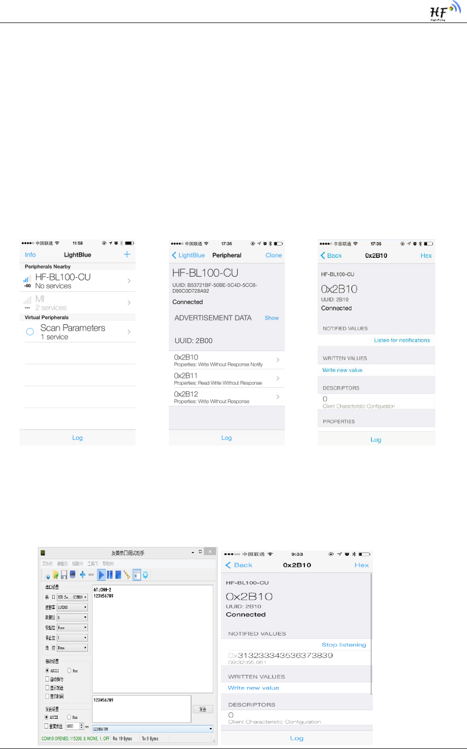
9.1. Test Transparent Transmit Function
After open “lightblue”, it will auto scan and list the devices around (if phone disabled the
Bluetooth, there will be indication of open Bluetooth), click the device name and connect. Then
switch to control main interface after connection. Click the channel with notify feature, and
press “Listen for notification” to receive data from module .
Figure 11. APP Scan & Connect Interface
Next is data packet sending test. For example, send data “123456789” via UART, phone will
receive the sending data ,as below photo shows:
HF-BL100-CU Low Energy Bluetooh(BLE 4.0)Module User Manual
Shanghai High Flying Electronics Technology Co., Ltd www.hi-flying.com - 54
-
Figure 12. APP Receive Notify Interface
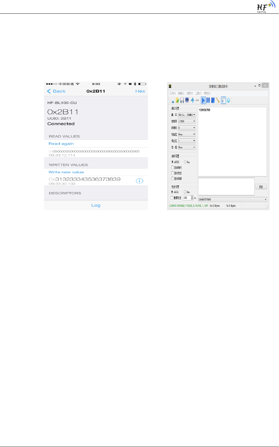
Next is data packet receive test. For examples, App sending data “123456789” , UART port
receive the sending data, as below photo shows:
Figure 13. MCU Receive write Data Interface
9.2. Test Battery Electricity Read
9.2.1. Electricity Read Command
Send read command
9.2.2. Electricity Display
Receive the feedback data and displayed in “read” display area, the data is 1 bytes ,
Hexadecimal unit is 20mv

HF-BL100-CU Low Energy Bluetooh(BLE 4.0)Module User Manual
Shanghai High Flying Electronics Technology Co., Ltd www.hi-flying.com - 55
-
9.3. OTA Function Test
9.3.1. Get Module firmware Version
Send app command from 0x2B13 to query firmware version. Type is 0x0E, refer to AT
command 4.3.10. Now Cysmart AOO do not check if module have new update
9.3.2. Switch to OTA Mode
Send “bootloader” from 0x2B12,module enter into OTA mode. Restart the module before
launch OTA, module will enter application mode; if already launched OTA , but offline or power
off without finish the OTA, module will stay at OTA mode
9.3.3. OTA
Choose the firmware file for OTA, start update until finished; if offline in halfway, module 选择
will stay in “bootloader” mode, user can restart OTA
Use cysmart to test OTA function
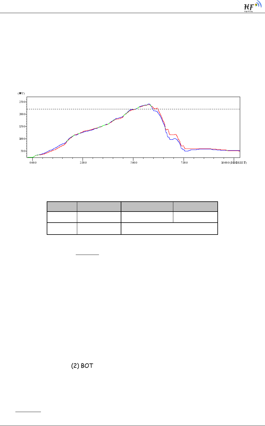
HF-BL100-CU Low Energy Bluetooh(BLE 4.0)Module User Manual
Shanghai High Flying Electronics Technology Co., Ltd www.hi-flying.com - 56
-
10. PACKAGE INFORMATION
10.1. Reflow Soldering Profile
Figure 14. Reflow Soldering Profile
Table 24 Reflow Soldering Specification
Remark: 1. Recommend to supply N2 for reflow oven
2. O2 content lower than 300ppm;
10.2. Handling Instruction
1. Shelf life in sealed bag: 12 months at <30℃, <60% humidity。
2. After bag opened, device need to be re-baked if window time over 168 hours
3. Recommended to over bake with N2 supplied
4. Recommended to reflow oven with N2 supplied
5. Bake required with 24 hours at 125+-5℃,
6. Recommended to store at ≦10% RH with vacuum packing
7. If SMT process needs twice reflow
(1) TOP side side
Case 1: BLE module mounted on PCB TOP, need to bake TOP side after BOT side processed
168 hours (window time)
Case 2: BLE module mounted on PCB BOT side ,follow normal bake rule.
Remark: window time means it is been 168 hours since last bake to next flow.
Number
Item
Temp (℃)
Time(s)
1
Reflow time
220 ℃ above
35~55 s
2
Peak temp
Max 260℃

HF-BL100-CU Low Energy Bluetooh(BLE 4.0)Module User Manual
Shanghai High Flying Electronics Technology Co., Ltd www.hi-flying.com - 57
-
10.3. Shipping Information
Tape& reel Carton
Size :TBD mm size: TBD mm(inside)
Figure 15. Package Information
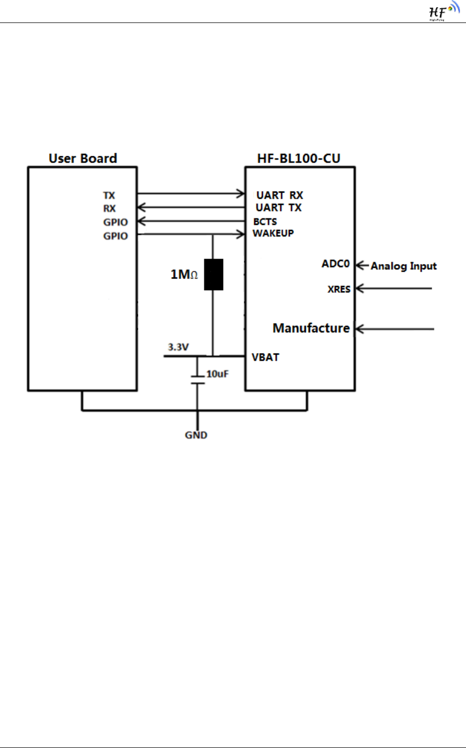
HF-BL100-CU Low Energy Bluetooh(BLE 4.0)Module User Manual
Shanghai High Flying Electronics Technology Co., Ltd www.hi-flying.com - 58
-
APPENDIX A: UART TRANSPARENT
TRANSMIT TYPICAL APPLICATION
Figure 16. UART Transparent Transmit Typical Application
XRES------module reset signal, input, low level valid
There is a pull-up resistor to VBAT, no need external pull up resistor. When module power on or
failure, MCU will reset the module, pull down at least 10 ms then pull-up.
BCTS------ Module UART output notify signal, output (wakeup external MCU, remind
MCU there is data output)
Module will pull down BCTS, and delay Xms before output data; X set by external MCU via At
command, in default there is no latency. After sending data, BCTS pull-up, if there is new
data sending BCTS will pull-up after sending all the new data. .
WAKEUP------ UART wakeup enable, Stop Mode Wakeup,(recommend to add external
Pull-up resistor)
Pin Mode: WAKEUP pin is high resistor input. Can‟t be suspended, can be controller by pull-
up or pull down or external MCU
UART Wakeup Enable: when WAKEUP is pull-up, all system enter into DEEPSLEEP ; when
WAKEUP is pull-down, system enter into SLEEP mode. When sending data from external MCU to

HF-BL100-CU Low Energy Bluetooh(BLE 4.0)Module User Manual
Shanghai High Flying Electronics Technology Co., Ltd www.hi-flying.com - 59
-
module, need to pull-down WAKEUP pin, after sending finished, pull-up WAKEUP to lower the
power.
There must be a latency from WAKEUP pull-down to MCU sending data, the time is no less 拉低
than 2ms。
Stop Mode Wakeup:WAKEUP pull-down, AT command send out Stop command, when
system enter into STOP mode, can be wakeup through pull-up WAKEUP.
UART_TX/RX------UART data send/receive signal。
Manufacture(RELD)------restore factory setting via hardware method: keep high level at
least 5 second when power on or restore
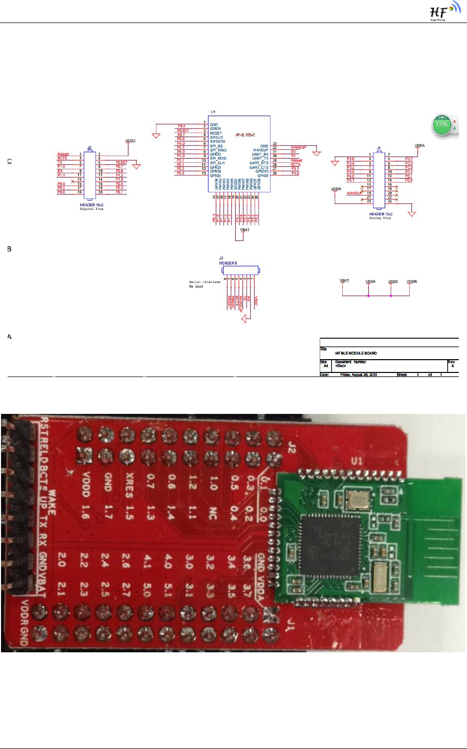
HF-BL100-CU Low Energy Bluetooh(BLE 4.0)Module User Manual
Shanghai High Flying Electronics Technology Co., Ltd www.hi-flying.com - 60
-
APPENDIX B: MODULE SCHEMATIC
Figure 17. HF-BL100-CU Module Schematic(一)
Figure 18. HF-BL100-CU EVK TOP VIEW(二)
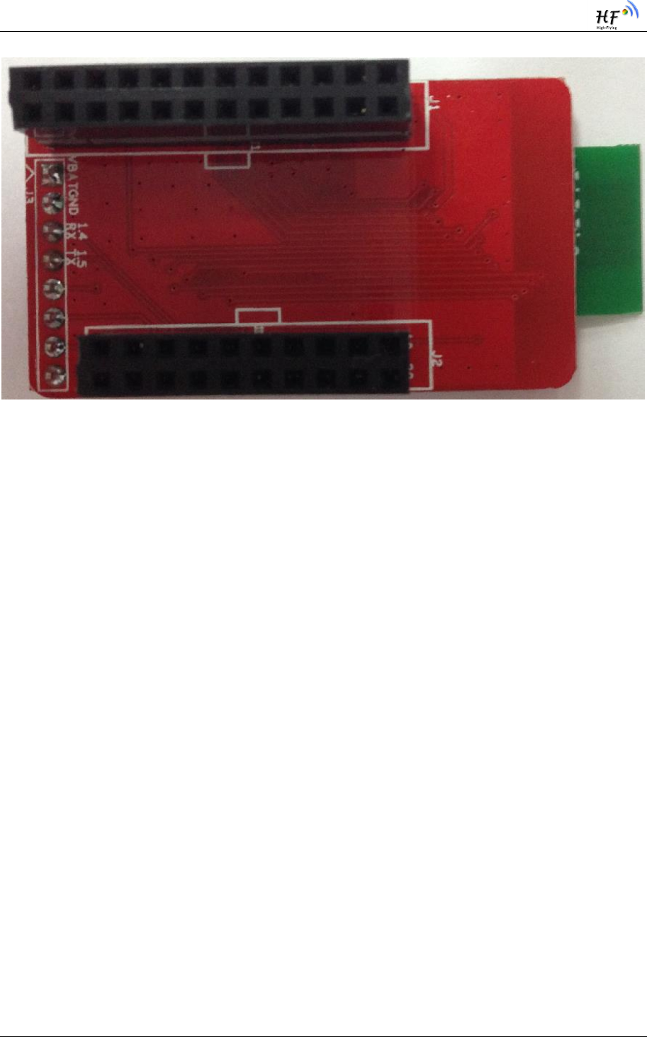
HF-BL100-CU Low Energy Bluetooh(BLE 4.0)Module User Manual
Shanghai High Flying Electronics Technology Co., Ltd www.hi-flying.com - 61
-
Figure 19. HF-BL100-CU EVK BOTTOM VIEW(三)
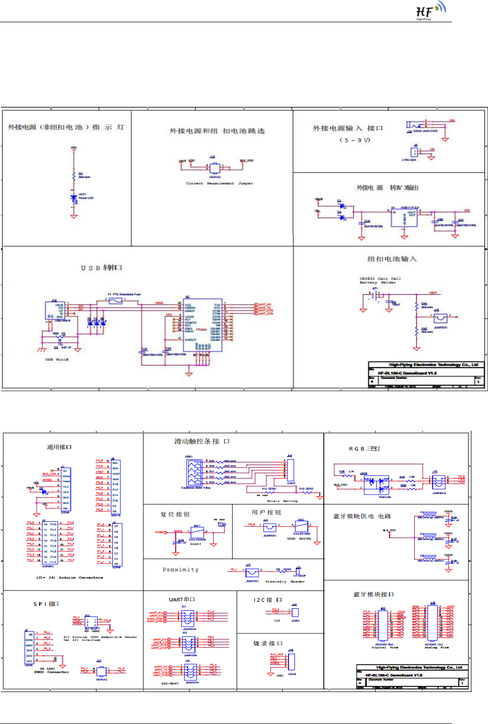
HF-BL100-CU Low Energy Bluetooh(BLE 4.0)Module User Manual
Shanghai High Flying Electronics Technology Co., Ltd www.hi-flying.com - 62
-
APPENDIX C: EVK SCHEMATIC
Figure 20. EVK Power and USB to UART Circuit(一)
Figure 21. EVK Interface Circuit(二)
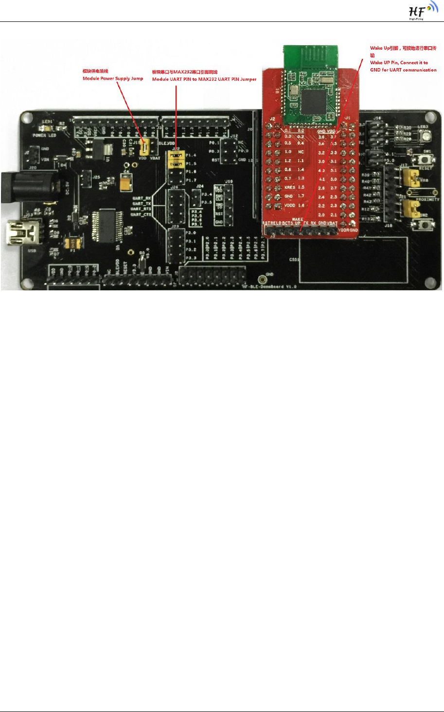
HF-BL100-CU Low Energy Bluetooh(BLE 4.0)Module User Manual
Shanghai High Flying Electronics Technology Co., Ltd www.hi-flying.com - 63
-
Figure 22. EVK Interface Circuit(三)

HF-BL100-CU Low Energy Bluetooh(BLE 4.0)Module User Manual
Shanghai High Flying Electronics Technology Co., Ltd www.hi-flying.com - 64
-
APPENDIX D: CONTACT INFORMATION
-------------------------------------------------------------------
-----------------------------------------
Address: Room 1002 ,#1Building,No.3000 Longdong Avenue, Pudong District, Shanghai, China
Post Code:201203
Web: www.hi-flying.com
Online consult: 400-189-3108
Email: sales@hi-flying.com
-------------------------------------------------------------------
----------------------------------------
For more information ,please visit http://www.hi-flying.com/

HF-BL100-CU Low Energy Bluetooh(BLE 4.0)Module User Manual
Shanghai High Flying Electronics Technology Co., Ltd www.hi-flying.com - 65
-
Federal Communication Commission Statement (FCC, U.S.)
This equipment has been tested and found to comply with the limits for a Class B digital
device, pursuant to Part 15 of the FCC Rules. These limits are designed to provide reasonable
protection against harmful interference in a residential installation. This equipment
generates, uses and can radiate radio frequency energy and, if not installed and used in
accordance with the instructions, may cause harmful interference to radio communications.
However, there is no guarantee that interference will not occur in a particular installation.
If this equipment does cause harmful interference to radio or television reception, which
can be determined by turning the equipment off and on, the user is encouraged to try to
correct the interference by one of the following measures:
- Reorient or relocate the receiving antenna.
- Increase the separation between the equipment and receiver.
- Connect the equipment into an outlet on a circuit different from that to which the
receiver is connected.
- Consult the dealer or an experienced radio/TV technician for help.
This device complies with Part 15 of the FCC Rules. Operation is subject to the following
two conditions: (1) This device may not cause harmful interference, and
(2) this device must accept any interference received, including interference that may
cause undesired operation.
FCC Caution:
Any changes or modifications not expressly approved by the party responsible for compliance
could void the user's authority to operate this equipment.
IMPORTANT NOTES
Co-location warning:
This transmitter must not be co-located or operating in conjunction with any other antenna
or transmitter.
OEM integration instructions:
This device is intended only for OEM integrators under the following conditions:
The transmitter module may not be co-located with any other transmitter or antenna. The module
shall be only used with the external antenna(s) that has been originally tested and certified
with this module.
As long as the conditions above are met, further transmitter test will not be required.
However, the OEM integrator is still responsible for testing their end-product for any
additional compliance requirements required with this module installed (for example,
digital device emissions, PC peripheral requirements, etc.).

HF-BL100-CU Low Energy Bluetooh(BLE 4.0)Module User Manual
Shanghai High Flying Electronics Technology Co., Ltd www.hi-flying.com - 66
-
Validity of using the module certification:
In the event that these conditions cannot be met (for example certain laptop configurations or
co-location with another transmitter), then the FCC authorization for this module in
combination with the host equipment is no longer considered valid and the FCC ID of the
module cannot be used on the final product. In these circumstances, the OEM integrator
will be responsible for re-evaluating the end product (including the transmitter) and obtaining
a separate FCC authorization.
End product labeling:
The final end product must be labeled in a visible area with the following:
“Contains Transmitter Module FCC ID: 2ACSVHF-BL100-CU”.
Information that must be placed in the end user manual:
The OEM integrator has to be aware not to provide information to the end user regarding how to
install or remove this RF module in the user's manual of the end product which integrates this
module. The end user manual shall include all required regulatory information/warning as
show in this manual.

HF-BL100-CU Low Energy Bluetooh(BLE 4.0)Module User Manual
Shanghai High Flying Electronics Technology Co., Ltd www.hi-flying.com - 67
-
© Copyright High-Flying, May, 2011
The information disclosed herein is proprietary to High-Flying and is not to be used by or disclosed to
unauthorized persons without the written consent of High-Flying. The recipient of this document shall respect the
security status of the information.
The master of this document is stored on an electronic database and is “write-protected” and may be altered only
by authorized persons at High-Flying. Viewing of the master document electronically on electronic database
ensures access to the current issue. Any other copies must be regarded as uncontrolled copies.