High Flying Electronics Technology HF-LPB100 Embedded WiFi Module User Manual Manual
High-Flying Electronics Technology Co.,Ltd Embedded WiFi Module Manual
UserManual.wiki
>
High Flying Electronics Technology
>
HF-LPB100 User Manual
>
Manual
Contents
1.
Manual
2.
User manual
Manual
Navigation menu
Upload a User Manual
Namespaces
Wiki Guide
HTML
PDF
Info
Views
User Manual
Discussion / Help
Navigation
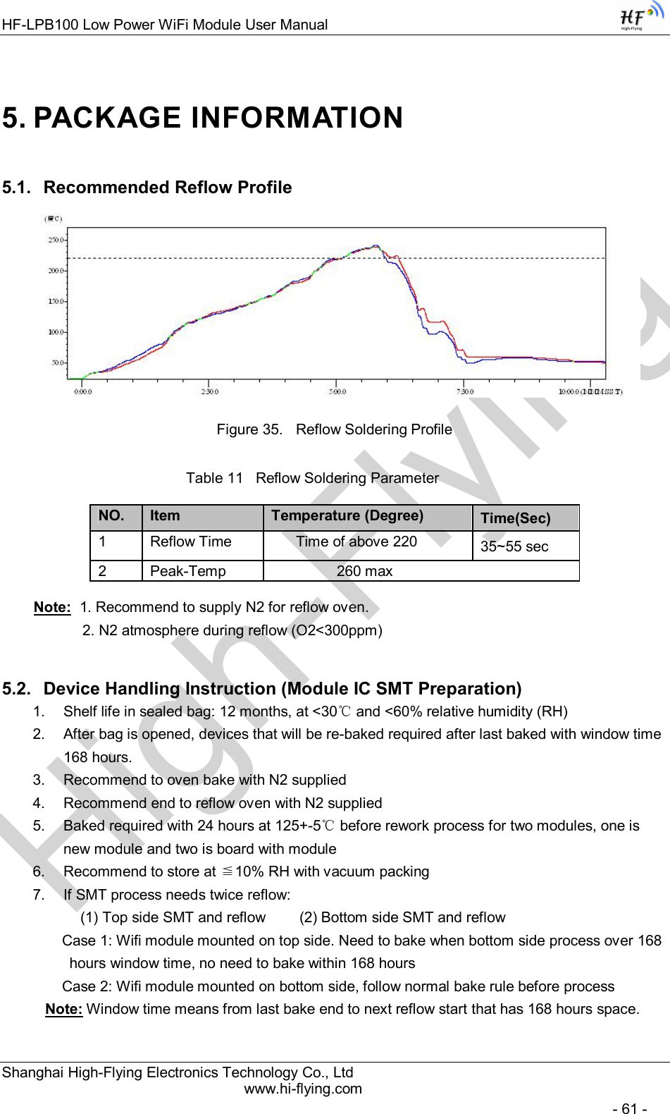
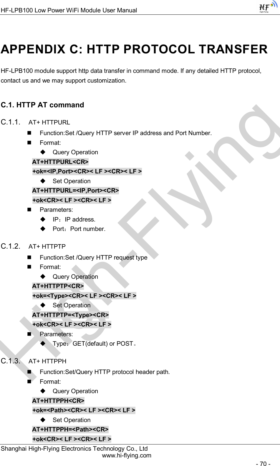
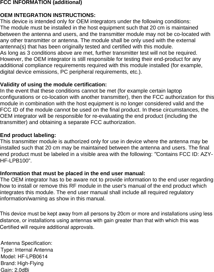
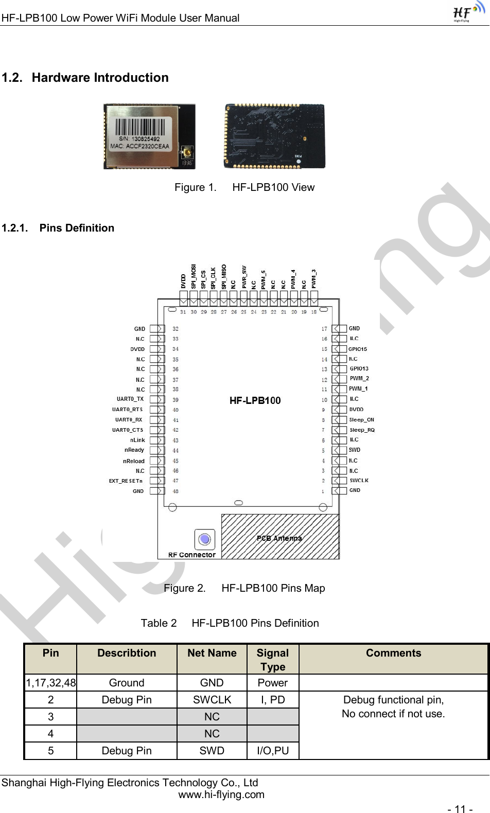
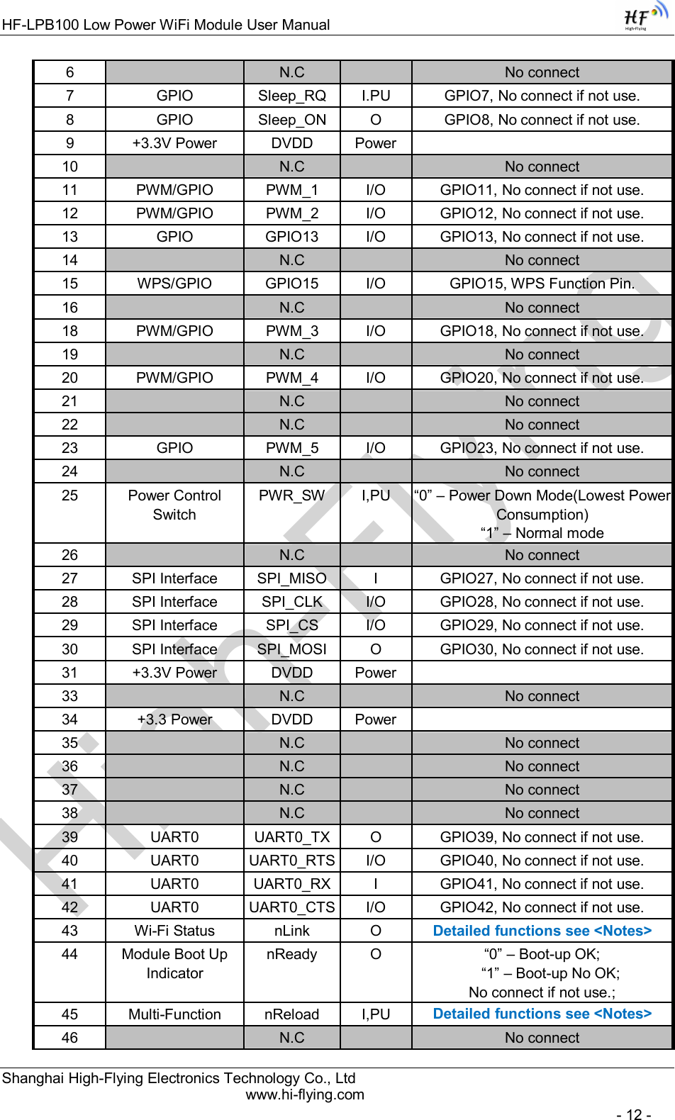
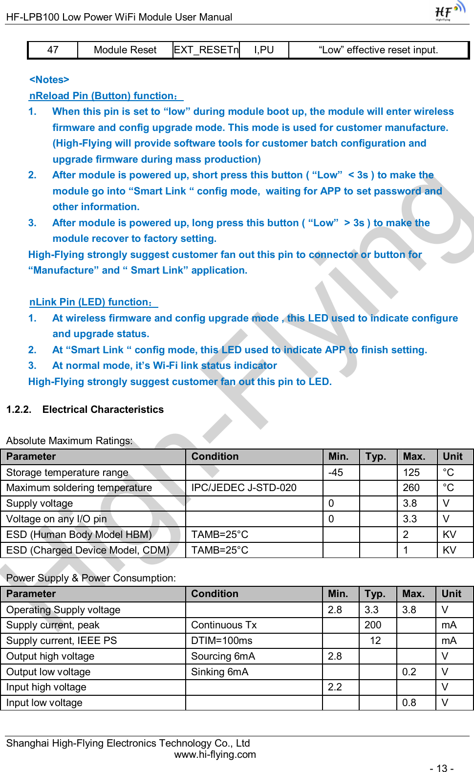
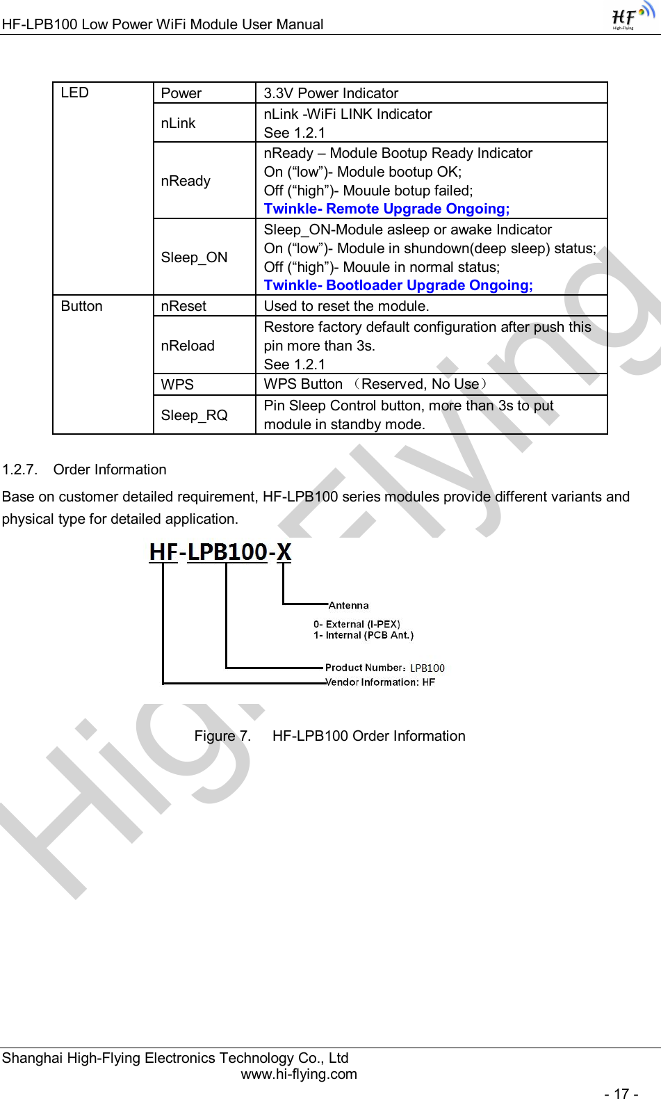
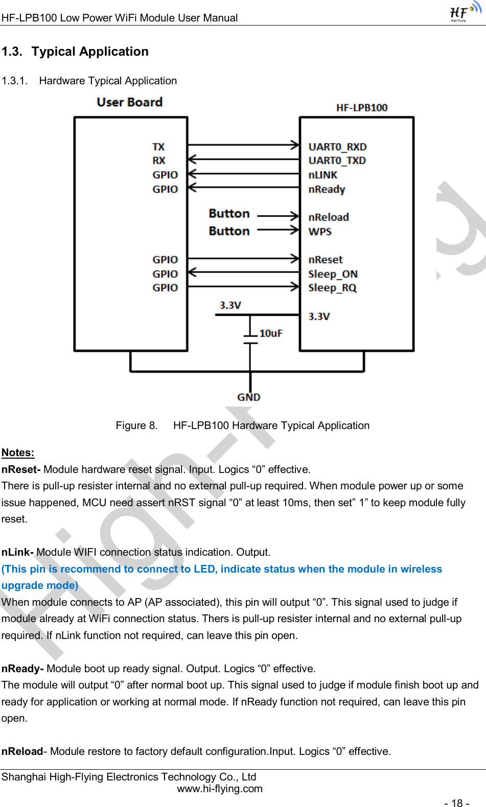
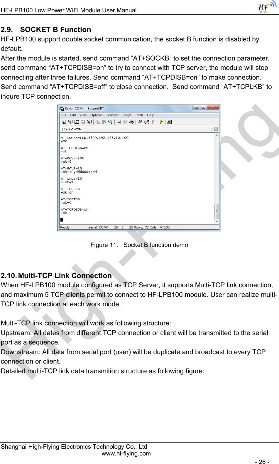
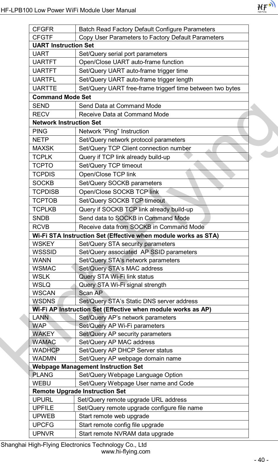
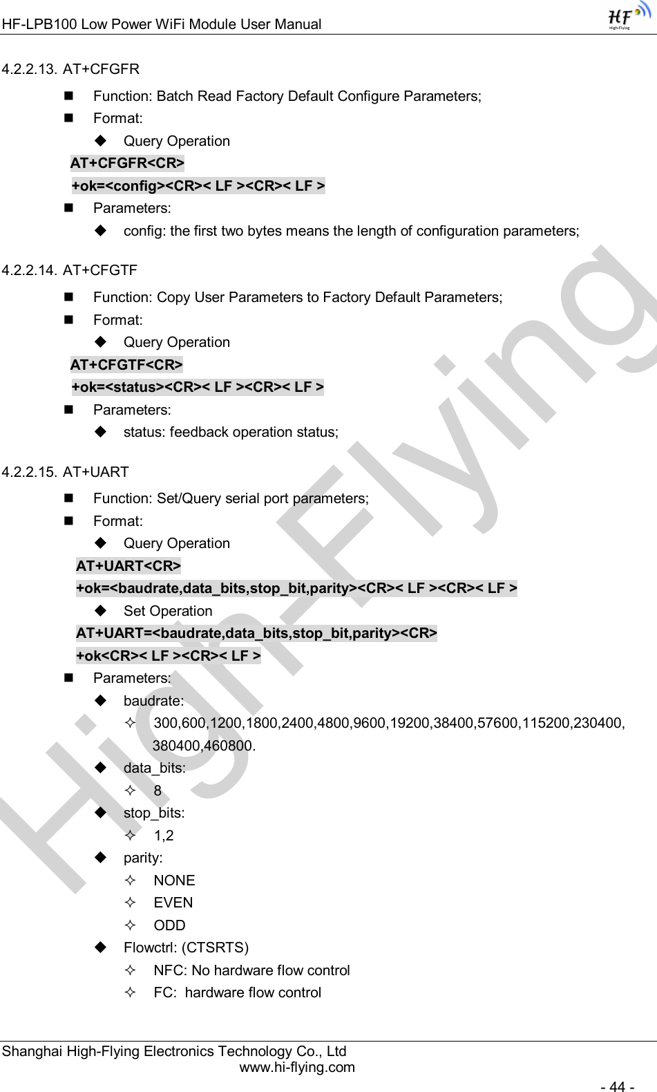
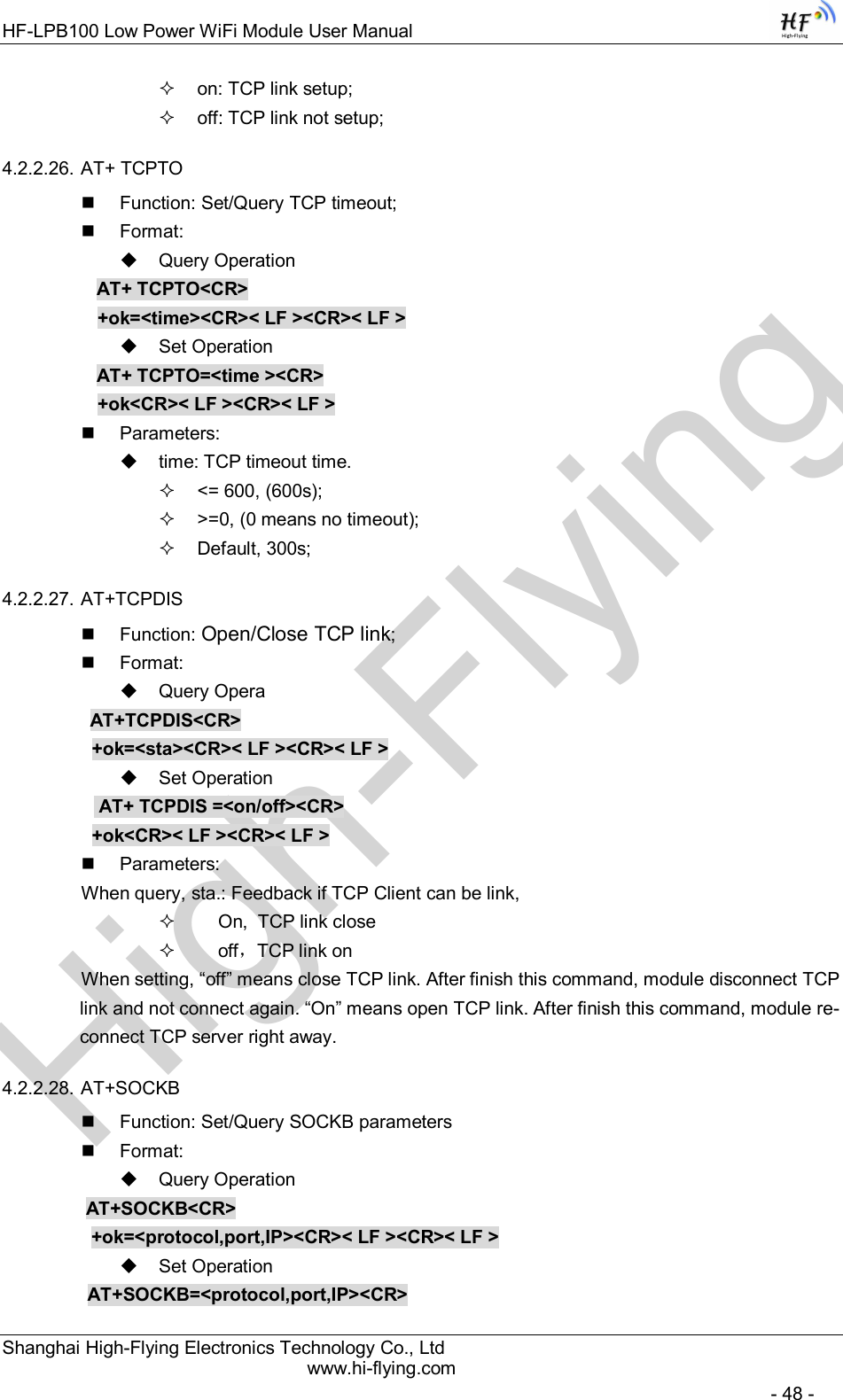
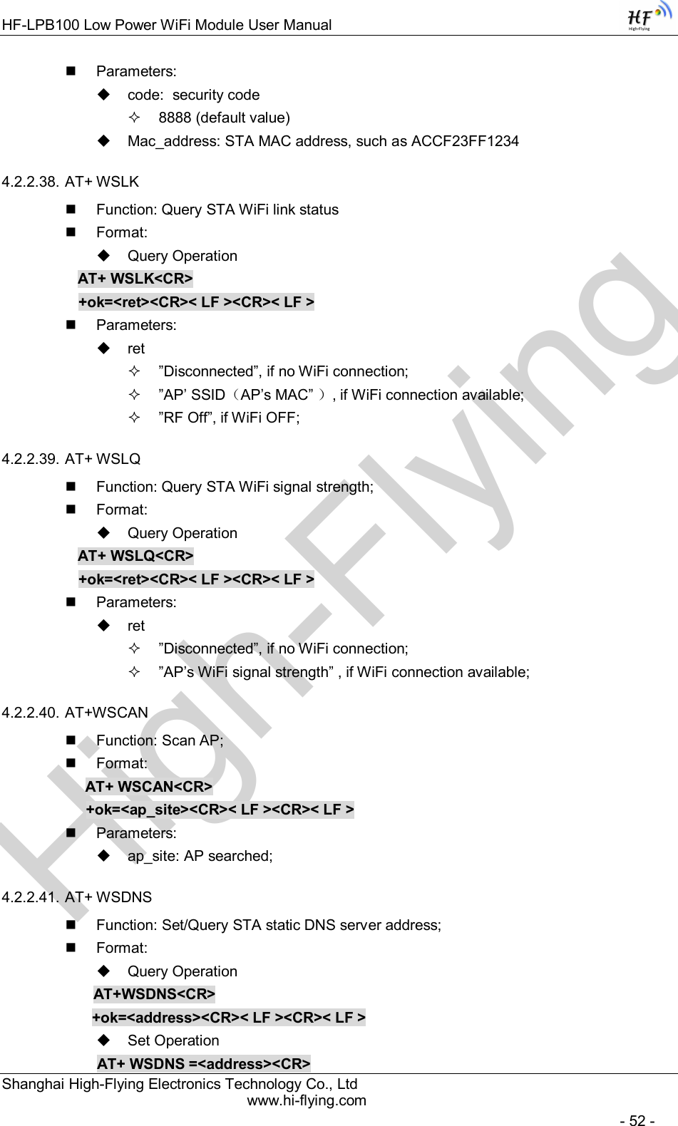
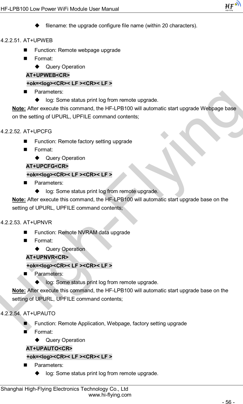
![High-FlyingHF-LPB100 Low Power WiFi Module User Manual Shanghai High-Flying Electronics Technology Co., Ltd www.hi-flying.com - 10 - 1.1.2 Device Paremeters Table 1 HF-LPB100 Module Technical Specifications Class Item Parameters Wireless Parameters Certification FCC/CE Wireless standard 802.11 b/g/n Frequency range 2.412GHz-2.484GHz Transmit Power 802.11b: +16 +/-2dBm (@11Mbps) 802.11g: +14 +/-2dBm (@54Mbps) 802.11n: +13 +/-2dBm (@HT20, MCS7) Receiver Sensitivity 802.11b: -93 dBm (@11Mbps ,CCK) 802.11g: -85 dBm (@54Mbps, OFDM) 802.11n: -82 dBm (@HT20, MCS7) Antenna Option External:I-PEX Connector Internal:On-board PCB antenna Hardware Parameters Data Interface UART SPI, PWM, GPIO Operating Voltage 2.8~3.6V Operating Current Peak [Continuous TX]: ~200mA Normal [WiFi ON/OFF, DTIM=100ms]: Average. ~12mA, Peak: 200mA Standby [WiFi Shutdown]: <200uA Power Down Switch: <10uA Operating Temp. -40℃- 85℃ Storage Temp. -45℃- 125℃ Dimensions and Size 23.1mm×32.8mm×2.7mm Software Parameters Network Type STA /AP/STA+AP Security Mechanisms WEP/WPA-PSK/WPA2-PSK Encryption WEP64/WEP128/TKIP/AES Update Firmware Local Wireless, Remote Customization Web Page Upgrade Support SDK for application develop Network Protocol IPv4, TCP/UDP/FTP/HTTP User Configuration AT+instruction set. Android/ iOS Smart Link APP tools 1.1.3 Key Application Remote equipment monitoring Asset tracking and telemetry Security Industrial sensors and controls Home automation Medical devices](https://usermanual.wiki/High-Flying-Electronics-Technology/HF-LPB100.Manual/User-Guide-2150598-Page-10.png)
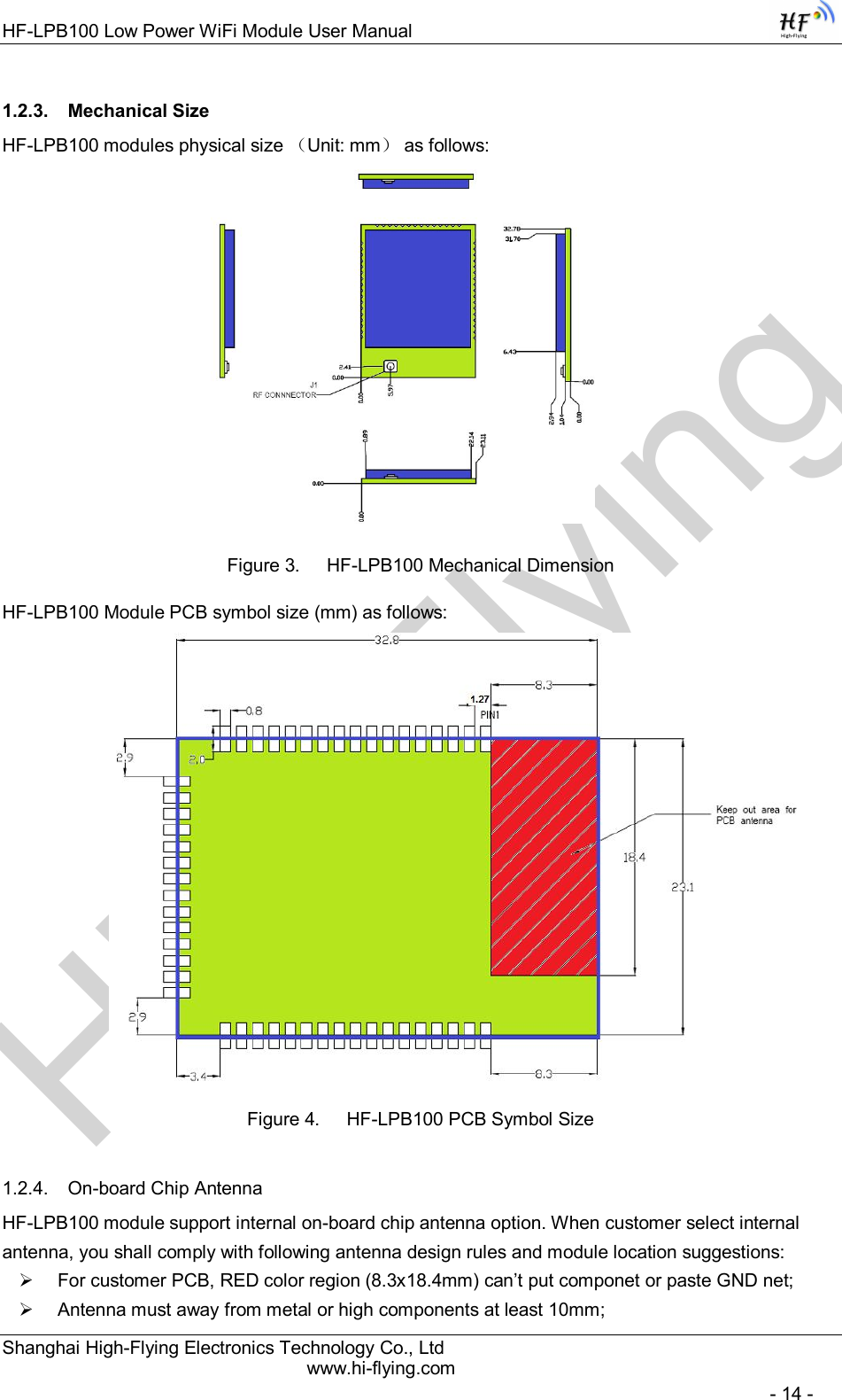
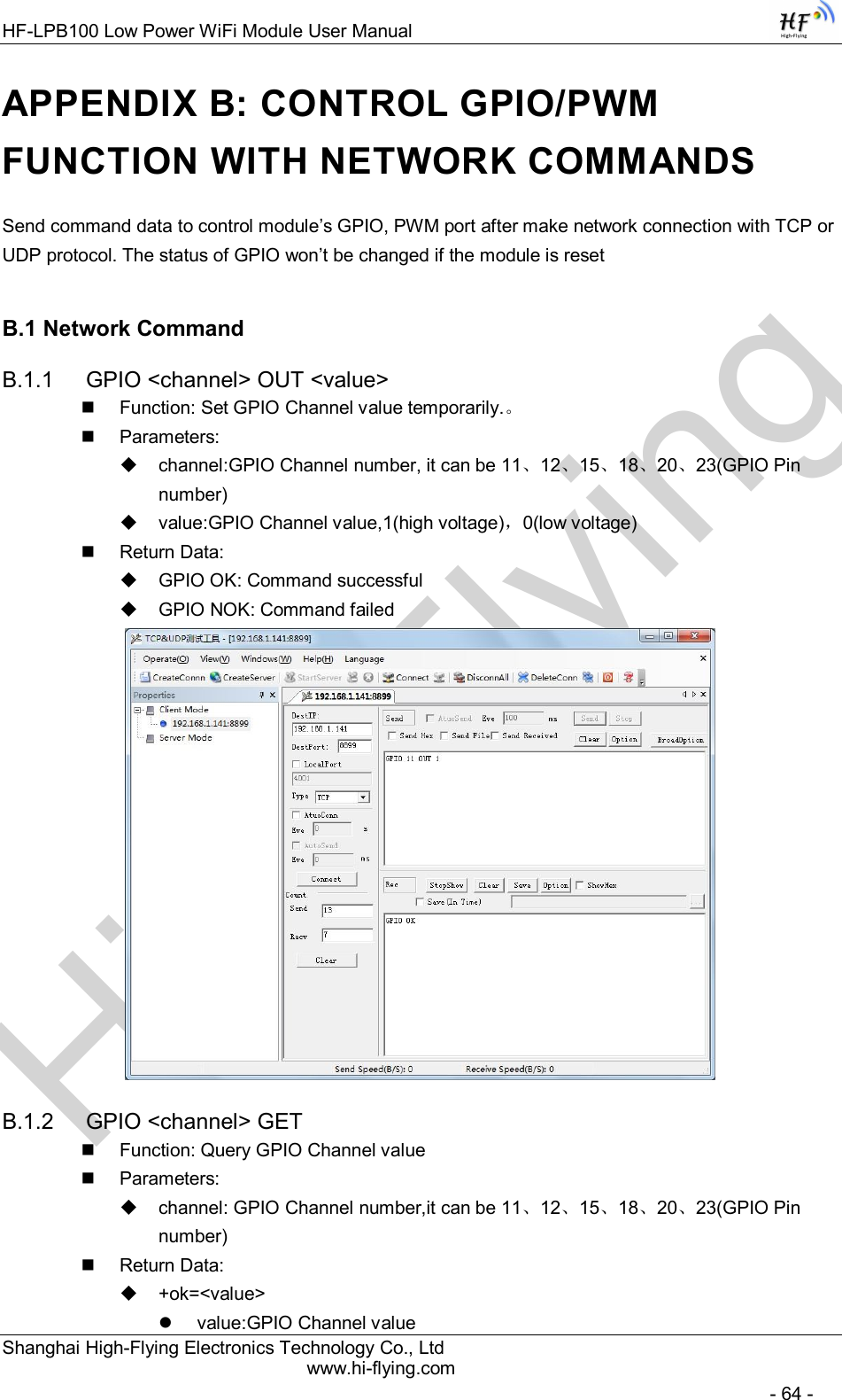
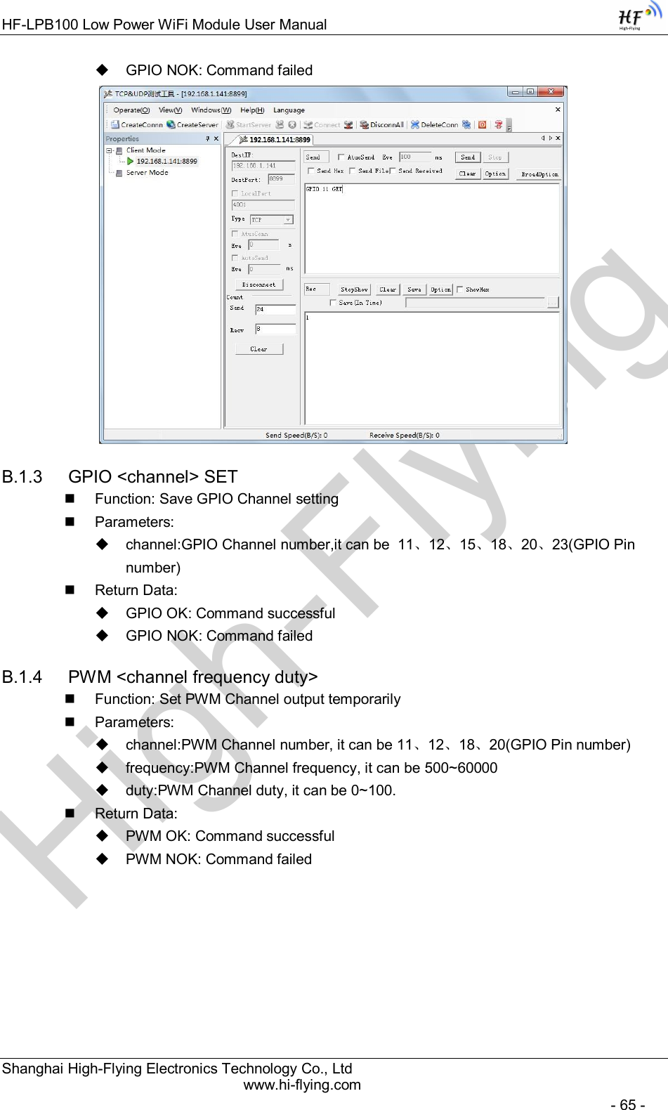
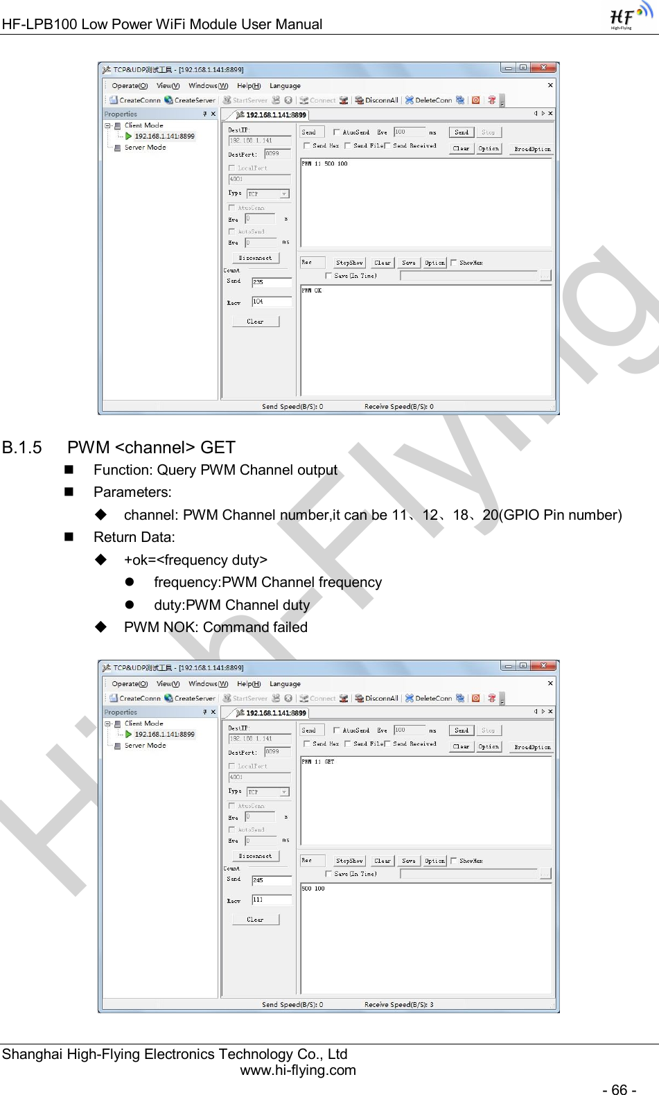
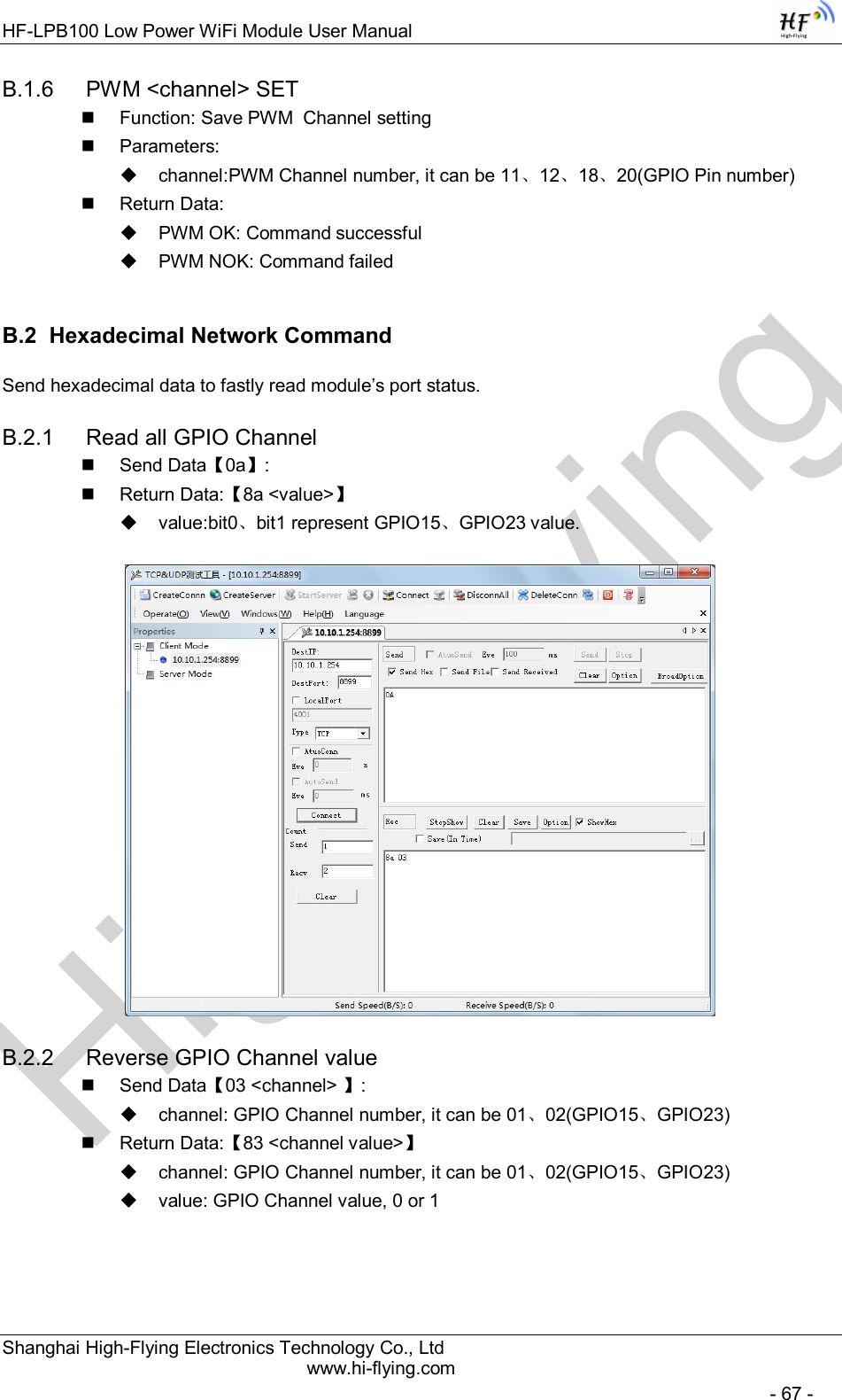
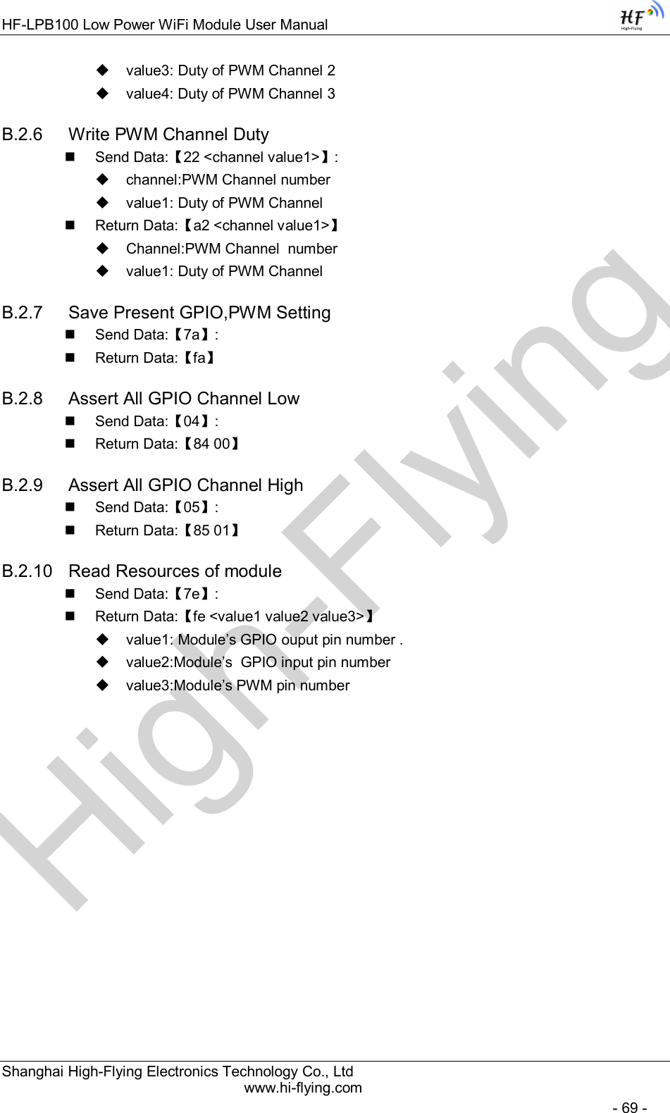
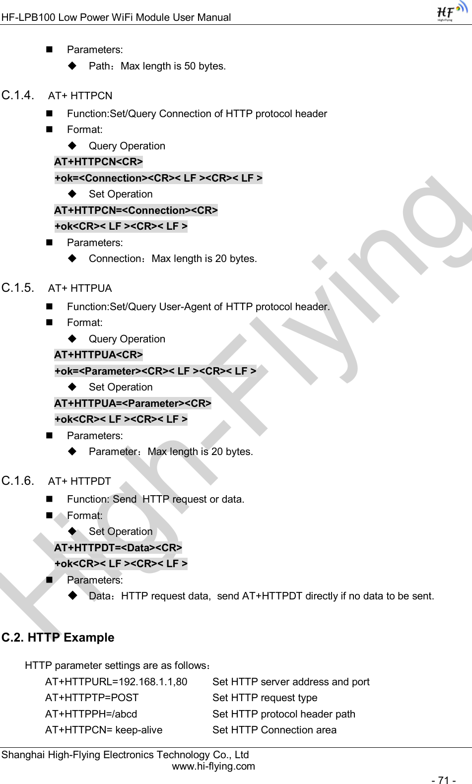
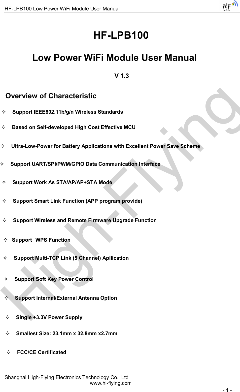
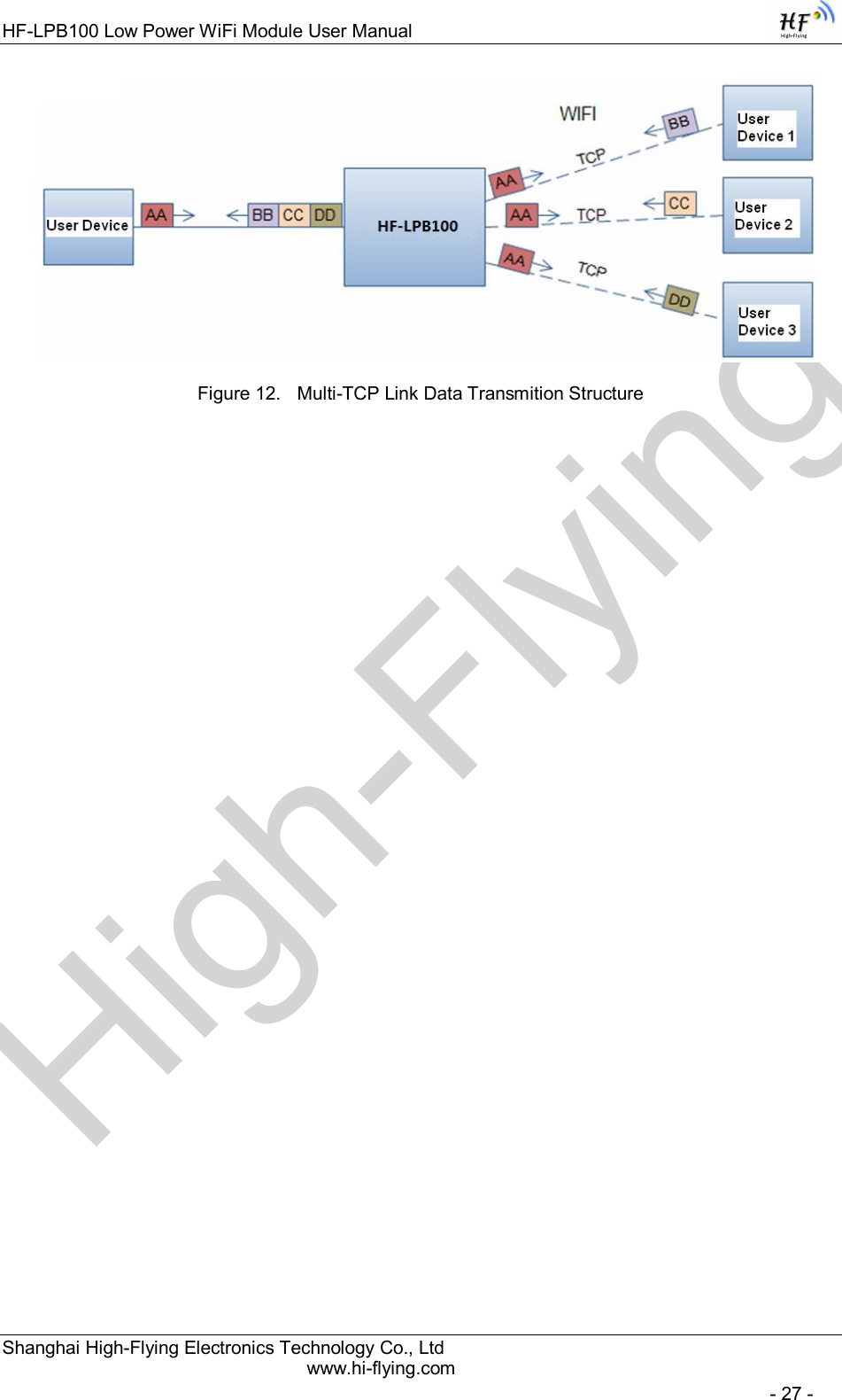
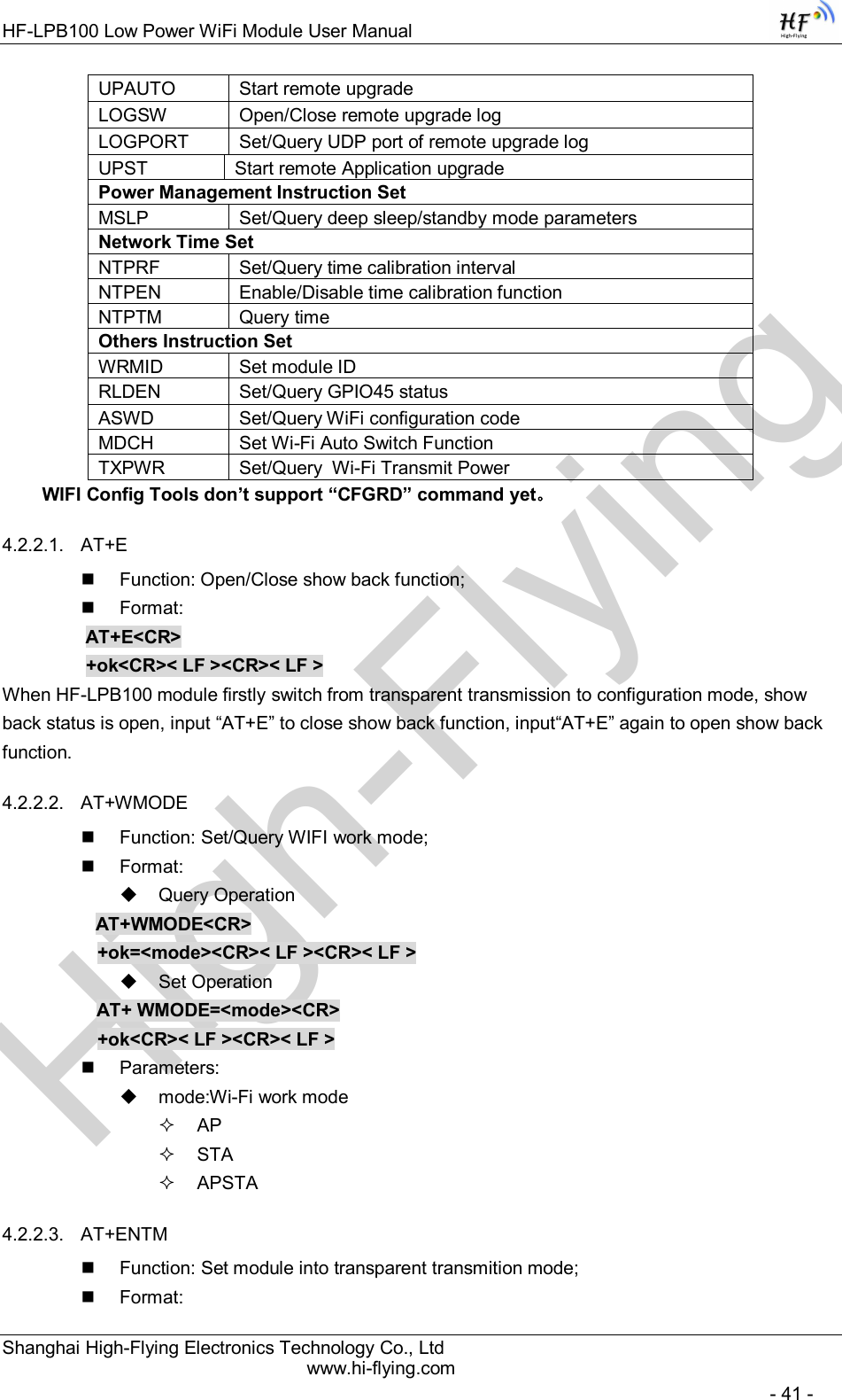
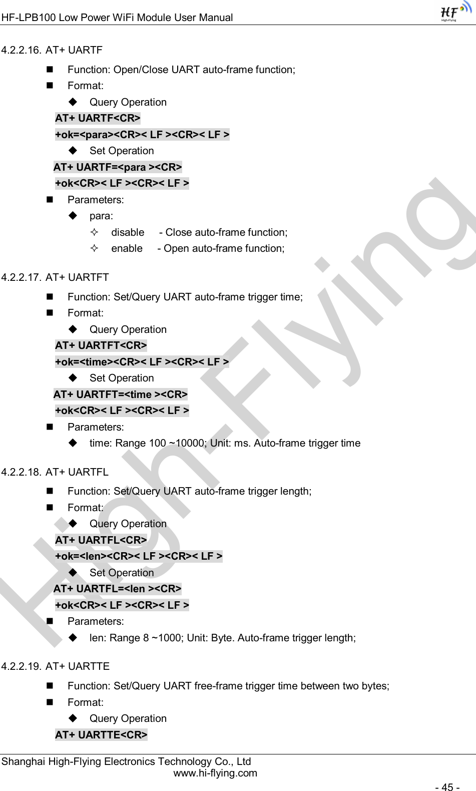
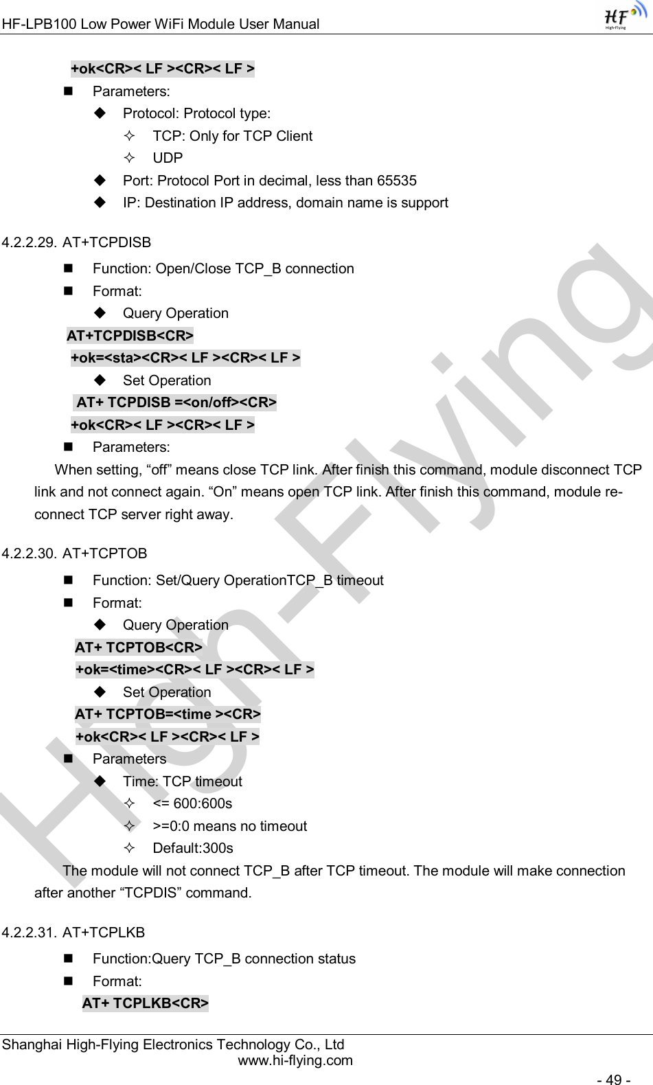
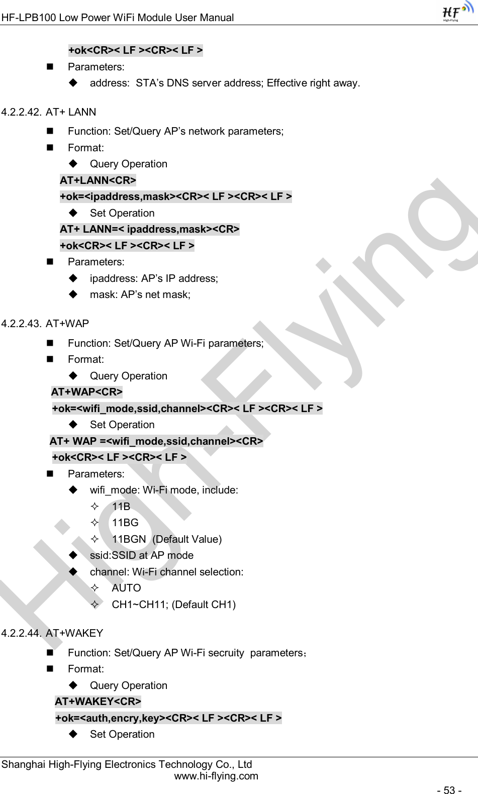
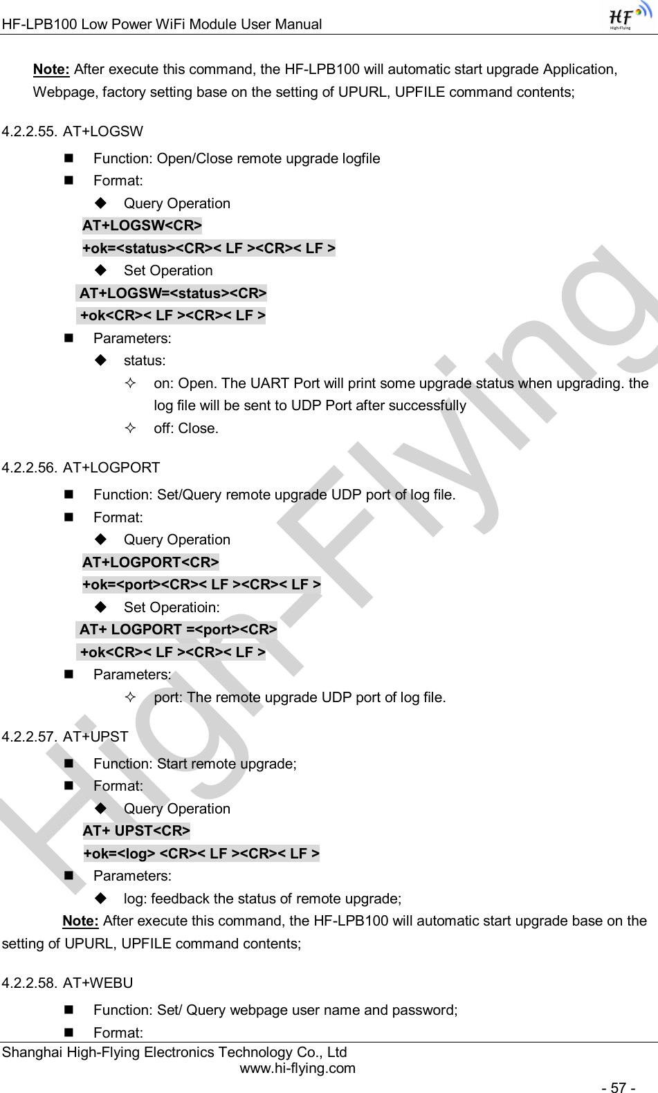
![High-FlyingHF-LPB100 Low Power WiFi Module User Manual Shanghai High-Flying Electronics Technology Co., Ltd www.hi-flying.com - 25 - General “config.txt” file format as following example: [URL]=”http://10.10.100.100:80/lpb.bin” [WEB]="http://10.10.100.100:80/web.bin" [NVR]="http://10.10.100.100:80/nvram.dat" [CFG]= "http://10.10.100.100:80/cfg.bin" [URL]= the URL address of Application. [WEB]=the URL address of Webpage [NVR]= the URL address of NVRAM data [CFG]= the URL address of Factory Parameter File Direct Download and Upgrade AT+UPURL command to set the remote directory and file name, such as: AT+UPURL=http://www.hi-flying.com/!admin/down/,lpb.bin After excuate this command, the module will directly download the “lpb.bin” file from remote directory and start upgrade Application. Notes: please contact with high-flying technical people before upgrade firmware, or maybe damage the module and can’t work again. 2.8. GPIO/PWM Function HF-LPB100 module can provide many GPIOs, which include max 6 PWM/GPIO control pins. User devices can read/write GPIO/PWM pins status. Table 7 HF-LPB100 GPIO/PWM Pin Mapping Table When module works at PWM mode, PC and other devices can setup connection (TCP/UDP) through WiFi, then read/write GPIO/PWM information through command data. GPIO n OUT 0, Set GPIOn as output and output ‘0’, Response GPIO OK or GPIO NOK; GPIO n OUT 1, Set GPIOn as output and output ‘1’, Response GPIO OK or GPIO NOK; GPIO n GET, Read GPIOn pin status, Response +ok=1 or GPIO NOK GPIO n SET, Save GPIOn set, Response GPIO OK or GPIO NOK PWM n frequency duty, Set PWMn Channel output, Response GPIO OK or GPIO NOK PWM n GET, Read PWMn Channel set, Response +ok=frequency duty or PWM NOK PWM n SET, Save PWMn Channel set, Response PWM OK or PWM NOK Notes: Please refer to Appendix B for details to use GPIO/PWM. GPIO Configured Function Describtion Default Setting Type GPIO11 PWM/GPIO Channel PWM_1 GPIO11 I/O GPIO12 PWM/GPIO Channel PWM_2 GPIO12 I/O GPIO15 GPIO Channel GPIO15 GPIO15 I/O GPIO18 PWM/GPIO Channel PWM_3 GPIO18 I/O GPIO20 PWM/GPIO Channel PWM_4 GPIO20 I/O GPIO23 GPIO Channel PWM_5 GPIO23 I/O](https://usermanual.wiki/High-Flying-Electronics-Technology/HF-LPB100.Manual/User-Guide-2150598-Page-25.png)
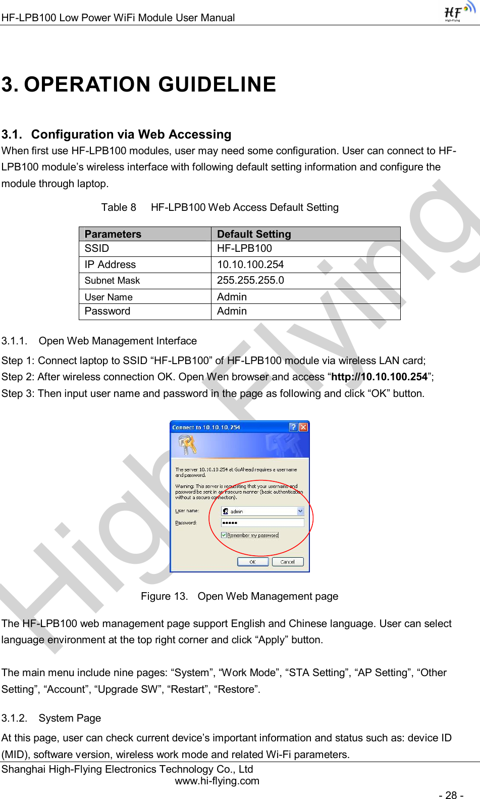
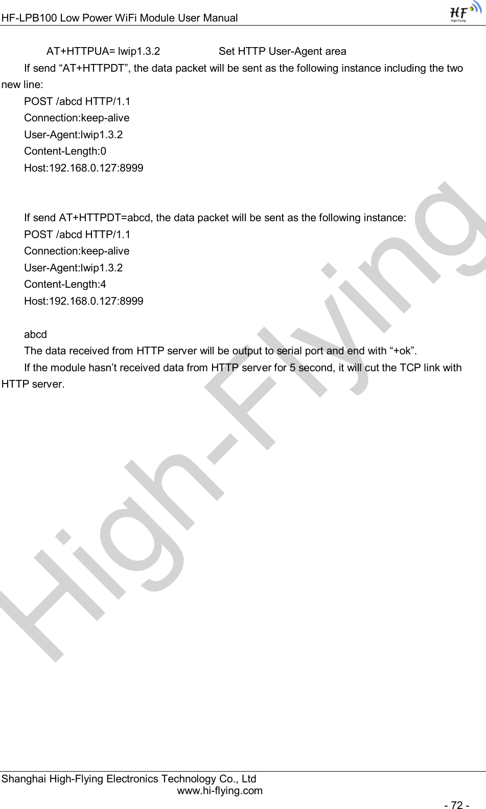
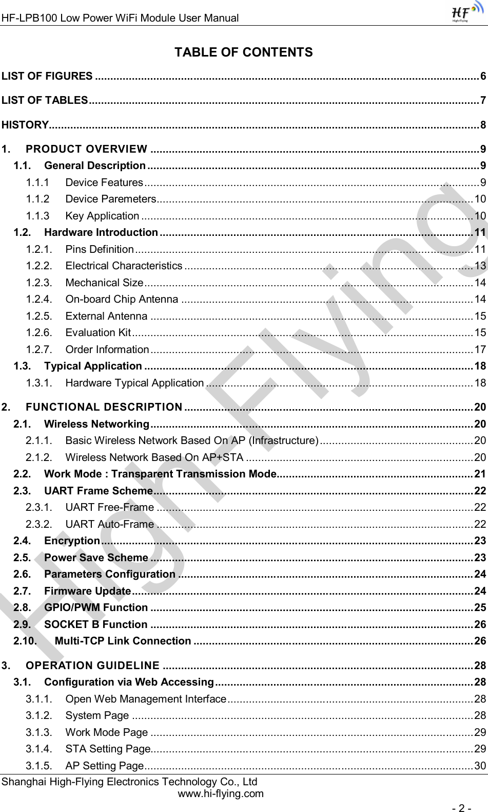
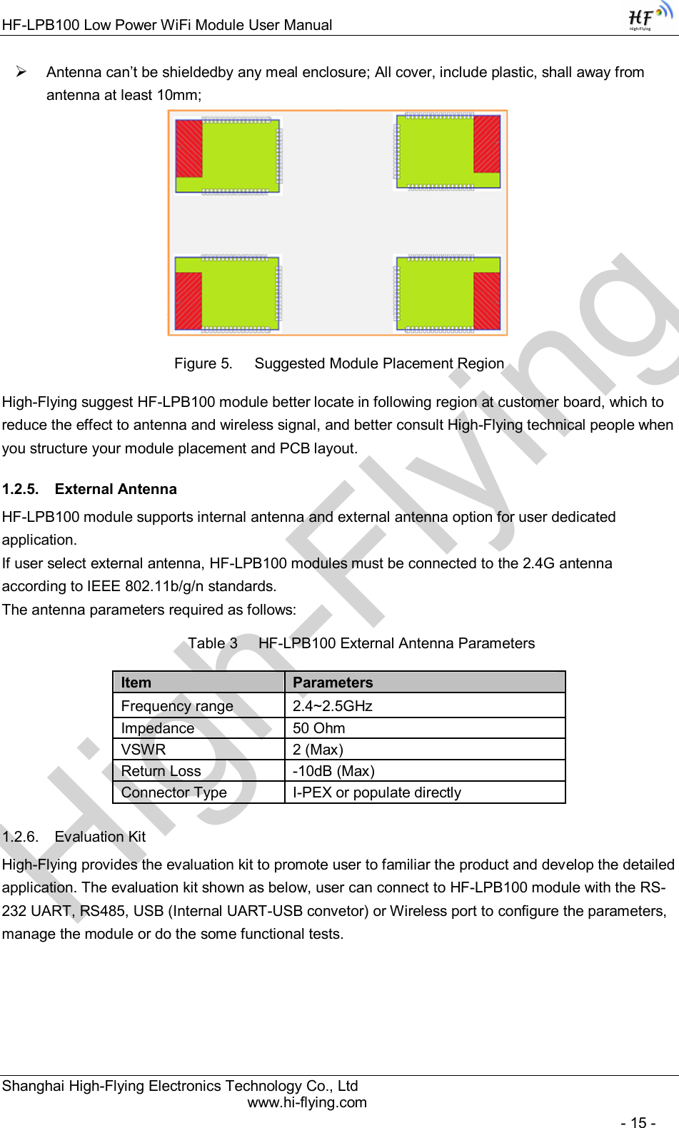
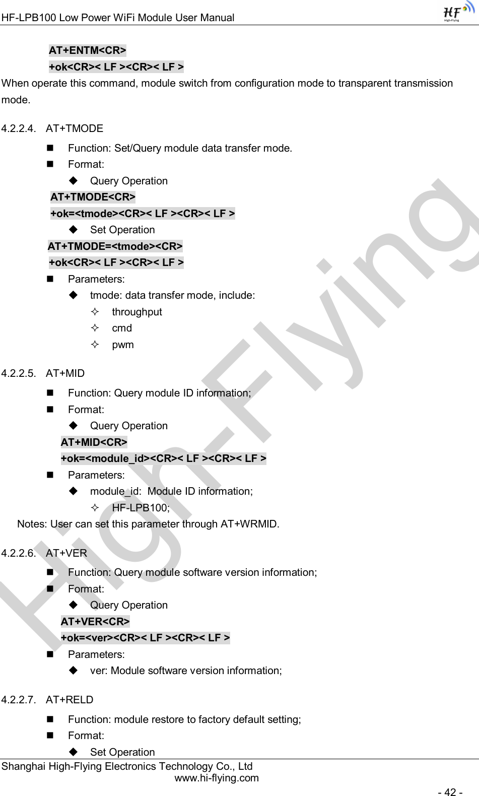
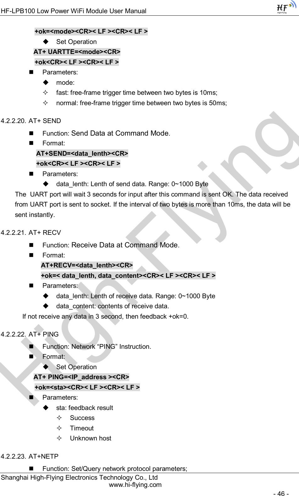
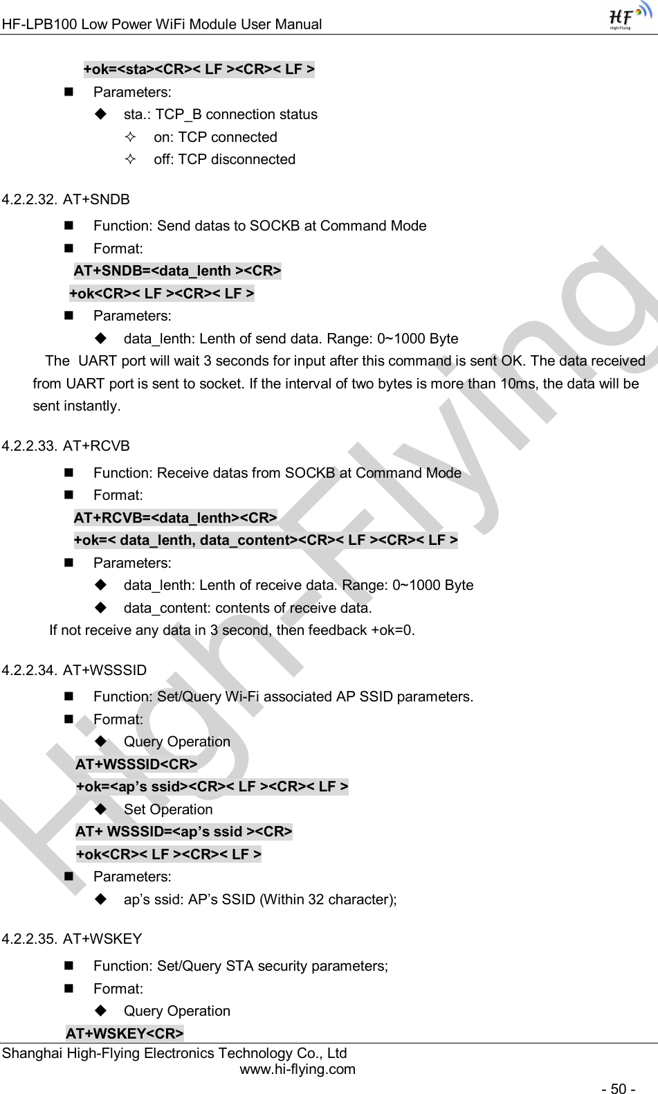
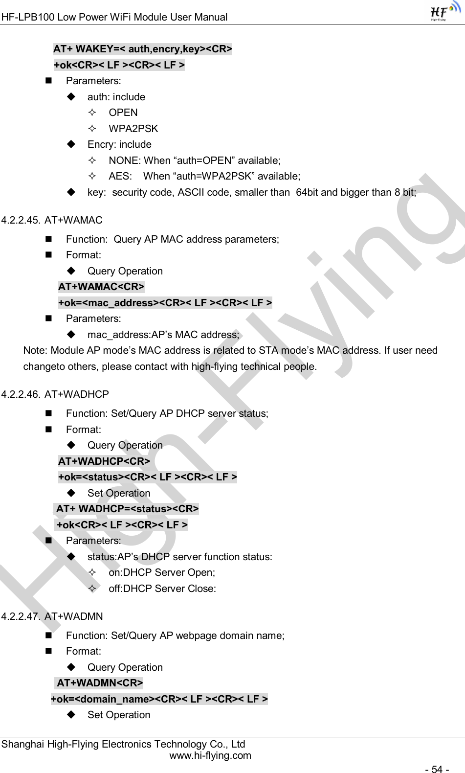
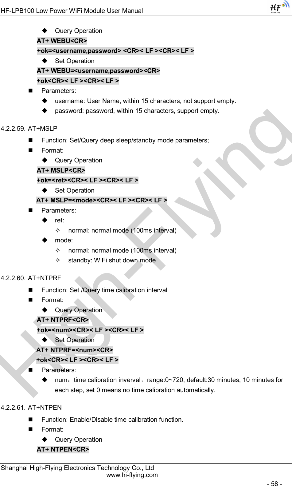
![High-FlyingHF-LPB100 Low Power WiFi Module User Manual Shanghai High-Flying Electronics Technology Co., Ltd www.hi-flying.com - 38 - 4.2. AT+ Instruction Set Overview User can input AT+ Instruction through hyper terminal or other serial debug terminal, also can program the AT+ Instruction to script. User can also input “AT+H” to list all AT+ Instruction and description to start. Figure 34. ”AT+H” Instruction for Help 4.2.1. Instruction Syntax Format AT+Instruction protocol is based on the instruction of ASCII command style, the description of syntax format as follow. Format Description < >: Means the parts must be included [ ]: Means the optional part Command Message AT+<CMD>[op][para-1,para-2,para-3,para-4…]<CR> AT+: Prefix of command message; CMD: Command string; [op]: Symbol of command operator, “=” : The command requires parameters input; “NULL”: Query the current command parameters setting; [para-n]: Parameters input for setting if required; <CR>:”Enter” Key, it’s 0x0a or 0x0d in ASCII;](https://usermanual.wiki/High-Flying-Electronics-Technology/HF-LPB100.Manual/User-Guide-2150598-Page-38.png)
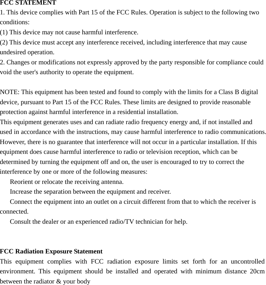
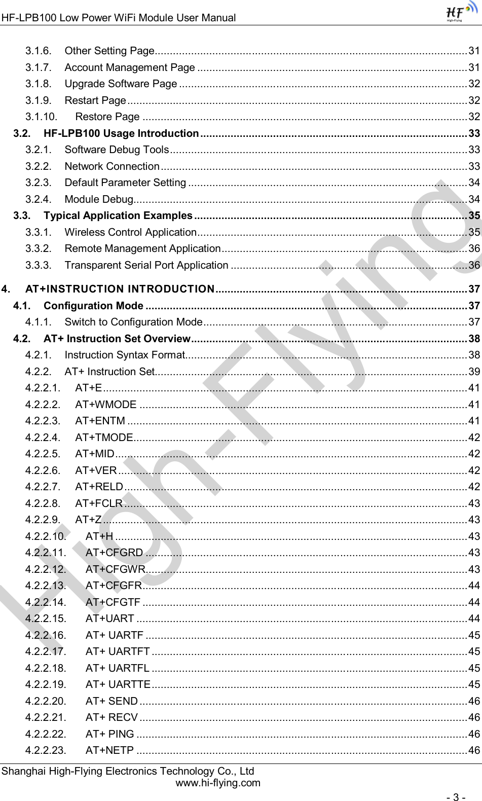
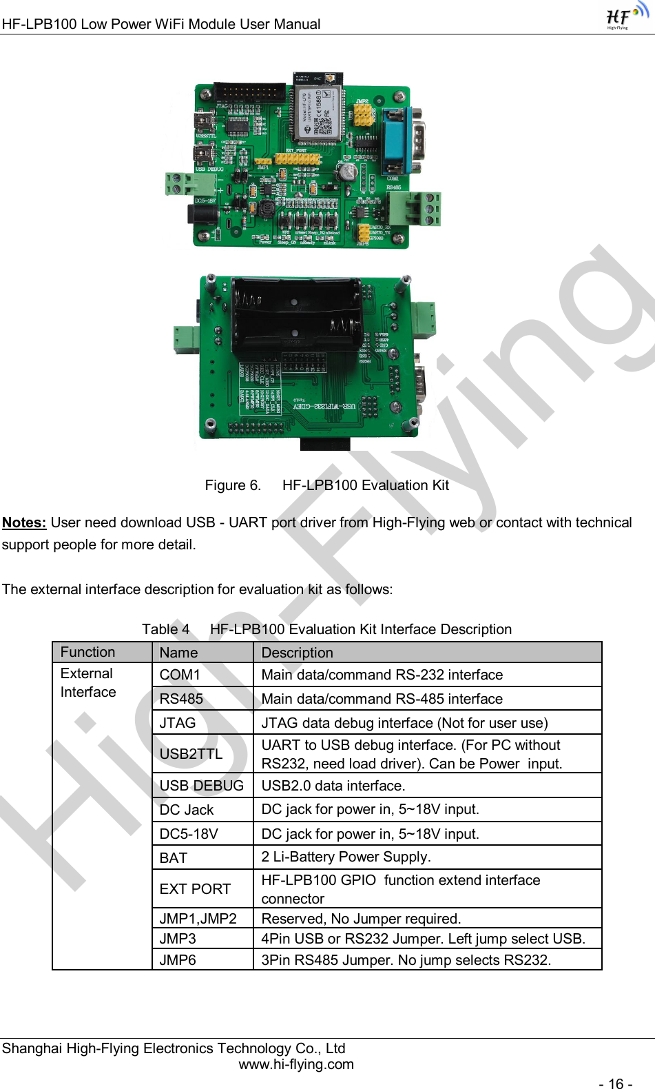
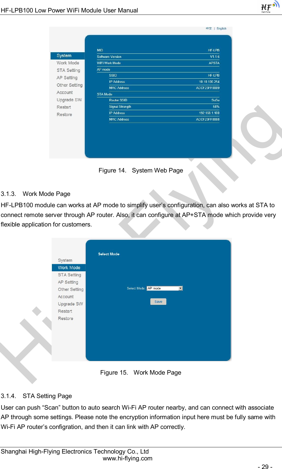
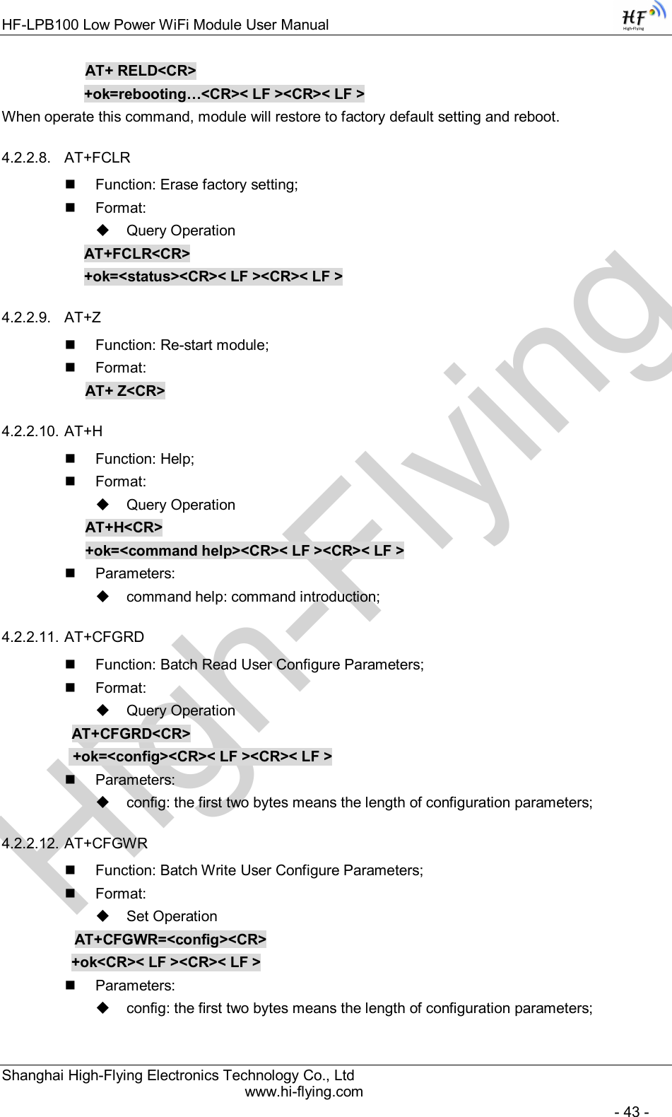
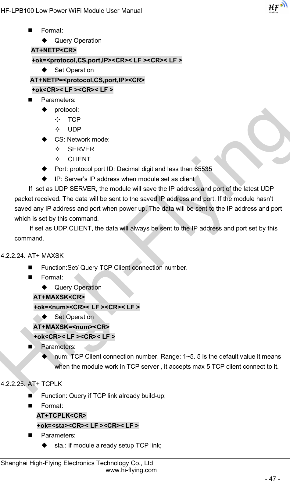
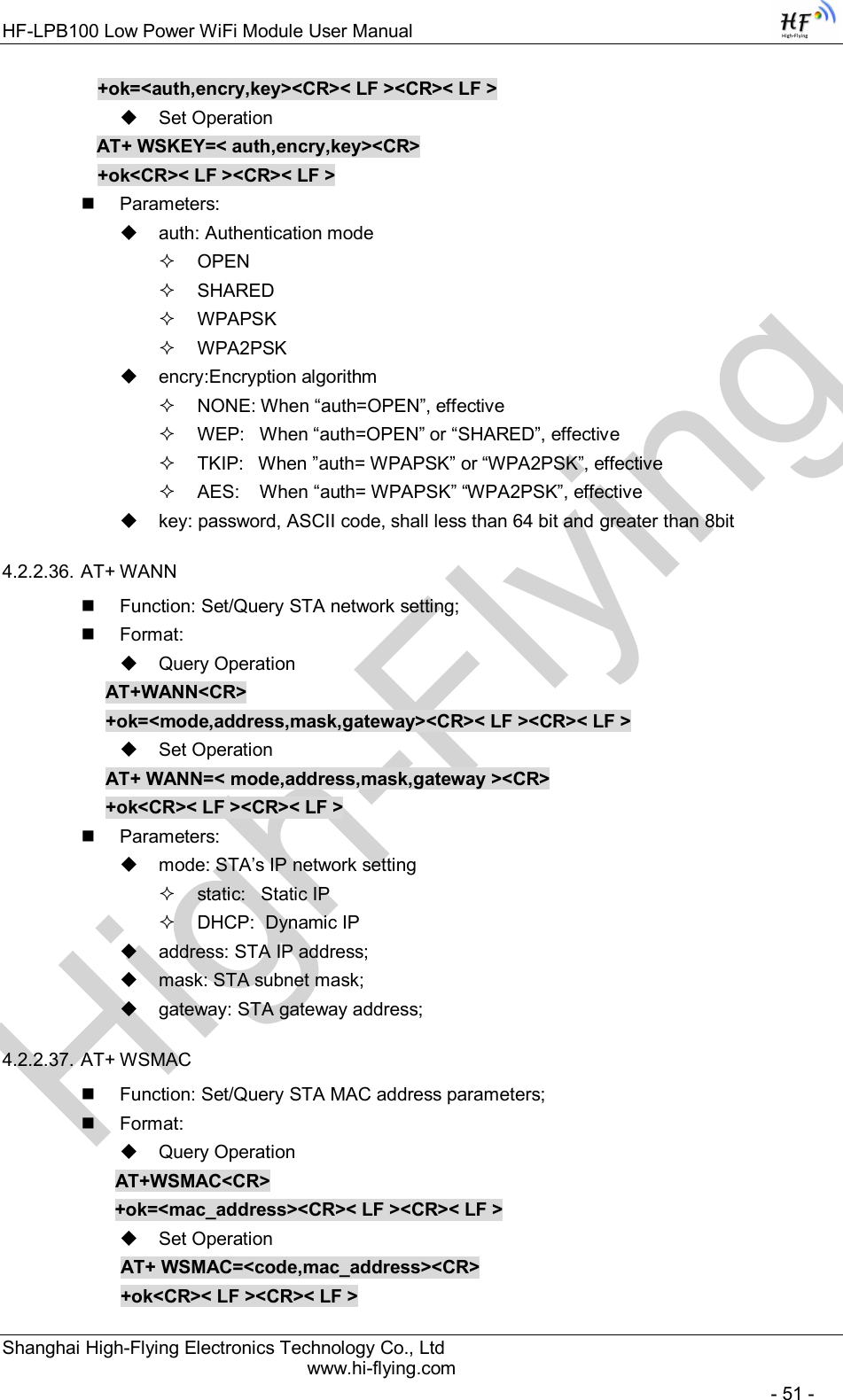
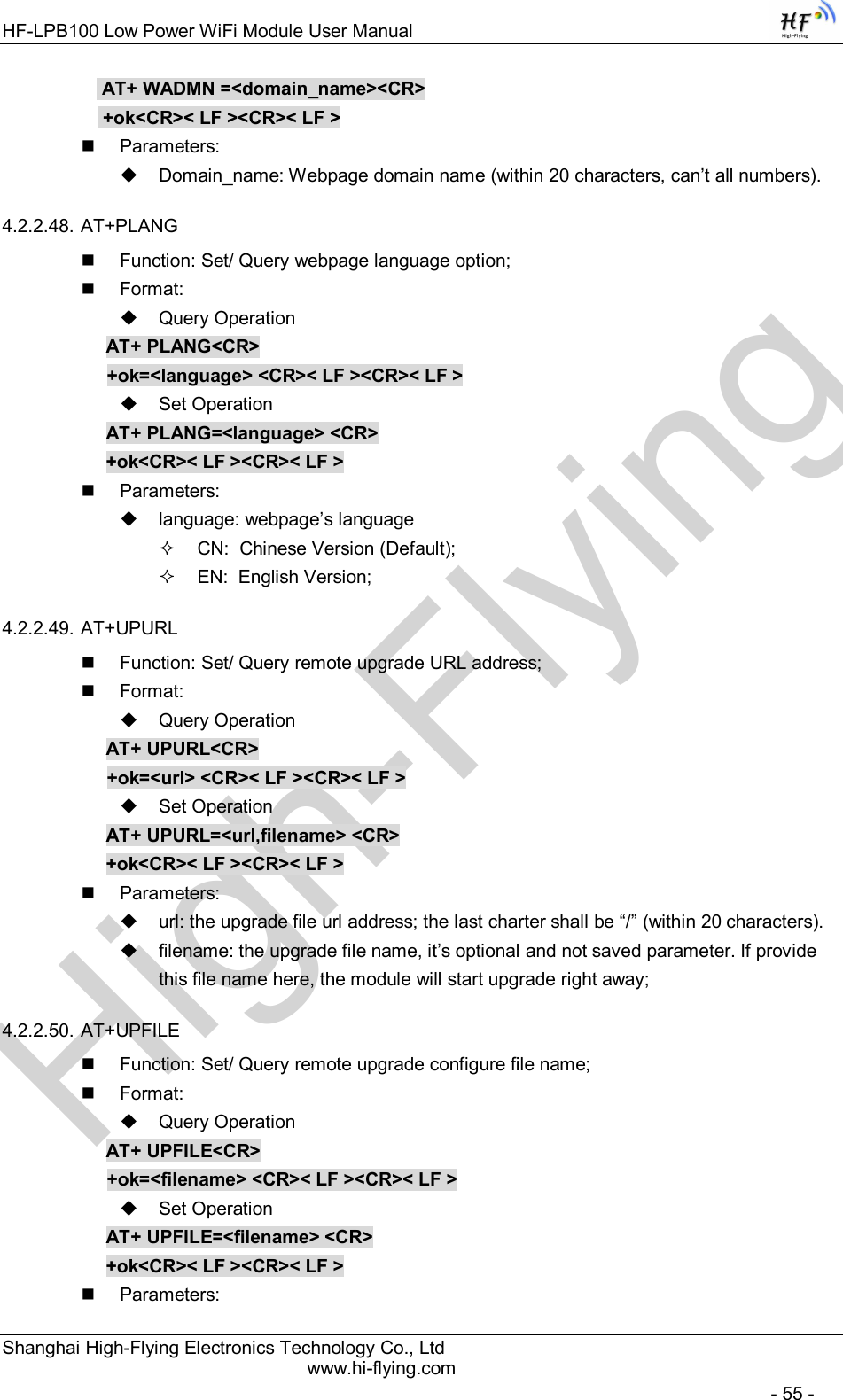
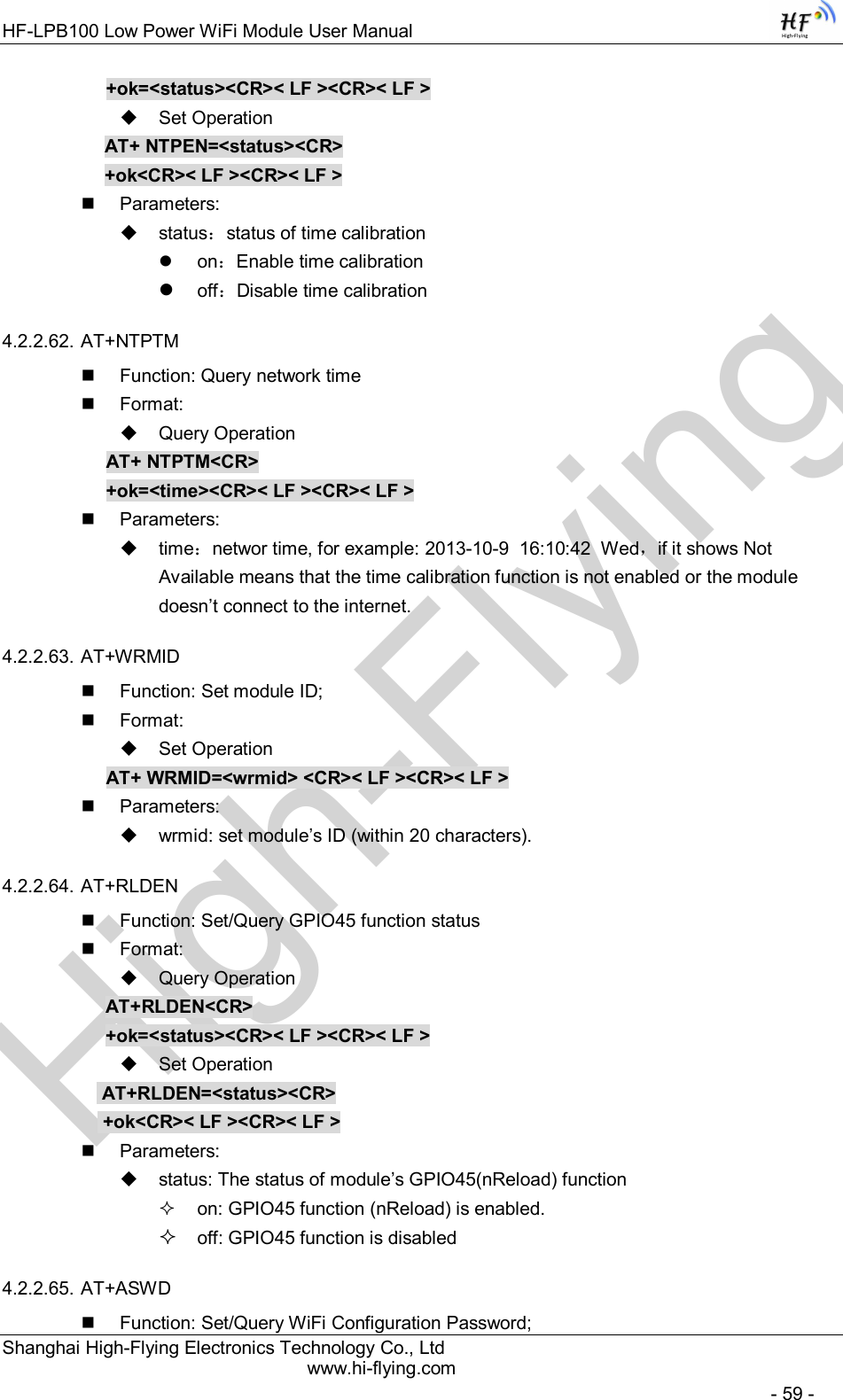
![High-FlyingHF-LPB100 Low Power WiFi Module User Manual Shanghai High-Flying Electronics Technology Co., Ltd www.hi-flying.com - 39 - Notes: When input AT+Instruction, “AT+<CMD>” character will display capital letter automatic and other parts will not change as you input. Response Message +<RSP>[op] [para-1,para-2,para-3,para-4…]<CR><LF><CR><LF> +: Prefix of response message; RSP: Response string; “ok” : Success “ERR”: Failure [op] : = [para-n]: Parameters if query command or Error code when error happened; <CR>: ASCII 0x0d; <LF>: ASCIII 0x0a; Error Code Table 9 Error Code Describtion Error Code Description -1 Invalid Command Format -2 Invalid Command -3 Invalid Operation Symbol -4 Invalid Parameter -5 Operation Not Permitted 4.2.2. AT+ Instruction Set Table 10 AT+ Instruction Set List Instruction Description <null> NULL Managment Instruction Set E Open/Close show back function WMODE Set/Query Wi-Fi work mode (AP/STA/APSTA) ENTM Set module into transparent transition mode TMODE Set/Query module data transfer mode MID Query module ID information VER Query module software version information RELD Restore to factory default setting FCLR Erase factory setting Z Re-start module H Help Configure Parameters Instruction Set CFGRD Batch Read User Configure Parameters CFGWR Batch Write Configure Parameters](https://usermanual.wiki/High-Flying-Electronics-Technology/HF-LPB100.Manual/User-Guide-2150598-Page-39.png)
![High-FlyingHF-LPB100 Low Power WiFi Module User Manual Shanghai High-Flying Electronics Technology Co., Ltd www.hi-flying.com - 60 - Format: Query Operation AT+ ASWD<CR> +ok=<aswd> <CR>< LF ><CR>< LF > Set Operation AT+ ASWD=<aswd> <CR>< LF ><CR>< LF > Parameters: aswd: WiFi Configuration Password (within 20 characters). 4.2.2.66. AT+MDCH Function: Set Wi-Fi Auto Switch Function Format: Query Operation AT+ MDCH<CR> +ok=<mode> <CR>< LF ><CR>< LF > Set Operation AT+ MDCH=<mode> <CR>< LF ><CR>< LF > Parameters: mode: Wi-Fi Auto Switch Mode off: Disable Wi-Fi auto switch. on: Enable Wi-Fi auto switch. When the module(STA mode) fail to connect to router, it will switch to AP mode itself in one minute. auto: Enable Wi-Fi auto detect function. The module will reset itself when encounter any abnormal. The default time interval is 10 minutes. 3-120: unit: minute. Set the time interval to reset itself when abnormal. 4.2.2.67. AT+TXPWR Function: Set/Query Wi-Fi Transmit Power, Real Transmit Power=Default Transmit Power(16dBm) – [Setting Value] * 0.5dBm Format: Query Operation AT+TXPWR <CR> +ok=<num><CR>< LF><CR>< LF> Set Operation AT+TXPWR=<num><CR> +ok<CR>< LF><CR>< LF> Parameters: num: [Setting Value]. The default is 0, it can be sent from 0 ~ 24. If set to 24, the moudule transmit power will be at a minium of 4dBm. Reboot to make this setting change valid. It will not restore to default if reload the module.](https://usermanual.wiki/High-Flying-Electronics-Technology/HF-LPB100.Manual/User-Guide-2150598-Page-60.png)