High Flying Electronics Technology HF-LPB100 Embedded WiFi Module User Manual GPON SFU System Design
High-Flying Electronics Technology Co.,Ltd Embedded WiFi Module GPON SFU System Design
UserManual.wiki
>
High Flying Electronics Technology
>
HF-LPB100 User Manual
>
User manual
Contents
1.
Manual
2.
User manual
User manual
Navigation menu
Upload a User Manual
Namespaces
Wiki Guide
HTML
PDF
Info
Views
User Manual
Discussion / Help
Navigation
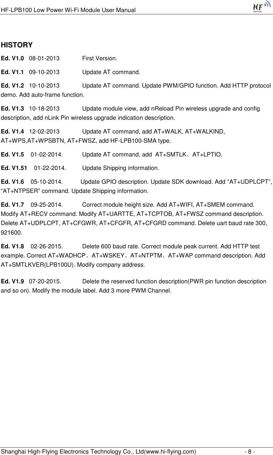
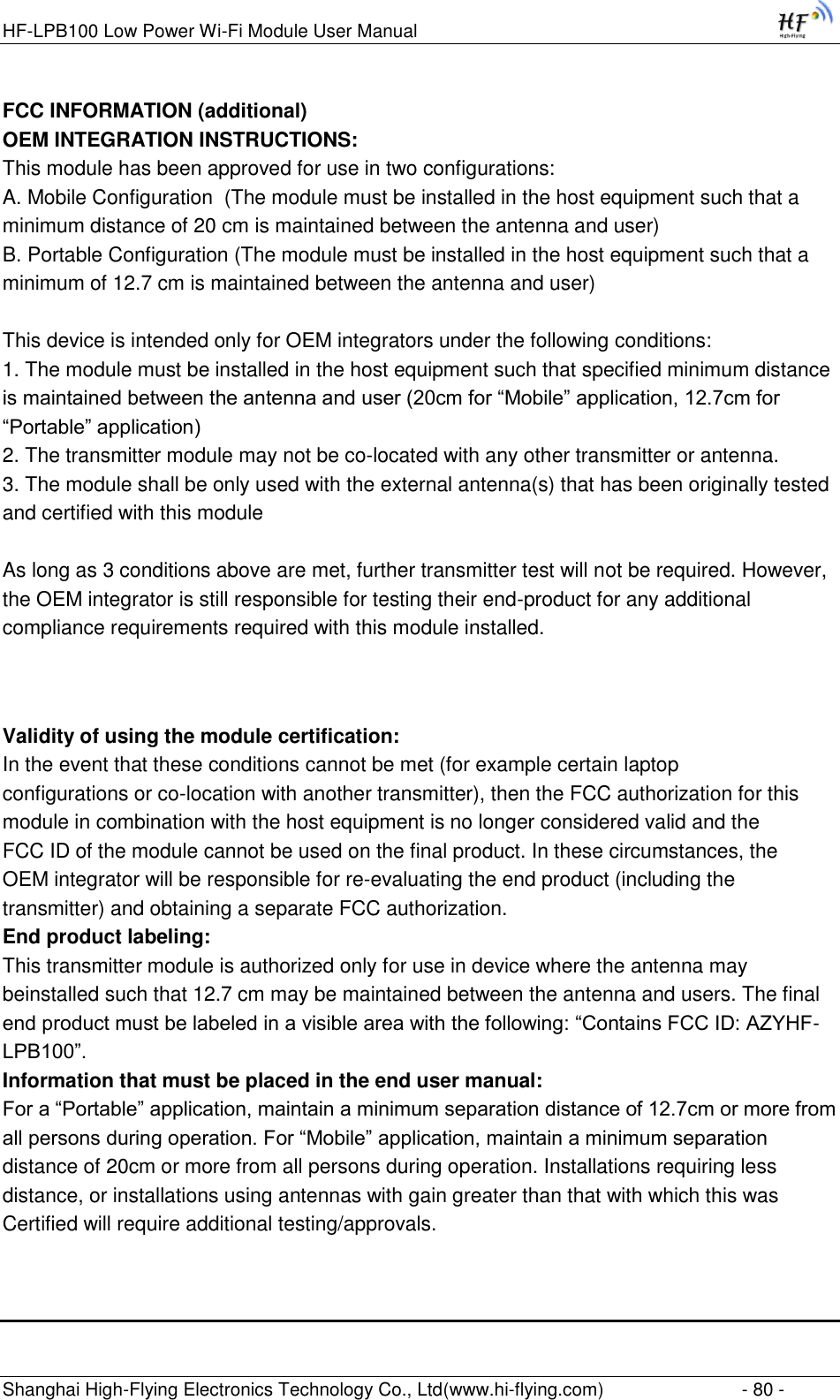
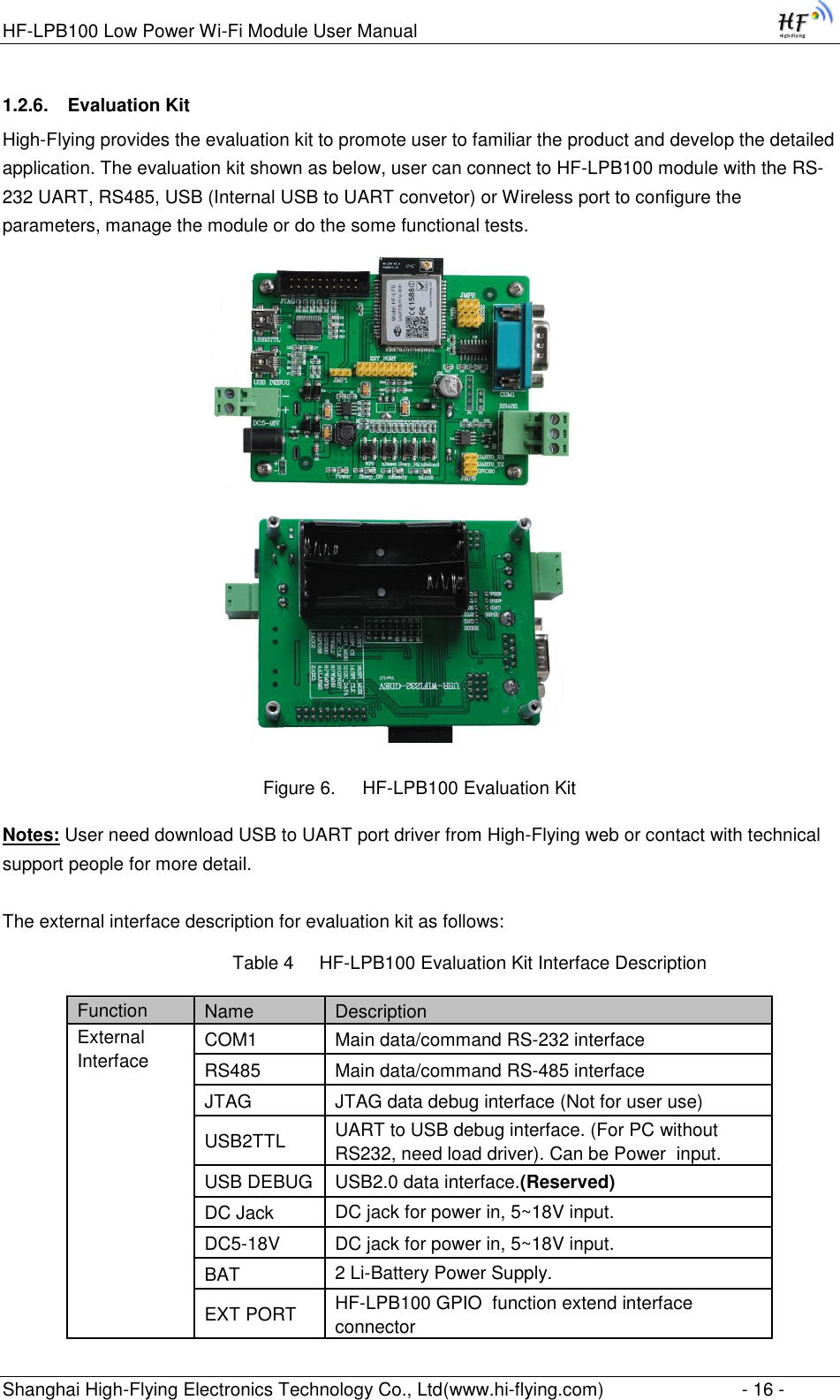
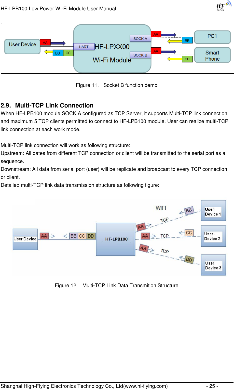
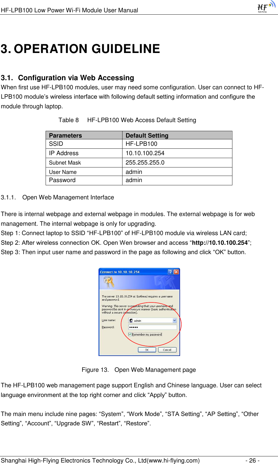
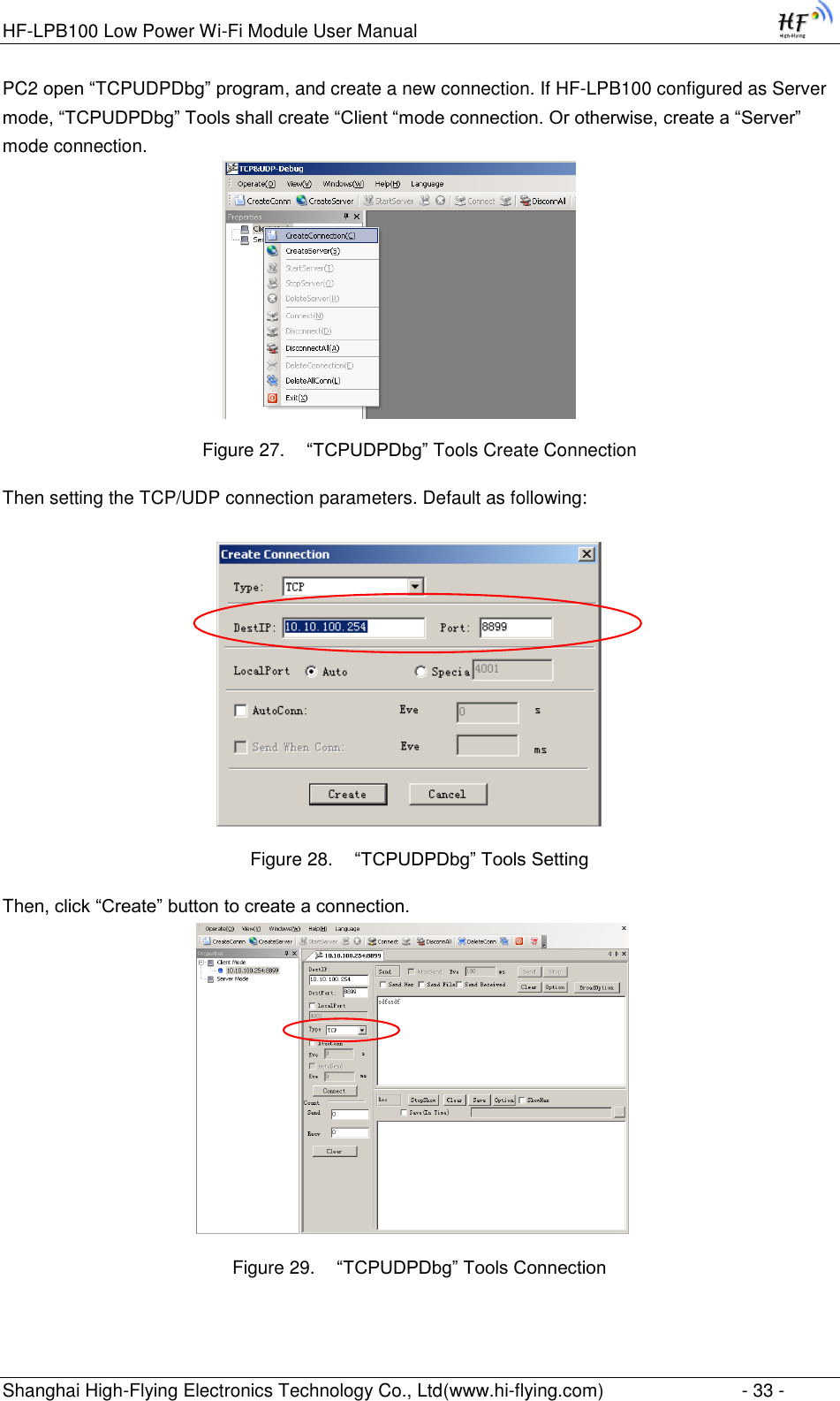
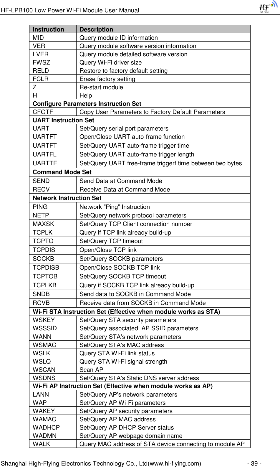
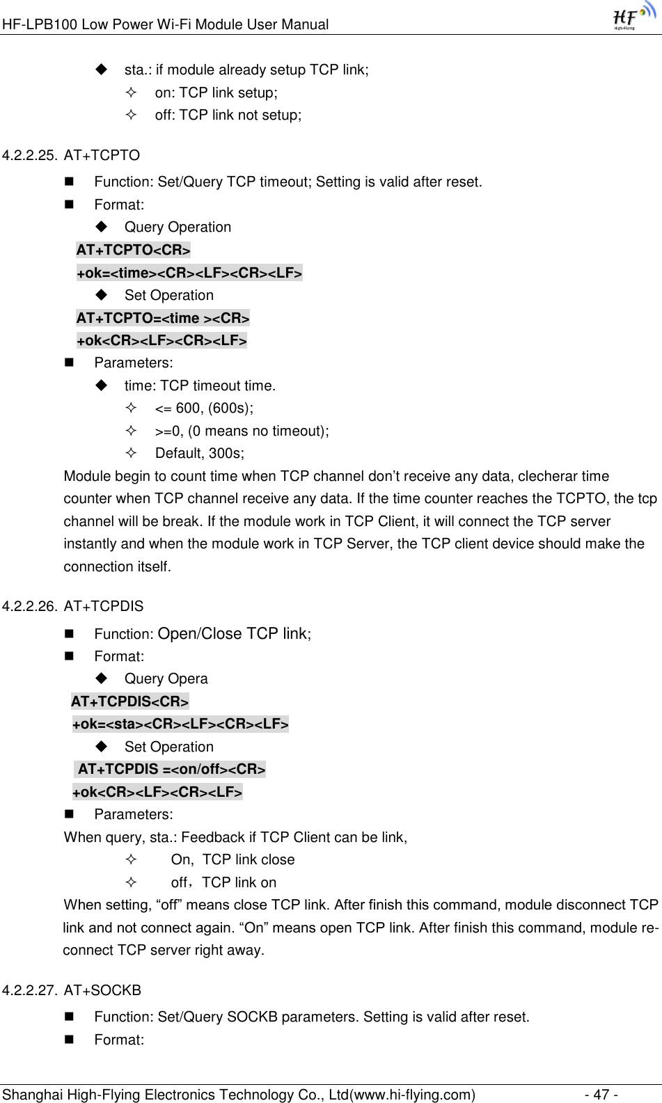
![HF-LPB100 Low Power Wi-Fi Module User Manual Shanghai High-Flying Electronics Technology Co., Ltd(www.hi-flying.com) - 10 - 1.1.2 Device Paremeters Table 1 HF-LPB100 Module Technical Specifications Class Item Parameters Wireless Parameters Certification FCC/CE Wireless standard 802.11 b/g/n Frequency range 2.412GHz-2.484GHz Transmit Power 802.11b +17dBm (@11mbps) 802.11g +22dBm (@54mbps) 802.11n +22dBm (@HT20 MCS7) Receiver Sensitivity 802.11b: -93 dBm (@11Mbps ,CCK) 802.11g: -85 dBm (@54Mbps, OFDM) 802.11n: -82 dBm (@HT20, MCS7) Antenna Option External:I-PEX Connector or SMA connector Internal:On-board PCB antenna Hardware Parameters Data Interface UART SPI, PWM, GPIO Operating Voltage 2.8~3.6V Operating Current Peak [Continuous TX]: ~300mA Normal [WiFi ON/OFF, DTIM=100ms]: Average. ~12mA, Peak: 300mA Operating Temp. -40℃- 85℃ Storage Temp. -45℃- 125℃ Dimensions and Size 23.1mm×32.8mm×(3.45±0.3)mm Software Parameters Network Type STA /AP/STA+AP Security Mechanisms WEP/WPA-PSK/WPA2-PSK Encryption WEP64/WEP128/TKIP/AES Update Firmware Local Wireless, Remote Customization Web Page Upgrade Support SDK for application develop Network Protocol IPv4, TCP/UDP/HTTP User Configuration AT+instruction set. Android/ iOS Smart Link APP tools 1.1.3 Key Application Remote equipment monitoring Asset tracking and telemetry Security Industrial sensors and controls Home automation Medical devices](https://usermanual.wiki/High-Flying-Electronics-Technology/HF-LPB100.User-manual/User-Guide-3019987-Page-10.png)
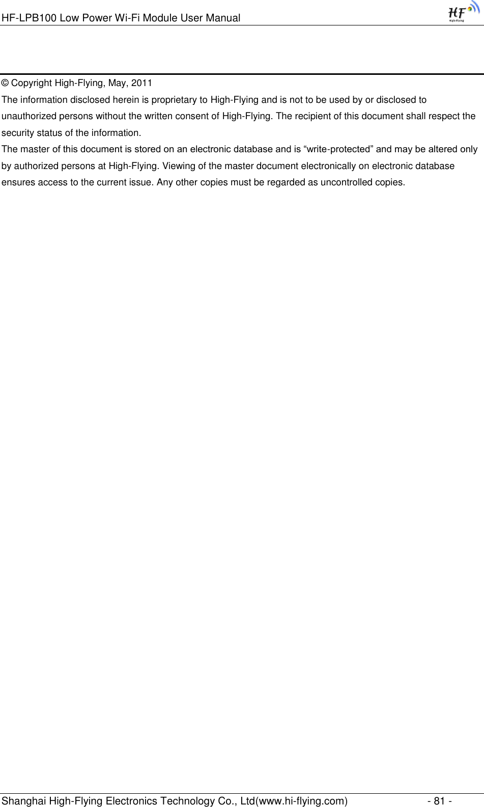
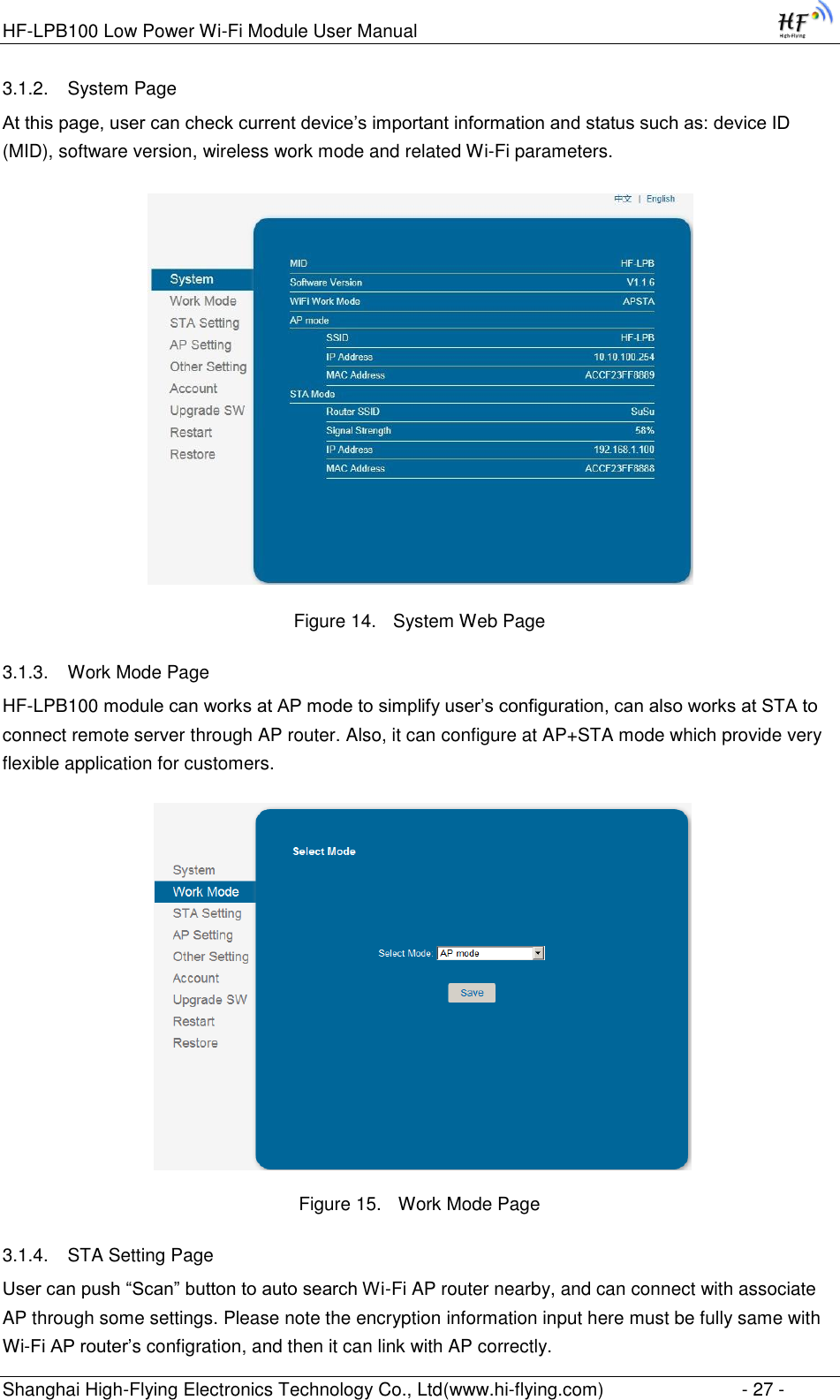
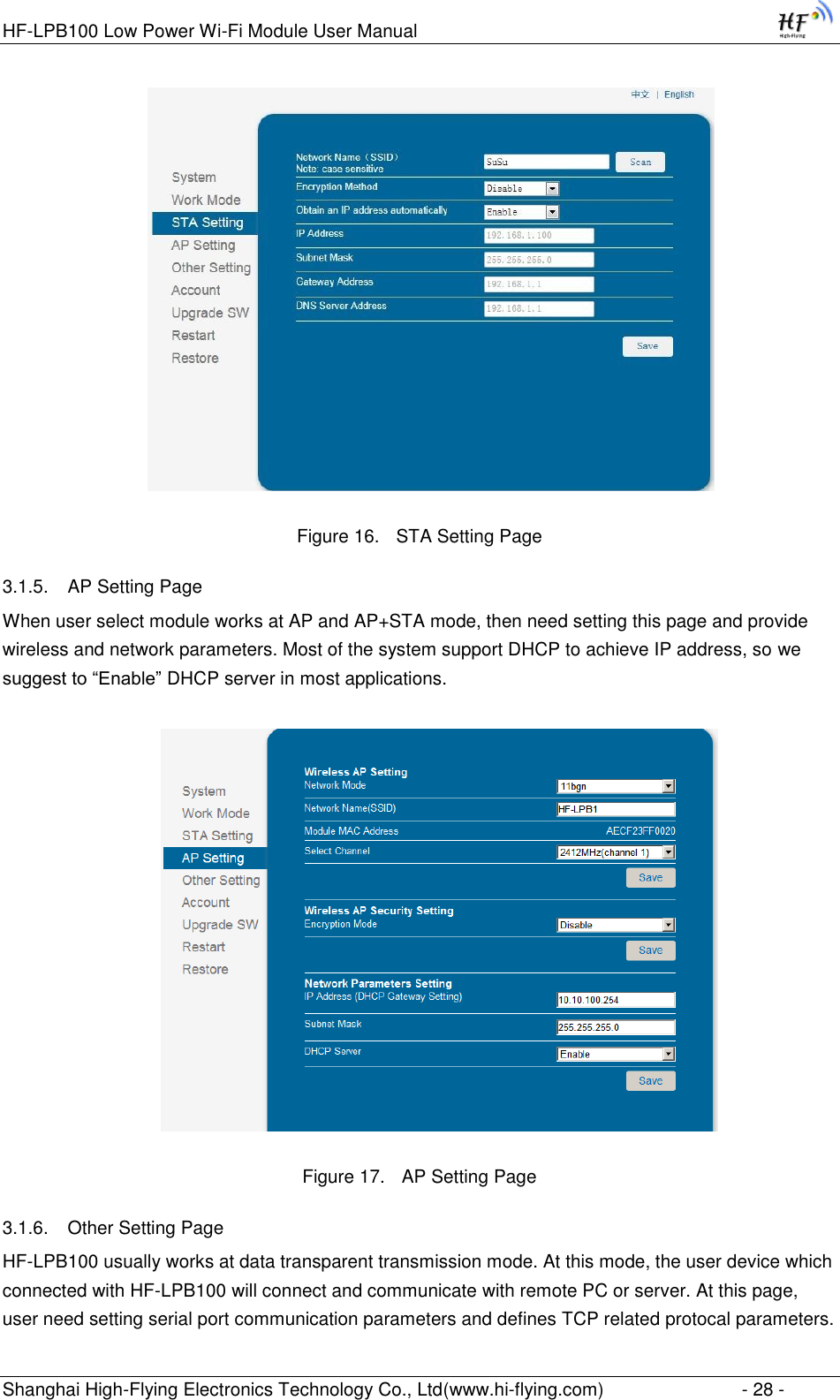
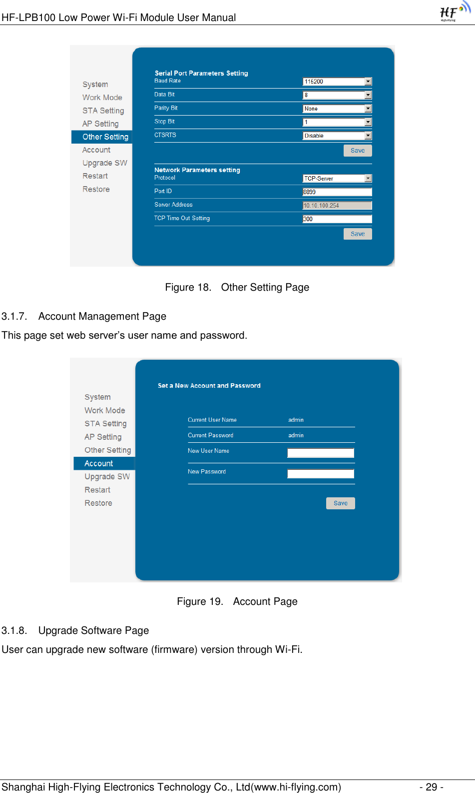
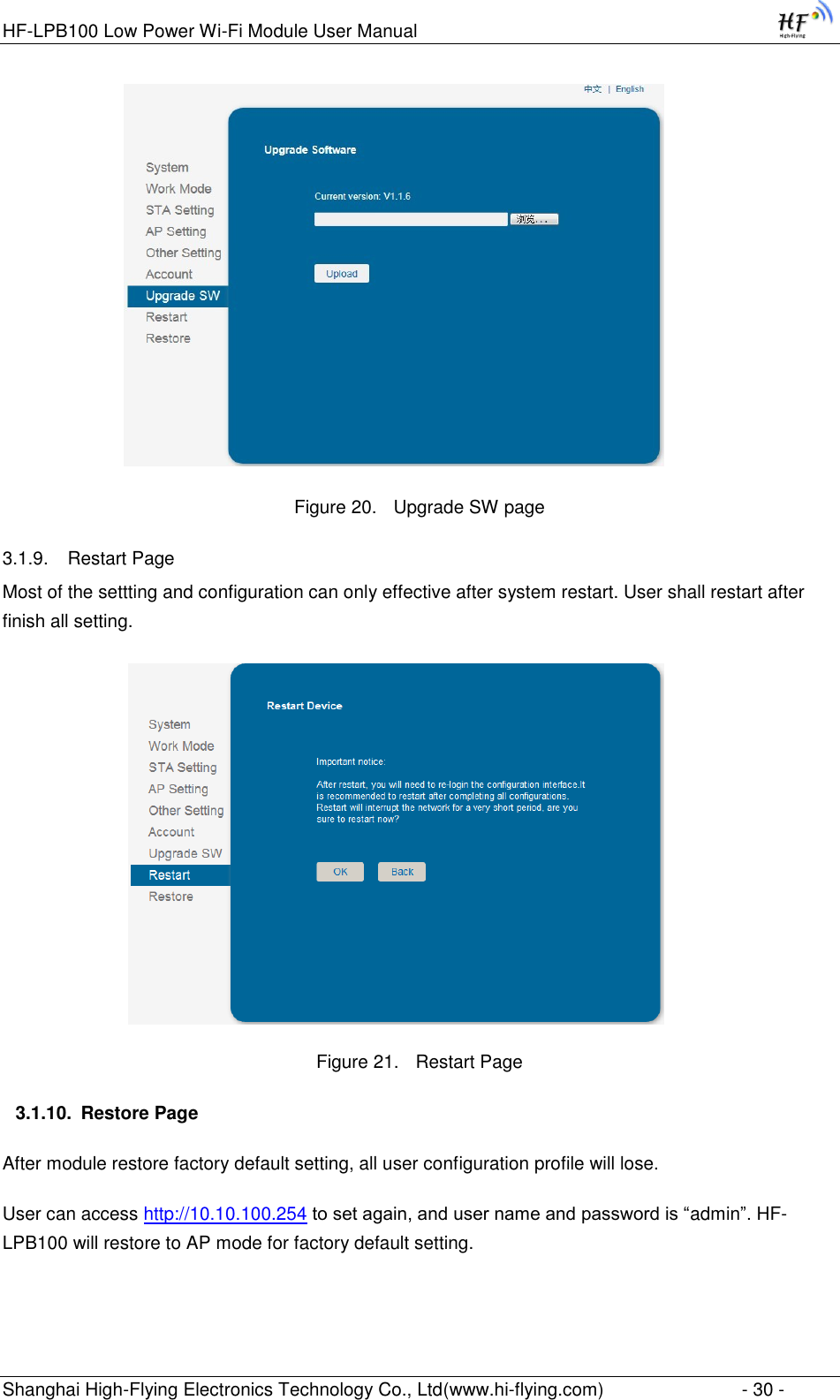
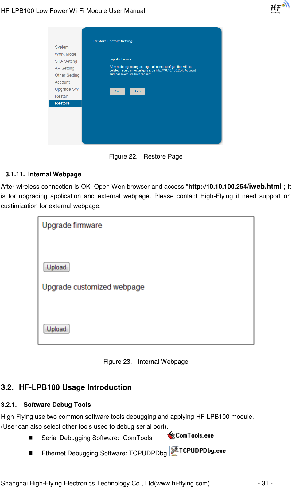
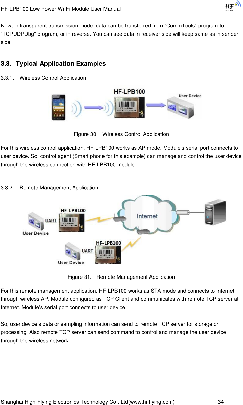
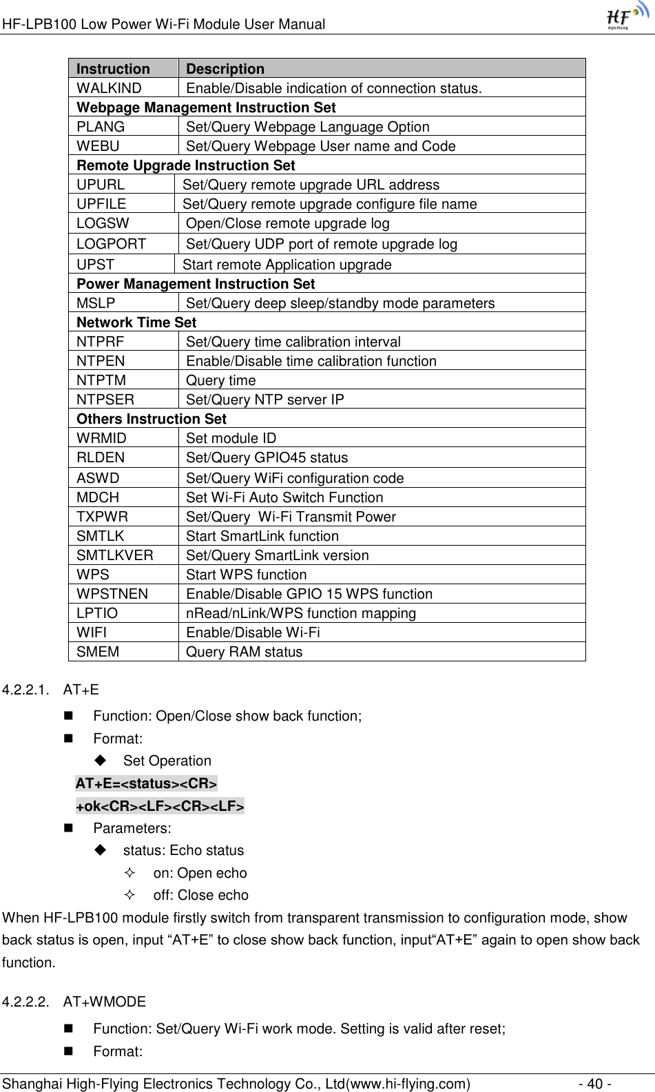
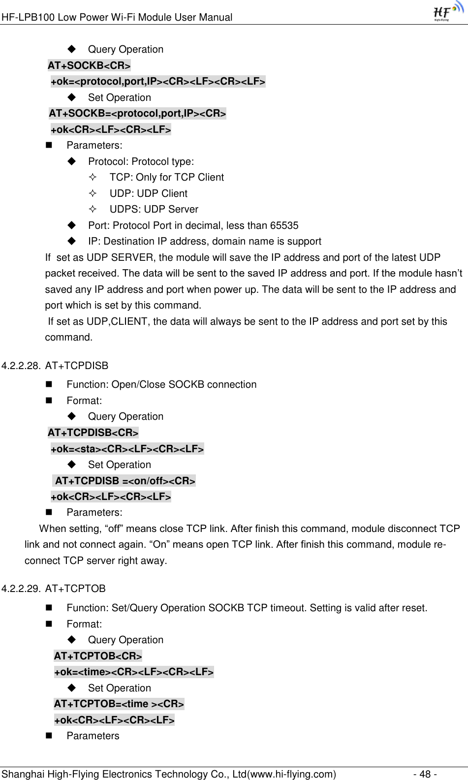
![HF-LPB100 Low Power Wi-Fi Module User Manual Shanghai High-Flying Electronics Technology Co., Ltd(www.hi-flying.com) - 23 - 2.4. Encryption Encryption is a method of scrambling a message that makes it unreadable to unwanted parties, adding a degree of secure communications. There are different protocols for providing encryption, and the HF-LPB100 module supports following: WEP WPA-PSK/TKIP WPA-PSK/AES WPA2-PSK/TKIP WPA2-PSK/AES 2.5. Parameters Configuration HF-LPB100 module supports two methods to configuration parameters: Web Accessing and AT+instruction set. Web accessing means users can configure parameters through Web browser. When HF-LPB100 module connected to wireless network, parameters configuration is done on a PC connected to the same wireless network. AT+instruction set configuration means user configure parameters through serial interface command. Refer to “AT+instruction set” chapter for more detail. 2.6. Firmware Update HF-LPB100 module supports two on-line upgrade methods: Webpage Wi-Fi Upgrade Remote Upgrade Webpage based Wi-Fiupgrade,please refer to 3.1.8 firmware upgrade page , user can upload firmware file from PC to HF-LPB100. HF-LPB100 module also support upgrade from remote HTTP server, keep module connects to AP router before excute remote HTTP upgrade. Remote upgrade have two methods: Direct Download and Upgrade, Configure File Based Upgrade. Configure File Based Upgrade AT+UPURL command to set the remote directory which the configuration file located, such as AT+UPURL=http://www.hi-flying.com/!admin/down/ Notes: The last ‟/‟ can‟t be remove AT+UPFILE command to set the configuration file name, such as AT+UPFILE=config.txt AT+UPST command to start remote Application upgrade. After excuate this command, the module will firstly download configuration file (“config.txt”), then download the upgrade file base on the URL address listed in the configure file. General “config.txt” file format as following example: [URL]=http://10.10.100.100:80/lpb.bin [URL]= the URL address of Application.](https://usermanual.wiki/High-Flying-Electronics-Technology/HF-LPB100.User-manual/User-Guide-3019987-Page-23.png)
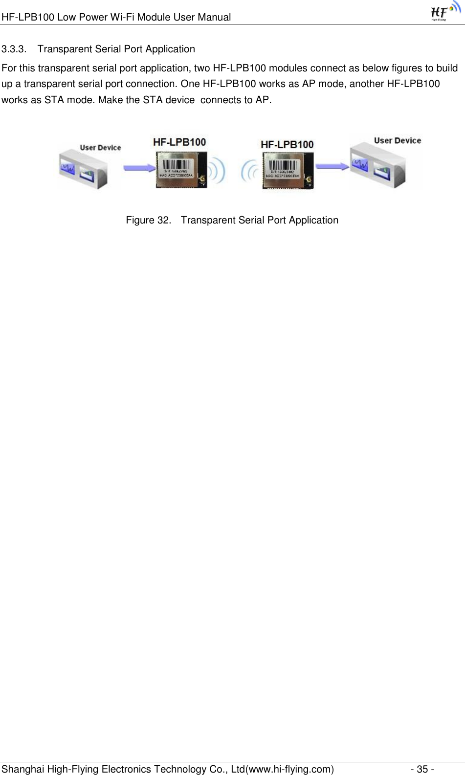
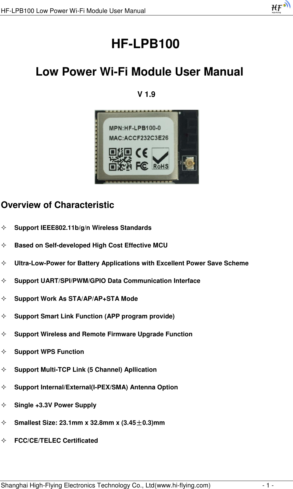
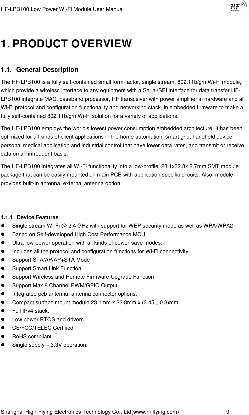
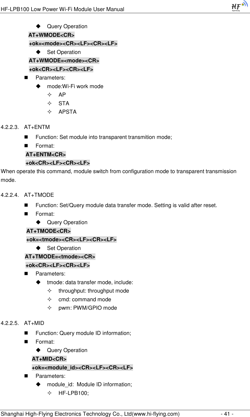
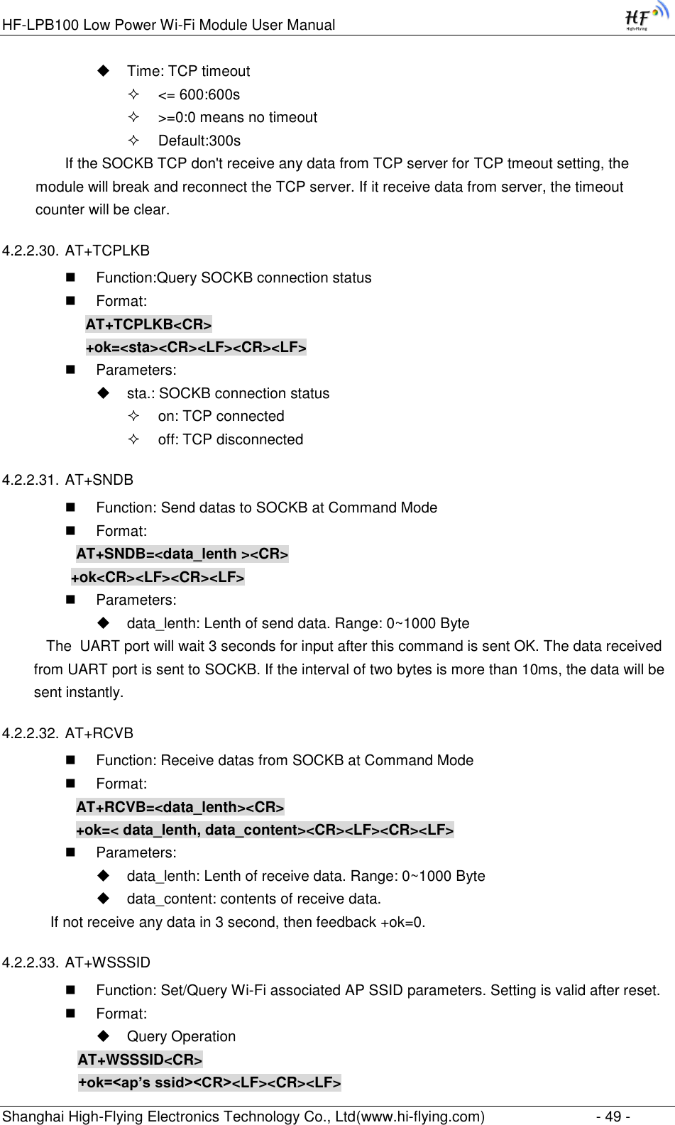
![HF-LPB100 Low Power Wi-Fi Module User Manual Shanghai High-Flying Electronics Technology Co., Ltd(www.hi-flying.com) - 37 - 2. Any other input or wrong step to UART port will cause the module still works as original mode (transparent transmission). 3. “+++” and “a” should be input in a certain period of time to make the module switch to configuration mode. Like the following sequence. 4.2. AT+Instruction Set Overview User can input AT+Instruction through hyper terminal or other serial debug terminal, also can program the AT+Instruction to script. User can also input “AT+H” to list all AT+Instruction and description to start. Figure 35. ”AT+H” Instruction for Help 4.2.1. Instruction Syntax Format AT+Instruction protocol is based on the instruction of ASCII command style, the description of syntax format as follow. Format Description < >: Means the parts must be included [ ]: Means the optional part Command Message](https://usermanual.wiki/High-Flying-Electronics-Technology/HF-LPB100.User-manual/User-Guide-3019987-Page-37.png)
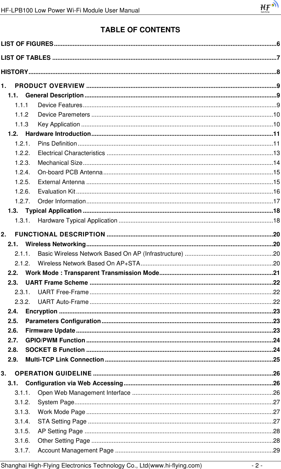
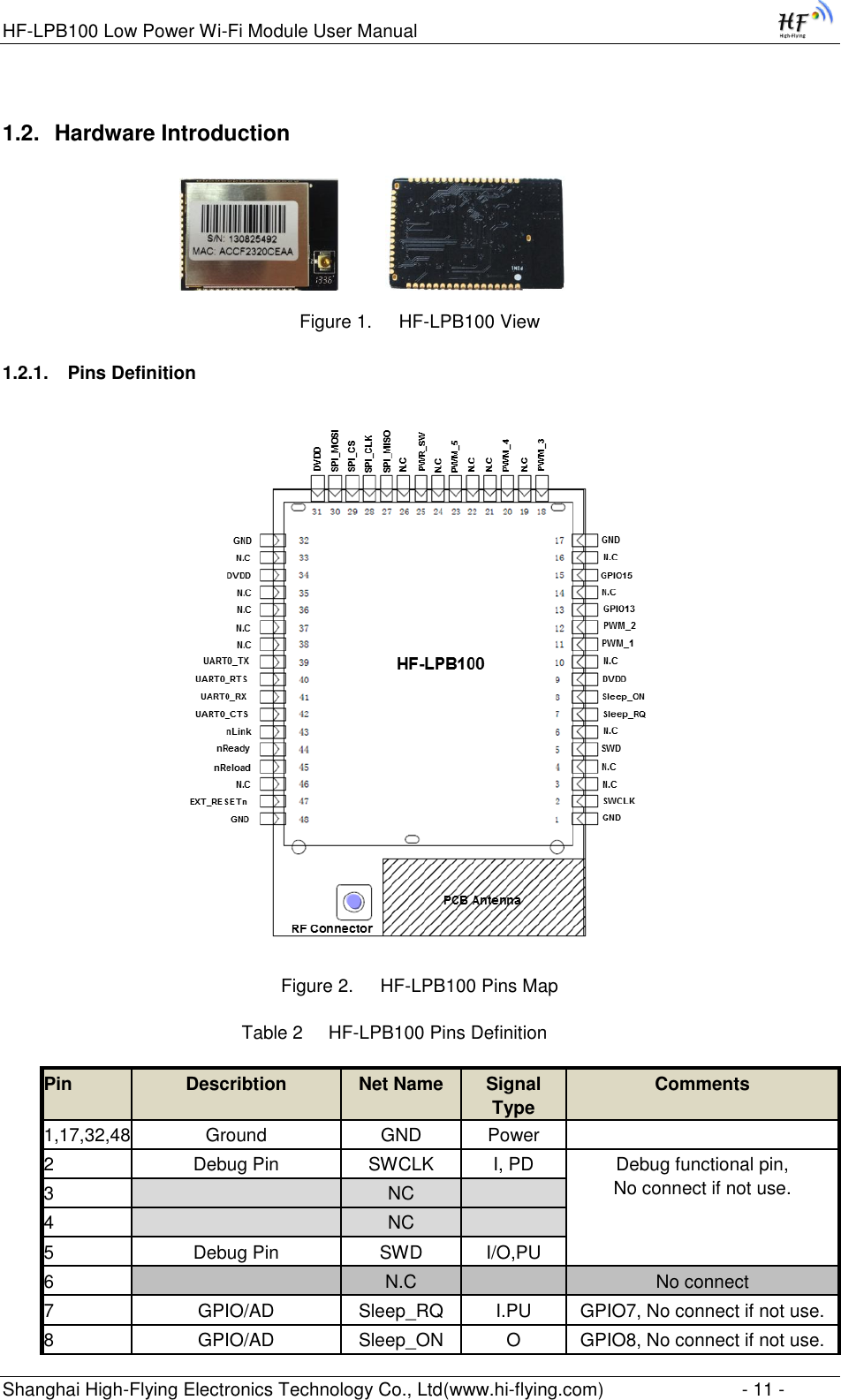
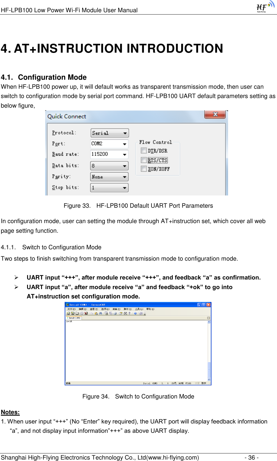
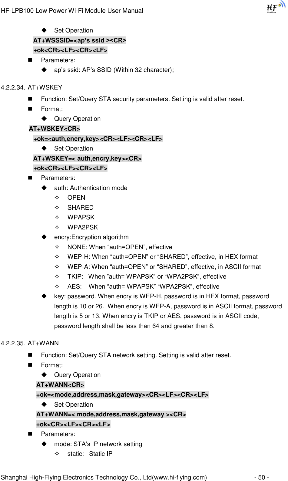
![HF-LPB100 Low Power Wi-Fi Module User Manual Shanghai High-Flying Electronics Technology Co., Ltd(www.hi-flying.com) - 38 - AT+<CMD>[op][para-1,para-2,para-3,para-4…]<CR> AT+: Prefix of command message; CMD: Command string; [op]: Symbol of command operator, “=” : The command requires parameters input; “NULL”: Query the current command parameters setting; [para-n]: Parameters input for setting if required; <CR>:”Enter” Key, it‟s 0x0a or 0x0d in ASCII; Notes: When input AT+Instruction, “AT+<CMD>” character will display capital letter automatic and other parts will not change as you input. Response Message +<RSP>[op] [para-1,para-2,para-3,para-4…]<CR><LF><CR><LF> +: Prefix of response message; RSP: Response string; “ok” : Success “ERR”: Failure [op] : = [para-n]: Parameters if query command or Error code when error happened; <CR>: ASCII 0x0d; <LF>: ASCIII 0x0a; Error Code Table 9 Error Code Describtion Error Code Description -1 Invalid Command Format -2 Invalid Command -3 Invalid Operation Symbol -4 Invalid Parameter -5 Operation Not Permitted 4.2.2. AT+Instruction Set Table 10 AT+Instruction Set List Instruction Description <null> NULL Managment Instruction Set E Open/Close show back function WMODE Set/Query Wi-Fi work mode (AP/STA/APSTA) ENTM Set module into transparent transition mode TMODE Set/Query module data transfer mode](https://usermanual.wiki/High-Flying-Electronics-Technology/HF-LPB100.User-manual/User-Guide-3019987-Page-38.png)
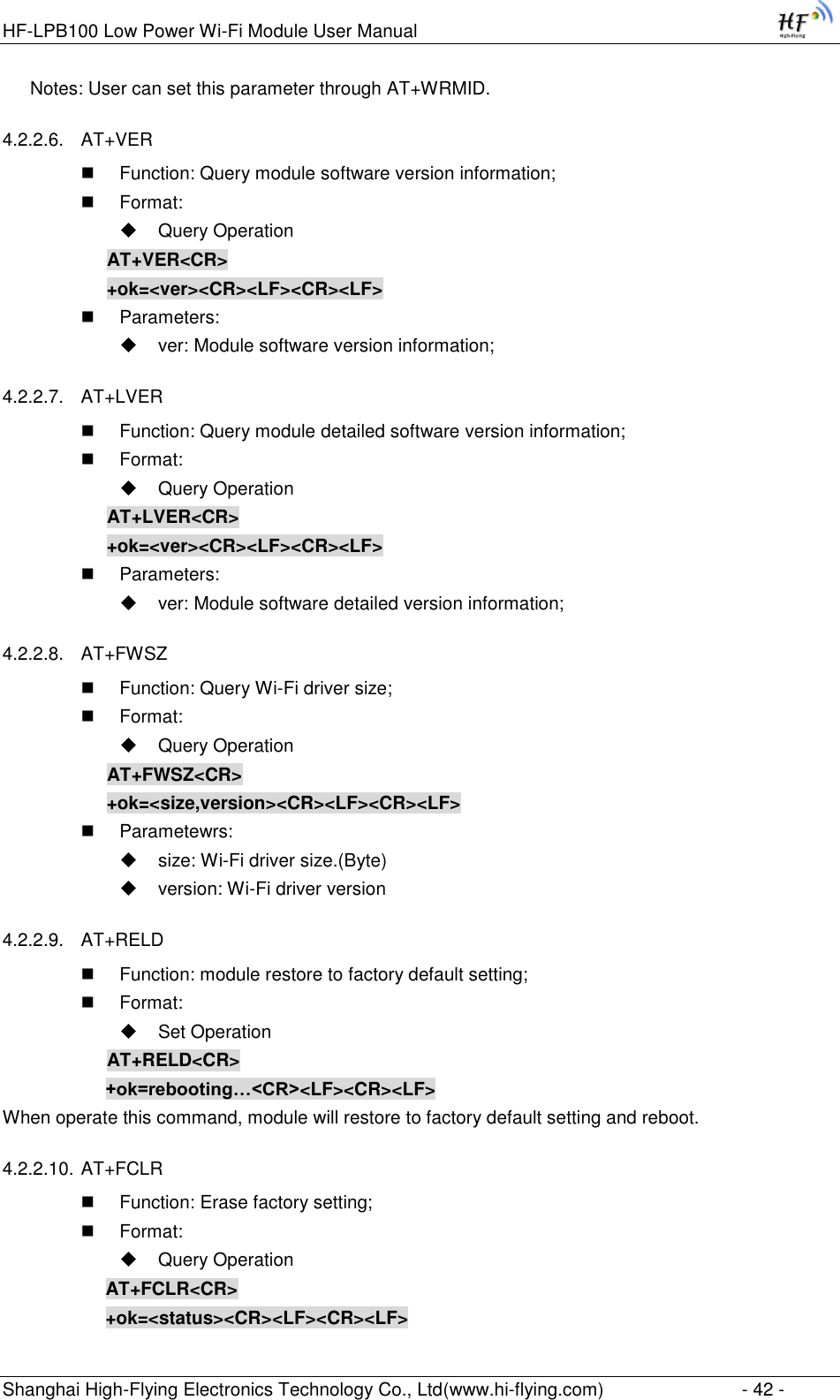
![HF-LPB100 Low Power Wi-Fi Module User Manual Shanghai High-Flying Electronics Technology Co., Ltd(www.hi-flying.com) - 53 - channel: Wi-Fi channel selection: AUTO;(Default CH1) CH1~CH11; 4.2.2.43. AT+WAKEY Function: Set/Query AP Wi-Fi secruity parameters. Setting is valid after reset. Format: Query Operation AT+WAKEY<CR> +ok=<auth,encry,key><CR><LF><CR><LF> Set Operation AT+WAKEY=< auth,encry,key><CR> +ok<CR><LF><CR><LF> Parameters: auth: include OPEN WPA2PSK Encry: include NONE: When “auth=OPEN” available; AES: When “auth=WPA2PSK” available; key: security code, ASCII code, smaller than 64bit and bigger than 8 bit; 4.2.2.44. AT+WAMAC Function: Query AP MAC address parameters; Format: Query Operation AT+WAMAC<CR> +ok=<mac_address><CR><LF><CR><LF> Parameters: mac_address:AP‟s MAC address; Note: Module AP mode‟s MAC address is related to STA mode‟s MAC address. If user need changeto others, please contact with high-flying technical people. 4.2.2.45. AT+WADHCP Function: Set/Query AP DHCP server status; Setting is valid after reset. Format: Query Operation AT+WADHCP<CR> +ok=<status>,<ip1>,<ip2><CR><LF><CR><LF> Set Operation AT+WADHCP=<status>[,ip1,ip2]<CR> +ok<CR><LF><CR><LF> Parameters: status:AP‟s DHCP server function status:](https://usermanual.wiki/High-Flying-Electronics-Technology/HF-LPB100.User-manual/User-Guide-3019987-Page-53.png)
![HF-LPB100 Low Power Wi-Fi Module User Manual Shanghai High-Flying Electronics Technology Co., Ltd(www.hi-flying.com) - 59 - Format: Query Operation AT+ASWD<CR> +ok=<aswd> <CR><LF><CR><LF> Set Operation AT+ASWD=<aswd> <CR><LF><CR><LF> Parameters: aswd: WiFi Configuration Password (within 20 characters). 4.2.2.64. AT+MDCH Function: Set Wi-Fi Auto Switch Function. Setting is valid after reset. Format: Query Operation AT+MDCH<CR> +ok=<mode> <CR><LF><CR><LF> Set Operation AT+MDCH=<mode> <CR><LF><CR><LF> Parameters: mode: Wi-Fi Auto Switch Mode off: Disable Wi-Fi auto switch. on: Enable Wi-Fi auto switch. When the module(STA mode) fail to connect to router, it will switch to AP mode itself in one minute. auto: Enable Wi-Fi auto detect function. The module will reset itself when encounter any abnormal. The default time interval is 10 minutes. (default mode) 3-120: unit: minute. Set the time interval to reset itself when abnormal. 4.2.2.65. AT+TXPWR Function: Set/Query Wi-Fi Transmit Power, Real Transmit Power=Default Transmit Power(16dBm) – [Setting Value] * 0.5dBm. Setting is valid after reset. Format: Query Operation AT+TXPWR <CR> +ok=<num><CR><LF><CR><LF> Set Operation AT+TXPWR=<num><CR> +ok<CR><LF><CR><LF> Parameters: num: [Setting Value]. The default is 0, it can be sent from 0 ~ 24. If set to 24, the moudule transmit power will be at a minium of 4dBm. Reboot to make this setting change valid. It will not restore to default if reload the module. 4.2.2.66. AT+SMTLK Function: Start SmartLink function](https://usermanual.wiki/High-Flying-Electronics-Technology/HF-LPB100.User-manual/User-Guide-3019987-Page-59.png)