High Flying Electronics Technology HF-LPB200 WiFi Module User Manual GPON SFU System Design
High-Flying Electronics Technology Co.,Ltd WiFi Module GPON SFU System Design
UserManual.wiki
>
High Flying Electronics Technology
>
HF-LPB200 User Manual
>
Manual
Contents
1.
Manual
2.
Addendum
Manual
Navigation menu
Upload a User Manual
Namespaces
Wiki Guide
HTML
PDF
Info
Views
User Manual
Discussion / Help
Navigation
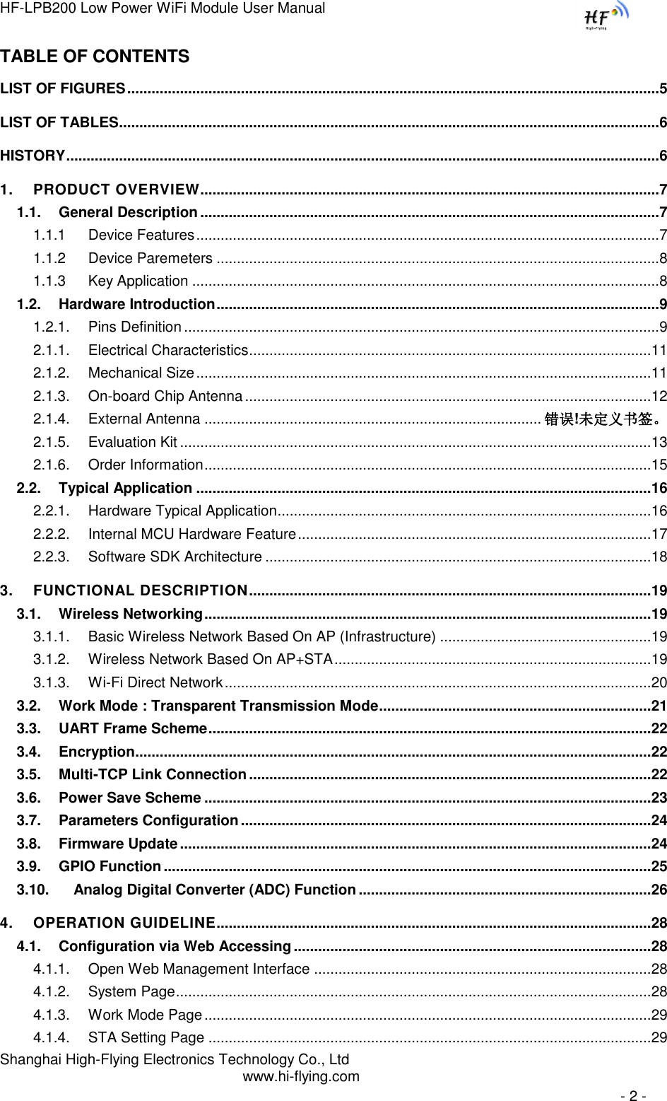
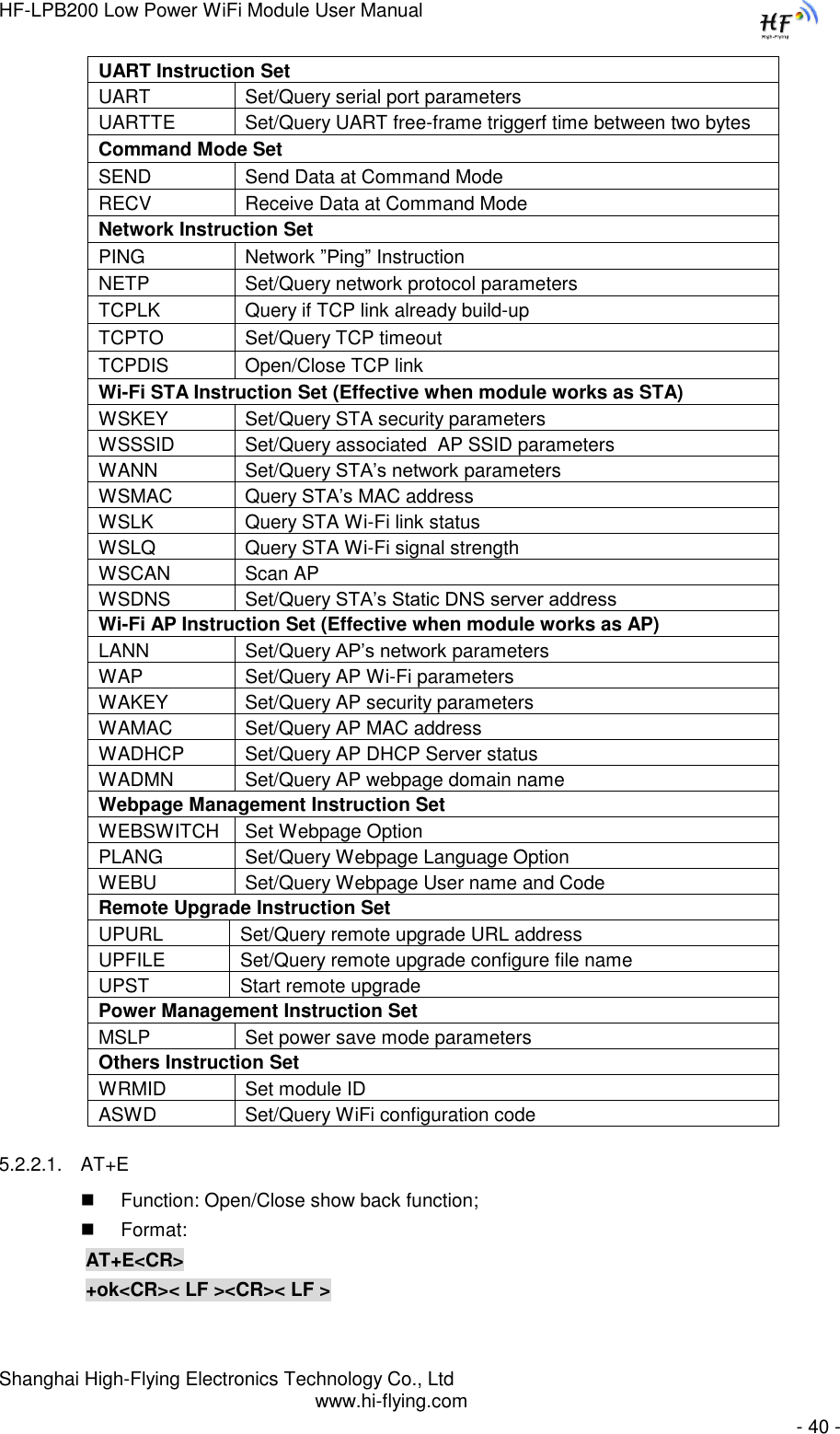
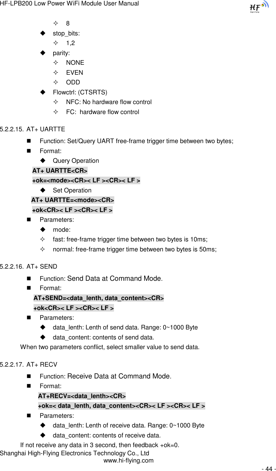
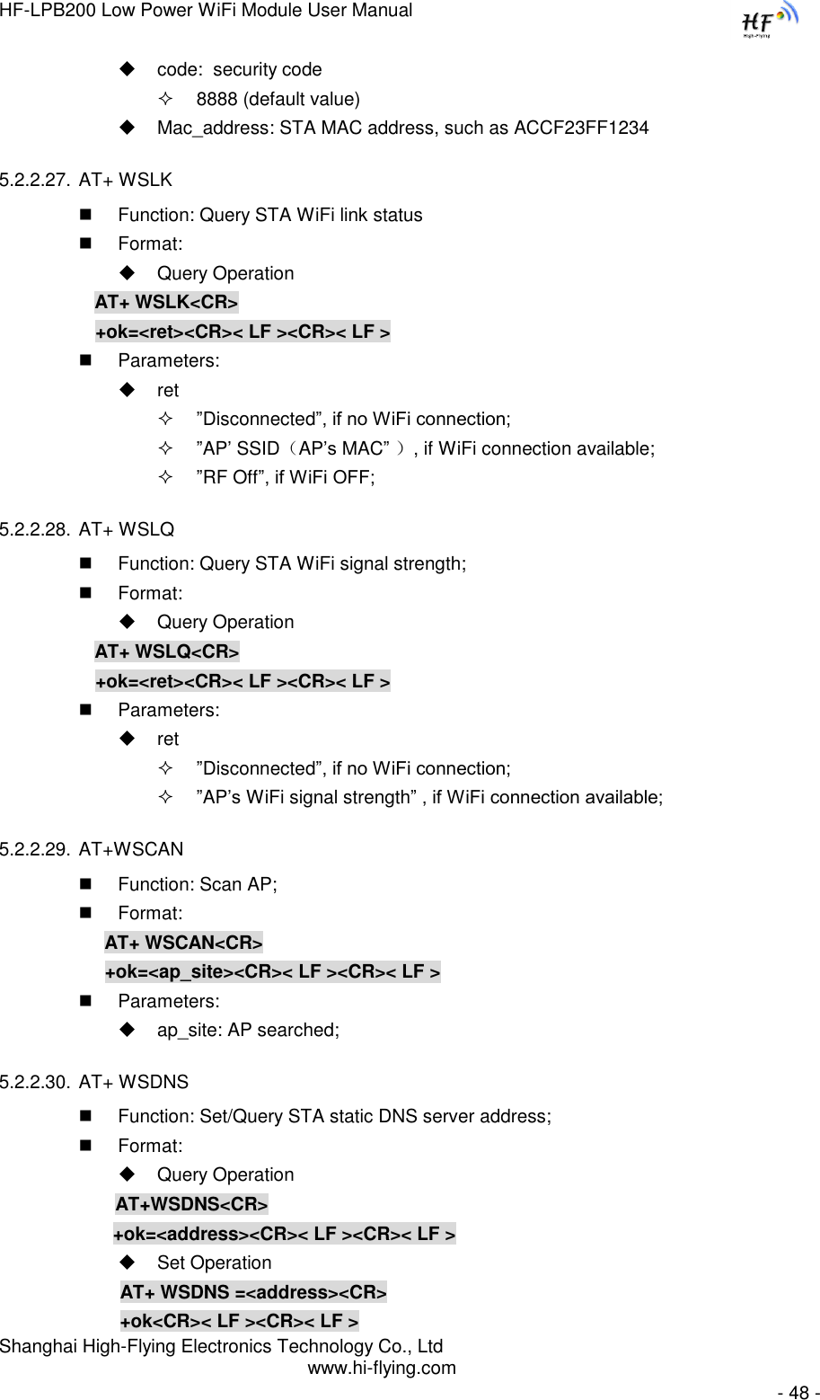
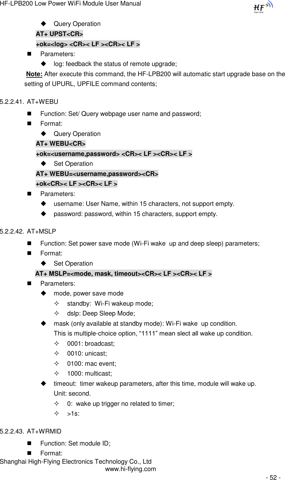
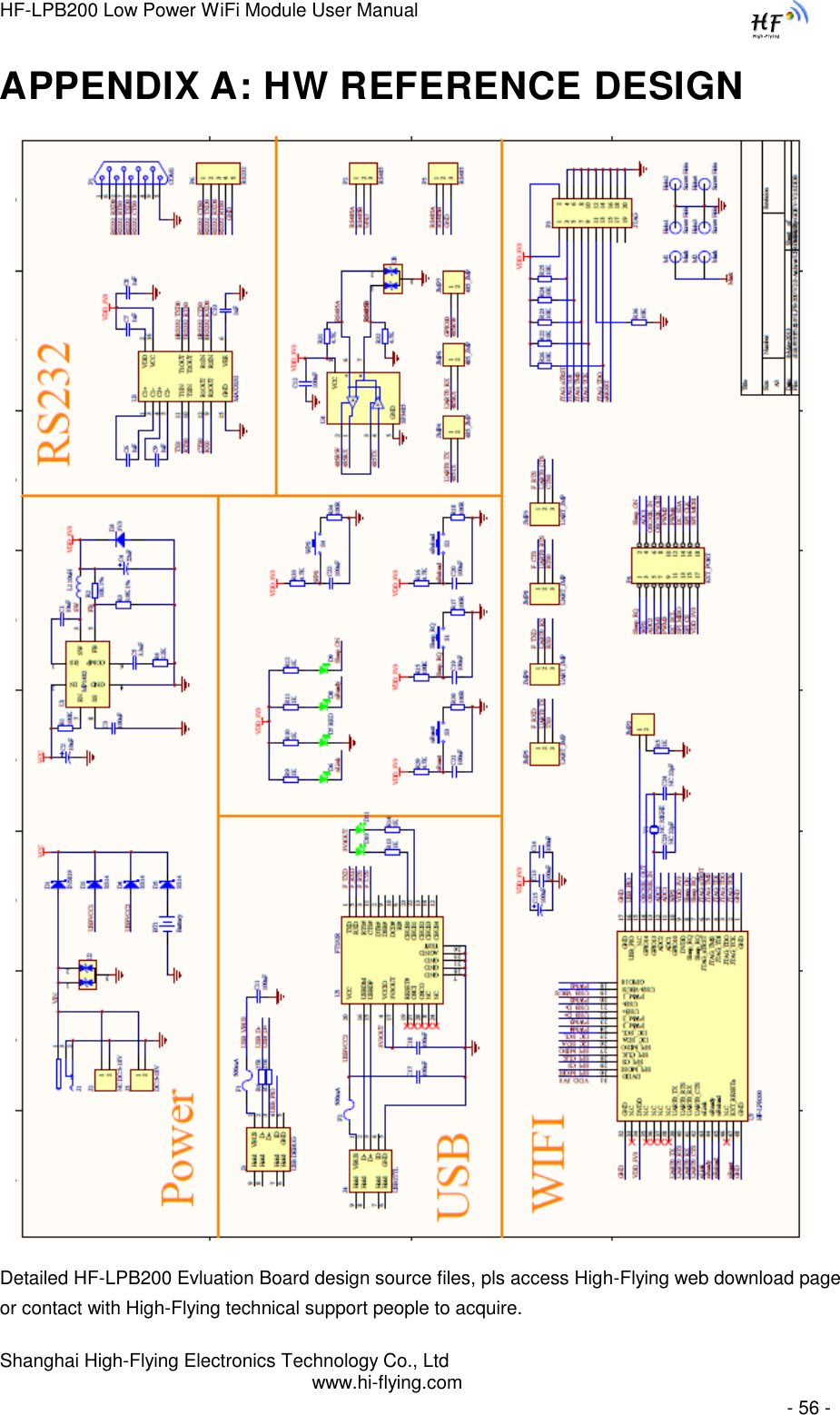
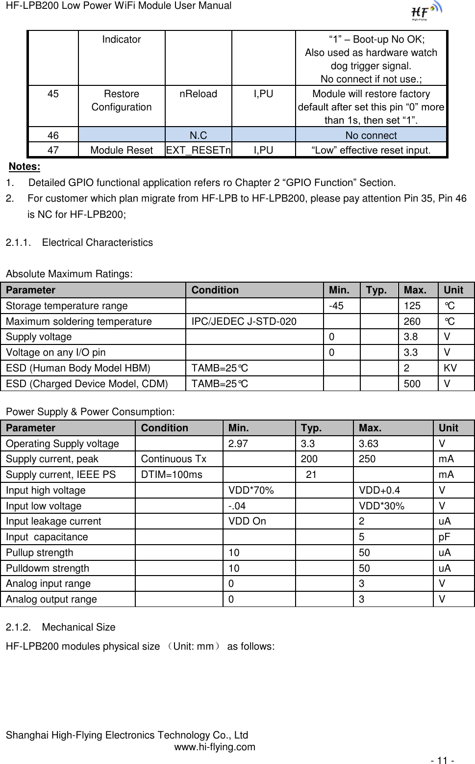
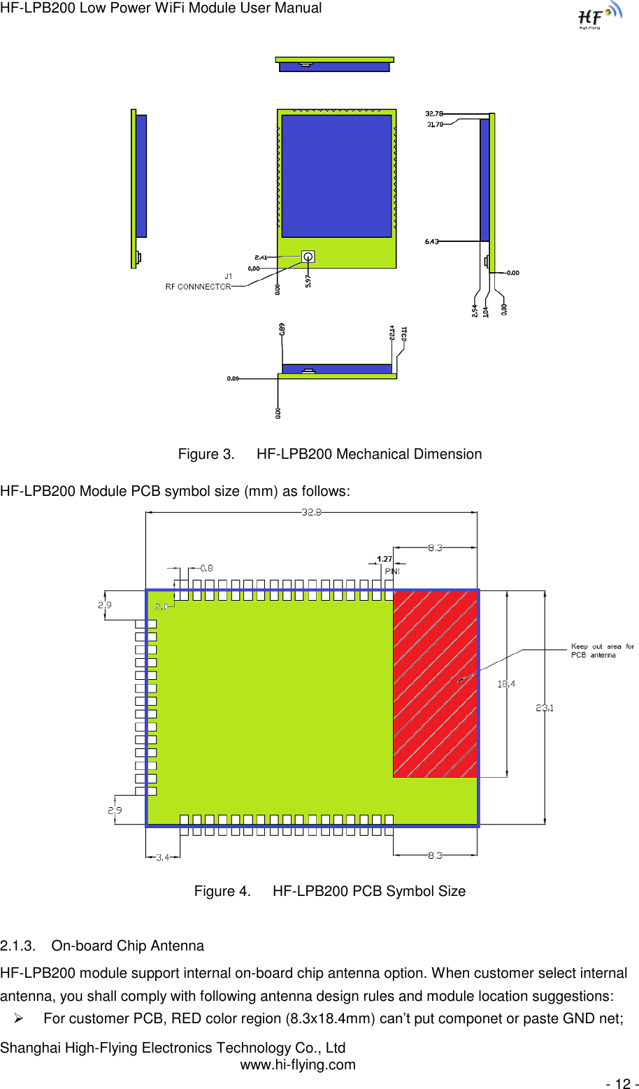
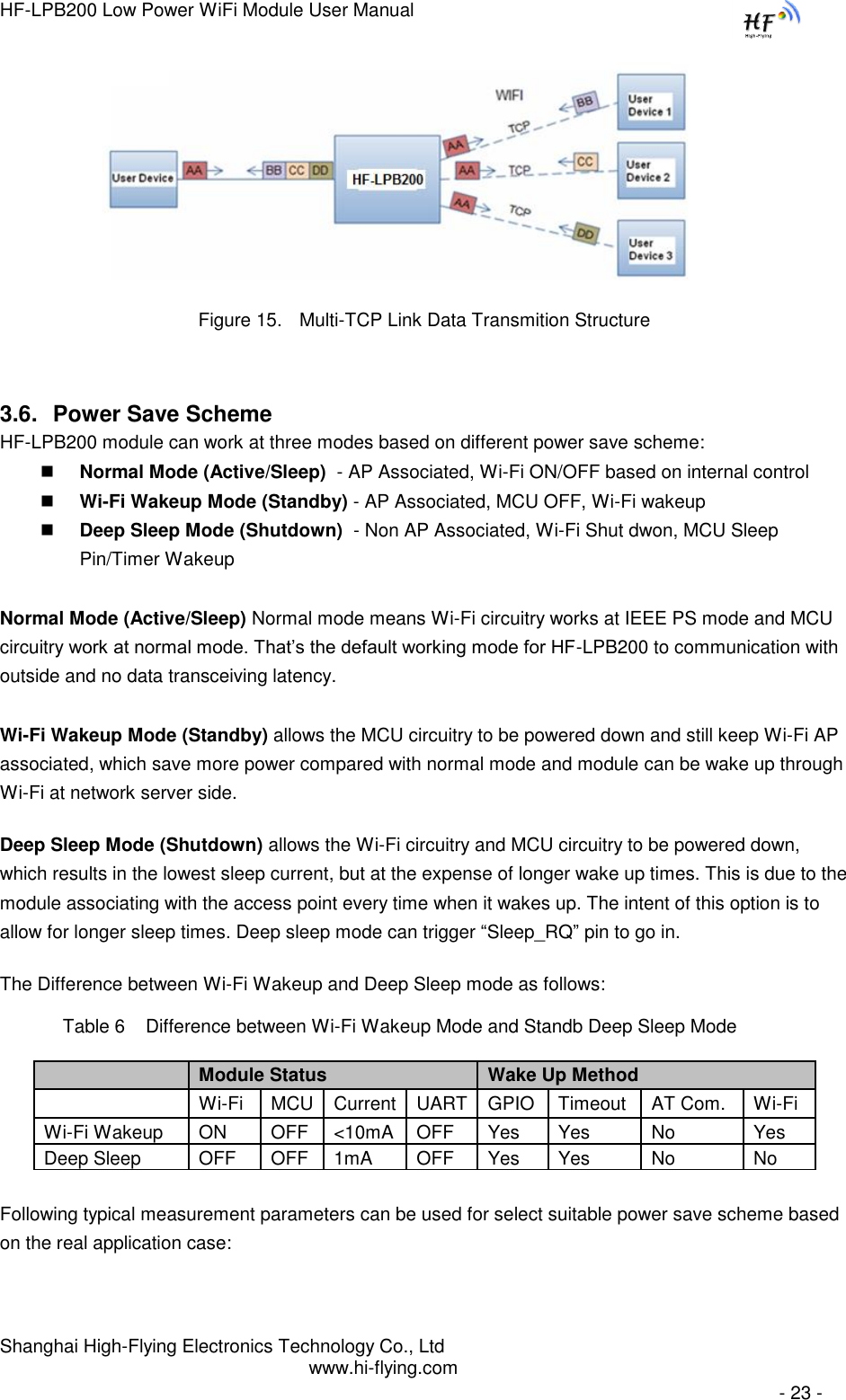
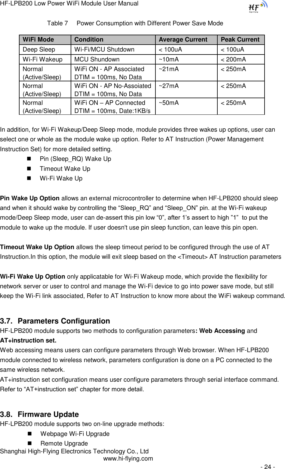
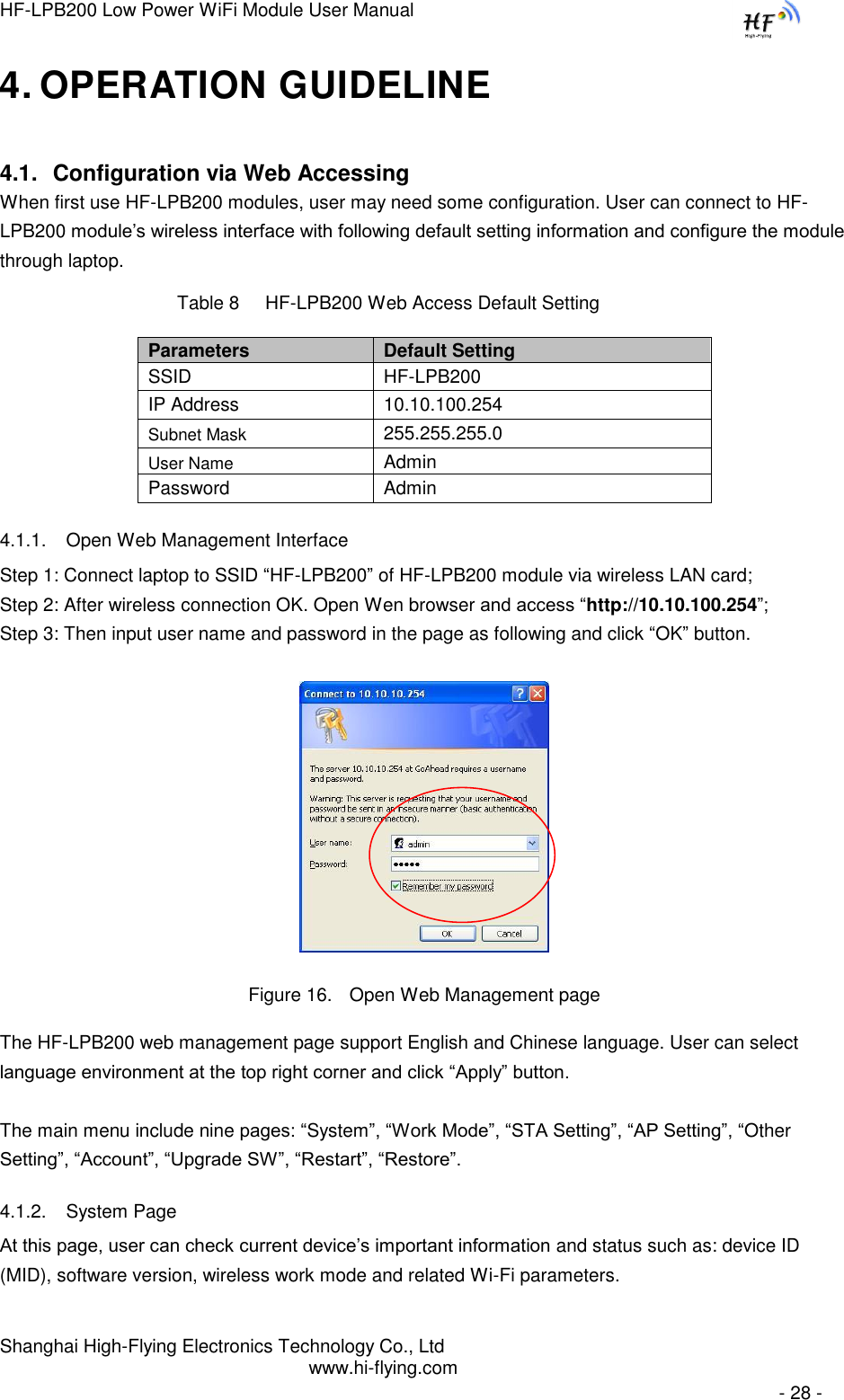
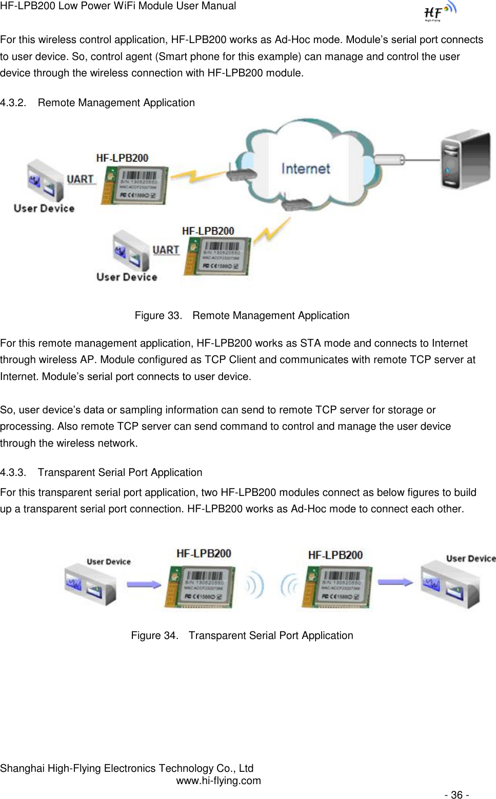
![HF-LPB200 Low Power WiFi Module User Manual Shanghai High-Flying Electronics Technology Co., Ltd www.hi-flying.com - 8 - 1.1.2 Device Paremeters Table 1 HF-LPB200 Module Technical Specifications Class Item Parameters Wireless Parameters Certification FCC/CE Wireless standard 802.11 b/g/n Frequency range 2.412GHz-2.484GHz Transmit Power 802.11b: +16 +/-2dBm (@11Mbps) 802.11g: +14 +/-2dBm (@54Mbps) 802.11n: +13 +/-2dBm (@HT20, MCS7) 802.11n: +12 +/-2dBm (@HT40, MCS7) Receiver Sensitivity 802.11b: -93 dBm (@11Mbps ,CCK) 802.11g: -85 dBm (@54Mbps, OFDM) 802.11n: -82 dBm (@HT20, MCS7) Internal:On-board PCB antenna Hardware Parameters Data Interface UART SPI, PWM, GPIO… Others: USB, ADC, RTC… Operating Voltage 3.1~3.6V Operating Current Peak [Continuous TX]: ~240mA Normal [WiFi ON/OFF, DTIM=100ms]: AP Associate: ~21mA; No-AP Associate:~26mA Wakeup-on-Wireless Mode: ~10mA; Deep Sleep: <100uA Operating Temp. 0℃- 70℃ Storage Temp. -45℃- 125℃ Dimensions and Size 23.1mm×32.8mm×2.7mm Software Parameters Network Type STA /AP/STA+AP/Wi-Fi Direct Security Mechanisms WEP/WPA-PSK/WPA2-PSK Encryption WEP64/WEP128/TKIP/AES Update Firmware Local Wireless (OTA), Remote Customization Web Page Upgrade Provide SDK for application develop Reserved Resource Flash: >200KB; SRAM:>100KB Network Protocol IPv4,TCP/UDP/FTP/HTTP, FTTPS,TLS,mDNS User Configuration AT+instruction set, Web page/ Android/ iOS Smart Link APP tools 1.1.3 Key Application Remote equipment monitoring Smart Home/Energy Industrial sensors and controls Home automation Medical/Healthcare devices](https://usermanual.wiki/High-Flying-Electronics-Technology/HF-LPB200.Manual/User-Guide-2133759-Page-8.png)
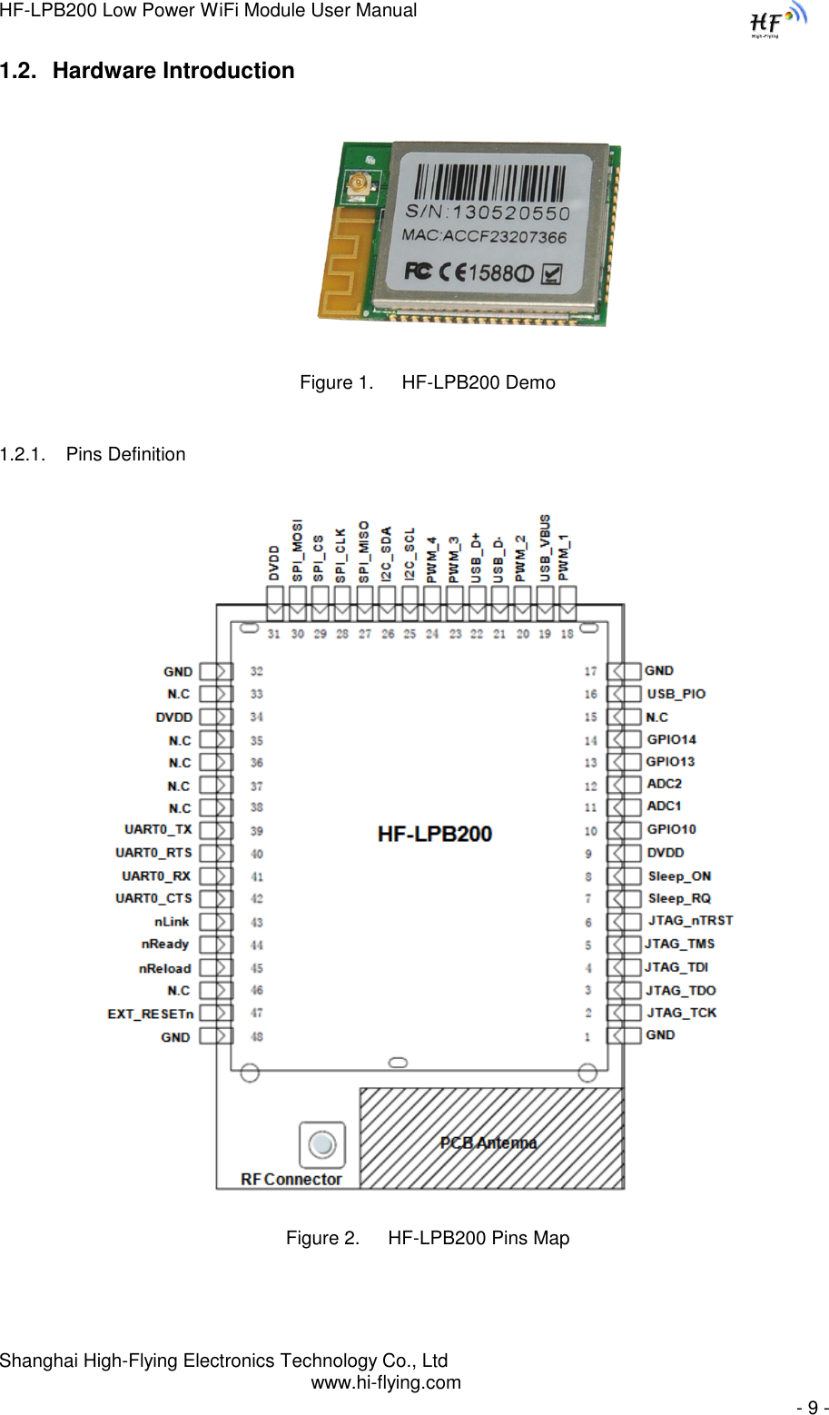
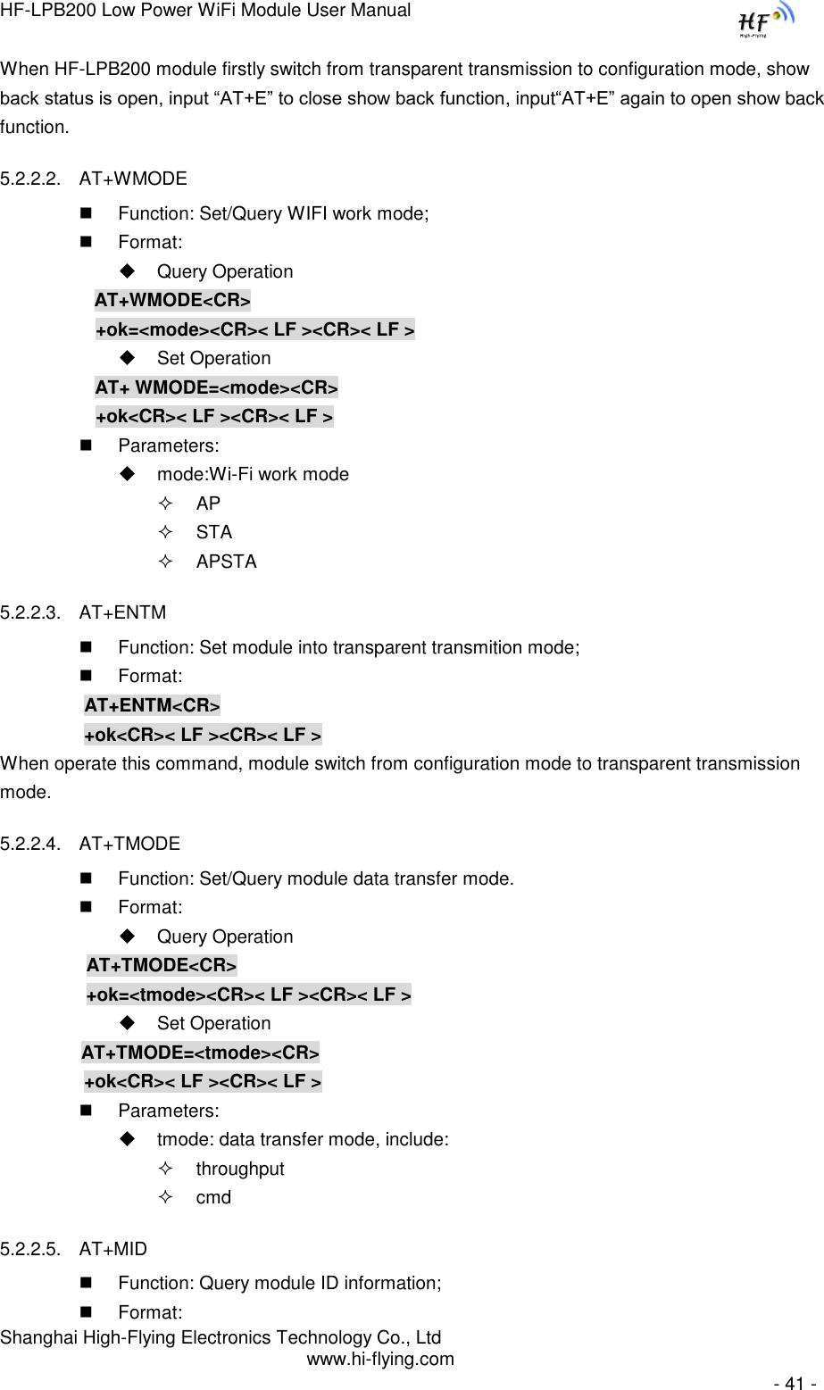
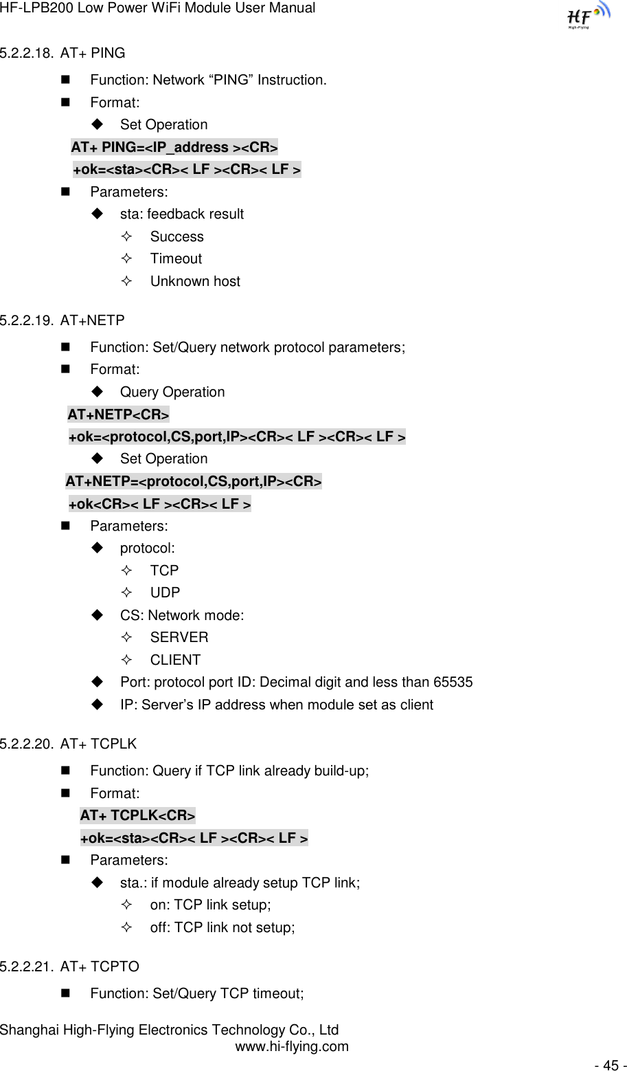
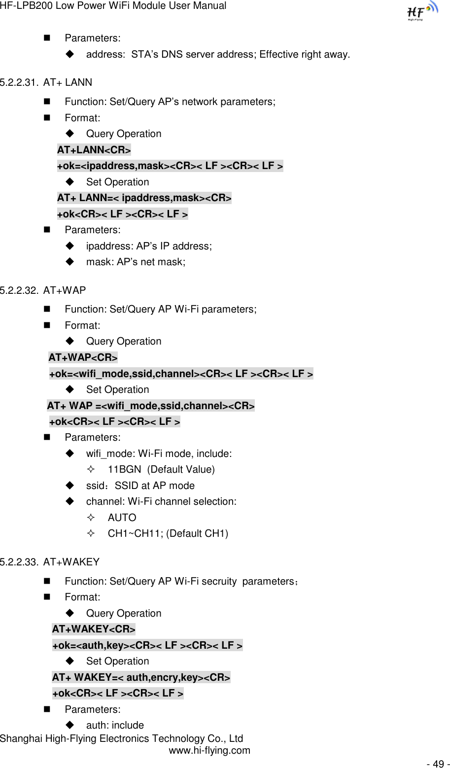
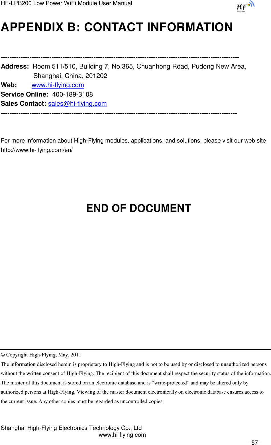
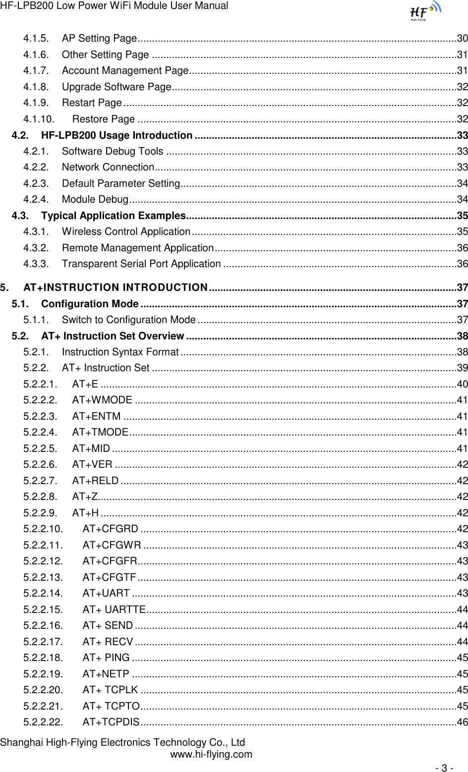
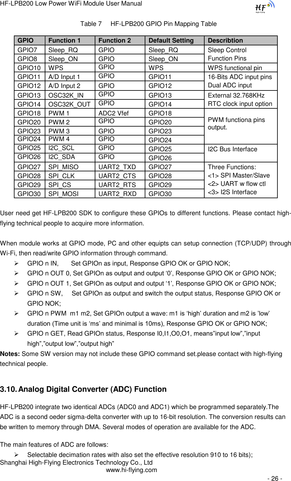
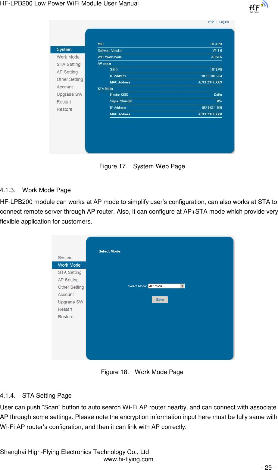
![HF-LPB200 Low Power WiFi Module User Manual Shanghai High-Flying Electronics Technology Co., Ltd www.hi-flying.com - 25 - Webpaged based Wi-Fi upgrade, please refer to 3.1.8 firmware upgrade page, user can upload firmware file from PC to HF-LPB200. HF-LPB200 module also support upgrade from remote HTTP server, keep module connects to AP router before excuate remote HTTP upgrade. Remote upgrade have two methods: Direct Download and Upgrade, Configure File Based Upgrade. Configure File Based Upgrade AT+UPURL command to set the remote directory which the configuration file located, such as AT+UPURL=http://www.hi-flying.com/!admin/down/ Notes: The last ‟/‟ can‟t be remove AT+UPFILE command to set the configuration file name, such as AT+UPFILE=config.txt AT+UPST command to start remote upgrade. After excuate this command, the module will firstly download configuration file (“config.txt”), then download the upgrade file base on the URL address listed in the configure file. General “config.txt” file format as following example: [URL]=”http://www.hi-flying.com/!admin/down/20133181764087523.zip” Direct Download and Upgrade AT+UPURL command to set the remote directory and file name, such as: AT+UPURL=http://www.hi-flying.com/!admin/down/,lpb.bin After excuate this command, the module will directly download the “lpb.bin” file from remote directory and start upgrade. Notes: please contact with high-flying technical people before upgrade firmware, or maybe damage the module and can‟t work again. 3.9. GPIO Function HF-LPB200 module can provide maximum 17 GPIO pins, which include following configurable interface application: Two A/D analog input pins, dual channel, 16-bit ADC with sample rate upto 250KHz; Four PWM ouput pins (4 channel); 32.768KHz Crystal input for RTC function support; Two Pin sleep control pins for low power application; One WPS functional pin; One I2C interace; One General Serial Communication Port, which can configured as Master/Slave SPI Interface; UART2 Interface with flow control; I2S audio interface; HF-LPB200 GPIO pin map as following table:](https://usermanual.wiki/High-Flying-Electronics-Technology/HF-LPB200.Manual/User-Guide-2133759-Page-25.png)
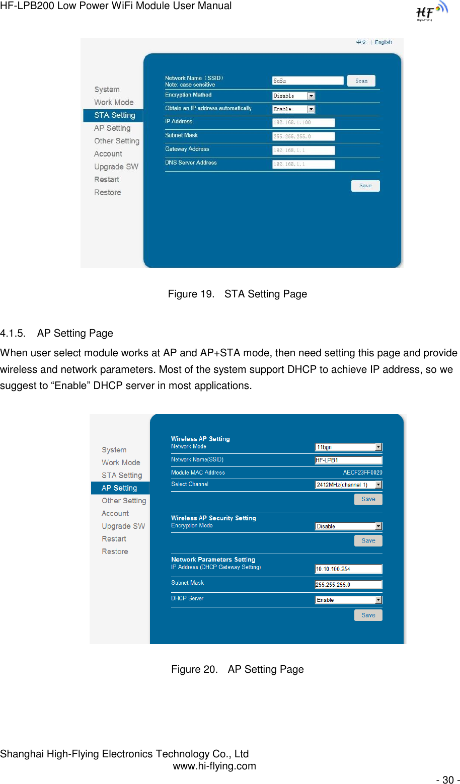
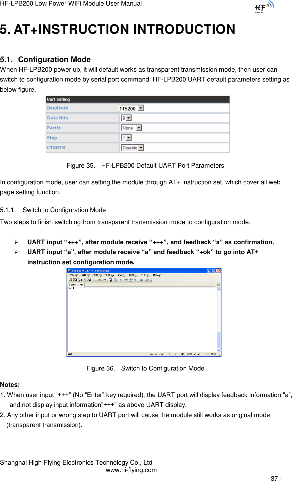
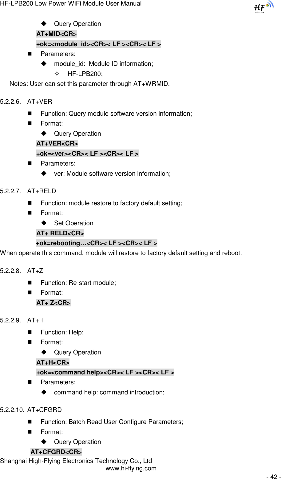
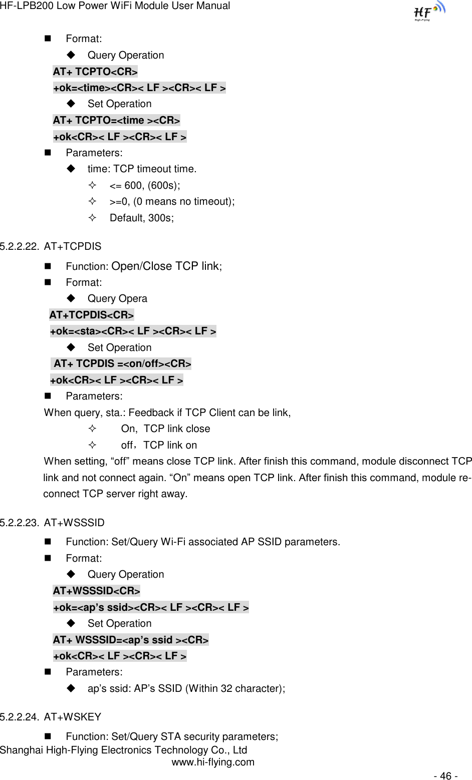
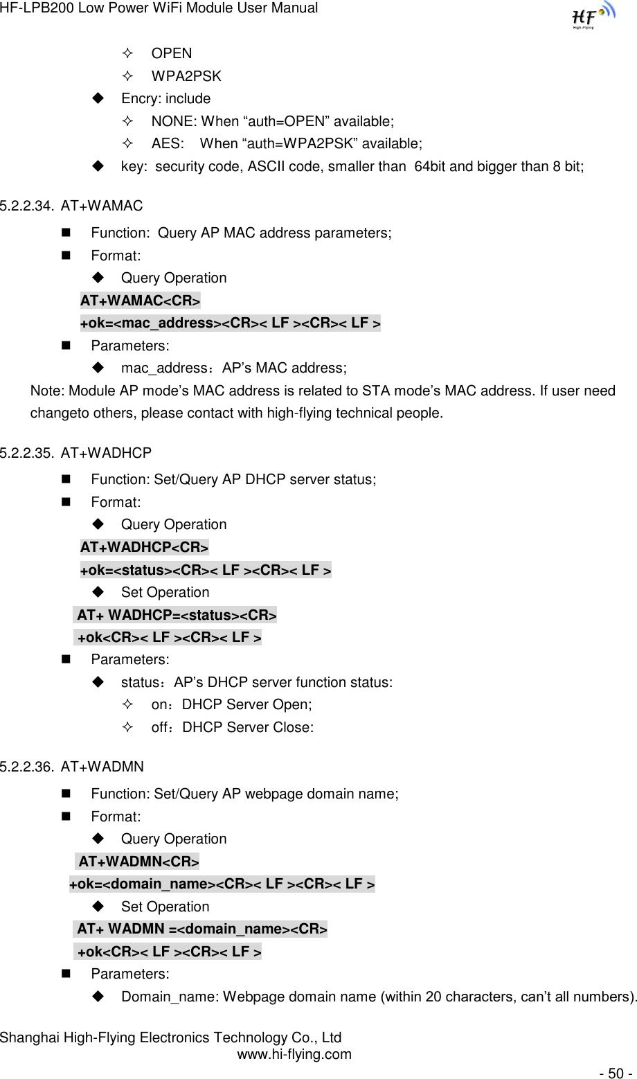
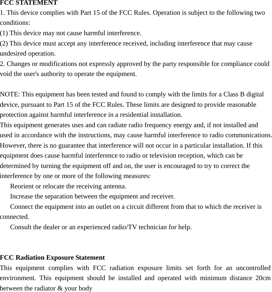
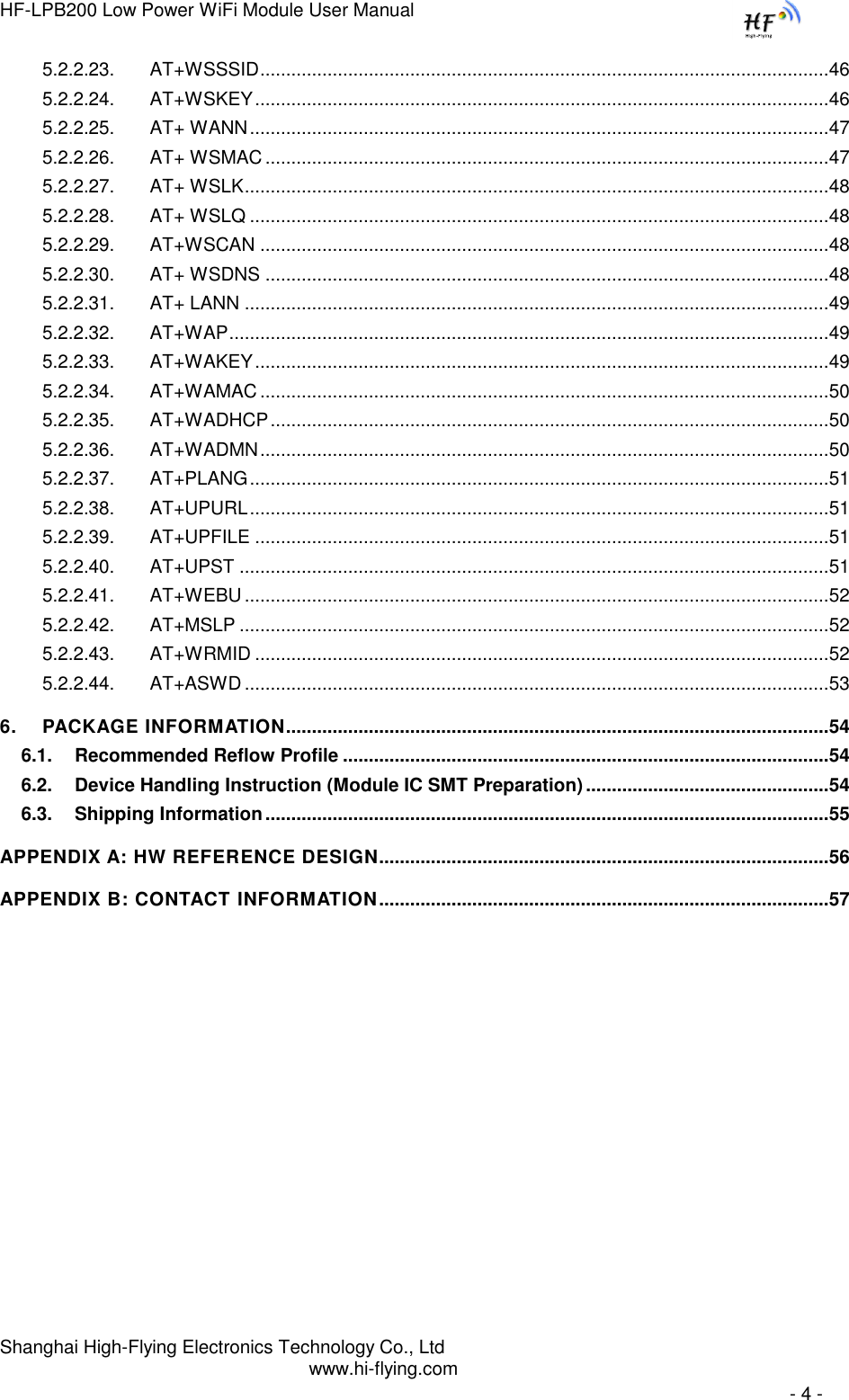
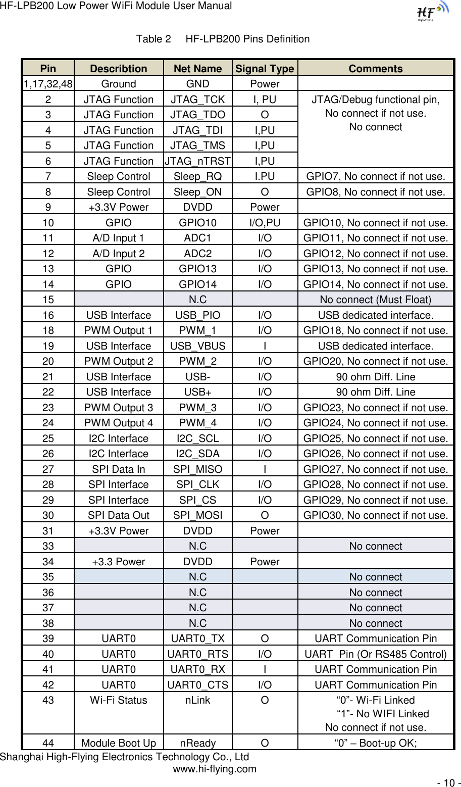
![HF-LPB200 Low Power WiFi Module User Manual Shanghai High-Flying Electronics Technology Co., Ltd www.hi-flying.com - 38 - 5.2. AT+ Instruction Set Overview User can input AT+ Instruction through hyper terminal or other serial debug terminal, also can program the AT+ Instruction to script. User can also input “AT+H” to list all AT+ Instruction and description to start. Figure 37. ”AT+H” Instruction for Help 5.2.1. Instruction Syntax Format AT+Instruction protocol is based on the instruction of ASCII command style, the description of syntax format as follow. Format Description < >: Means the parts must be included [ ]: Means the optional part Command Message AT+<CMD>[op][para-1,para-2,para-3,para-4…]<CR> AT+: Prefix of command message; CMD: Command string; [op]: Symbol of command operator, “=” : The command requires parameters input; “NULL”: Query the current command parameters setting; [para-n]: Parameters input for setting if required; <CR>:”Enter” Key, it‟s 0x0a or 0x0d in ASCII;](https://usermanual.wiki/High-Flying-Electronics-Technology/HF-LPB200.Manual/User-Guide-2133759-Page-38.png)
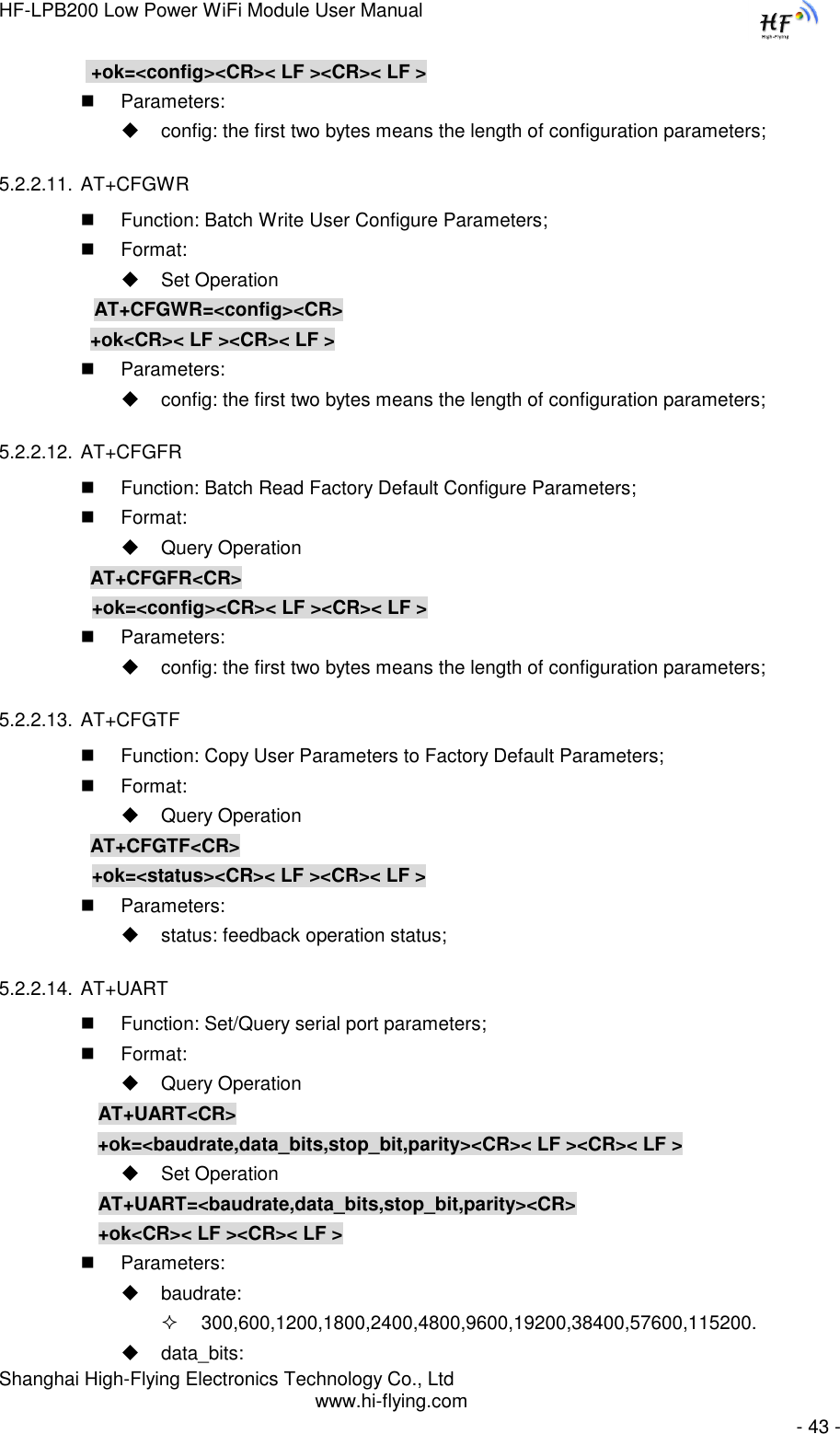
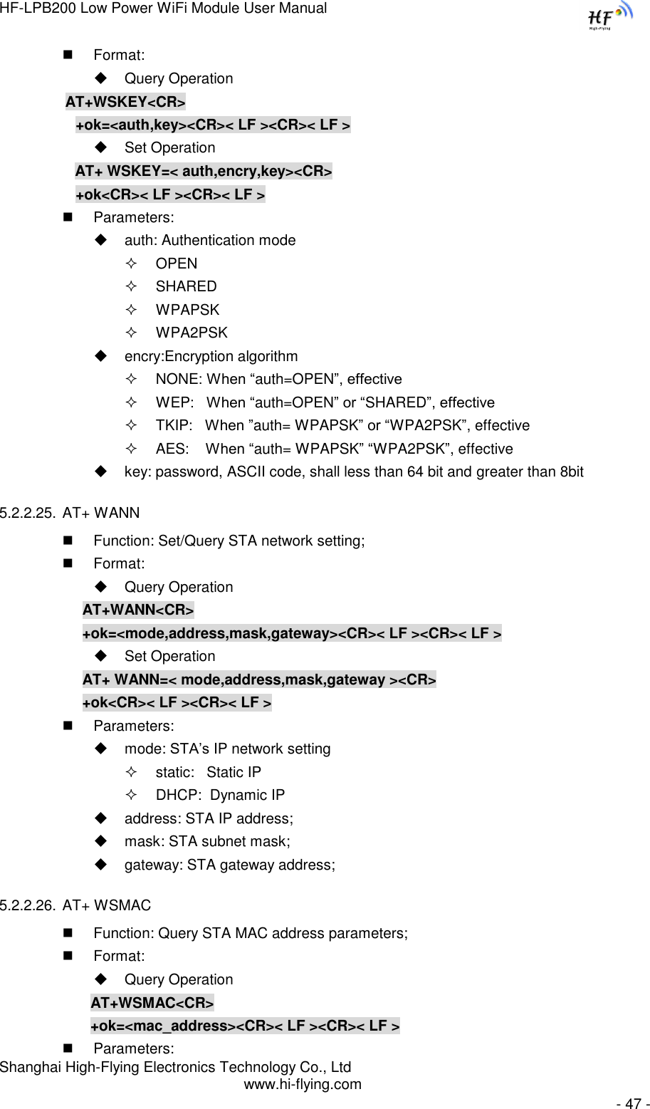
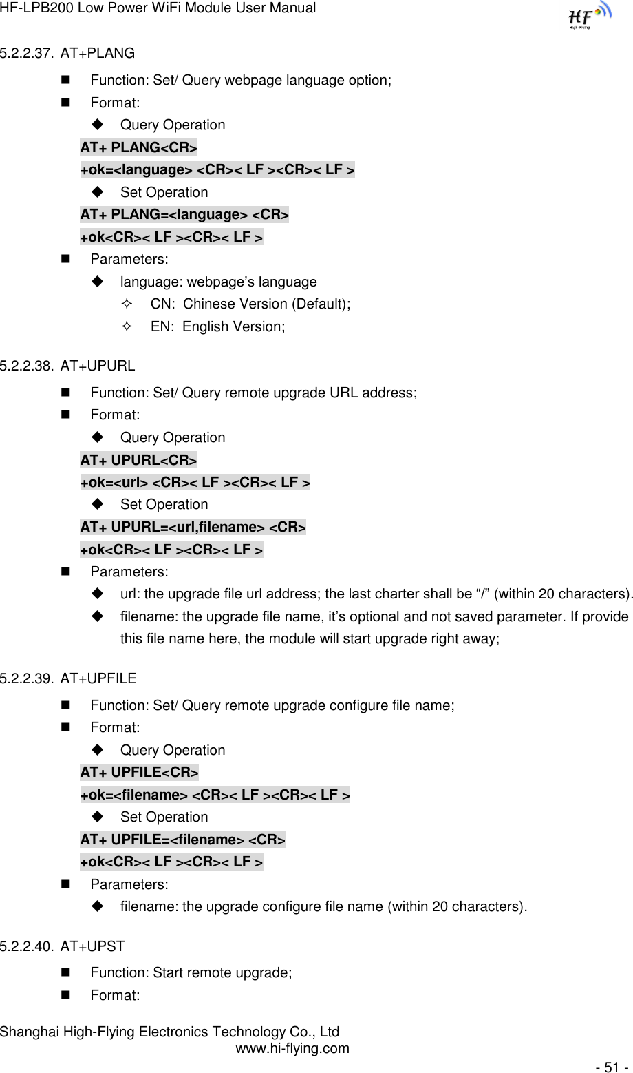
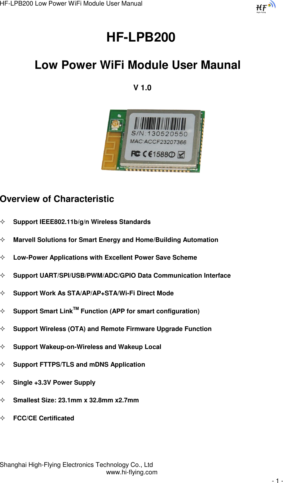
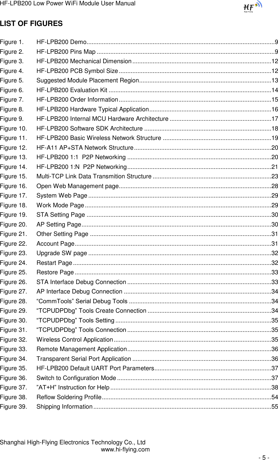
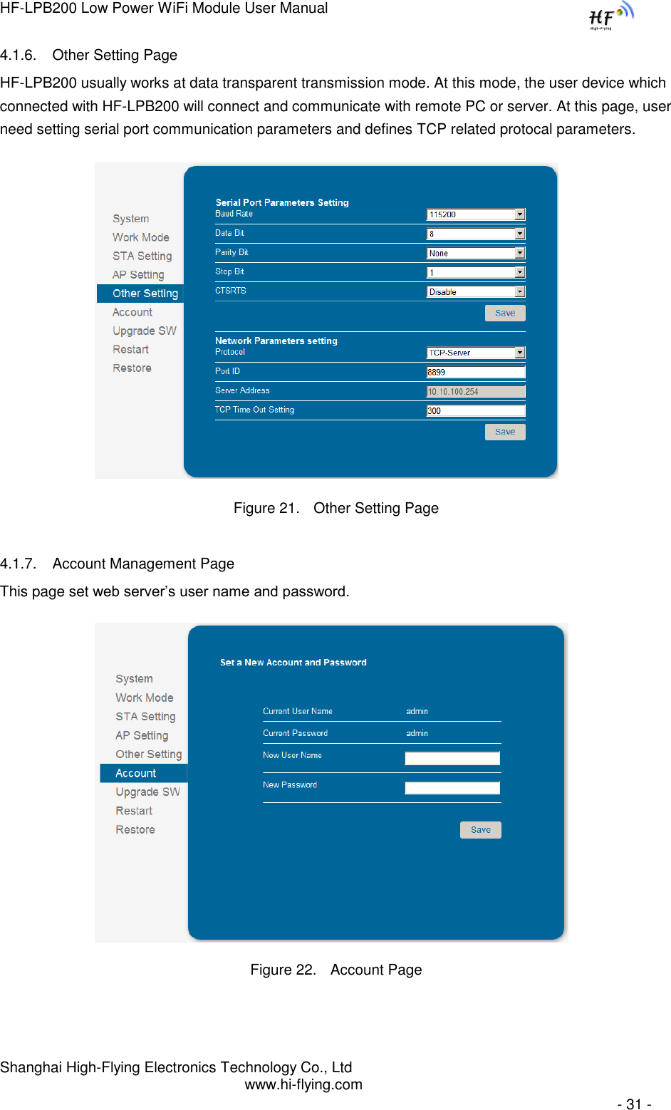
![HF-LPB200 Low Power WiFi Module User Manual Shanghai High-Flying Electronics Technology Co., Ltd www.hi-flying.com - 39 - Notes: When input AT+Instruction, “AT+<CMD>” character will display capital letter automatic and other parts will not change as you input. Response Message +<RSP>[op] [para-1,para-2,para-3,para-4…]<CR><LF><CR><LF> +: Prefix of response message; RSP: Response string; “ok” : Success “ERR”: Failure [op] : = [para-n]: Parameters if query command or Error code when error happened; <CR>: ASCII 0x0d; <LF>: ASCIII 0x0a; Error Code Table 9 Error Code Describtion Error Code Description -1 Invalid Command Format -2 Invalid Command -3 Invalid Operation Symbol -4 Invalid Parameter -5 Operation Not Permitted 5.2.2. AT+ Instruction Set Table 10 AT+ Instruction Set List Instruction Description <null> NULL Managment Instruction Set E Open/Close show back function WMODE Set/Query Wi-Fi work mode (AP/STA/APSTA) ENTM Set module into transparent transition mode TMODE Set/Query module data transfer mode MID Query module ID information VER Query module software version information RELD Restore to factory default setting Z Re-start module H Help Configure Parameters Instruction Set CFGRD Batch Read User Configure Parameters CFGWR Batch Write Configure Parameters CFGFR Batch Read Factory Default Configure Parameters CFGTF Copy User Parameters to Factory Default Parameters](https://usermanual.wiki/High-Flying-Electronics-Technology/HF-LPB200.Manual/User-Guide-2133759-Page-39.png)