High Flying Electronics Technology HF-LPB200 WiFi Module User Manual GPON SFU System Design
High-Flying Electronics Technology Co.,Ltd WiFi Module GPON SFU System Design
Contents
- 1. Manual
- 2. Addendum
Manual
HF-LPB200 Low Power WiFi Module User Manual
Shanghai High-Flying Electronics Technology Co., Ltd
www.hi-flying.com
- 1 -
HF-LPB200
Low Power WiFi Module User Maunal
V 1.0
Overview of Characteristic
Support IEEE802.11b/g/n Wireless Standards
Marvell Solutions for Smart Energy and Home/Building Automation
Low-Power Applications with Excellent Power Save Scheme
Support UART/SPI/USB/PWM/ADC/GPIO Data Communication Interface
Support Work As STA/AP/AP+STA/Wi-Fi Direct Mode
Support Smart LinkTM Function (APP for smart configuration)
Support Wireless (OTA) and Remote Firmware Upgrade Function
Support Wakeup-on-Wireless and Wakeup Local
Support FTTPS/TLS and mDNS Application
Single +3.3V Power Supply
Smallest Size: 23.1mm x 32.8mm x2.7mm
FCC/CE Certificated

HF-LPB200 Low Power WiFi Module User Manual
Shanghai High-Flying Electronics Technology Co., Ltd
www.hi-flying.com
- 2 -
TABLE OF CONTENTS
LIST OF FIGURES ................................................................................................................................... 5
LIST OF TABLES ..................................................................................................................................... 6
HISTORY .................................................................................................................................................. 6
1. PRODUCT OVERVIEW................................................................................................................. 7
1.1. General Description ................................................................................................................. 7
1.1.1 Device Features .................................................................................................................. 7
1.1.2 Device Paremeters ............................................................................................................. 8
1.1.3 Key Application ................................................................................................................... 8
1.2. Hardware Introduction ............................................................................................................. 9
1.2.1. Pins Definition ..................................................................................................................... 9
2.1.1. Electrical Characteristics ................................................................................................... 11
2.1.2. Mechanical Size ................................................................................................................ 11
2.1.3. On-board Chip Antenna .................................................................................................... 12
2.1.4. External Antenna ................................................................................... 错误!未定义书签。
2.1.5. Evaluation Kit .................................................................................................................... 13
2.1.6. Order Information .............................................................................................................. 15
2.2. Typical Application ................................................................................................................ 16
2.2.1. Hardware Typical Application ............................................................................................ 16
2.2.2. Internal MCU Hardware Feature ....................................................................................... 17
2.2.3. Software SDK Architecture ............................................................................................... 18
3. FUNCTIONAL DESCRIPTION ................................................................................................... 19
3.1. Wireless Networking .............................................................................................................. 19
3.1.1. Basic Wireless Network Based On AP (Infrastructure) .................................................... 19
3.1.2. Wireless Network Based On AP+STA .............................................................................. 19
3.1.3. Wi-Fi Direct Network ......................................................................................................... 20
3.2. Work Mode : Transparent Transmission Mode ................................................................... 21
3.3. UART Frame Scheme ............................................................................................................. 22
3.4. Encryption............................................................................................................................... 22
3.5. Multi-TCP Link Connection ................................................................................................... 22
3.6. Power Save Scheme .............................................................................................................. 23
3.7. Parameters Configuration ..................................................................................................... 24
3.8. Firmware Update .................................................................................................................... 24
3.9. GPIO Function ........................................................................................................................ 25
3.10. Analog Digital Converter (ADC) Function ........................................................................ 26
4. OPERATION GUIDELINE........................................................................................................... 28
4.1. Configuration via Web Accessing ........................................................................................ 28
4.1.1. Open Web Management Interface ................................................................................... 28
4.1.2. System Page ..................................................................................................................... 28
4.1.3. Work Mode Page .............................................................................................................. 29
4.1.4. STA Setting Page ............................................................................................................. 29

HF-LPB200 Low Power WiFi Module User Manual
Shanghai High-Flying Electronics Technology Co., Ltd
www.hi-flying.com
- 3 -
4.1.5. AP Setting Page ................................................................................................................ 30
4.1.6. Other Setting Page ........................................................................................................... 31
4.1.7. Account Management Page .............................................................................................. 31
4.1.8. Upgrade Software Page .................................................................................................... 32
4.1.9. Restart Page ..................................................................................................................... 32
4.1.10. Restore Page ................................................................................................................ 32
4.2. HF-LPB200 Usage Introduction ............................................................................................ 33
4.2.1. Software Debug Tools ...................................................................................................... 33
4.2.2. Network Connection .......................................................................................................... 33
4.2.3. Default Parameter Setting ................................................................................................. 34
4.2.4. Module Debug ................................................................................................................... 34
4.3. Typical Application Examples............................................................................................... 35
4.3.1. Wireless Control Application ............................................................................................. 35
4.3.2. Remote Management Application ..................................................................................... 36
4.3.3. Transparent Serial Port Application .................................................................................. 36
5. AT+INSTRUCTION INTRODUCTION ....................................................................................... 37
5.1. Configuration Mode ............................................................................................................... 37
5.1.1. Switch to Configuration Mode ........................................................................................... 37
5.2. AT+ Instruction Set Overview ............................................................................................... 38
5.2.1. Instruction Syntax Format ................................................................................................. 38
5.2.2. AT+ Instruction Set ........................................................................................................... 39
5.2.2.1. AT+E ............................................................................................................................. 40
5.2.2.2. AT+WMODE ................................................................................................................. 41
5.2.2.3. AT+ENTM ..................................................................................................................... 41
5.2.2.4. AT+TMODE ................................................................................................................... 41
5.2.2.5. AT+MID ......................................................................................................................... 41
5.2.2.6. AT+VER ........................................................................................................................ 42
5.2.2.7. AT+RELD ...................................................................................................................... 42
5.2.2.8. AT+Z.............................................................................................................................. 42
5.2.2.9. AT+H ............................................................................................................................. 42
5.2.2.10. AT+CFGRD ............................................................................................................... 42
5.2.2.11. AT+CFGWR .............................................................................................................. 43
5.2.2.12. AT+CFGFR ................................................................................................................ 43
5.2.2.13. AT+CFGTF ................................................................................................................ 43
5.2.2.14. AT+UART .................................................................................................................. 43
5.2.2.15. AT+ UARTTE ............................................................................................................. 44
5.2.2.16. AT+ SEND ................................................................................................................. 44
5.2.2.17. AT+ RECV ................................................................................................................. 44
5.2.2.18. AT+ PING .................................................................................................................. 45
5.2.2.19. AT+NETP .................................................................................................................. 45
5.2.2.20. AT+ TCPLK ............................................................................................................... 45
5.2.2.21. AT+ TCPTO ............................................................................................................... 45
5.2.2.22. AT+TCPDIS ............................................................................................................... 46

HF-LPB200 Low Power WiFi Module User Manual
Shanghai High-Flying Electronics Technology Co., Ltd
www.hi-flying.com
- 4 -
5.2.2.23. AT+WSSSID .............................................................................................................. 46
5.2.2.24. AT+WSKEY ............................................................................................................... 46
5.2.2.25. AT+ WANN ................................................................................................................ 47
5.2.2.26. AT+ WSMAC ............................................................................................................. 47
5.2.2.27. AT+ WSLK ................................................................................................................. 48
5.2.2.28. AT+ WSLQ ................................................................................................................ 48
5.2.2.29. AT+WSCAN .............................................................................................................. 48
5.2.2.30. AT+ WSDNS ............................................................................................................. 48
5.2.2.31. AT+ LANN ................................................................................................................. 49
5.2.2.32. AT+WAP .................................................................................................................... 49
5.2.2.33. AT+WAKEY ............................................................................................................... 49
5.2.2.34. AT+WAMAC .............................................................................................................. 50
5.2.2.35. AT+WADHCP ............................................................................................................ 50
5.2.2.36. AT+WADMN .............................................................................................................. 50
5.2.2.37. AT+PLANG ................................................................................................................ 51
5.2.2.38. AT+UPURL ................................................................................................................ 51
5.2.2.39. AT+UPFILE ............................................................................................................... 51
5.2.2.40. AT+UPST .................................................................................................................. 51
5.2.2.41. AT+WEBU ................................................................................................................. 52
5.2.2.42. AT+MSLP .................................................................................................................. 52
5.2.2.43. AT+WRMID ............................................................................................................... 52
5.2.2.44. AT+ASWD ................................................................................................................. 53
6. PACKAGE INFORMATION......................................................................................................... 54
6.1. Recommended Reflow Profile .............................................................................................. 54
6.2. Device Handling Instruction (Module IC SMT Preparation) ............................................... 54
6.3. Shipping Information ............................................................................................................. 55
APPENDIX A: HW REFERENCE DESIGN....................................................................................... 56
APPENDIX B: CONTACT INFORMATION ....................................................................................... 57

HF-LPB200 Low Power WiFi Module User Manual
Shanghai High-Flying Electronics Technology Co., Ltd
www.hi-flying.com
- 5 -
LIST OF FIGURES
Figure 1. HF-LPB200 Demo ............................................................................................................... 9
Figure 2. HF-LPB200 Pins Map ......................................................................................................... 9
Figure 3. HF-LPB200 Mechanical Dimension .................................................................................. 12
Figure 4. HF-LPB200 PCB Symbol Size .......................................................................................... 12
Figure 5. Suggested Module Placement Region .............................................................................. 13
Figure 6. HF-LPB200 Evaluation Kit ................................................................................................ 14
Figure 7. HF-LPB200 Order Information .......................................................................................... 15
Figure 8. HF-LPB200 Hardware Typical Application ........................................................................ 16
Figure 9. HF-LPB200 Internal MCU Hardware Architecture ............................................................ 17
Figure 10. HF-LPB200 Software SDK Architecture ........................................................................... 18
Figure 11. HF-LPB200 Basic Wireless Network Structure ................................................................ 19
Figure 12. HF-A11 AP+STA Network Structure ................................................................................. 20
Figure 13. HF-LPB200 1:1 P2P Networking ..................................................................................... 20
Figure 14. HF-LPB200 1:N P2P Networking ..................................................................................... 21
Figure 15. Multi-TCP Link Data Transmition Structure ...................................................................... 23
Figure 16. Open Web Management page .......................................................................................... 28
Figure 17. System Web Page ............................................................................................................ 29
Figure 18. Work Mode Page .............................................................................................................. 29
Figure 19. STA Setting Page ............................................................................................................. 30
Figure 20. AP Setting Page ................................................................................................................ 30
Figure 21. Other Setting Page ........................................................................................................... 31
Figure 22. Account Page .................................................................................................................... 31
Figure 23. Upgrade SW page ............................................................................................................ 32
Figure 24. Restart Page ..................................................................................................................... 32
Figure 25. Restore Page .................................................................................................................... 33
Figure 26. STA Interface Debug Connection ..................................................................................... 33
Figure 27. AP Interface Debug Connection ....................................................................................... 34
Figure 28. “CommTools” Serial Debug Tools .................................................................................... 34
Figure 29. “TCPUDPDbg” Tools Create Connection ......................................................................... 34
Figure 30. “TCPUDPDbg” Tools Setting ............................................................................................ 35
Figure 31. “TCPUDPDbg” Tools Connection ..................................................................................... 35
Figure 32. Wireless Control Application ............................................................................................. 35
Figure 33. Remote Management Application ..................................................................................... 36
Figure 34. Transparent Serial Port Application .................................................................................. 36
Figure 35. HF-LPB200 Default UART Port Parameters ..................................................................... 37
Figure 36. Switch to Configuration Mode ........................................................................................... 37
Figure 37. ”AT+H” Instruction for Help ............................................................................................... 38
Figure 38. Reflow Soldering Profile .................................................................................................... 54
Figure 39. Shipping Information ......................................................................................................... 55

HF-LPB200 Low Power WiFi Module User Manual
Shanghai High-Flying Electronics Technology Co., Ltd
www.hi-flying.com
- 6 -
LIST OF TABLES
Table 1 HF-LPB200 Module Technical Specifications ......................................................................... 8
Table 2 HF-LPB200 Pins Definition .................................................................................................... 10
Table 3 HF-LPB200 External Antenna Parameters ................................................. 错误!未定义书签。
Table 4 HF-LPB200 Evaluation Kit Interface Description ................................................................... 15
Table 6 Difference between Wi-Fi Wakeup Mode and Standb Deep Sleep Mode ............................. 23
Table 7 Power Consumption with Different Power Save Mode .......................................................... 24
Table 7 HF-LPB200 GPIO Pin Mapping Table ................................................................................... 26
Table 8 HF-LPB200 Web Access Default Setting .............................................................................. 28
Table 9 Error Code Describtion .......................................................................................................... 39
Table 10 AT+ Instruction Set List ....................................................................................................... 39
Table 11 Reflow Soldering Parameter .................................................................................................. 54
HISTORY
Ed. V1.0 Created on 5-20-2013.

HF-LPB200 Low Power WiFi Module User Manual
Shanghai High-Flying Electronics Technology Co., Ltd
www.hi-flying.com
- 7 -
1. PRODUCT OVERVIEW
1.1. General Description
The HF-LPB200 is a fully self-contained small form-factor, single stream, 802.11b/g/n Wi-Fi module,
which provide a wireless interface to any equipment with a Serial/SPI/USB/GPIO interface for data
transfer.HF-LPB200 integrate MAC, baseband processor, RF transceiver with power amplifier in
hardware and all Wi-Fi protocol and configuration functionality and networking stack, in embedded
firmware to make a fully self-contained 802.11b/g/n Wi-Fi solution for a variety of applications.
HF-LPB200 support AP+STA wireless networking and support Wi-Fi Direct mode. HF-LPB200 also
provides wireless and remote firmware upgrade, which satisfied all kinds of application requirement.
HF-LPB200 support wakup-on-wireless feature which make it a very suitable solution for battery
applications with excellent power save scheme.
The HF-LPB200 employs the world's lowest power consumption embedded architecture. It has been
optimized for all kinds of client applications in the home automation, smart grid, handheld device,
personal medical application and industrial control that have lower data rates, and transmit or receive
data on an infrequent basis.
The HF-LPB200 integrates all Wi-Fi functionality into a low-profile, 23.1x32.8x 2.7mm SMT module
package that can be easily mounted on main PCB with application specific circuits. Also, module
provides built-in antenna, external antenna option.
1.1.1 Device Features
Single stream Wi-Fi @ 2.4 GHz with support for WEP security mode as well as WPA/WPA2
Fully self-contained serial-to-wireless functionality.
Support IEEE802.11b/g/n Wireless Standards
Ultra-Low-Power for Battery Applications with Excellent Power Save Scheme
Support UART/SPI/USB/PWM/ADC/GPIO Data Communication Interface
Support Work As STA/AP/AP+STA/Wi-Fi Direct Mode
Support Smart LinkTM Function (APP for smart configuration)
Support Wireless (OTA) and Remote Firmware Upgrade Function
Support Wakeup-on-Wireless and Wakeup Local
Support TLS/SSL and mDNS Protocal
Reserve More Than 512KB Flash and 128KB SRAM For User Defined Application
Single +3.3V Power Supply
Smallest Size: 23.1mm x 32.8mm x2.7mm
FCC/CE Certificated

HF-LPB200 Low Power WiFi Module User Manual
Shanghai High-Flying Electronics Technology Co., Ltd
www.hi-flying.com
- 8 -
1.1.2 Device Paremeters
Table 1 HF-LPB200 Module Technical Specifications
Class
Item
Parameters
Wireless
Parameters
Certification
FCC/CE
Wireless standard
802.11 b/g/n
Frequency range
2.412GHz-2.484GHz
Transmit Power
802.11b: +16 +/-2dBm (@11Mbps)
802.11g: +14 +/-2dBm (@54Mbps)
802.11n: +13 +/-2dBm (@HT20, MCS7)
802.11n: +12 +/-2dBm (@HT40, MCS7)
Receiver Sensitivity
802.11b: -93 dBm (@11Mbps ,CCK)
802.11g: -85 dBm (@54Mbps, OFDM)
802.11n: -82 dBm (@HT20, MCS7)
Internal:On-board PCB antenna
Hardware
Parameters
Data Interface
UART
SPI, PWM, GPIO…
Others: USB, ADC, RTC…
Operating Voltage
3.1~3.6V
Operating Current
Peak [Continuous TX]: ~240mA
Normal [WiFi ON/OFF, DTIM=100ms]:
AP Associate: ~21mA; No-AP Associate:~26mA
Wakeup-on-Wireless Mode: ~10mA;
Deep Sleep: <100uA
Operating Temp.
0℃- 70℃
Storage Temp.
-45℃- 125℃
Dimensions and Size
23.1mm×32.8mm×2.7mm
Software
Parameters
Network Type
STA /AP/STA+AP/Wi-Fi Direct
Security Mechanisms
WEP/WPA-PSK/WPA2-PSK
Encryption
WEP64/WEP128/TKIP/AES
Update Firmware
Local Wireless (OTA), Remote
Customization
Web Page Upgrade
Provide SDK for application develop
Reserved Resource
Flash: >200KB; SRAM:>100KB
Network Protocol
IPv4,TCP/UDP/FTP/HTTP, FTTPS,TLS,mDNS
User Configuration
AT+instruction set, Web page/ Android/ iOS
Smart Link APP tools
1.1.3 Key Application
Remote equipment monitoring
Smart Home/Energy
Industrial sensors and controls
Home automation
Medical/Healthcare devices
HF-LPB200 Low Power WiFi Module User Manual
Shanghai High-Flying Electronics Technology Co., Ltd
www.hi-flying.com
- 9 -
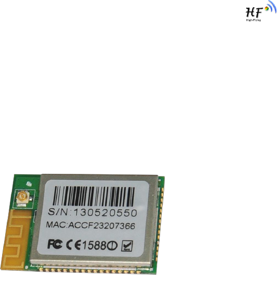
1.2. Hardware Introduction
Figure 1. HF-LPB200 Demo
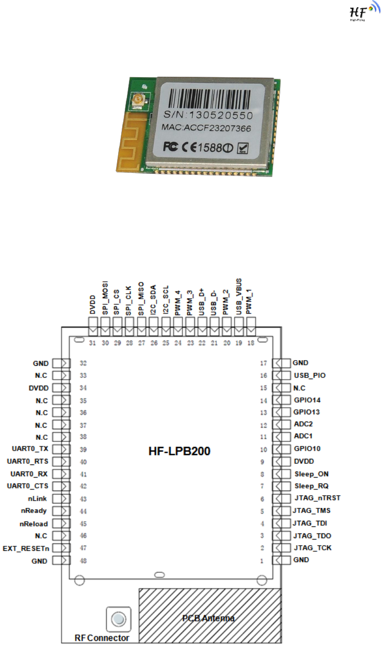
1.2.1. Pins Definition
Figure 2. HF-LPB200 Pins Map

HF-LPB200 Low Power WiFi Module User Manual
Shanghai High-Flying Electronics Technology Co., Ltd
www.hi-flying.com
- 10 -
Table 2 HF-LPB200 Pins Definition
Pin
Describtion
Net Name
Signal Type
Comments
1,17,32,48
Ground
GND
Power
2
JTAG Function
JTAG_TCK
I, PU
JTAG/Debug functional pin,
No connect if not use.
No connect
3
JTAG Function
JTAG_TDO
O
4
JTAG Function
JTAG_TDI
I,PU
5
JTAG Function
JTAG_TMS
I,PU
6
JTAG Function
JTAG_nTRST
I,PU
7
Sleep Control
Sleep_RQ
I.PU
GPIO7, No connect if not use.
8
Sleep Control
Sleep_ON
O
GPIO8, No connect if not use.
9
+3.3V Power
DVDD
Power
10
GPIO
GPIO10
I/O,PU
GPIO10, No connect if not use.
11
A/D Input 1
ADC1
I/O
GPIO11, No connect if not use.
12
A/D Input 2
ADC2
I/O
GPIO12, No connect if not use.
13
GPIO
GPIO13
I/O
GPIO13, No connect if not use.
14
GPIO
GPIO14
I/O
GPIO14, No connect if not use.
15
N.C
No connect (Must Float)
16
USB Interface
USB_PIO
I/O
USB dedicated interface.
18
PWM Output 1
PWM_1
I/O
GPIO18, No connect if not use.
19
USB Interface
USB_VBUS
I
USB dedicated interface.
20
PWM Output 2
PWM_2
I/O
GPIO20, No connect if not use.
21
USB Interface
USB-
I/O
90 ohm Diff. Line
22
USB Interface
USB+
I/O
90 ohm Diff. Line
23
PWM Output 3
PWM_3
I/O
GPIO23, No connect if not use.
24
PWM Output 4
PWM_4
I/O
GPIO24, No connect if not use.
25
I2C Interface
I2C_SCL
I/O
GPIO25, No connect if not use.
26
I2C Interface
I2C_SDA
I/O
GPIO26, No connect if not use.
27
SPI Data In
SPI_MISO
I
GPIO27, No connect if not use.
28
SPI Interface
SPI_CLK
I/O
GPIO28, No connect if not use.
29
SPI Interface
SPI_CS
I/O
GPIO29, No connect if not use.
30
SPI Data Out
SPI_MOSI
O
GPIO30, No connect if not use.
31
+3.3V Power
DVDD
Power
33
N.C
No connect
34
+3.3 Power
DVDD
Power
35
N.C
No connect
36
N.C
No connect
37
N.C
No connect
38
N.C
No connect
39
UART0
UART0_TX
O
UART Communication Pin
40
UART0
UART0_RTS
I/O
UART Pin (Or RS485 Control)
41
UART0
UART0_RX
I
UART Communication Pin
42
UART0
UART0_CTS
I/O
UART Communication Pin
43
Wi-Fi Status
nLink
O
“0”- Wi-Fi Linked
“1”- No WIFI Linked
No connect if not use.
44
Module Boot Up
nReady
O
“0” – Boot-up OK;
HF-LPB200 Low Power WiFi Module User Manual
Shanghai High-Flying Electronics Technology Co., Ltd
www.hi-flying.com
- 11 -
Indicator
“1” – Boot-up No OK;
Also used as hardware watch
dog trigger signal.
No connect if not use.;
45
Restore
Configuration
nReload
I,PU
Module will restore factory
default after set this pin “0” more
than 1s, then set “1”.
46
N.C
No connect
47
Module Reset
EXT_RESETn
I,PU
“Low” effective reset input.
Notes:
1. Detailed GPIO functional application refers ro Chapter 2 “GPIO Function” Section.
2. For customer which plan migrate from HF-LPB to HF-LPB200, please pay attention Pin 35, Pin 46
is NC for HF-LPB200;
2.1.1. Electrical Characteristics
Absolute Maximum Ratings:
Parameter
Condition
Min.
Typ.
Max.
Unit
Storage temperature range
-45
125
°C
Maximum soldering temperature
IPC/JEDEC J-STD-020
260
°C
Supply voltage
0
3.8
V
Voltage on any I/O pin
0
3.3
V
ESD (Human Body Model HBM)
TAMB=25°C
2
KV
ESD (Charged Device Model, CDM)
TAMB=25°C
500
V
Power Supply & Power Consumption:
Parameter
Condition
Min.
Typ.
Max.
Unit
Operating Supply voltage
2.97
3.3
3.63
V
Supply current, peak
Continuous Tx
200
250
mA
Supply current, IEEE PS
DTIM=100ms
21
mA
Input high voltage
VDD*70%
VDD+0.4
V
Input low voltage
-.04
VDD*30%
V
Input leakage current
VDD On
2
uA
Input capacitance
5
pF
Pullup strength
10
50
uA
Pulldowm strength
10
50
uA
Analog input range
0
3
V
Analog output range
0
3
V
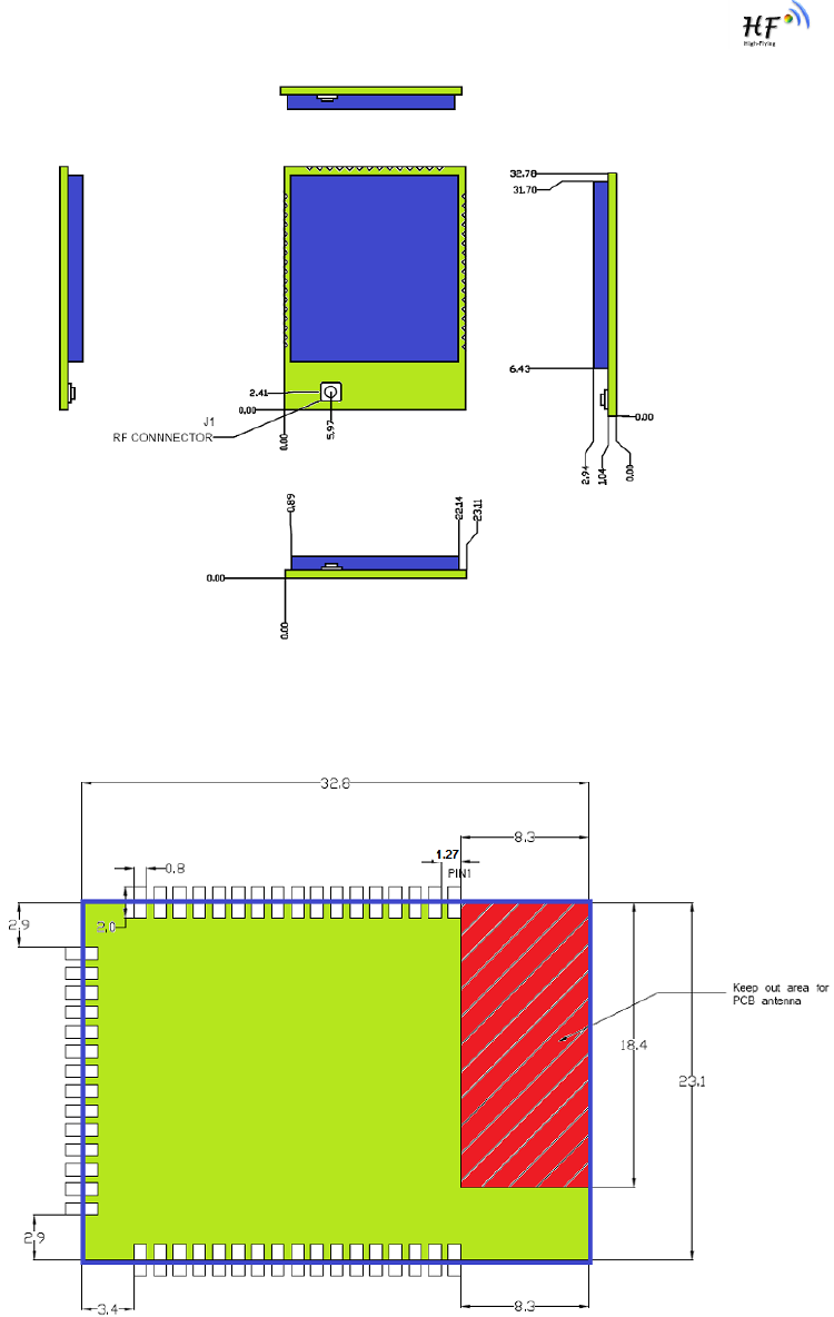
2.1.2. Mechanical Size
HF-LPB200 modules physical size (Unit: mm) as follows:
HF-LPB200 Low Power WiFi Module User Manual
Shanghai High-Flying Electronics Technology Co., Ltd
www.hi-flying.com
- 12 -
Figure 3. HF-LPB200 Mechanical Dimension
HF-LPB200 Module PCB symbol size (mm) as follows:
Figure 4. HF-LPB200 PCB Symbol Size
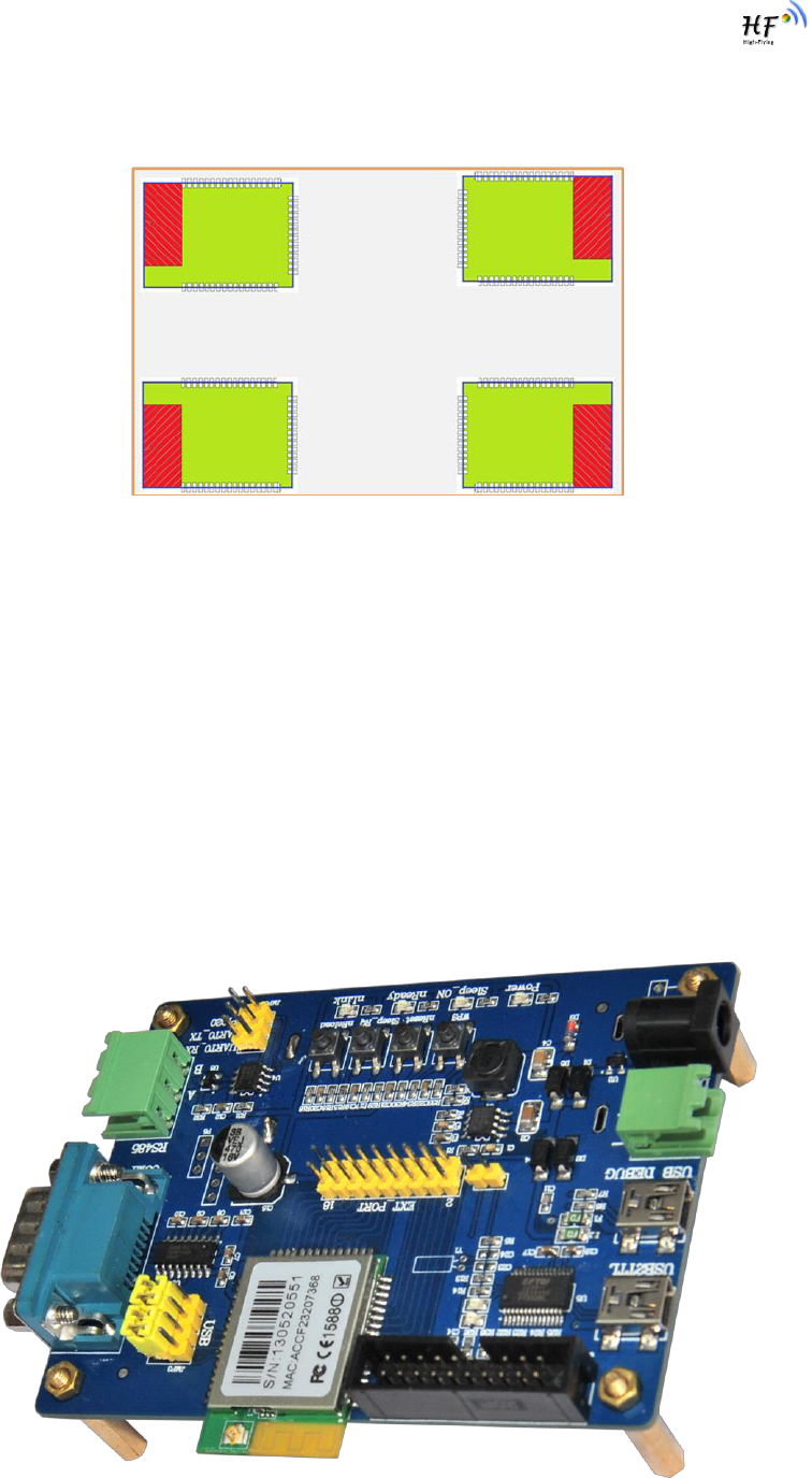
2.1.3. On-board Chip Antenna
HF-LPB200 module support internal on-board chip antenna option. When customer select internal
antenna, you shall comply with following antenna design rules and module location suggestions:
For customer PCB, RED color region (8.3x18.4mm) can‟t put componet or paste GND net;
HF-LPB200 Low Power WiFi Module User Manual
Shanghai High-Flying Electronics Technology Co., Ltd
www.hi-flying.com
- 13 -
Antenna must away from metal or high components at least 10mm;
Antenna can‟t be shieldedby any meal enclosure; All cover, include plastic, shall away from
antenna at least 10mm;
Figure 5. Suggested Module Placement Region
High-Flying suggest HF-LPB200 module better locate in following region at customer board, which to
reduce the effect to antenna and wireless signal, and better consult High-Flying technical people when
you structure your module placement and PCB layout.
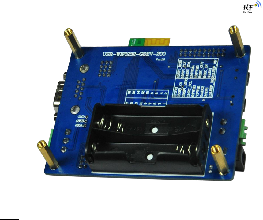
2.1.4. Evaluation Kit
High-Flying provides the evaluation kit to promote user to familiar the product and develop the detailed
application. The evaluation kit shown as below, user can connect to HF-LPB200 module with the RS-
232 UART, RS485, USB (Internal UART-USB convetor) or Wireless port to configure the parameters,
manage the module or do some functional tests.
Detailed EVK applicarion pls refer to HF-LPB200 SDK user guide.
HF-LPB200 Low Power WiFi Module User Manual
Shanghai High-Flying Electronics Technology Co., Ltd
www.hi-flying.com
- 14 -
Figure 6. HF-LPB200 Evaluation Kit
Notes: User may needs download USB - UART port driver from High-Flying web or contact with
technical support people for more detail.
The external interface description for evaluation kit as follows:
HF-LPB200 Low Power WiFi Module User Manual
Shanghai High-Flying Electronics Technology Co., Ltd
www.hi-flying.com
- 15 -
Table 4 HF-LPB200 Evaluation Kit Interface Description
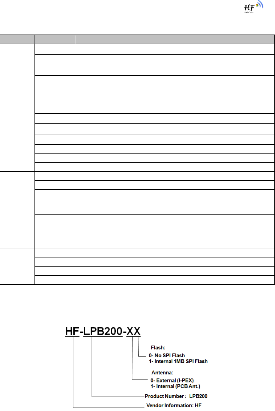
2.1.5. Order Information
Base on customer detailed requirement, HF-LPB200 series modules provide different variants and
physical type for detailed application.
Figure 7. HF-LPB200 Order Information
Function
Name
Description
External
Interface
COM1
Main data/command RS-232 interface
RS485
Main data/command RS-485 interface
JTAG
JTAG/JLink debug interface
USB2TTL
UART to USB debug interface. (For PC without RS232, need load
driver). Can be power input.
USB DEBUG
HF-LPB200 USB2.0 data interface (Reserved for future use)
DC Jack
DC jack for power in, 5~18V input.
DC5-18V
DC jack for power in, 5~18V input.
BAT
2 Li-Battery Power Supply.
EXT PORT
HF-LPB200 GPIO function extend interface connector
JMP2
Boot up option. Add jumper when download image through UART.
JMP3
4Pin USB or RS232 Jumper. Left jump when select USB.
JMP6
3Pin RS485 Jumper. No jump when selects RS232.
LED
Power
3.3V Power Indicator
nLink
nLink -WiFi LINK Indicator
nReady
nReady – Module Bootup Ready Indicator
On (“low”)- Module bootup OK; Off (“high”)- Mouule botup failed;
Twinkle- Remote Upgrade Ongoing;
Sleep_ON
Sleep_ON-Module asleep or awake Indicator
On (“low”)- Module in shundown(deep sleep) status;
Off (“high”)- Mouule in normal status;
Twinkle- Bootloader Upgrade Ongoing;
Button
nReset
Used to reset the module.
nReload
Restore factory configuration after push this pin more than 3s.
WPS
WPS Button
Sleep_RQ
Pin Sleep Control, more than 1s to put module in standby mode.
HF-LPB200 Low Power WiFi Module User Manual
Shanghai High-Flying Electronics Technology Co., Ltd
www.hi-flying.com
- 16 -
2.2. Typical Application
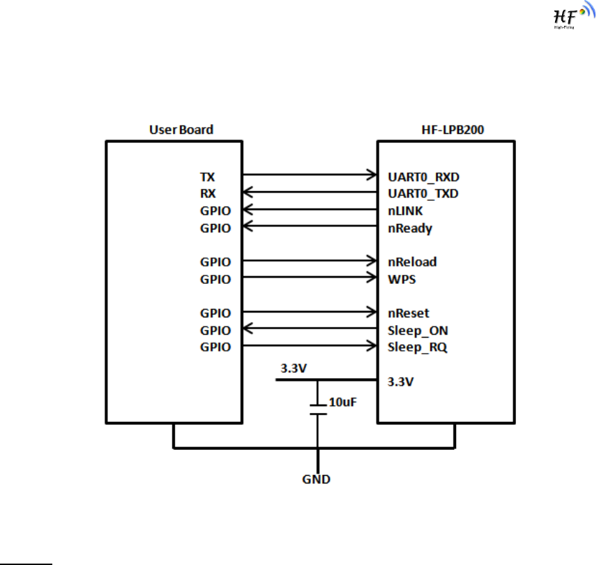
2.2.1. Hardware Typical Application
Figure 8. HF-LPB200 Hardware Typical Application
Notes:
nReset- Module hardware reset signal. Input. Logics “0” effective.
There is pull-up resister internal and no external pull-up required. When module power up or some
issue happened, MCU need assert nRST signal “0” at least 10ms, then set” 1” to keep module fully
reset.
nLink- Module WIFI connection status indication. Output.
When module connects to AP (AP associated), this pin will output “0”. This signal used to judge if
module already at WiFi connection status. Thers is pull-up resister internal and no external pull-up
required. If nLink function not required, can leave this pin open.
nReady- Module boot up ready signal. Output. Logics “0” effective.
The module will output “0” after normal boot up. This signal used to judge if module finish boot up and
ready for application or working at normal mode. If nReady function not required, can leave this pin
open.
nReload- Module restore to factory default configuration.Input. Logics “0” effective.
User can de-assert nReload signal “0” more than 3s through button or MCU pin, then release, module
will restore to factory default configuration and re-start boot up process.
HF-LPB200 Low Power WiFi Module User Manual
Shanghai High-Flying Electronics Technology Co., Ltd
www.hi-flying.com
- 17 -
Sleep-RQ- Module Pin Sleep Control. Input.
The user should de-assert this pin low “0”, after 1‟s assert to high ”1” to put the module to sleep status.
Also at the deep sleep/standby mode, user can de-assert this pin low “0”, after 1‟s assert to high ”1” to
put the module to wake up the module.
Sleep-ON- Module Pin Sleep Indicator. Output.
This pin is used to indicate that the module is asleep (Module output “0”) or awake (Module output “1”)
status. If user doesn't use pin sleep function, can leave this pin open.
UART0_TXD/RXD- UART port data transmit and receive signal.
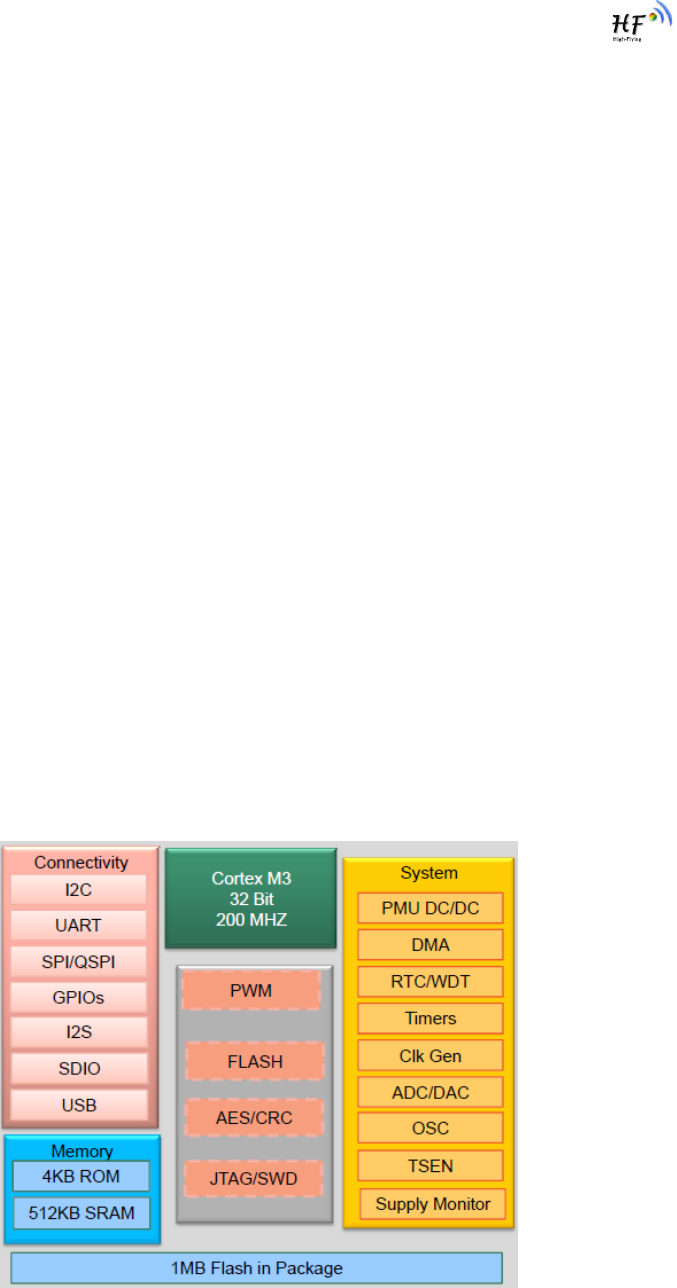
2.2.2. Internal MCU Hardware Feature
MCU and hardware Key Features as following for customized application:
ARM Cortex‐M3 Core, Up to 200Mhz;
1MB in-package QSPI Flash, 512KB SRAM;
SPI Extend 1MB flash available;
Multiple power down mode w/ SRAM Retention;
Configurable GPIO function (Module output);
ADC 16 bit, 2 channel;
PWM, 4 channel;
One I2C interface;
One SPI/I2S/UART interface;
One USB OTG FS2.0 interface;
RTC extend interface;
Figure 9. HF-LPB200 Internal MCU Hardware Architecture
HF-LPB200 Low Power WiFi Module User Manual
Shanghai High-Flying Electronics Technology Co., Ltd
www.hi-flying.com
- 18 -
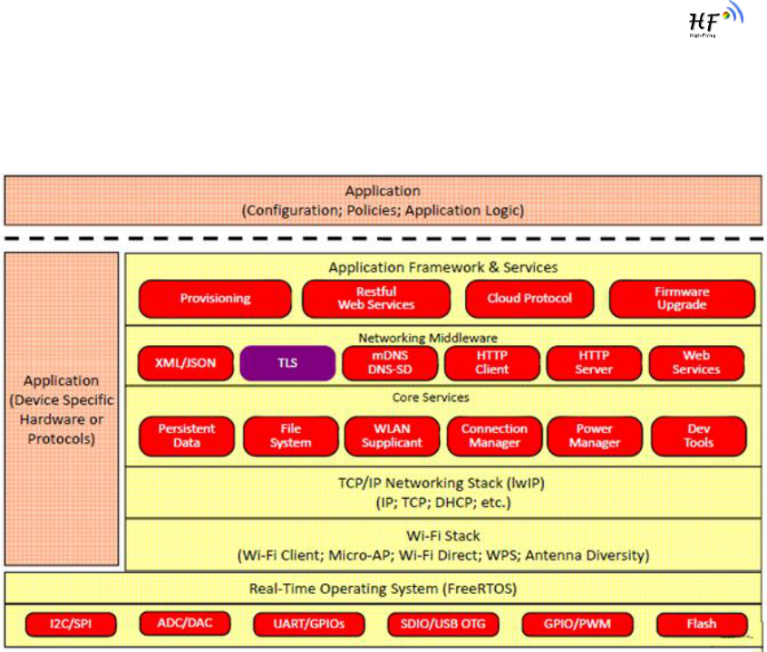
2.2.3. Software SDK Architecture
HF-LPB software platform as following picture and High-Flying will provide full SDK for customer
application development.
Detailed SDK introduction refer to SDK API interface and user guide document.
Figure 10. HF-LPB200 Software SDK Architecture
HF-LPB200 Low Power WiFi Module User Manual
Shanghai High-Flying Electronics Technology Co., Ltd
www.hi-flying.com
- 19 -
3. FUNCTIONAL DESCRIPTION
3.1. Wireless Networking
HF-LPB200 module can be configured as both wireless STA and AP base on network type. Logically
there are two interfaces in HF-LPB200. One is for STA, and another is for AP. When HF-LPB200
works as AP, other STA equipments are able to connect to wireless LAN via HF-LPB200 module.
Wireless Networking with HF-LPB200 is very flexible.
Notes:
AP: that is the wireless Access Point, the founder of a wireless network and the centre of the network
nodes. The wireless router we use at home or in office may be an AP.
STA: short for Station, each terminal connects to a wireless network (such as laptops, PDA and other
networking devices) can be called with a STA device.
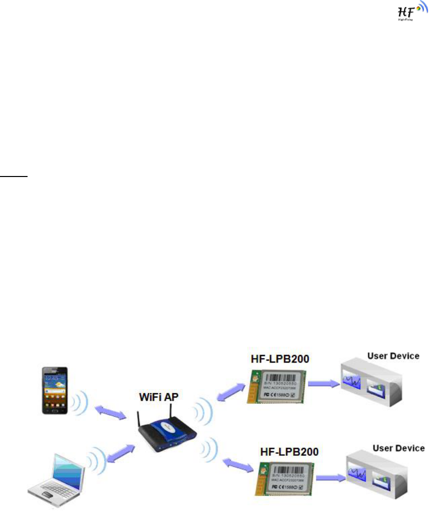
3.1.1. Basic Wireless Network Based On AP (Infrastructure)
Infrastructure: it‟s also called basic network. It built by AP and many STAs which join in.
The characters of network of this type are that AP is the centre, and all communication between STAs
is transmitted through the AP. The figure following shows such type of networking.
Figure 11. HF-LPB200 Basic Wireless Network Structure
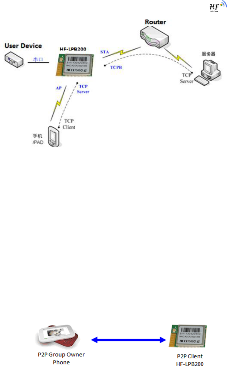
3.1.2. Wireless Network Based On AP+STA
HF-LPB200 module support AP+STA network mode, means module support one AP interface and one
STA interface at the same time, as following figure,
HF-LPB200 Low Power WiFi Module User Manual
Shanghai High-Flying Electronics Technology Co., Ltd
www.hi-flying.com
- 20 -
Figure 12. HF-A11 AP+STA Network Structure
When module enables AP+STA function, Module‟s STA interface can connect with router and connect
to TCP server in the network. At the same time, module‟s AP interface is also active and permit
phone/PAD to connect through TCPB, then phone/PAD can control user device and and setting the
module parameters,
The advantage of AP+STA mode is:
Users can easily setting and track user device through Phone/PAD and not change the
orginal network setting.
Users can easily setting module‟s parameters through WiFi when module works as STA
mode.
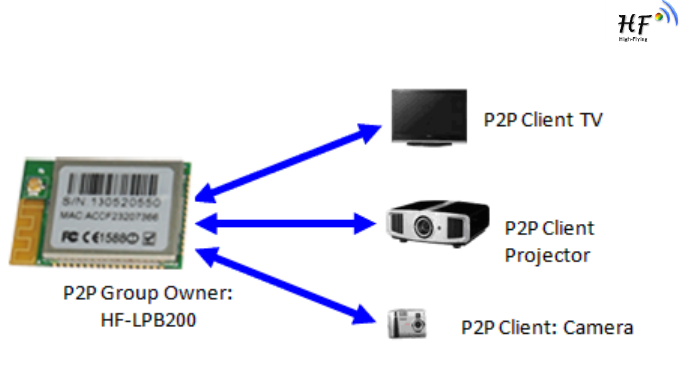
3.1.3. Wi-Fi Direct Network
Wi-Fi Direct standard permits the wireless connection without AP router. Like blue tooth, this standard
use point to point interconnection and all devices connect each other and transmit data withour router.
HF-LPB200 module support following Wi-Fi Direct networking:
1:1 P2P Networking;
1:N P2P Networking (TBD);
Figure 13. HF-LPB200 1:1 P2P Networking
HF-LPB200 Low Power WiFi Module User Manual
Shanghai High-Flying Electronics Technology Co., Ltd
www.hi-flying.com
- 21 -
Figure 14. HF-LPB200 1:N P2P Networking
3.2. Work Mode : Transparent Transmission Mode
HF-LPB200 module support serial interface transparent transmission mode. The benefit of this mode
is achieves a plug and play serial data port, and reduces user complexity furthest. In this mode, user
should only configure the necessary parameters. After power on, module can automatically connect to
the default wireless network and server.
As in this mode, the module's serial port always work in the transparent transmission mode, so users
only need to think of it as a virtual serial cable, and send and receive data as using a simple serial. In
other words, the serial cable of users‟ original serial devices is directly replaced with the module; user
devices can be easy for wireless data transmission without any changes.
The transparent transmission mode can fully compatible with user‟s original software platform and
reduce the software development effort for integrate wireless data transmission.
The parameters which need to configure include:
Wireless Network Parameters
Wireless Network Name(SSID)
Security Mode
Encryption Key
TCP/UDP Linking Parameters
Protocol Type
Link Type(Server or Client)
Target Port ID Number
Target Port IP Address
Serial Port Parameters
Baud Rate
Data Bit
Parity (Check) Bit
Stop Bit
Hardware Flow Control

HF-LPB200 Low Power WiFi Module User Manual
Shanghai High-Flying Electronics Technology Co., Ltd
www.hi-flying.com
- 22 -
3.3. UART Frame Scheme
HF-LPB200 support UART free-frame function. Module will check the intervals between any two bytes
when reciving UART data. If this interval time exceeds defined value (50ms default), HF-LPB200 will
think it as the end of one frame and transfer this free-frame to WiFi port, or HF-LPB200 will receive
UART data untill 1400 bytes, then transfer 1400 bytes frame to WiFi port.
HF-LPB200‟s default interval time is 50ms. User can also set this interval to fast (10ms) through AT
command. But user have to consider if user MCU can send UART data with 10ms interval ,or the
UART data may be divide as fragment.
Through AT command: AT+UARTTE=fash/normal, user can set the interval time: fast (10ms) and
normal (50ms).
3.4. Encryption
Encryption is a method of scrambling a message that makes it unreadable to unwanted parties, adding
a degree of secure communications. There are different protocols for providing encryption, and the HF-
LPB200 module supports following:
WEP
WPA-PSK/TKIP
WPA-PSK/AES
WPA2-PSK/TKIP
WPA2-PSK/AES
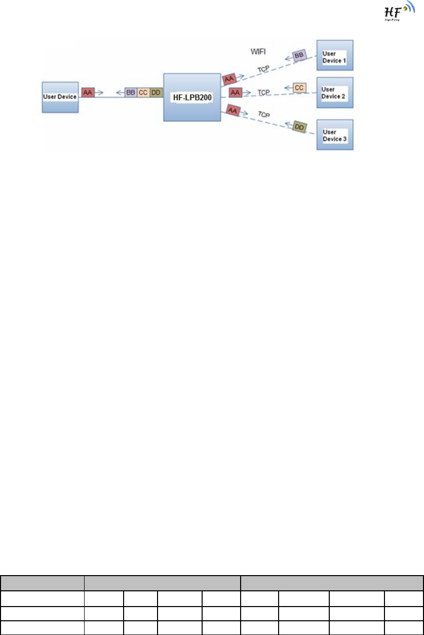
3.5. Multi-TCP Link Connection
When HF-LPB200 module configured as TCP Server, it supports Multi-TCP link connection, and
maximum eight TCP clients permit to connect to HF-LPB200 module. User can realize multi-TCP link
connection at each work mode.
Multi-TCP link connection will work as following structure:
Upstream:
All dates from different TCP connection or client will be transmitted to the serial port as a sequence.
Downstream:
All data from serial port (user) will be duplicate and broadcast to every TCP connection or client.
Detailed multi-TCP link data transmition structure as following figure:
HF-LPB200 Low Power WiFi Module User Manual
Shanghai High-Flying Electronics Technology Co., Ltd
www.hi-flying.com
- 23 -
Figure 15. Multi-TCP Link Data Transmition Structure
3.6. Power Save Scheme
HF-LPB200 module can work at three modes based on different power save scheme:
Normal Mode (Active/Sleep) - AP Associated, Wi-Fi ON/OFF based on internal control
Wi-Fi Wakeup Mode (Standby) - AP Associated, MCU OFF, Wi-Fi wakeup
Deep Sleep Mode (Shutdown) - Non AP Associated, Wi-Fi Shut dwon, MCU Sleep
Pin/Timer Wakeup
Normal Mode (Active/Sleep) Normal mode means Wi-Fi circuitry works at IEEE PS mode and MCU
circuitry work at normal mode. That‟s the default working mode for HF-LPB200 to communication with
outside and no data transceiving latency.
Wi-Fi Wakeup Mode (Standby) allows the MCU circuitry to be powered down and still keep Wi-Fi AP
associated, which save more power compared with normal mode and module can be wake up through
Wi-Fi at network server side.
Deep Sleep Mode (Shutdown) allows the Wi-Fi circuitry and MCU circuitry to be powered down,
which results in the lowest sleep current, but at the expense of longer wake up times. This is due to the
module associating with the access point every time when it wakes up. The intent of this option is to
allow for longer sleep times. Deep sleep mode can trigger “Sleep_RQ” pin to go in.
The Difference between Wi-Fi Wakeup and Deep Sleep mode as follows:
Table 6 Difference between Wi-Fi Wakeup Mode and Standb Deep Sleep Mode
Module Status
Wake Up Method
Wi-Fi
MCU
Current
UART
GPIO
Timeout
AT Com.
Wi-Fi
Wi-Fi Wakeup
ON
OFF
<10mA
OFF
Yes
Yes
No
Yes
Deep Sleep
OFF
OFF
1mA
OFF
Yes
Yes
No
No
Following typical measurement parameters can be used for select suitable power save scheme based
on the real application case:

HF-LPB200 Low Power WiFi Module User Manual
Shanghai High-Flying Electronics Technology Co., Ltd
www.hi-flying.com
- 24 -
Table 7 Power Consumption with Different Power Save Mode
WiFi Mode
Condition
Average Current
Peak Current
Deep Sleep
Wi-Fi/MCU Shutdown
< 100uA
< 100uA
Wi-Fi Wakeup
MCU Shundown
~10mA
< 200mA
Normal
(Active/Sleep)
WiFi ON - AP Associated
DTIM = 100ms, No Data
~21mA
< 250mA
Normal
(Active/Sleep)
WiFi ON - AP No-Assoiated
DTIM = 100ms, No Data
~27mA
< 250mA
Normal
(Active/Sleep)
WiFi ON – AP Connected
DTIM = 100ms, Date:1KB/s
~50mA
< 250mA
In addition, for Wi-Fi Wakeup/Deep Sleep mode, module provides three wakes up options, user can
select one or whole as the module wake up option. Refer to AT Instruction (Power Management
Instruction Set) for more detailed setting.
Pin (Sleep_RQ) Wake Up
Timeout Wake Up
Wi-Fi Wake Up
Pin Wake Up Option allows an external microcontroller to determine when HF-LPB200 should sleep
and when it should wake by controlling the “Sleep_RQ” and “Sleep_ON” pin. at the Wi-Fi wakeup
mode/Deep Sleep mode, user can de-assert this pin low “0”, after 1‟s assert to high ”1” to put the
module to wake up the module. If user doesn't use pin sleep function, can leave this pin open.
Timeout Wake Up Option allows the sleep timeout period to be configured through the use of AT
Instruction.In this option, the module will exit sleep based on the <Timeout> AT Instruction parameters
Wi-Fi Wake Up Option only applicatable for Wi-Fi Wakeup mode, which provide the flexibility for
network server or user to control and manage the Wi-Fi device to go into power save mode, but still
keep the Wi-Fi link associated, Refer to AT Instruction to know more about the WiFi wakeup command.
3.7. Parameters Configuration
HF-LPB200 module supports two methods to configuration parameters: Web Accessing and
AT+instruction set.
Web accessing means users can configure parameters through Web browser. When HF-LPB200
module connected to wireless network, parameters configuration is done on a PC connected to the
same wireless network.
AT+instruction set configuration means user configure parameters through serial interface command.
Refer to “AT+instruction set” chapter for more detail.
3.8. Firmware Update
HF-LPB200 module supports two on-line upgrade methods:
Webpage Wi-Fi Upgrade
Remote Upgrade

HF-LPB200 Low Power WiFi Module User Manual
Shanghai High-Flying Electronics Technology Co., Ltd
www.hi-flying.com
- 25 -
Webpaged based Wi-Fi upgrade, please refer to 3.1.8 firmware upgrade page, user can upload
firmware file from PC to HF-LPB200.
HF-LPB200 module also support upgrade from remote HTTP server, keep module connects to AP
router before excuate remote HTTP upgrade. Remote upgrade have two methods: Direct Download
and Upgrade, Configure File Based Upgrade.
Configure File Based Upgrade
AT+UPURL command to set the remote directory which the configuration file located, such as
AT+UPURL=http://www.hi-flying.com/!admin/down/
Notes: The last ‟/‟ can‟t be remove
AT+UPFILE command to set the configuration file name, such as AT+UPFILE=config.txt
AT+UPST command to start remote upgrade. After excuate this command, the module will firstly
download configuration file (“config.txt”), then download the upgrade file base on the URL address
listed in the configure file.
General “config.txt” file format as following example:
[URL]=”http://www.hi-flying.com/!admin/down/20133181764087523.zip”
Direct Download and Upgrade
AT+UPURL command to set the remote directory and file name, such as:
AT+UPURL=http://www.hi-flying.com/!admin/down/,lpb.bin
After excuate this command, the module will directly download the “lpb.bin” file from remote directory
and start upgrade.
Notes: please contact with high-flying technical people before upgrade firmware, or maybe damage
the module and can‟t work again.
3.9. GPIO Function
HF-LPB200 module can provide maximum 17 GPIO pins, which include following configurable
interface application:
Two A/D analog input pins, dual channel, 16-bit ADC with sample rate upto 250KHz;
Four PWM ouput pins (4 channel);
32.768KHz Crystal input for RTC function support;
Two Pin sleep control pins for low power application;
One WPS functional pin;
One I2C interace;
One General Serial Communication Port, which can configured as
Master/Slave SPI Interface;
UART2 Interface with flow control;
I2S audio interface;
HF-LPB200 GPIO pin map as following table:

HF-LPB200 Low Power WiFi Module User Manual
Shanghai High-Flying Electronics Technology Co., Ltd
www.hi-flying.com
- 26 -
Table 7 HF-LPB200 GPIO Pin Mapping Table
User need get HF-LPB200 SDK to configure these GPIOs to different functions. Please contact high-
flying technical people to acquire more information.
When module works at GPIO mode, PC and other equipts can setup connection (TCP/UDP) through
Wi-Fi, then read/write GPIO information through command.
GPIO n IN, Set GPIOn as input, Response GPIO OK or GPIO NOK;
GPIO n OUT 0, Set GPIOn as output and output „0‟, Response GPIO OK or GPIO NOK;
GPIO n OUT 1, Set GPIOn as output and output „1‟, Response GPIO OK or GPIO NOK;
GPIO n SW, Set GPIOn as output and switch the output status, Response GPIO OK or
GPIO NOK;
GPIO n PWM m1 m2, Set GPIOn output a wave: m1 is „high‟ duration and m2 is ‟low‟
duration (Time unit is „ms‟ and minimal is 10ms), Response GPIO OK or GPIO NOK;
GPIO n GET, Read GPIOn status, Response I0,I1,O0,O1, means”input low”,”input
high”,”output low”,”output high”
Notes: Some SW version may not include these GPIO command set.please contact with high-flying
technical people.
3.10. Analog Digital Converter (ADC) Function
HF-LPB200 integrate two identical ADCs (ADC0 and ADC1) which be programmed separately.The
ADC is a second oeder sigma-delta converter with up to 16-bit resolution. The conversion results can
be written to memory through DMA. Several modes of operation are available for the ADC.
The main features of ADC are follows:
Selectable decimation rates with also set the effective resolution 910 to 16 bits);
GPIO
Function 1
Function 2
Default Setting
Describtion
GPIO7
Sleep_RQ
GPIO
Sleep_RQ
Sleep Control
Function Pins
GPIO8
Sleep_ON
GPIO
Sleep_ON
GPIO10
WPS
GPIO
WPS
WPS functional pin
GPIO11
A/D Input 1
GPIO
GPIO11
16-Bits ADC input pins
Dual ADC input
GPIO12
A/D Input 2
GPIO
GPIO12
GPIO13
OSC32K_IN
GPIO
GPIO13
External 32.768KHz
RTC clock input option
GPIO14
OSC32K_OUT
GPIO
GPIO14
GPIO18
PWM 1
ADC2 Vfef
GPIO18
PWM functiona pins
output.
GPIO20
PWM 2
GPIO
GPIO20
GPIO23
PWM 3
GPIO
GPIO23
GPIO24
PWM 4
GPIO
GPIO24
GPIO25
I2C_SCL
GPIO
GPIO25
I2C Bus Interface
GPIO26
I2C_SDA
GPIO
GPIO26
GPIO27
SPI_MISO
UART2_TXD
GPIO27
Three Functions:
<1> SPI Master/Slave
<2> UART w flow ctl
<3> I2S Interface
GPIO28
SPI_CLK
UART2_CTS
GPIO28
GPIO29
SPI_CS
UART2_RTS
GPIO29
GPIO30
SPI_MOSI
UART2_RXD
GPIO30

HF-LPB200 Low Power WiFi Module User Manual
Shanghai High-Flying Electronics Technology Co., Ltd
www.hi-flying.com
- 27 -
Throughput rate as fast as 4uS(250KHz);
PGA setting support: 2x, 1x, and 0.5x;
Reference voltage (Vref): interface reference 1.2V;
Offset and gain calibration;
Embedded temperature sensor with internal or external diode options;
Interrupt generation and/or DMA request;
GPIO n OUT 0, Set GPIOn as output and output „0‟, Response GPIO OK or GPIO NOK;
HF-LPB200 Low Power WiFi Module User Manual
Shanghai High-Flying Electronics Technology Co., Ltd
www.hi-flying.com
- 28 -
4. OPERATION GUIDELINE
4.1. Configuration via Web Accessing
When first use HF-LPB200 modules, user may need some configuration. User can connect to HF-
LPB200 module‟s wireless interface with following default setting information and configure the module
through laptop.
Table 8 HF-LPB200 Web Access Default Setting
Parameters
Default Setting
SSID
HF-LPB200
IP Address
10.10.100.254
Subnet Mask
255.255.255.0
User Name
Admin
Password
Admin
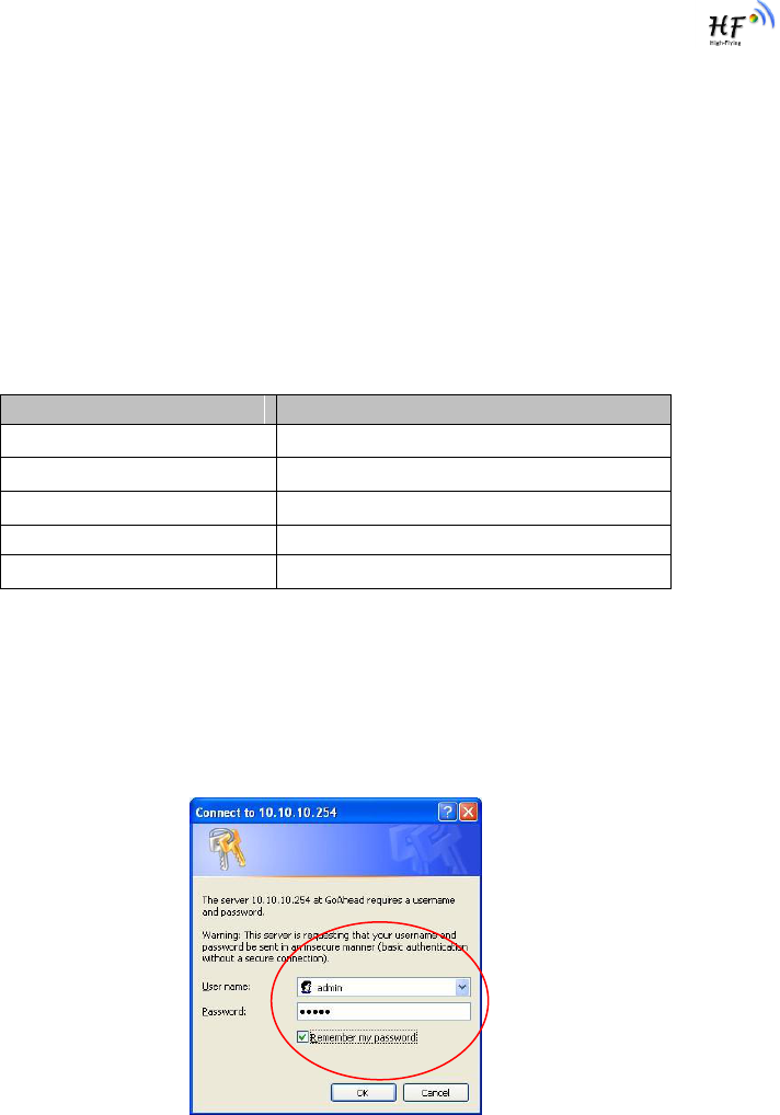
4.1.1. Open Web Management Interface
Step 1: Connect laptop to SSID “HF-LPB200” of HF-LPB200 module via wireless LAN card;
Step 2: After wireless connection OK. Open Wen browser and access “http://10.10.100.254”;
Step 3: Then input user name and password in the page as following and click “OK” button.
Figure 16. Open Web Management page
The HF-LPB200 web management page support English and Chinese language. User can select
language environment at the top right corner and click “Apply” button.
The main menu include nine pages: “System”, “Work Mode”, “STA Setting”, “AP Setting”, “Other
Setting”, “Account”, “Upgrade SW”, “Restart”, “Restore”.
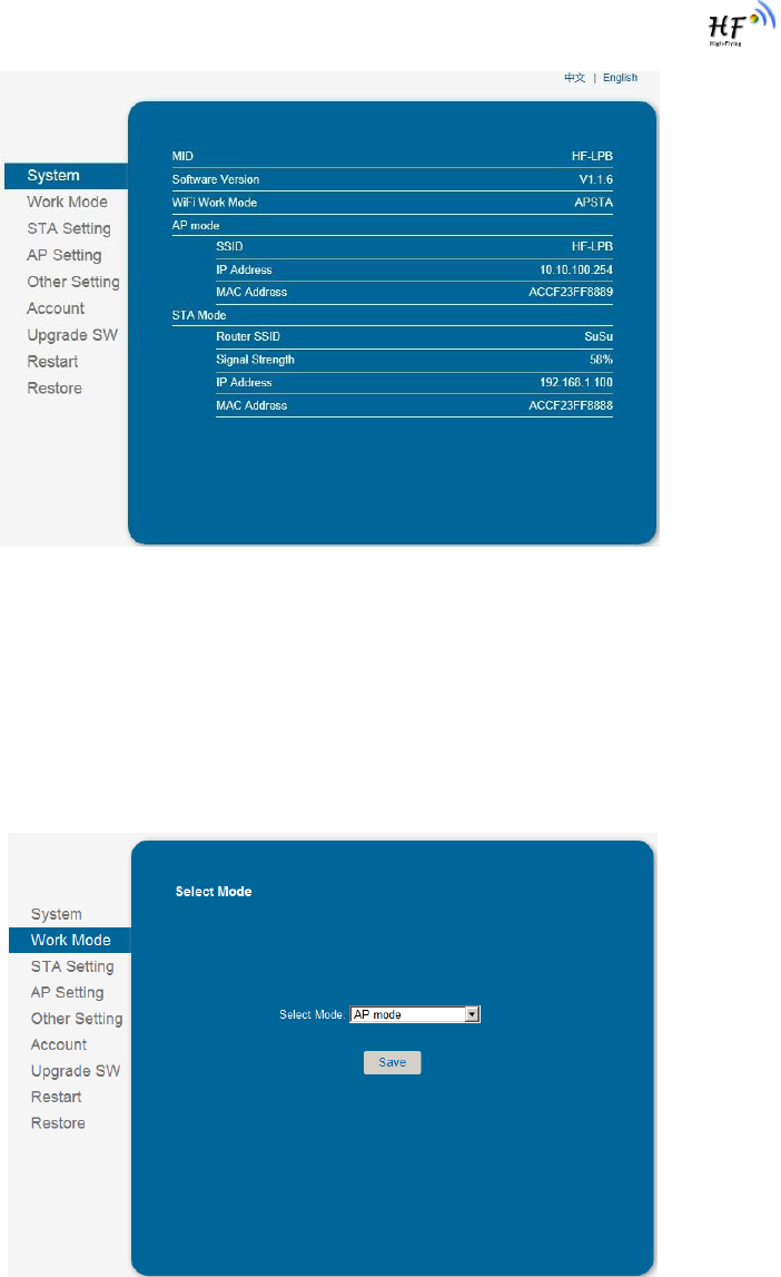
4.1.2. System Page
At this page, user can check current device‟s important information and status such as: device ID
(MID), software version, wireless work mode and related Wi-Fi parameters.
HF-LPB200 Low Power WiFi Module User Manual
Shanghai High-Flying Electronics Technology Co., Ltd
www.hi-flying.com
- 29 -
Figure 17. System Web Page
4.1.3. Work Mode Page
HF-LPB200 module can works at AP mode to simplify user‟s configuration, can also works at STA to
connect remote server through AP router. Also, it can configure at AP+STA mode which provide very
flexible application for customers.
Figure 18. Work Mode Page
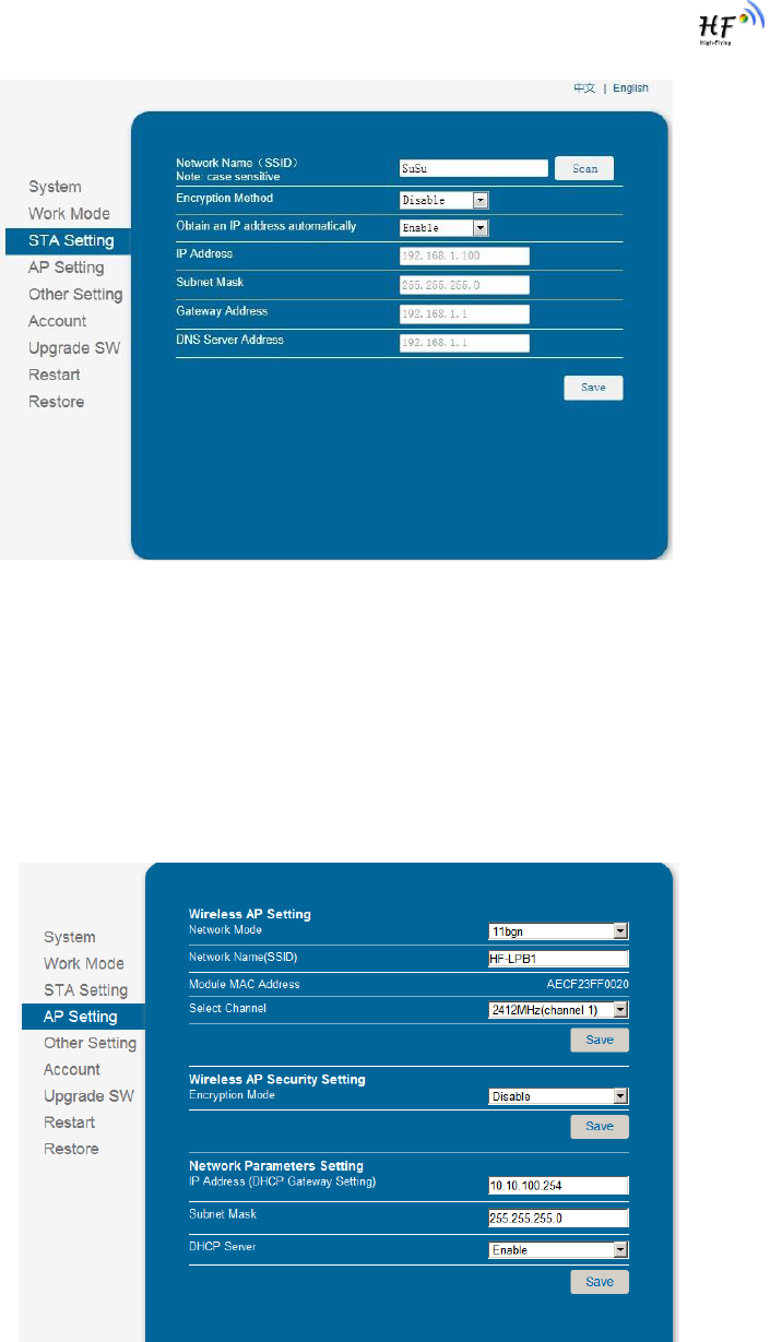
4.1.4. STA Setting Page
User can push “Scan” button to auto search Wi-Fi AP router nearby, and can connect with associate
AP through some settings. Please note the encryption information input here must be fully same with
Wi-Fi AP router‟s configration, and then it can link with AP correctly.
HF-LPB200 Low Power WiFi Module User Manual
Shanghai High-Flying Electronics Technology Co., Ltd
www.hi-flying.com
- 30 -
Figure 19. STA Setting Page
4.1.5. AP Setting Page
When user select module works at AP and AP+STA mode, then need setting this page and provide
wireless and network parameters. Most of the system support DHCP to achieve IP address, so we
suggest to “Enable” DHCP server in most applications.
Figure 20. AP Setting Page
HF-LPB200 Low Power WiFi Module User Manual
Shanghai High-Flying Electronics Technology Co., Ltd
www.hi-flying.com
- 31 -
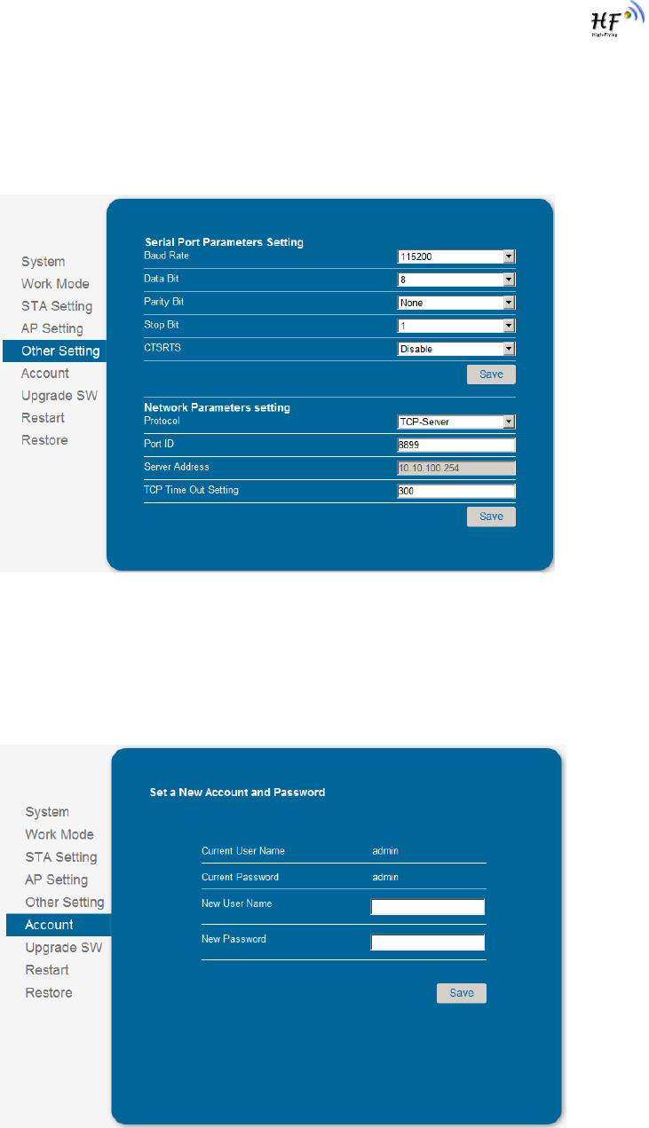
4.1.6. Other Setting Page
HF-LPB200 usually works at data transparent transmission mode. At this mode, the user device which
connected with HF-LPB200 will connect and communicate with remote PC or server. At this page, user
need setting serial port communication parameters and defines TCP related protocal parameters.
Figure 21. Other Setting Page
4.1.7. Account Management Page
This page set web server‟s user name and password.
Figure 22. Account Page

HF-LPB200 Low Power WiFi Module User Manual
Shanghai High-Flying Electronics Technology Co., Ltd
www.hi-flying.com
- 32 -
4.1.8. Upgrade Software Page
User can upgrade new software (firmware) version through Wi-Fi.
Figure 23. Upgrade SW page
4.1.9. Restart Page
Most of the settting and configuration can only effective after system restart. User shall restart after
finish all setting.
Figure 24. Restart Page
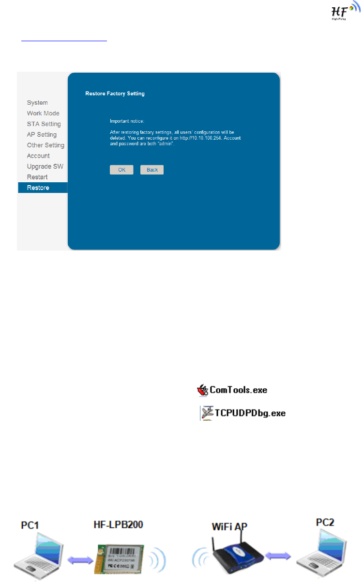
4.1.10. Restore Page
After module restore factory default setting, all user configuration profile will lose.
HF-LPB200 Low Power WiFi Module User Manual
Shanghai High-Flying Electronics Technology Co., Ltd
www.hi-flying.com
- 33 -
User can access http://10.10.100.254 to set again, and user name and password is “admin”. HF-
LPB200 will restore to AP mode for factory default setting.
Figure 25. Restore Page
4.2. HF-LPB200 Usage Introduction
4.2.1. Software Debug Tools
High-Flying use two common software tools debugging and applying HF-LPB200 module.
(User can also select other tools used to debug serial port).
Serial Debugging Software: ComTools
Ethernet Debugging Software: TCPUDPDbg
4.2.2. Network Connection
User can select two methods to connect HF-LPB200 module base on dedicated application.
Use HF-LPB200 STA interface. HF-LPB200 and debug PC2 connect to a wireless AP,
another PC1 (or user device) connect to HF-LPB200 module with serial port:
Figure 26. STA Interface Debug Connection
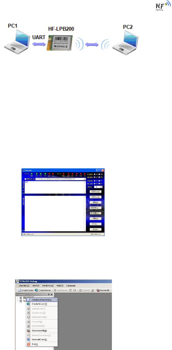
Use HF-LPB200 AP interface. Debug PC2 connect to HF-LPB200 through wireless
connection, another PC1 (or user device) connect to HF-LPB200 module with serial port.
HF-LPB200 Low Power WiFi Module User Manual
Shanghai High-Flying Electronics Technology Co., Ltd
www.hi-flying.com
- 34 -
Figure 27. AP Interface Debug Connection
4.2.3. Default Parameter Setting
Default SSID: HF-LPB200;
Deault security mode: open,none;
User UART parameter setting:115200,8,1,None;
Default network parameter setting:TCP,Server,8899,10.10.100.254;
Module IP address: dhcp,0.0.0.0,0.0.0.0,0.0.0.0;
4.2.4. Module Debug
PC1 open “CommTools” program, setting the same serial port parameters with HF-LPB200 module
and open serial port connection.
Figure 28. “CommTools” Serial Debug Tools
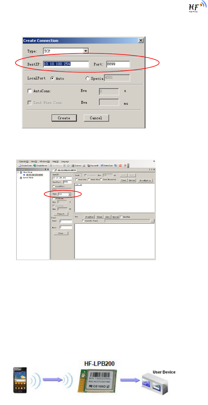
PC2 open “TCPUDPDbg” program, and create a new connection. If HF-LPB200 configured as Server
mode, “TCPUDPDbg” Tools shall create “Client “mode connection. Or otherwise, create a “Server”
mode connection.
Figure 29. “TCPUDPDbg” Tools Create Connection
HF-LPB200 Low Power WiFi Module User Manual
Shanghai High-Flying Electronics Technology Co., Ltd
www.hi-flying.com
- 35 -
Then setting the TCP/UDP connection parameters. Default as following:
Figure 30. “TCPUDPDbg” Tools Setting
Then, click “Create” button to create a connection.
Figure 31. “TCPUDPDbg” Tools Connection
Now, in transparent transmission mode, data can be transferred from “CommTools” program to
“TCPUDPDbg” program, or in reverse. You can see data in receiver side will keep same as in sender
side.
4.3. Typical Application Examples
4.3.1. Wireless Control Application
Figure 32. Wireless Control Application
HF-LPB200 Low Power WiFi Module User Manual
Shanghai High-Flying Electronics Technology Co., Ltd
www.hi-flying.com
- 36 -
For this wireless control application, HF-LPB200 works as Ad-Hoc mode. Module‟s serial port connects
to user device. So, control agent (Smart phone for this example) can manage and control the user
device through the wireless connection with HF-LPB200 module.
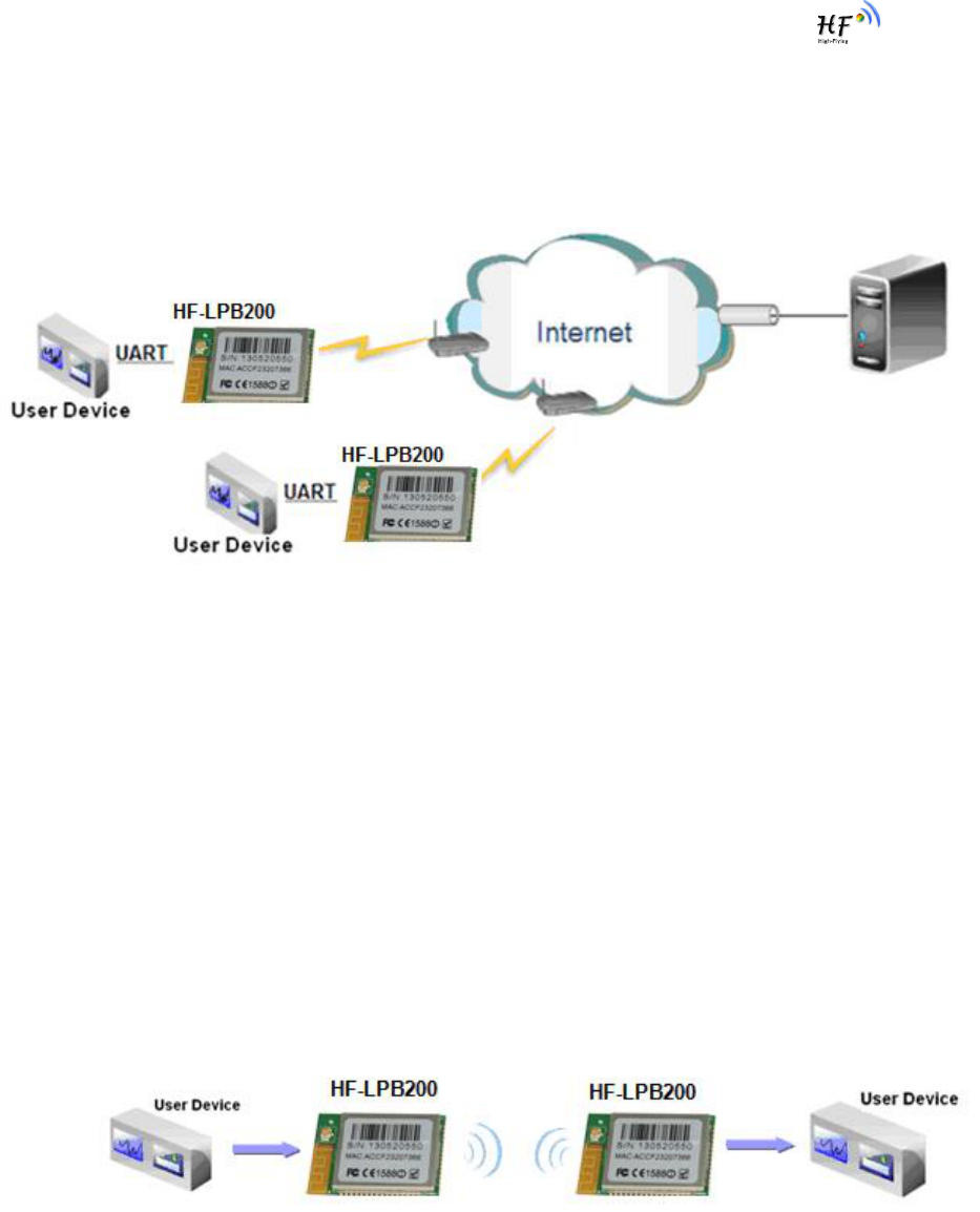
4.3.2. Remote Management Application
Figure 33. Remote Management Application
For this remote management application, HF-LPB200 works as STA mode and connects to Internet
through wireless AP. Module configured as TCP Client and communicates with remote TCP server at
Internet. Module‟s serial port connects to user device.
So, user device‟s data or sampling information can send to remote TCP server for storage or
processing. Also remote TCP server can send command to control and manage the user device
through the wireless network.
4.3.3. Transparent Serial Port Application
For this transparent serial port application, two HF-LPB200 modules connect as below figures to build
up a transparent serial port connection. HF-LPB200 works as Ad-Hoc mode to connect each other.
Figure 34. Transparent Serial Port Application
HF-LPB200 Low Power WiFi Module User Manual
Shanghai High-Flying Electronics Technology Co., Ltd
www.hi-flying.com
- 37 -
5. AT+INSTRUCTION INTRODUCTION
5.1. Configuration Mode
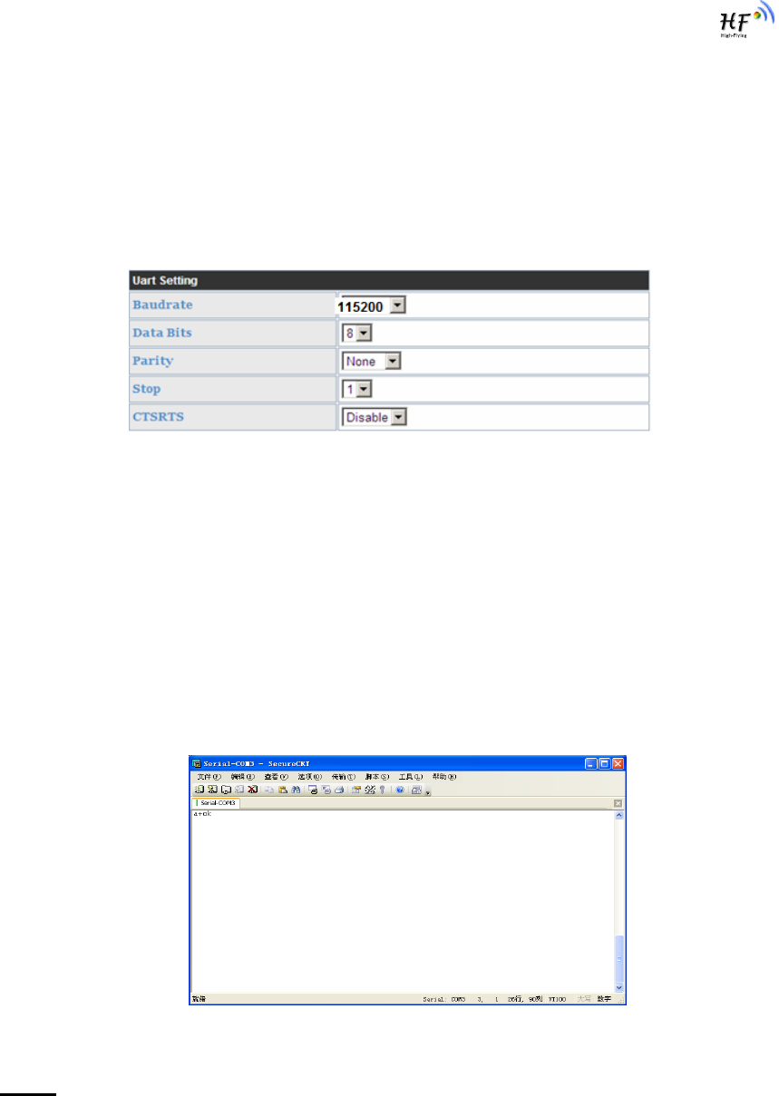
When HF-LPB200 power up, it will default works as transparent transmission mode, then user can
switch to configuration mode by serial port command. HF-LPB200 UART default parameters setting as
below figure,
Figure 35. HF-LPB200 Default UART Port Parameters
In configuration mode, user can setting the module through AT+ instruction set, which cover all web
page setting function.
5.1.1. Switch to Configuration Mode
Two steps to finish switching from transparent transmission mode to configuration mode.
UART input “+++”, after module receive “+++”, and feedback “a” as confirmation.
UART input “a”, after module receive “a” and feedback “+ok” to go into AT+
instruction set configuration mode.
Figure 36. Switch to Configuration Mode
Notes:
1. When user input “+++” (No “Enter” key required), the UART port will display feedback information “a”,
and not display input information”+++” as above UART display.
2. Any other input or wrong step to UART port will cause the module still works as original mode
(transparent transmission).
HF-LPB200 Low Power WiFi Module User Manual
Shanghai High-Flying Electronics Technology Co., Ltd
www.hi-flying.com
- 38 -
5.2. AT+ Instruction Set Overview
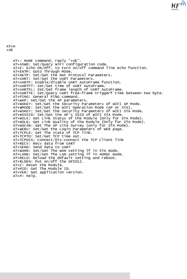
User can input AT+ Instruction through hyper terminal or other serial debug terminal, also can program
the AT+ Instruction to script. User can also input “AT+H” to list all AT+ Instruction and description to
start.
Figure 37. ”AT+H” Instruction for Help
5.2.1. Instruction Syntax Format
AT+Instruction protocol is based on the instruction of ASCII command style, the description of syntax
format as follow.
Format Description
< >: Means the parts must be included
[ ]: Means the optional part
Command Message
AT+<CMD>[op][para-1,para-2,para-3,para-4…]<CR>
AT+: Prefix of command message;
CMD: Command string;
[op]: Symbol of command operator,
“=” : The command requires parameters input;
“NULL”: Query the current command parameters setting;
[para-n]: Parameters input for setting if required;
<CR>:”Enter” Key, it‟s 0x0a or 0x0d in ASCII;

HF-LPB200 Low Power WiFi Module User Manual
Shanghai High-Flying Electronics Technology Co., Ltd
www.hi-flying.com
- 39 -
Notes: When input AT+Instruction, “AT+<CMD>” character will display capital letter automatic and
other parts will not change as you input.
Response Message
+<RSP>[op] [para-1,para-2,para-3,para-4…]<CR><LF><CR><LF>
+: Prefix of response message;
RSP: Response string;
“ok” : Success
“ERR”: Failure
[op] : =
[para-n]: Parameters if query command or Error code when error happened;
<CR>: ASCII 0x0d;
<LF>: ASCIII 0x0a;
Error Code
Table 9 Error Code Describtion
Error Code
Description
-1
Invalid Command Format
-2
Invalid Command
-3
Invalid Operation Symbol
-4
Invalid Parameter
-5
Operation Not Permitted
5.2.2. AT+ Instruction Set
Table 10 AT+ Instruction Set List
Instruction
Description
<null>
NULL
Managment Instruction Set
E
Open/Close show back function
WMODE
Set/Query Wi-Fi work mode (AP/STA/APSTA)
ENTM
Set module into transparent transition mode
TMODE
Set/Query module data transfer mode
MID
Query module ID information
VER
Query module software version information
RELD
Restore to factory default setting
Z
Re-start module
H
Help
Configure Parameters Instruction Set
CFGRD
Batch Read User Configure Parameters
CFGWR
Batch Write Configure Parameters
CFGFR
Batch Read Factory Default Configure Parameters
CFGTF
Copy User Parameters to Factory Default Parameters

HF-LPB200 Low Power WiFi Module User Manual
Shanghai High-Flying Electronics Technology Co., Ltd
www.hi-flying.com
- 40 -
UART Instruction Set
UART
Set/Query serial port parameters
UARTTE
Set/Query UART free-frame triggerf time between two bytes
Command Mode Set
SEND
Send Data at Command Mode
RECV
Receive Data at Command Mode
Network Instruction Set
PING
Network ”Ping” Instruction
NETP
Set/Query network protocol parameters
TCPLK
Query if TCP link already build-up
TCPTO
Set/Query TCP timeout
TCPDIS
Open/Close TCP link
Wi-Fi STA Instruction Set (Effective when module works as STA)
WSKEY
Set/Query STA security parameters
WSSSID
Set/Query associated AP SSID parameters
WANN
Set/Query STA‟s network parameters
WSMAC
Query STA‟s MAC address
WSLK
Query STA Wi-Fi link status
WSLQ
Query STA Wi-Fi signal strength
WSCAN
Scan AP
WSDNS
Set/Query STA‟s Static DNS server address
Wi-Fi AP Instruction Set (Effective when module works as AP)
LANN
Set/Query AP‟s network parameters
WAP
Set/Query AP Wi-Fi parameters
WAKEY
Set/Query AP security parameters
WAMAC
Set/Query AP MAC address
WADHCP
Set/Query AP DHCP Server status
WADMN
Set/Query AP webpage domain name
Webpage Management Instruction Set
WEBSWITCH
Set Webpage Option
PLANG
Set/Query Webpage Language Option
WEBU
Set/Query Webpage User name and Code
Remote Upgrade Instruction Set
UPURL
Set/Query remote upgrade URL address
UPFILE
Set/Query remote upgrade configure file name
UPST
Start remote upgrade
Power Management Instruction Set
MSLP
Set power save mode parameters
Others Instruction Set
WRMID
Set module ID
ASWD
Set/Query WiFi configuration code
5.2.2.1. AT+E
Function: Open/Close show back function;
Format:
AT+E<CR>
+ok<CR>< LF ><CR>< LF >

HF-LPB200 Low Power WiFi Module User Manual
Shanghai High-Flying Electronics Technology Co., Ltd
www.hi-flying.com
- 41 -
When HF-LPB200 module firstly switch from transparent transmission to configuration mode, show
back status is open, input “AT+E” to close show back function, input“AT+E” again to open show back
function.
5.2.2.2. AT+WMODE
Function: Set/Query WIFI work mode;
Format:
Query Operation
AT+WMODE<CR>
+ok=<mode><CR>< LF ><CR>< LF >
Set Operation
AT+ WMODE=<mode><CR>
+ok<CR>< LF ><CR>< LF >
Parameters:
mode:Wi-Fi work mode
AP
STA
APSTA
5.2.2.3. AT+ENTM
Function: Set module into transparent transmition mode;
Format:
AT+ENTM<CR>
+ok<CR>< LF ><CR>< LF >
When operate this command, module switch from configuration mode to transparent transmission
mode.
5.2.2.4. AT+TMODE
Function: Set/Query module data transfer mode.
Format:
Query Operation
AT+TMODE<CR>
+ok=<tmode><CR>< LF ><CR>< LF >
Set Operation
AT+TMODE=<tmode><CR>
+ok<CR>< LF ><CR>< LF >
Parameters:
tmode: data transfer mode, include:
throughput
cmd
5.2.2.5. AT+MID
Function: Query module ID information;
Format:

HF-LPB200 Low Power WiFi Module User Manual
Shanghai High-Flying Electronics Technology Co., Ltd
www.hi-flying.com
- 42 -
Query Operation
AT+MID<CR>
+ok=<module_id><CR>< LF ><CR>< LF >
Parameters:
module_id: Module ID information;
HF-LPB200;
Notes: User can set this parameter through AT+WRMID.
5.2.2.6. AT+VER
Function: Query module software version information;
Format:
Query Operation
AT+VER<CR>
+ok=<ver><CR>< LF ><CR>< LF >
Parameters:
ver: Module software version information;
5.2.2.7. AT+RELD
Function: module restore to factory default setting;
Format:
Set Operation
AT+ RELD<CR>
+ok=rebooting…<CR>< LF ><CR>< LF >
When operate this command, module will restore to factory default setting and reboot.
5.2.2.8. AT+Z
Function: Re-start module;
Format:
AT+ Z<CR>
5.2.2.9. AT+H
Function: Help;
Format:
Query Operation
AT+H<CR>
+ok=<command help><CR>< LF ><CR>< LF >
Parameters:
command help: command introduction;
5.2.2.10. AT+CFGRD
Function: Batch Read User Configure Parameters;
Format:
Query Operation
AT+CFGRD<CR>

HF-LPB200 Low Power WiFi Module User Manual
Shanghai High-Flying Electronics Technology Co., Ltd
www.hi-flying.com
- 43 -
+ok=<config><CR>< LF ><CR>< LF >
Parameters:
config: the first two bytes means the length of configuration parameters;
5.2.2.11. AT+CFGWR
Function: Batch Write User Configure Parameters;
Format:
Set Operation
AT+CFGWR=<config><CR>
+ok<CR>< LF ><CR>< LF >
Parameters:
config: the first two bytes means the length of configuration parameters;
5.2.2.12. AT+CFGFR
Function: Batch Read Factory Default Configure Parameters;
Format:
Query Operation
AT+CFGFR<CR>
+ok=<config><CR>< LF ><CR>< LF >
Parameters:
config: the first two bytes means the length of configuration parameters;
5.2.2.13. AT+CFGTF
Function: Copy User Parameters to Factory Default Parameters;
Format:
Query Operation
AT+CFGTF<CR>
+ok=<status><CR>< LF ><CR>< LF >
Parameters:
status: feedback operation status;
5.2.2.14. AT+UART
Function: Set/Query serial port parameters;
Format:
Query Operation
AT+UART<CR>
+ok=<baudrate,data_bits,stop_bit,parity><CR>< LF ><CR>< LF >
Set Operation
AT+UART=<baudrate,data_bits,stop_bit,parity><CR>
+ok<CR>< LF ><CR>< LF >
Parameters:
baudrate:
300,600,1200,1800,2400,4800,9600,19200,38400,57600,115200.
data_bits:

HF-LPB200 Low Power WiFi Module User Manual
Shanghai High-Flying Electronics Technology Co., Ltd
www.hi-flying.com
- 44 -
8
stop_bits:
1,2
parity:
NONE
EVEN
ODD
Flowctrl: (CTSRTS)
NFC: No hardware flow control
FC: hardware flow control
5.2.2.15. AT+ UARTTE
Function: Set/Query UART free-frame trigger time between two bytes;
Format:
Query Operation
AT+ UARTTE<CR>
+ok=<mode><CR>< LF ><CR>< LF >
Set Operation
AT+ UARTTE=<mode><CR>
+ok<CR>< LF ><CR>< LF >
Parameters:
mode:
fast: free-frame trigger time between two bytes is 10ms;
normal: free-frame trigger time between two bytes is 50ms;
5.2.2.16. AT+ SEND
Function: Send Data at Command Mode.
Format:
AT+SEND=<data_lenth, data_content><CR>
+ok<CR>< LF ><CR>< LF >
Parameters:
data_lenth: Lenth of send data. Range: 0~1000 Byte
data_content: contents of send data.
When two parameters conflict, select smaller value to send data.
5.2.2.17. AT+ RECV
Function: Receive Data at Command Mode.
Format:
AT+RECV=<data_lenth><CR>
+ok=< data_lenth, data_content><CR>< LF ><CR>< LF >
Parameters:
data_lenth: Lenth of receive data. Range: 0~1000 Byte
data_content: contents of receive data.
If not receive any data in 3 second, then feedback +ok=0.

HF-LPB200 Low Power WiFi Module User Manual
Shanghai High-Flying Electronics Technology Co., Ltd
www.hi-flying.com
- 45 -
5.2.2.18. AT+ PING
Function: Network “PING” Instruction.
Format:
Set Operation
AT+ PING=<IP_address ><CR>
+ok=<sta><CR>< LF ><CR>< LF >
Parameters:
sta: feedback result
Success
Timeout
Unknown host
5.2.2.19. AT+NETP
Function: Set/Query network protocol parameters;
Format:
Query Operation
AT+NETP<CR>
+ok=<protocol,CS,port,IP><CR>< LF ><CR>< LF >
Set Operation
AT+NETP=<protocol,CS,port,IP><CR>
+ok<CR>< LF ><CR>< LF >
Parameters:
protocol:
TCP
UDP
CS: Network mode:
SERVER
CLIENT
Port: protocol port ID: Decimal digit and less than 65535
IP: Server‟s IP address when module set as client
5.2.2.20. AT+ TCPLK
Function: Query if TCP link already build-up;
Format:
AT+ TCPLK<CR>
+ok=<sta><CR>< LF ><CR>< LF >
Parameters:
sta.: if module already setup TCP link;
on: TCP link setup;
off: TCP link not setup;
5.2.2.21. AT+ TCPTO
Function: Set/Query TCP timeout;

HF-LPB200 Low Power WiFi Module User Manual
Shanghai High-Flying Electronics Technology Co., Ltd
www.hi-flying.com
- 46 -
Format:
Query Operation
AT+ TCPTO<CR>
+ok=<time><CR>< LF ><CR>< LF >
Set Operation
AT+ TCPTO=<time ><CR>
+ok<CR>< LF ><CR>< LF >
Parameters:
time: TCP timeout time.
<= 600, (600s);
>=0, (0 means no timeout);
Default, 300s;
5.2.2.22. AT+TCPDIS
Function: Open/Close TCP link;
Format:
Query Opera
AT+TCPDIS<CR>
+ok=<sta><CR>< LF ><CR>< LF >
Set Operation
AT+ TCPDIS =<on/off><CR>
+ok<CR>< LF ><CR>< LF >
Parameters:
When query, sta.: Feedback if TCP Client can be link,
On, TCP link close
off,TCP link on
When setting, “off” means close TCP link. After finish this command, module disconnect TCP
link and not connect again. “On” means open TCP link. After finish this command, module re-
connect TCP server right away.
5.2.2.23. AT+WSSSID
Function: Set/Query Wi-Fi associated AP SSID parameters.
Format:
Query Operation
AT+WSSSID<CR>
+ok=<ap’s ssid><CR>< LF ><CR>< LF >
Set Operation
AT+ WSSSID=<ap’s ssid ><CR>
+ok<CR>< LF ><CR>< LF >
Parameters:
ap‟s ssid: AP‟s SSID (Within 32 character);
5.2.2.24. AT+WSKEY
Function: Set/Query STA security parameters;

HF-LPB200 Low Power WiFi Module User Manual
Shanghai High-Flying Electronics Technology Co., Ltd
www.hi-flying.com
- 47 -
Format:
Query Operation
AT+WSKEY<CR>
+ok=<auth,key><CR>< LF ><CR>< LF >
Set Operation
AT+ WSKEY=< auth,encry,key><CR>
+ok<CR>< LF ><CR>< LF >
Parameters:
auth: Authentication mode
OPEN
SHARED
WPAPSK
WPA2PSK
encry:Encryption algorithm
NONE: When “auth=OPEN”, effective
WEP: When “auth=OPEN” or “SHARED”, effective
TKIP: When ”auth= WPAPSK” or “WPA2PSK”, effective
AES: When “auth= WPAPSK” “WPA2PSK”, effective
key: password, ASCII code, shall less than 64 bit and greater than 8bit
5.2.2.25. AT+ WANN
Function: Set/Query STA network setting;
Format:
Query Operation
AT+WANN<CR>
+ok=<mode,address,mask,gateway><CR>< LF ><CR>< LF >
Set Operation
AT+ WANN=< mode,address,mask,gateway ><CR>
+ok<CR>< LF ><CR>< LF >
Parameters:
mode: STA‟s IP network setting
static: Static IP
DHCP: Dynamic IP
address: STA IP address;
mask: STA subnet mask;
gateway: STA gateway address;
5.2.2.26. AT+ WSMAC
Function: Query STA MAC address parameters;
Format:
Query Operation
AT+WSMAC<CR>
+ok=<mac_address><CR>< LF ><CR>< LF >
Parameters:

HF-LPB200 Low Power WiFi Module User Manual
Shanghai High-Flying Electronics Technology Co., Ltd
www.hi-flying.com
- 48 -
code: security code
8888 (default value)
Mac_address: STA MAC address, such as ACCF23FF1234
5.2.2.27. AT+ WSLK
Function: Query STA WiFi link status
Format:
Query Operation
AT+ WSLK<CR>
+ok=<ret><CR>< LF ><CR>< LF >
Parameters:
ret
”Disconnected”, if no WiFi connection;
”AP‟ SSID(AP‟s MAC” ), if WiFi connection available;
”RF Off”, if WiFi OFF;
5.2.2.28. AT+ WSLQ
Function: Query STA WiFi signal strength;
Format:
Query Operation
AT+ WSLQ<CR>
+ok=<ret><CR>< LF ><CR>< LF >
Parameters:
ret
”Disconnected”, if no WiFi connection;
”AP‟s WiFi signal strength” , if WiFi connection available;
5.2.2.29. AT+WSCAN
Function: Scan AP;
Format:
AT+ WSCAN<CR>
+ok=<ap_site><CR>< LF ><CR>< LF >
Parameters:
ap_site: AP searched;
5.2.2.30. AT+ WSDNS
Function: Set/Query STA static DNS server address;
Format:
Query Operation
AT+WSDNS<CR>
+ok=<address><CR>< LF ><CR>< LF >
Set Operation
AT+ WSDNS =<address><CR>
+ok<CR>< LF ><CR>< LF >

HF-LPB200 Low Power WiFi Module User Manual
Shanghai High-Flying Electronics Technology Co., Ltd
www.hi-flying.com
- 49 -
Parameters:
address: STA‟s DNS server address; Effective right away.
5.2.2.31. AT+ LANN
Function: Set/Query AP‟s network parameters;
Format:
Query Operation
AT+LANN<CR>
+ok=<ipaddress,mask><CR>< LF ><CR>< LF >
Set Operation
AT+ LANN=< ipaddress,mask><CR>
+ok<CR>< LF ><CR>< LF >
Parameters:
ipaddress: AP‟s IP address;
mask: AP‟s net mask;
5.2.2.32. AT+WAP
Function: Set/Query AP Wi-Fi parameters;
Format:
Query Operation
AT+WAP<CR>
+ok=<wifi_mode,ssid,channel><CR>< LF ><CR>< LF >
Set Operation
AT+ WAP =<wifi_mode,ssid,channel><CR>
+ok<CR>< LF ><CR>< LF >
Parameters:
wifi_mode: Wi-Fi mode, include:
11BGN (Default Value)
ssid:SSID at AP mode
channel: Wi-Fi channel selection:
AUTO
CH1~CH11; (Default CH1)
5.2.2.33. AT+WAKEY
Function: Set/Query AP Wi-Fi secruity parameters;
Format:
Query Operation
AT+WAKEY<CR>
+ok=<auth,key><CR>< LF ><CR>< LF >
Set Operation
AT+ WAKEY=< auth,encry,key><CR>
+ok<CR>< LF ><CR>< LF >
Parameters:
auth: include

HF-LPB200 Low Power WiFi Module User Manual
Shanghai High-Flying Electronics Technology Co., Ltd
www.hi-flying.com
- 50 -
OPEN
WPA2PSK
Encry: include
NONE: When “auth=OPEN” available;
AES: When “auth=WPA2PSK” available;
key: security code, ASCII code, smaller than 64bit and bigger than 8 bit;
5.2.2.34. AT+WAMAC
Function: Query AP MAC address parameters;
Format:
Query Operation
AT+WAMAC<CR>
+ok=<mac_address><CR>< LF ><CR>< LF >
Parameters:
mac_address:AP‟s MAC address;
Note: Module AP mode‟s MAC address is related to STA mode‟s MAC address. If user need
changeto others, please contact with high-flying technical people.
5.2.2.35. AT+WADHCP
Function: Set/Query AP DHCP server status;
Format:
Query Operation
AT+WADHCP<CR>
+ok=<status><CR>< LF ><CR>< LF >
Set Operation
AT+ WADHCP=<status><CR>
+ok<CR>< LF ><CR>< LF >
Parameters:
status:AP’s DHCP server function status:
on:DHCP Server Open;
off:DHCP Server Close:
5.2.2.36. AT+WADMN
Function: Set/Query AP webpage domain name;
Format:
Query Operation
AT+WADMN<CR>
+ok=<domain_name><CR>< LF ><CR>< LF >
Set Operation
AT+ WADMN =<domain_name><CR>
+ok<CR>< LF ><CR>< LF >
Parameters:
Domain_name: Webpage domain name (within 20 characters, can‟t all numbers).

HF-LPB200 Low Power WiFi Module User Manual
Shanghai High-Flying Electronics Technology Co., Ltd
www.hi-flying.com
- 51 -
5.2.2.37. AT+PLANG
Function: Set/ Query webpage language option;
Format:
Query Operation
AT+ PLANG<CR>
+ok=<language> <CR>< LF ><CR>< LF >
Set Operation
AT+ PLANG=<language> <CR>
+ok<CR>< LF ><CR>< LF >
Parameters:
language: webpage’s language
CN: Chinese Version (Default);
EN: English Version;
5.2.2.38. AT+UPURL
Function: Set/ Query remote upgrade URL address;
Format:
Query Operation
AT+ UPURL<CR>
+ok=<url> <CR>< LF ><CR>< LF >
Set Operation
AT+ UPURL=<url,filename> <CR>
+ok<CR>< LF ><CR>< LF >
Parameters:
url: the upgrade file url address; the last charter shall be “/” (within 20 characters).
filename: the upgrade file name, it’s optional and not saved parameter. If provide
this file name here, the module will start upgrade right away;
5.2.2.39. AT+UPFILE
Function: Set/ Query remote upgrade configure file name;
Format:
Query Operation
AT+ UPFILE<CR>
+ok=<filename> <CR>< LF ><CR>< LF >
Set Operation
AT+ UPFILE=<filename> <CR>
+ok<CR>< LF ><CR>< LF >
Parameters:
filename: the upgrade configure file name (within 20 characters).
5.2.2.40. AT+UPST
Function: Start remote upgrade;
Format:

HF-LPB200 Low Power WiFi Module User Manual
Shanghai High-Flying Electronics Technology Co., Ltd
www.hi-flying.com
- 52 -
Query Operation
AT+ UPST<CR>
+ok=<log> <CR>< LF ><CR>< LF >
Parameters:
log: feedback the status of remote upgrade;
Note: After execute this command, the HF-LPB200 will automatic start upgrade base on the
setting of UPURL, UPFILE command contents;
5.2.2.41. AT+WEBU
Function: Set/ Query webpage user name and password;
Format:
Query Operation
AT+ WEBU<CR>
+ok=<username,password> <CR>< LF ><CR>< LF >
Set Operation
AT+ WEBU=<username,password><CR>
+ok<CR>< LF ><CR>< LF >
Parameters:
username: User Name, within 15 characters, not support empty.
password: password, within 15 characters, support empty.
5.2.2.42. AT+MSLP
Function: Set power save mode (Wi-Fi wake up and deep sleep) parameters;
Format:
Set Operation
AT+ MSLP=<mode, mask, timeout><CR>< LF ><CR>< LF >
Parameters:
mode, power save mode
standby: Wi-Fi wakeup mode;
dslp: Deep Sleep Mode;
mask (only available at standby mode): Wi-Fi wake up condition.
This is multiple-choice option, “1111” mean slect all wake up condition.
0001: broadcast;
0010: unicast;
0100: mac event;
1000: multicast;
timeout: timer wakeup parameters, after this time, module will wake up.
Unit: second.
0: wake up trigger no related to timer;
>1s:
5.2.2.43. AT+WRMID
Function: Set module ID;
Format:

HF-LPB200 Low Power WiFi Module User Manual
Shanghai High-Flying Electronics Technology Co., Ltd
www.hi-flying.com
- 53 -
Set Operation
AT+ WRMID=<wrmid> <CR>< LF ><CR>< LF >
Parameters:
wrmid: set module‟s ID (within 20 characters).
5.2.2.44. AT+ASWD
Function: Set/Query WiFi Configuration Password;
Format:
Query Operation
AT+ ASWD<CR>
+ok=<aswd> <CR>< LF ><CR>< LF >
Set Operation
AT+ ASWD=<aswd> <CR>< LF ><CR>< LF >
Parameters:
aswd: WiFi Configuration Password (within 20 characters).
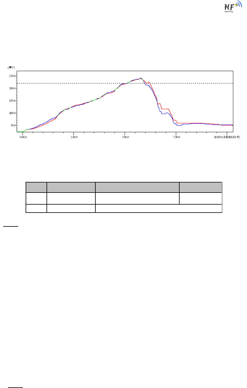
HF-LPB200 Low Power WiFi Module User Manual
Shanghai High-Flying Electronics Technology Co., Ltd
www.hi-flying.com
- 54 -
6. PACKAGE INFORMATION
6.1. Recommended Reflow Profile
Figure 38. Reflow Soldering Profile
Table 11 Reflow Soldering Parameter
Note: 1. Recommend to supply N2 for reflow oven.
2. N2 atmosphere during reflow (O2<300ppm)
6.2. Device Handling Instruction (Module IC SMT Preparation)
1. Shelf life in sealed bag: 12 months, at <30℃ and <60% relative humidity (RH)
2. After bag is opened, devices that will be re-baked required after last baked with window time
168 hours.
3. Recommend to oven bake with N2 supplied
4. Recommend end to reflow oven with N2 supplied
5. Baked required with 24 hours at 125+-5℃ before rework process for two modules, one is
new module and two is board with module
6. Recommend to store at ≦10% RH with vacuum packing
7. If SMT process needs twice reflow:
(1) Top side SMT and reflow (2) Bottom side SMT and reflow
Case 1: Wifi module mounted on top side. Need to bake when bottom side process over 168
hours window time, no need to bake within 168 hours
Case 2: Wifi module mounted on bottom side, follow normal bake rule before process
Note: Window time means from last bake end to next reflow start that has 168 hours space.
NO.
Item
Temperature (Degree)
Time(Sec)
1
Reflow Time
Time of above 220
35~55 sec
2
Peak-Temp
260 max
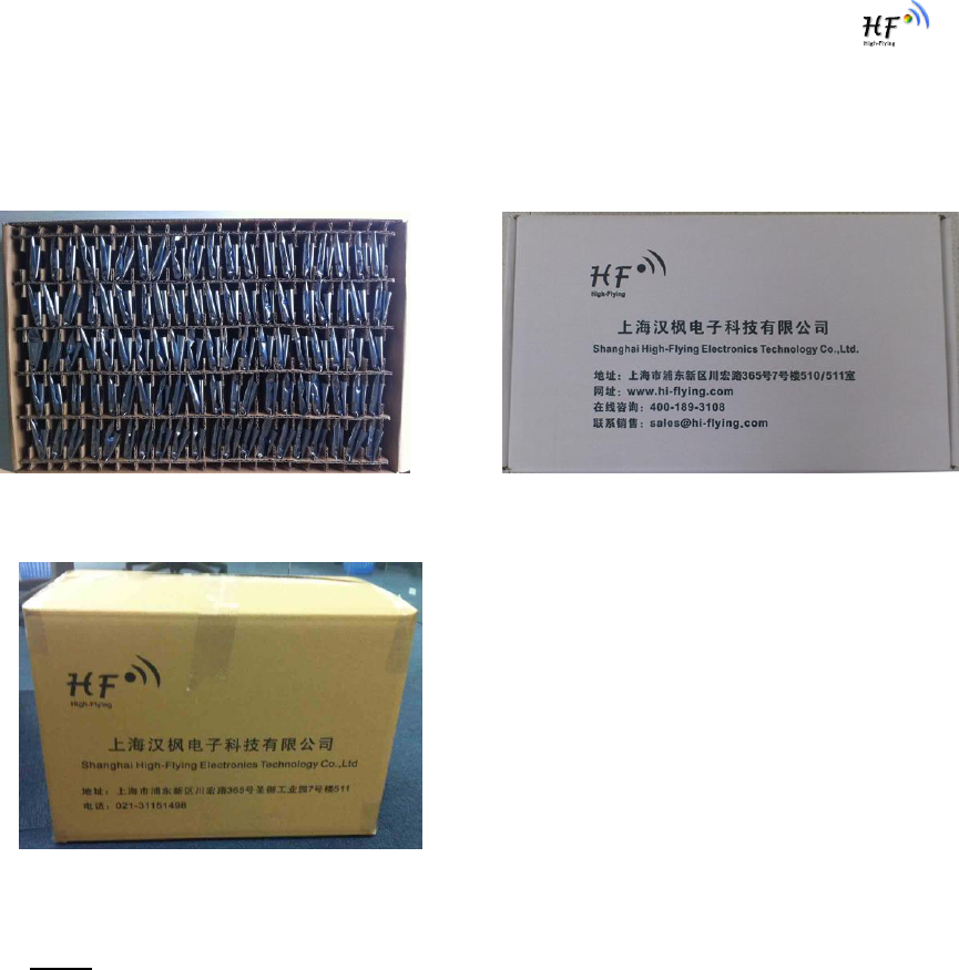
HF-LPB200 Low Power WiFi Module User Manual
Shanghai High-Flying Electronics Technology Co., Ltd
www.hi-flying.com
- 55 -
6.3. Shipping Information
TRAY BOX
Size: 420*245*34 mm Size: 422*247*72 mm (inside)
CARTON
Size: 440*260*320 mm (inside)
Figure 39. Shipping Information
Note:
1 tray = 5*20pcs = 100 pcs
1 box = 2 trays = 2 * 100 pcs = 200pcs
1 carton = 4 boxes = 4 * 200 pcs = 800pcs
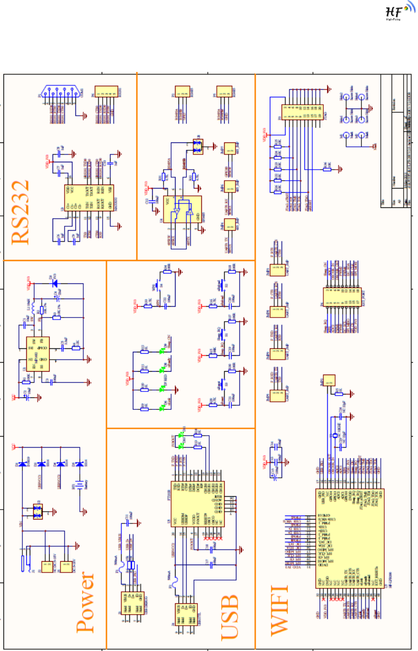
HF-LPB200 Low Power WiFi Module User Manual
Shanghai High-Flying Electronics Technology Co., Ltd
www.hi-flying.com
- 56 -
APPENDIX A: HW REFERENCE DESIGN
Detailed HF-LPB200 Evluation Board design source files, pls access High-Flying web download page
or contact with High-Flying technical support people to acquire.

HF-LPB200 Low Power WiFi Module User Manual
Shanghai High-Flying Electronics Technology Co., Ltd
www.hi-flying.com
- 57 -
APPENDIX B: CONTACT INFORMATION
------------------------------------------------------------------------------------------------------------
Address: Room.511/510, Building 7, No.365, Chuanhong Road, Pudong New Area,
Shanghai, China, 201202
Web: www.hi-flying.com
Service Online: 400-189-3108
Sales Contact: sales@hi-flying.com
-----------------------------------------------------------------------------------------------------------
For more information about High-Flying modules, applications, and solutions, please visit our web site
http://www.hi-flying.com/en/
END OF DOCUMENT
© Copyright High-Flying, May, 2011
The information disclosed herein is proprietary to High-Flying and is not to be used by or disclosed to unauthorized persons
without the written consent of High-Flying. The recipient of this document shall respect the security status of the information.
The master of this document is stored on an electronic database and is “write-protected” and may be altered only by
authorized persons at High-Flying. Viewing of the master document electronically on electronic database ensures access to
the current issue. Any other copies must be regarded as uncontrolled copies.
FCC STATEMENT
1. This device complies with Part 15 of the FCC Rules. Operation is subject to the following two
conditions:
(1) This device may not cause harmful interference.
(2) This device must accept any interference received, including interference that may cause
undesired operation.
2. Changes or modifications not expressly approved by the party responsible for compliance could
void the user's authority to operate the equipment.
NOTE: This equipment has been tested and found to comply with the limits for a Class B digital
device, pursuant to Part 15 of the FCC Rules. These limits are designed to provide reasonable
protection against harmful interference in a residential installation.
This equipment generates uses and can radiate radio frequency energy and, if not installed and
used in accordance with the instructions, may cause harmful interference to radio communications.
However, there is no guarantee that interference will not occur in a particular installation. If this
equipment does cause harmful interference to radio or television reception, which can be
determined by turning the equipment off and on, the user is encouraged to try to correct the
interference by one or more of the following measures:
Reorient or relocate the receiving antenna.
Increase the separation between the equipment and receiver.
Connect the equipment into an outlet on a circuit different from that to which the receiver is
connected.
Consult the dealer or an experienced radio/TV technician for help.
FCC Radiation Exposure Statement
This equipment complies with FCC radiation exposure limits set forth for an uncontrolled
environment. This equipment should be installed and operated with minimum distance 20cm
between the radiator & your body