High Flying Electronics Technology HF-LPB300-1 Wi-Fi Module User Manual
High-Flying Electronics Technology Co., Ltd. Wi-Fi Module
UserManual.wiki
>
High Flying Electronics Technology
>
HF LPB300 1 User Manual
User Manual
Navigation menu
Upload a User Manual
Namespaces
Wiki Guide
HTML
PDF
Info
Views
User Manual
Discussion / Help
Navigation

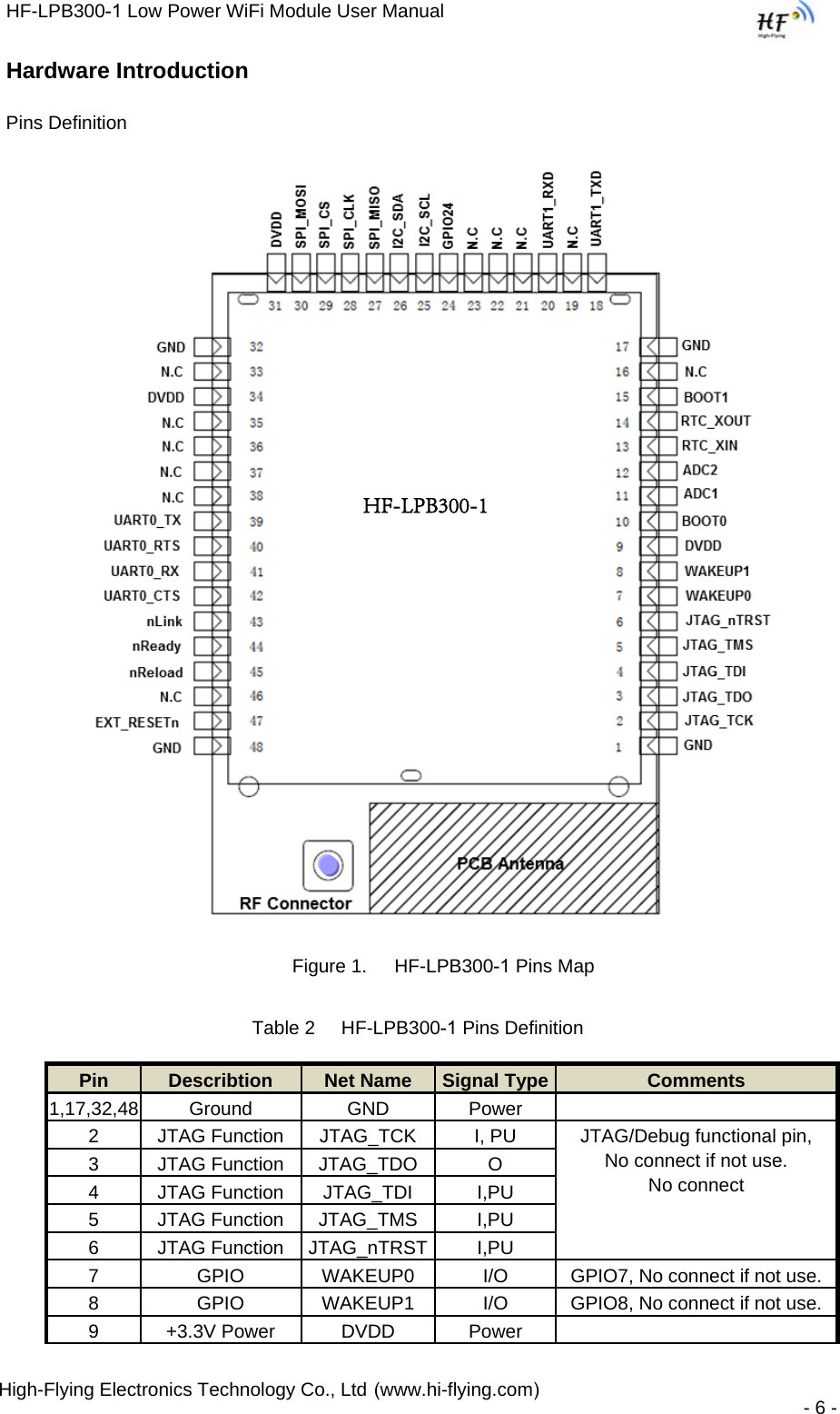
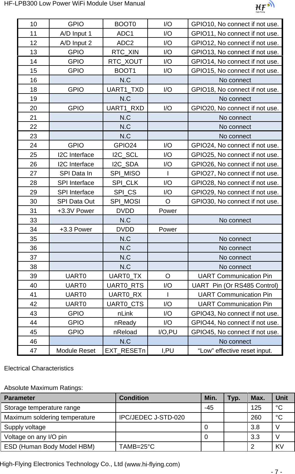
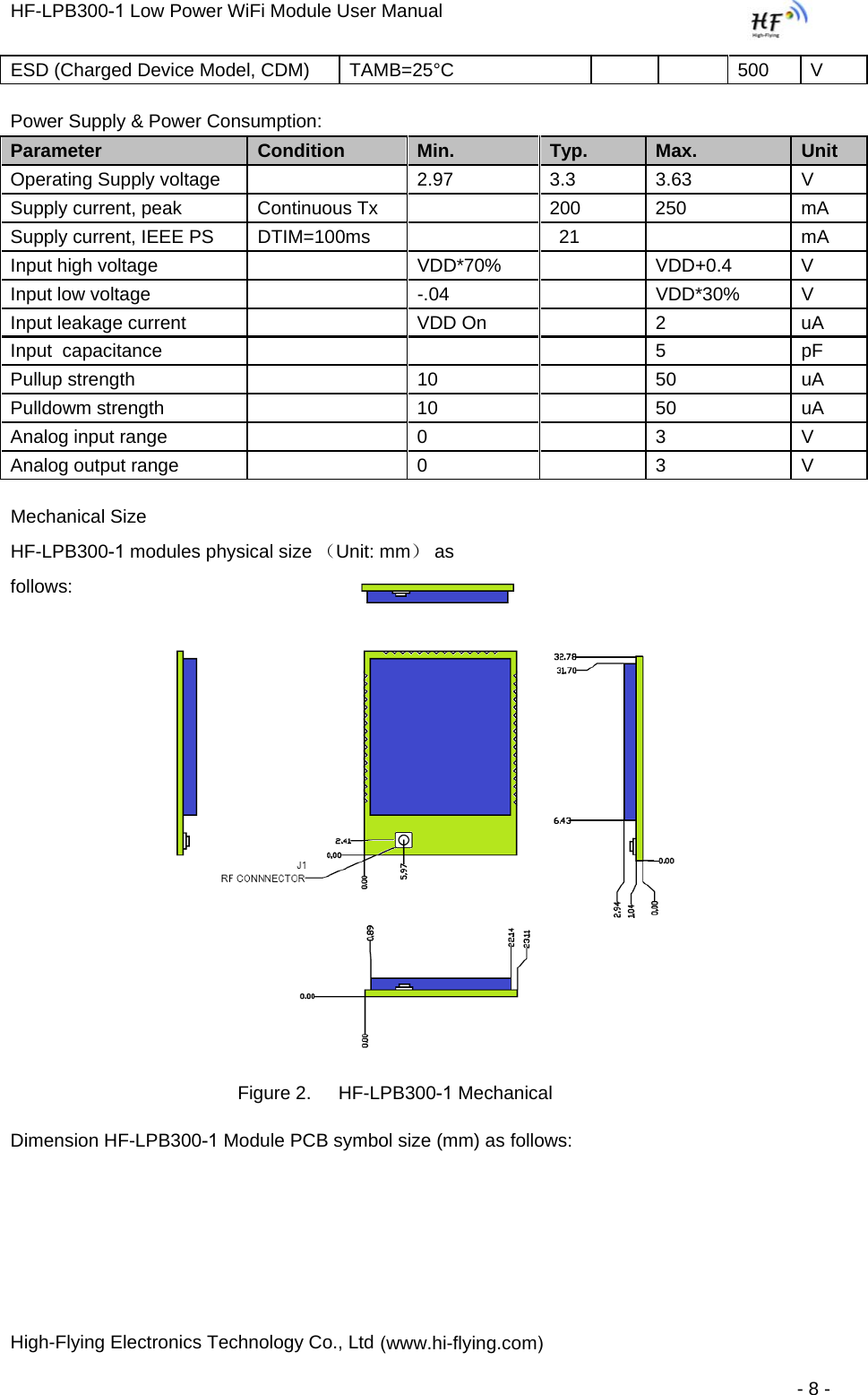
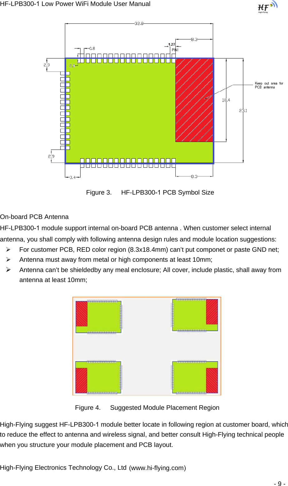
![HF-LPB300-1 Low Power WiFi Module User Manual High-Flying Electronics Technology Co., Ltd (www.hi-flying.com) - 5 - Device Paremeters Table 1 HF-LPB300-1 Module Technical Specifications Class Item Parameters Wireless Parameters Certification FCCWireless standard 802.11 b/g/n-HT20 Frequency range 2.412GHz-2.462GHz RF Output Power(Peak) 802.11b:20.05 dBm (@1Mbps) 802.11g: 18.89dBm (@6Mbps ) 802.11n-HT20: 17.88dBm (@HT20, MCS0) Antenna On-board PCB antenna Hardware Parameters Data Interface UART SPI, PWM, GPIO… Others: USB, ADC, RTC… Operating Voltage 2.97V~3.63V Operating Current Peak [Continuous TX]: ~240mA Normal [WiFi ON/OFF, DTIM=100ms]: AP Associate: ~21mA; No-AP Associate:~26mA Wakeup-on-Wireless Mode: ~10mA; Deep Sleep: <100uA Operating Temp. -40℃- 85℃ Storage Temp. -45℃- 125℃ Dimensions and Size 23.1mm×32.8mm×2.7mm Software Parameters Network Type STA /AP/STA+AP/Wi-Fi Direct Security Mechanisms WEP/WPA-PSK/WPA2-PSK Encryption WEP64/WEP128/TKIP/AESUpdate Firmware Local Wireless (OTA), Remote Network Protocol IPv4,TCP/UDP/FTP/HTTP,FTTPS,TLS,mDNS User Configuration AT+instruction set, Web page/ Android/ iOS Smart Link APP tools Key Application Remote equipment monitoringSmart Home/EnergyIndustrial sensors and controlsHome automationMedical/Healthcare devices](https://usermanual.wiki/High-Flying-Electronics-Technology/HF-LPB300-1/User-Guide-3846732-Page-5.png)