High Flying Electronics Technology HF-LPT100 Embedded WiFi Module User Manual GPON SFU System Design
High-Flying Electronics Technology Co.,Ltd Embedded WiFi Module GPON SFU System Design
UserManual.wiki
>
High Flying Electronics Technology
>
HF LPT100 User Manual
Manual
Navigation menu
Upload a User Manual
Namespaces
Wiki Guide
HTML
PDF
Info
Views
User Manual
Discussion / Help
Navigation
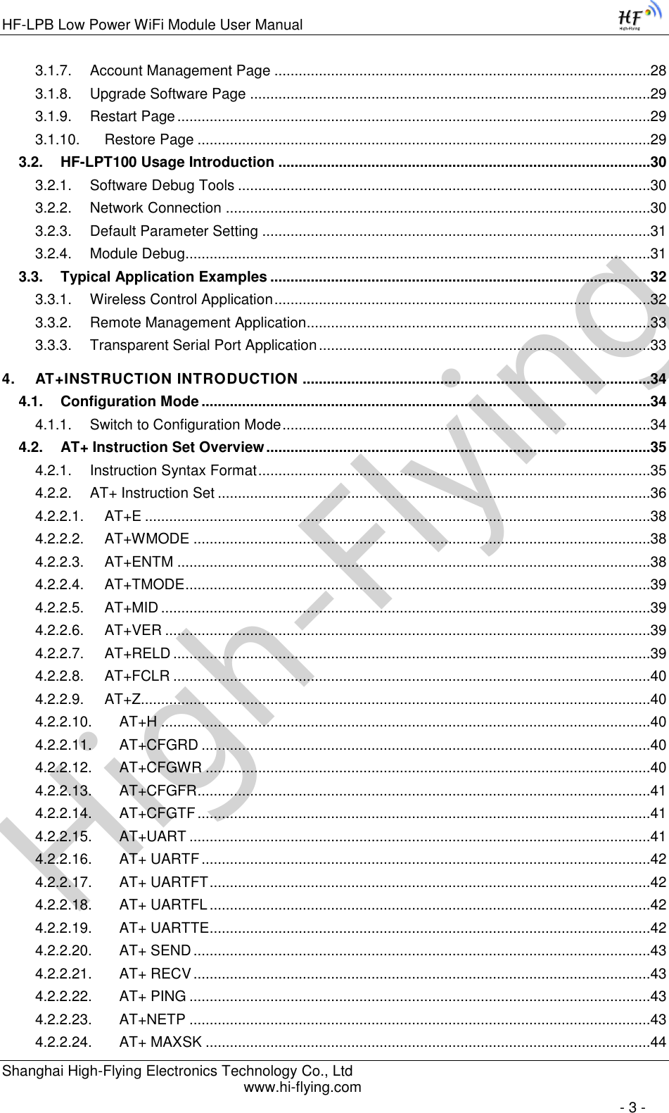
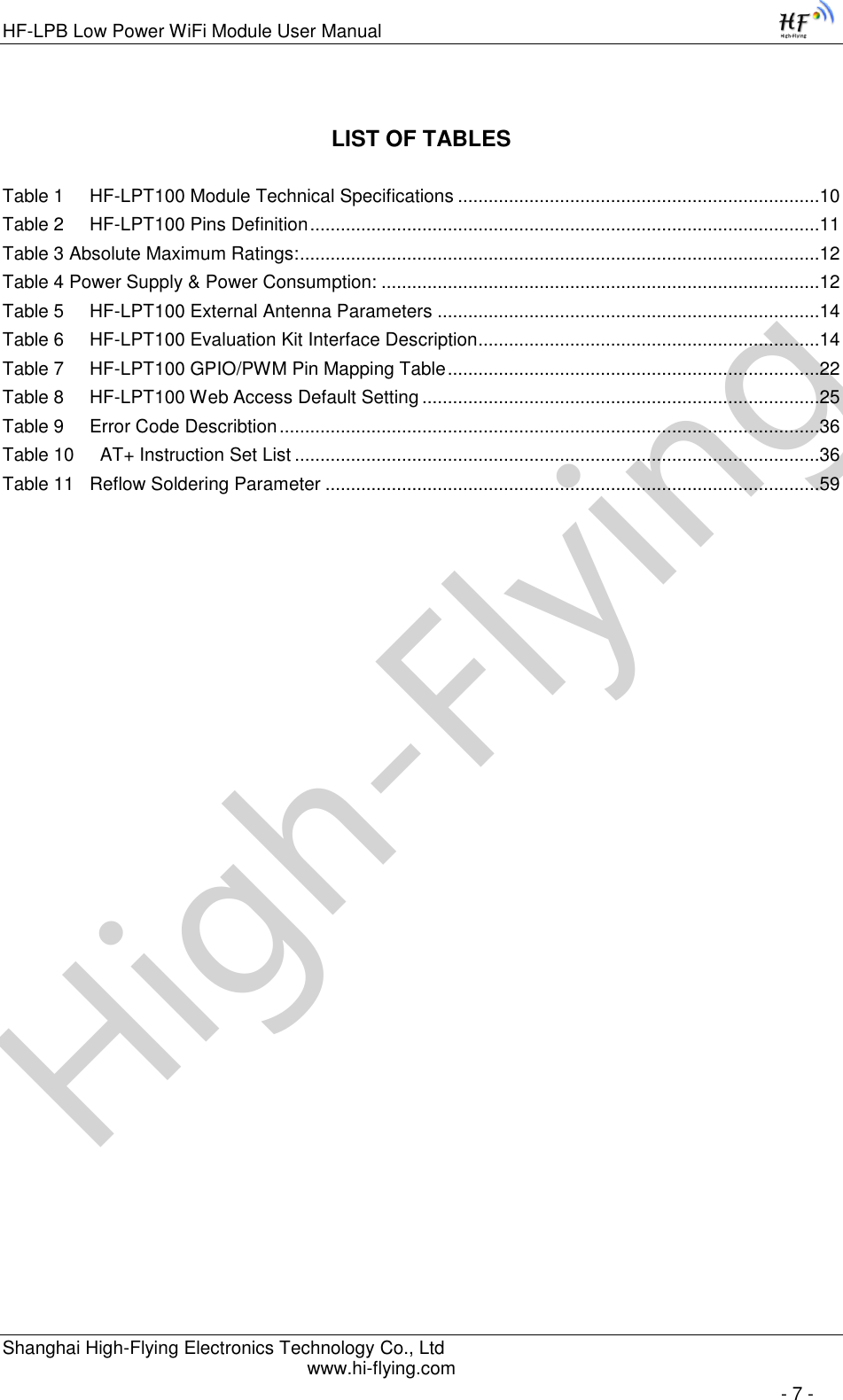
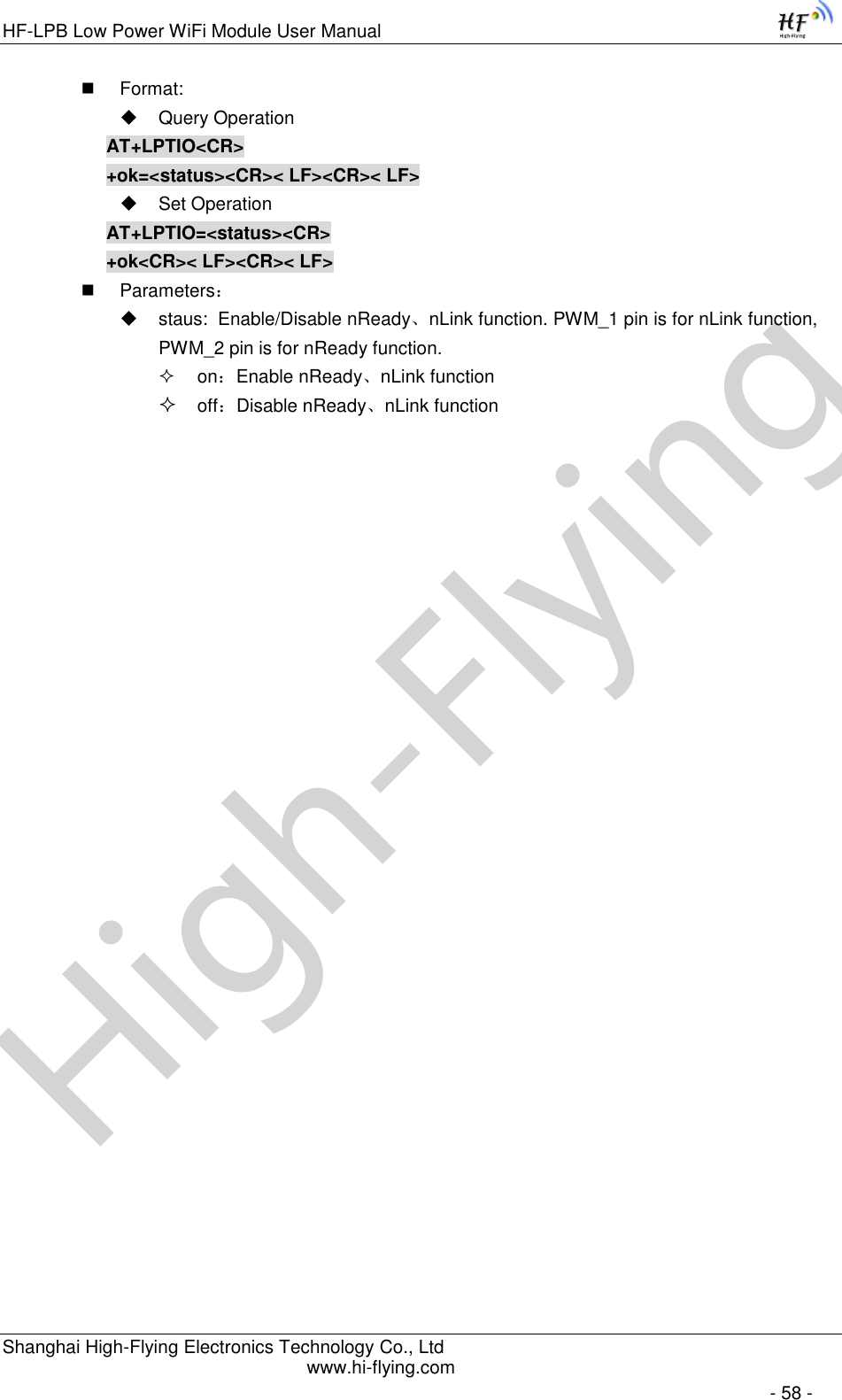
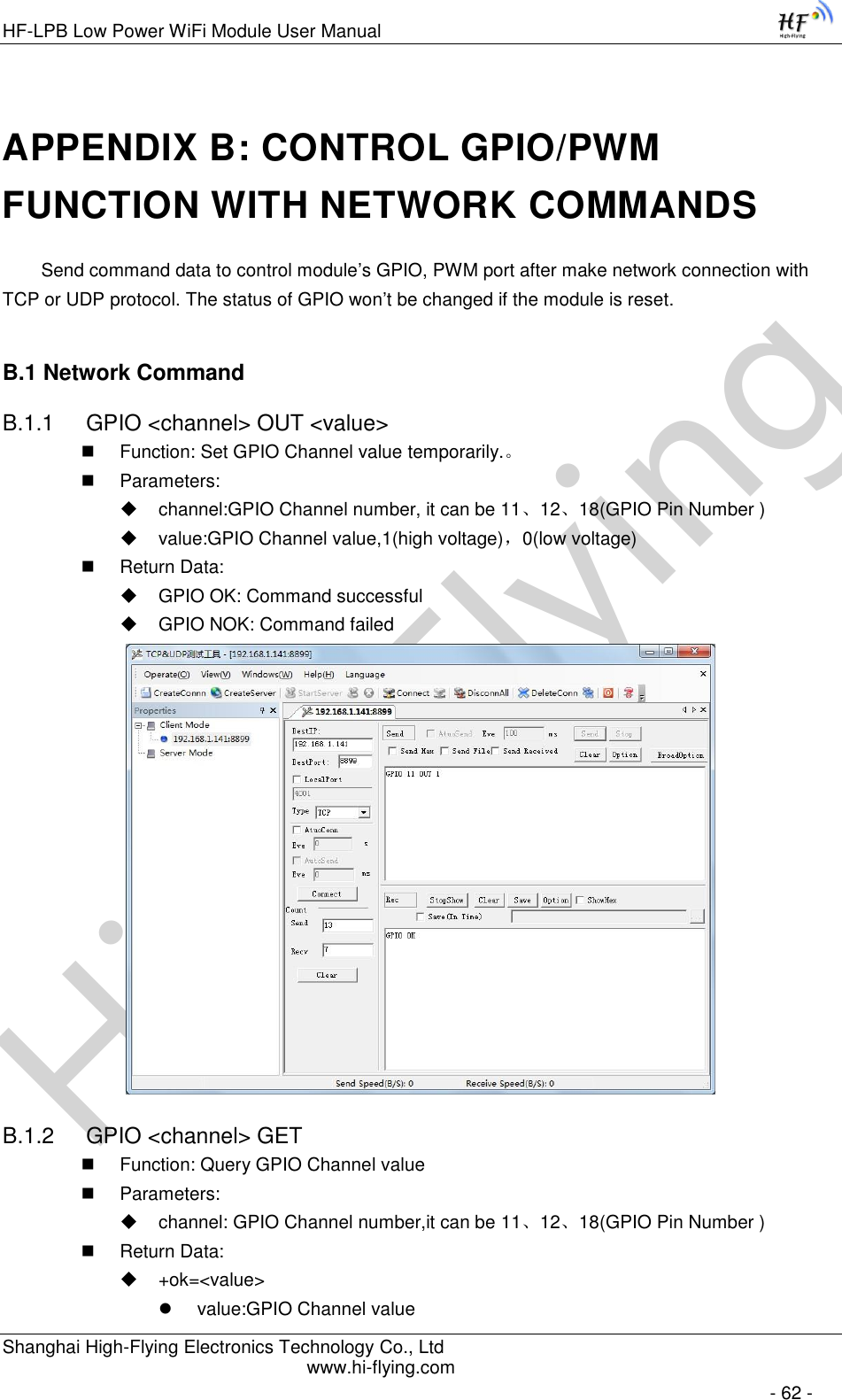
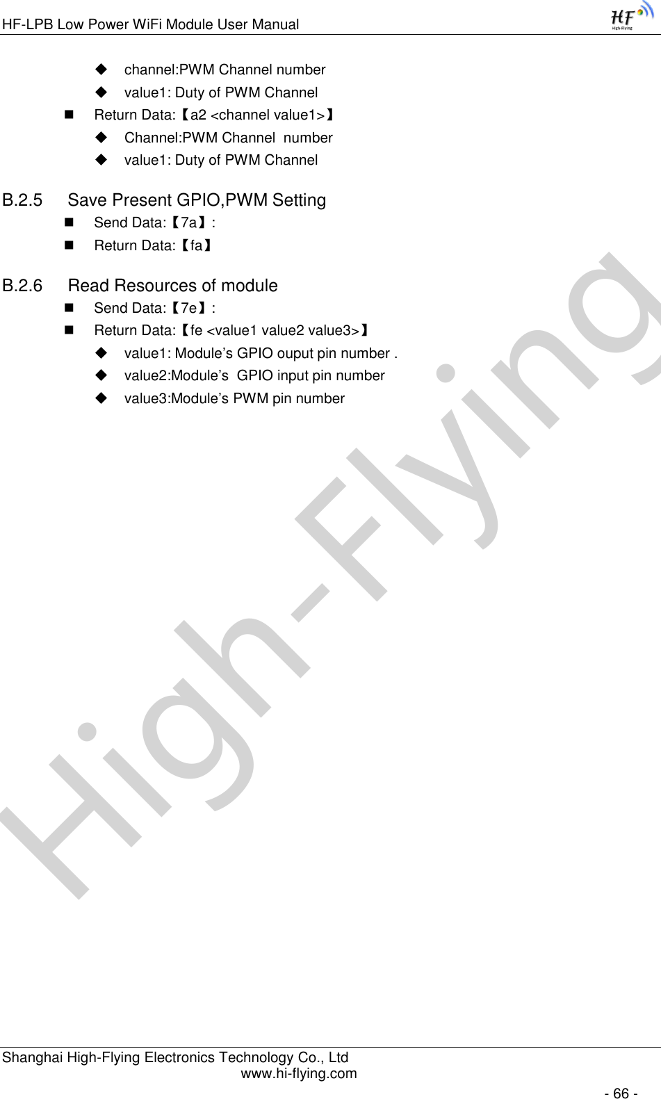
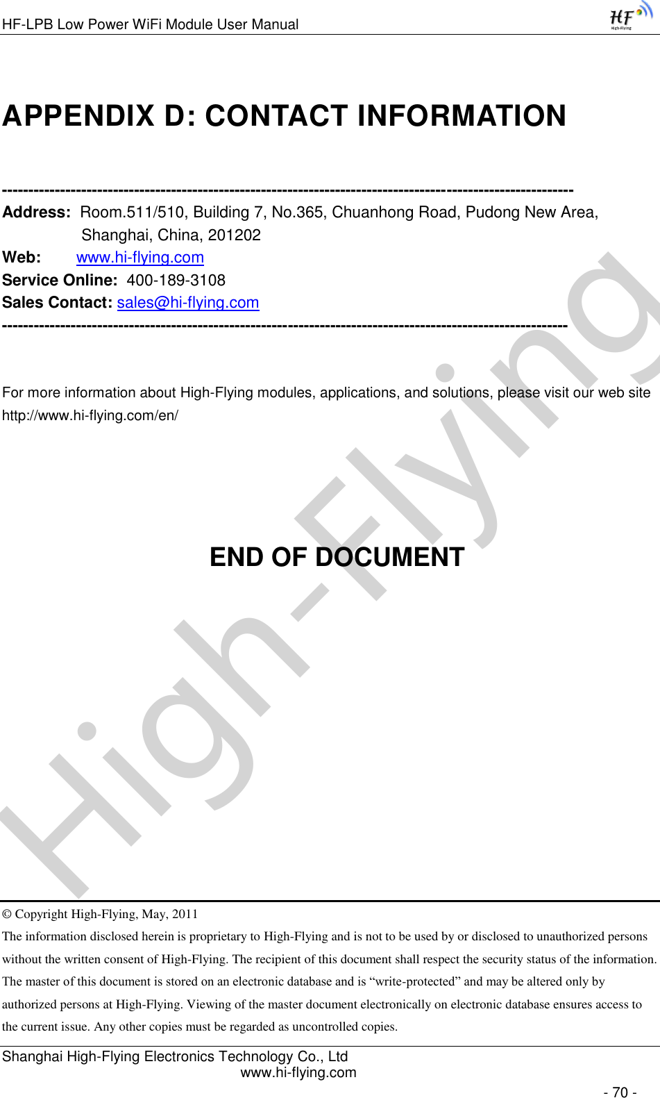
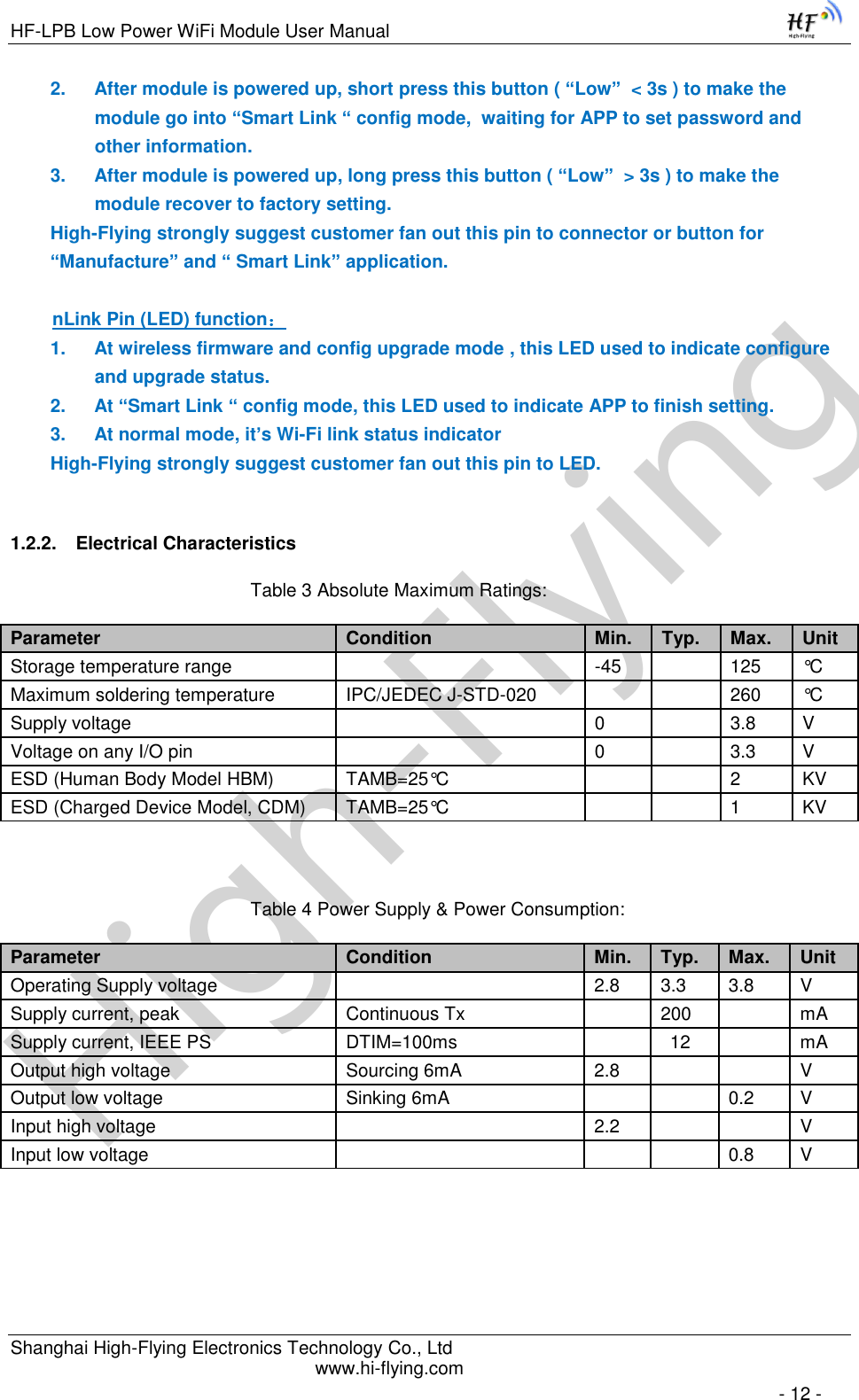
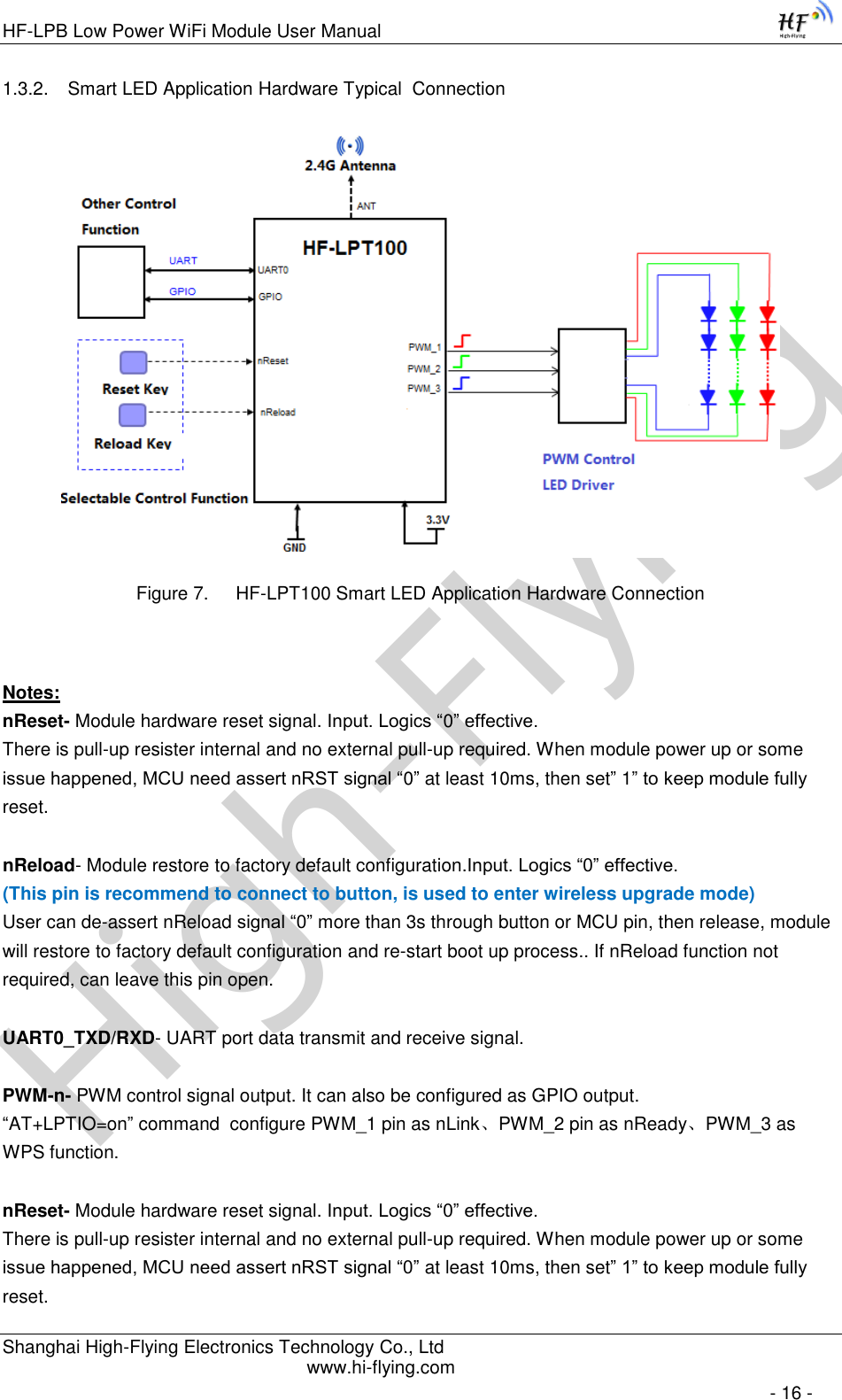
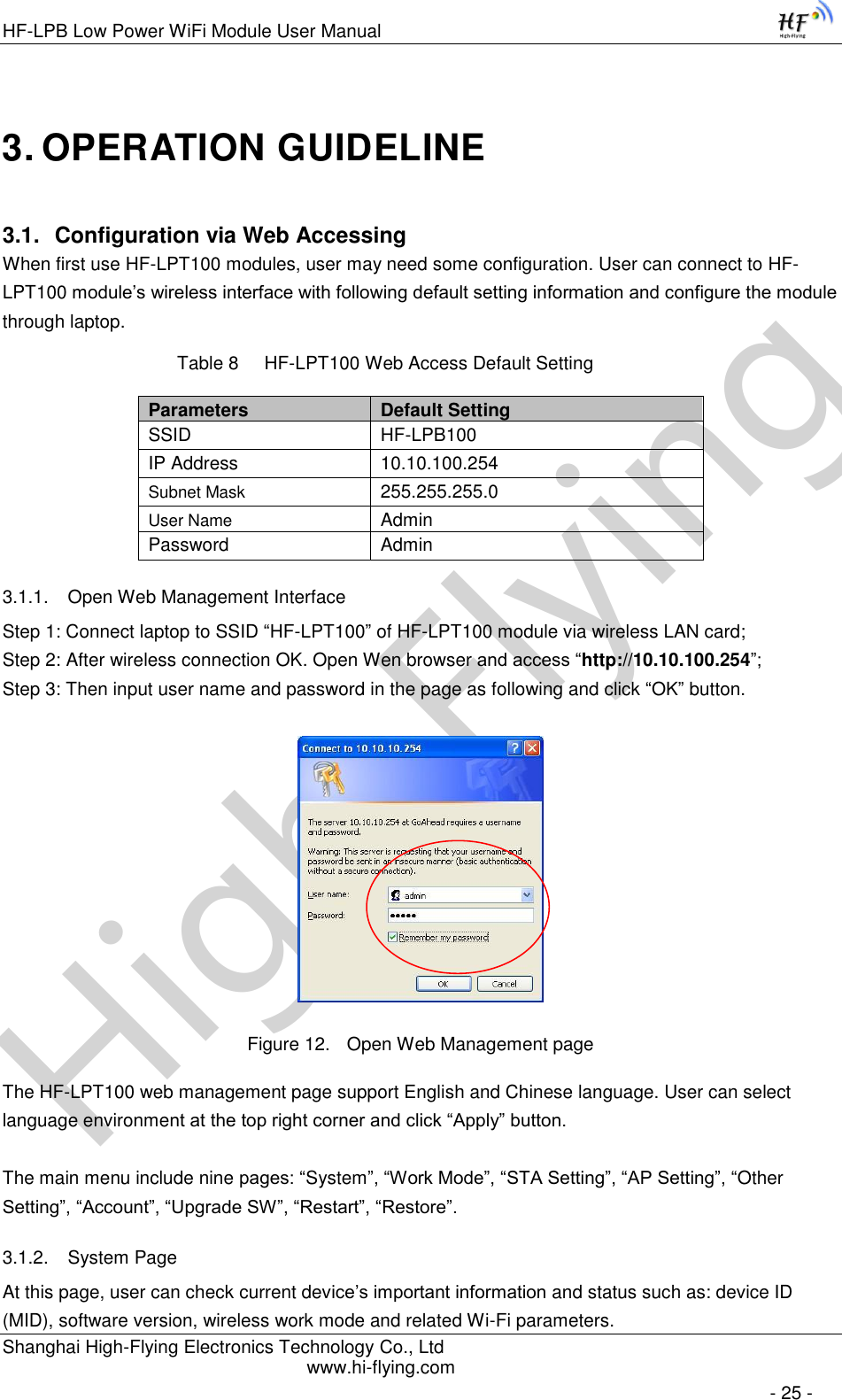
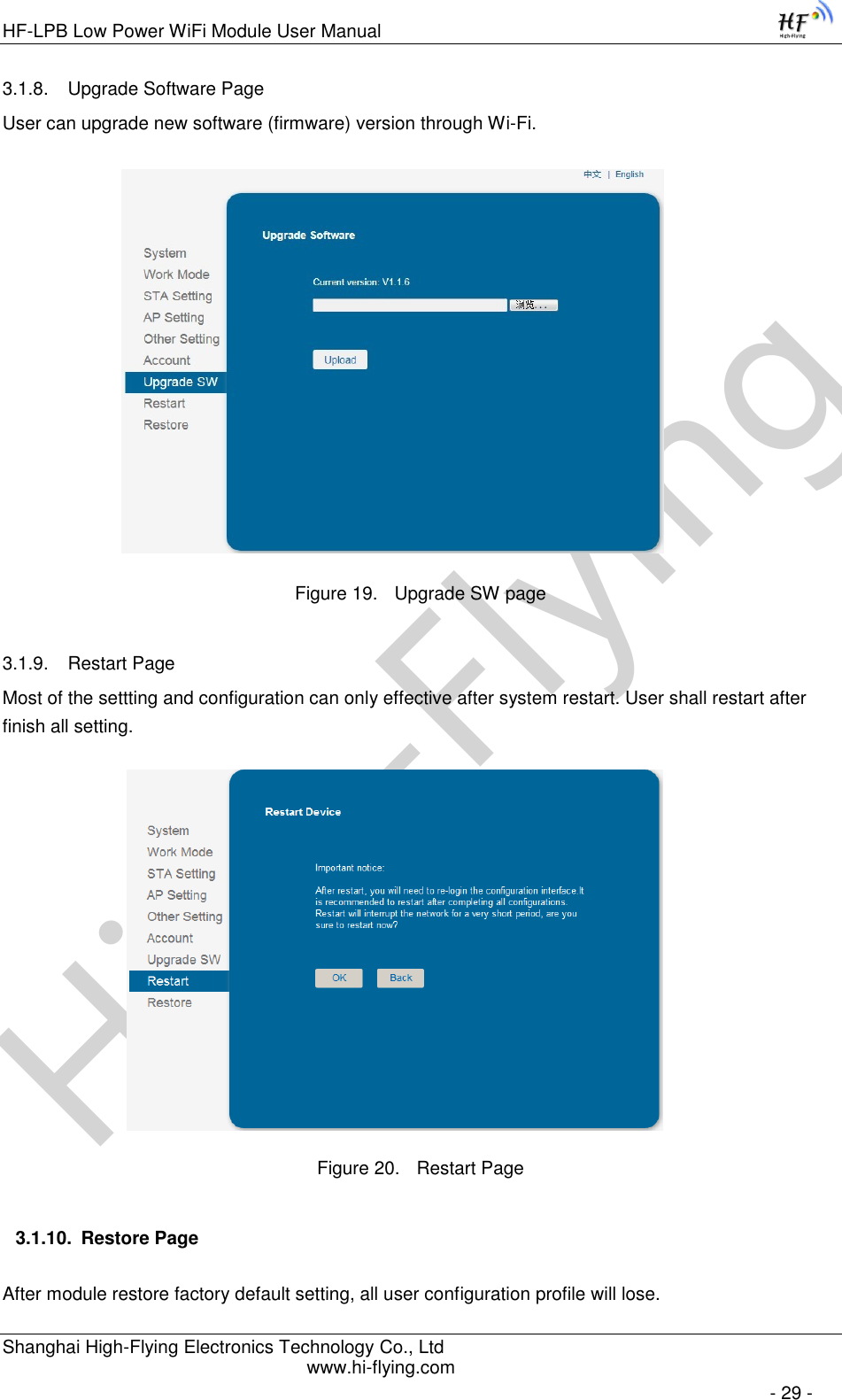
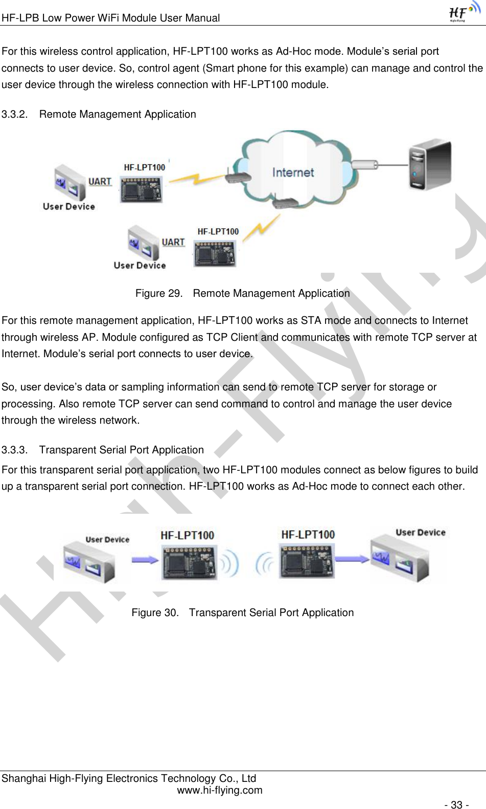
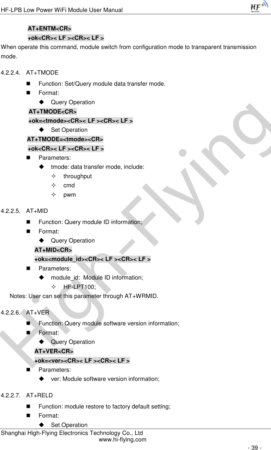
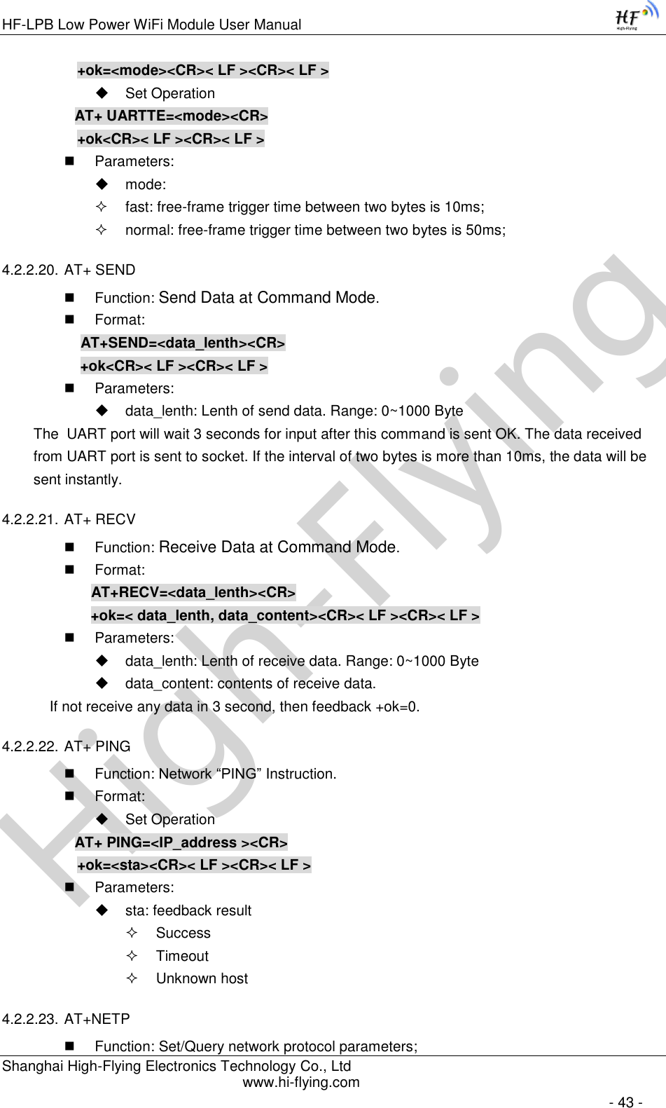
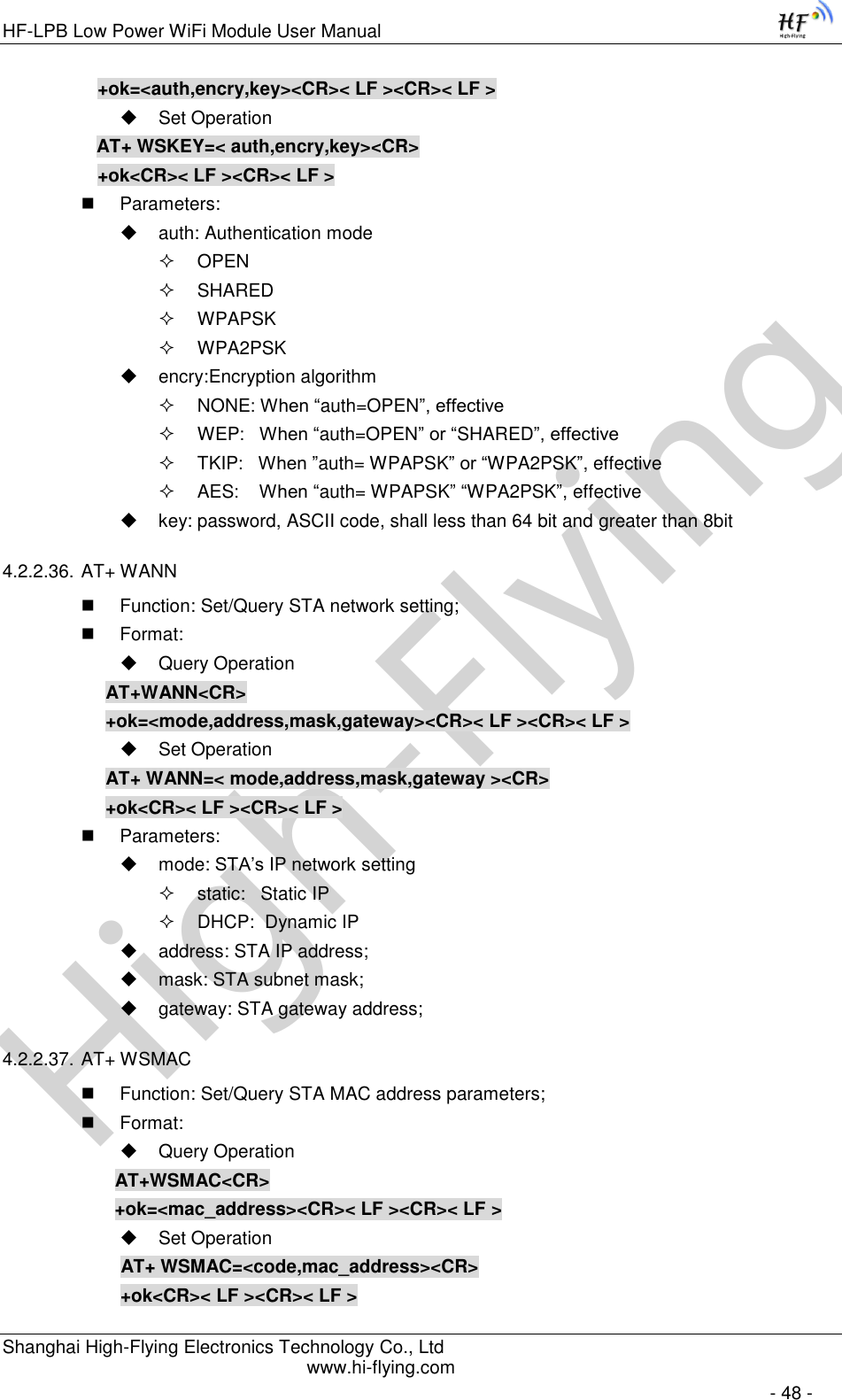
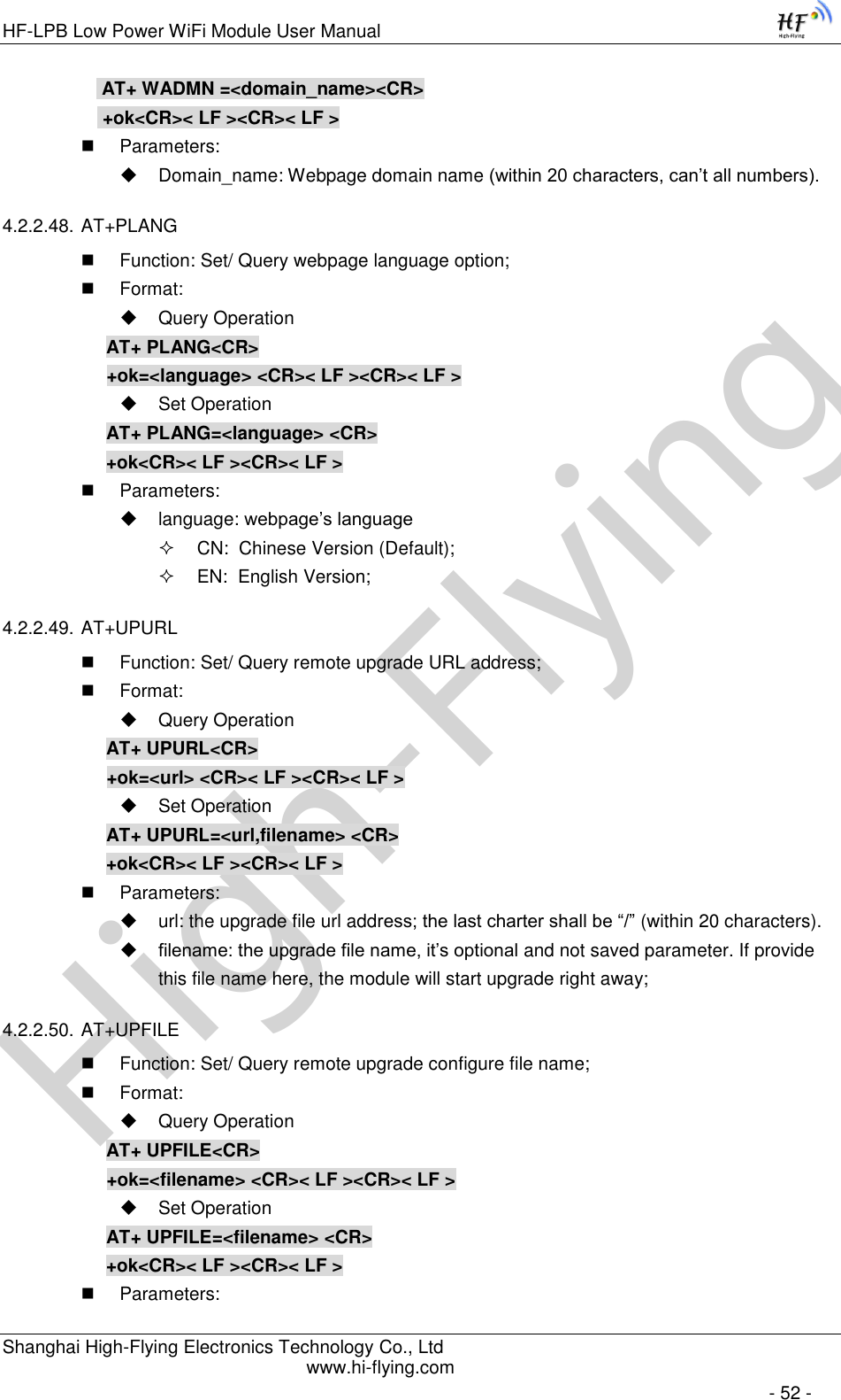
![High-FlyingHF-LPB Low Power WiFi Module User Manual Shanghai High-Flying Electronics Technology Co., Ltd www.hi-flying.com - 10 - 1.1.2 Device Paremeters Table 1 HF-LPT100 Module Technical Specifications Class Item Parameters Wireless Parameters Certification FCC/CE Wireless standard 802.11 b/g/n Frequency range 2.412GHz-2.484GHz Transmit Power 802.11b: +16 +/-2dBm (@11Mbps) 802.11g: +14 +/-2dBm (@54Mbps) 802.11n: +13 +/-2dBm (@HT20, MCS7) Receiver Sensitivity 802.11b: -93 dBm (@11Mbps ,CCK) 802.11g: -85 dBm (@54Mbps, OFDM) 802.11n: -82 dBm (@HT20, MCS7) Antenna Option External:I-PEX Connector External:Pad connector Hardware Parameters Data Interface UART PWM, GPIO Operating Voltage 2.8~3.6V Operating Current Peak [Continuous TX]: ~200mA Normal [WiFi ON/OFF, DTIM=100ms]: Average. ~12mA, Peak: 200mA Standby [WiFi Shutdown]: <200uA Power Down Switch: <10uA Operating Temp. -40℃- 85℃ Storage Temp. -45℃- 125℃ Dimensions and Size 22mm x 13.5mm x 6mm External Interface 1x10, 2mm DIP Software Parameters Network Type STA /AP/STA+AP Security Mechanisms WEP/WPA-PSK/WPA2-PSK Encryption WEP64/WEP128/TKIP/AES Update Firmware Local Wireless, Remote Customization Web Page Upgrade Support SDK for application develop Network Protocol IPv4, IPv6,TCP/UDP/FTP/HTTP User Configuration AT+instruction set. Android/ iOS Smart Link APP tools 1.1.3 Key Application Remote equipment monitoring Asset tracking and telemetry Security Industrial sensors and controls Home automation Medical devices](https://usermanual.wiki/High-Flying-Electronics-Technology/HF-LPT100/User-Guide-2151877-Page-10.png)
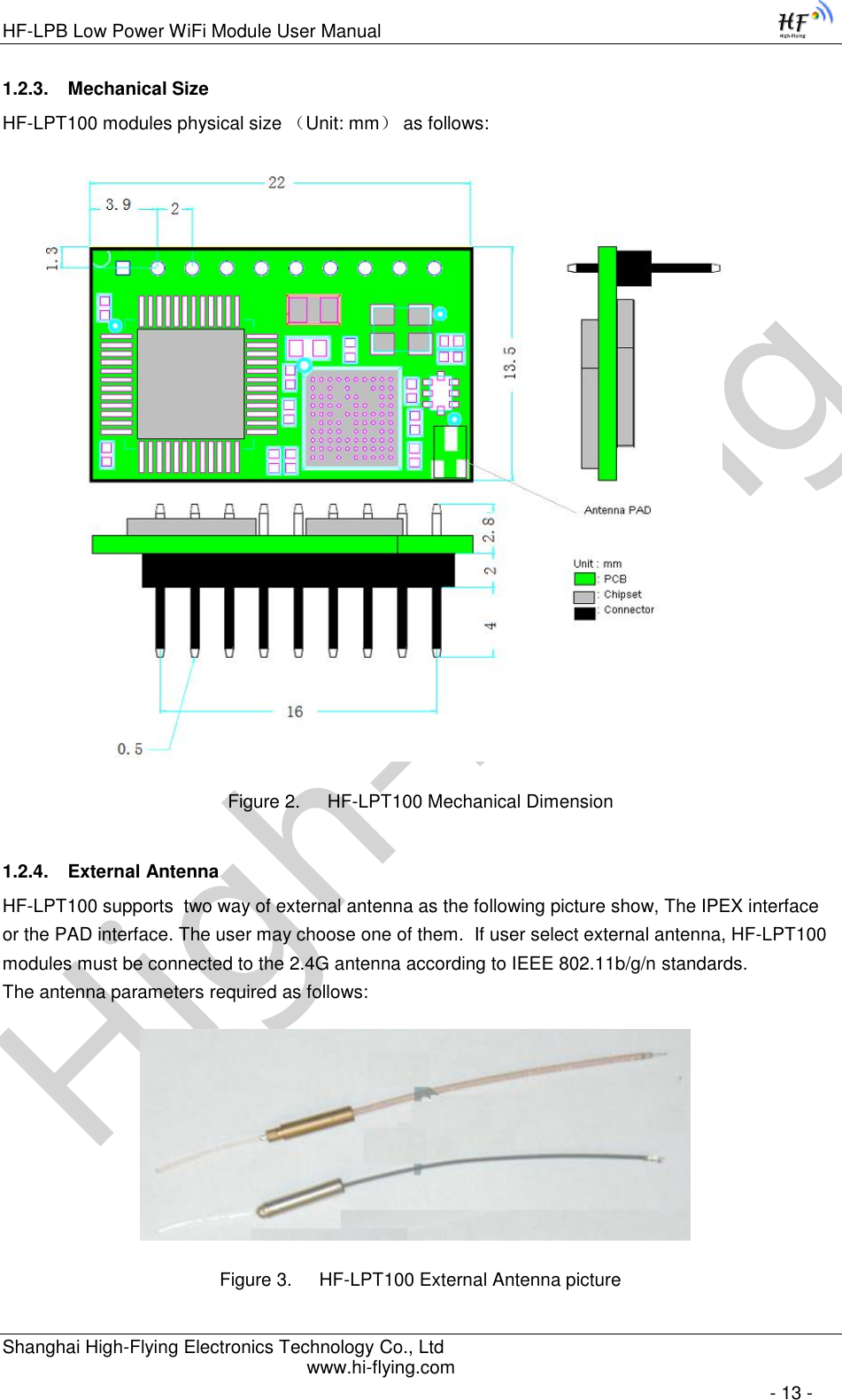
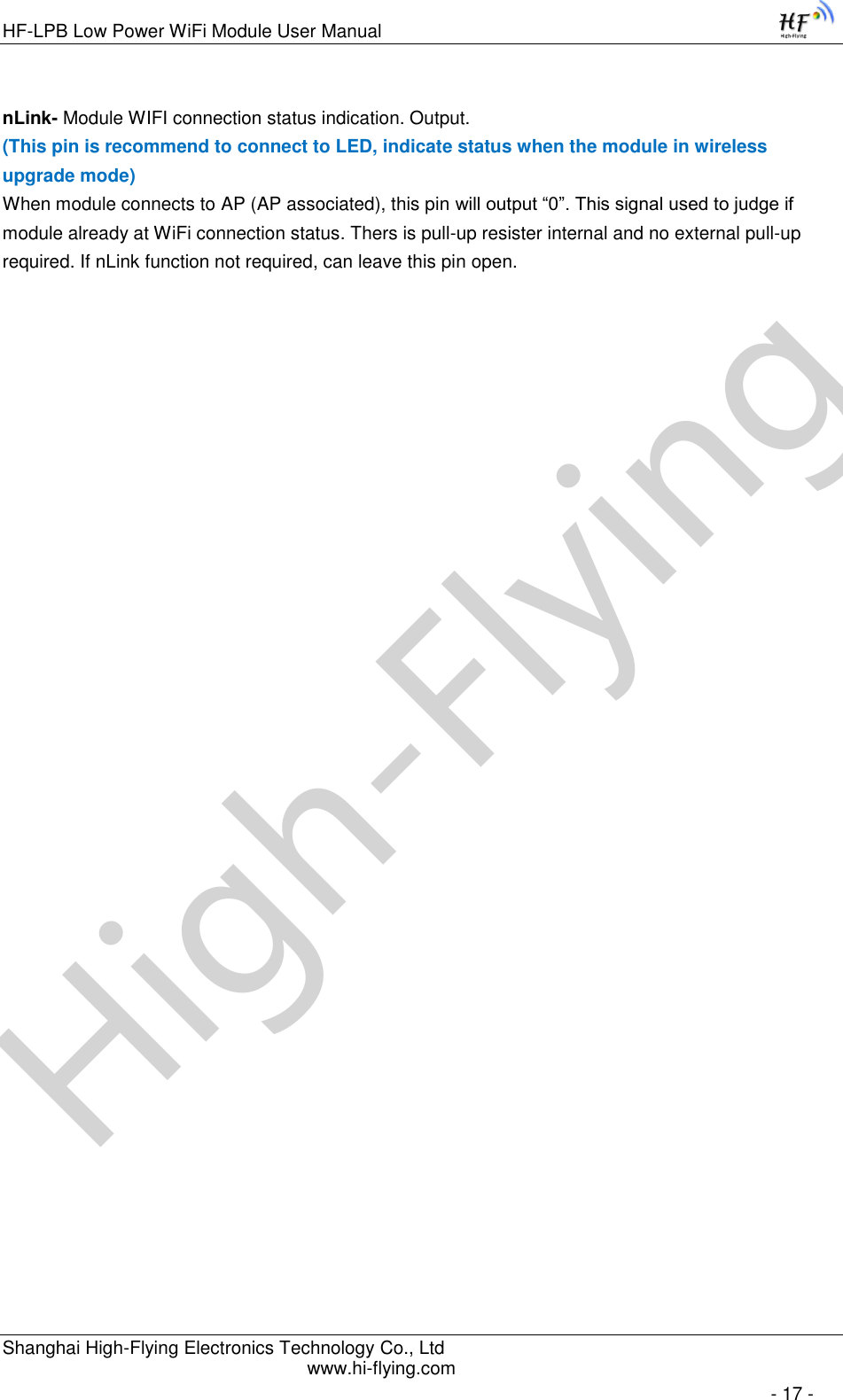
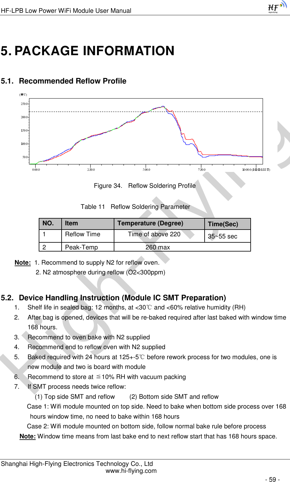
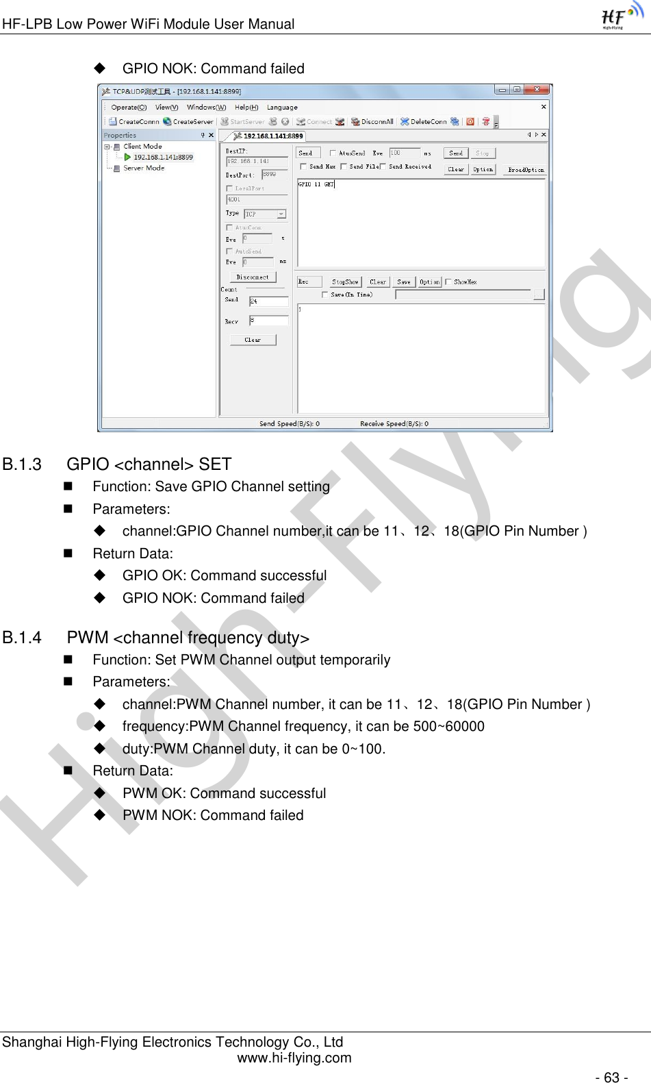
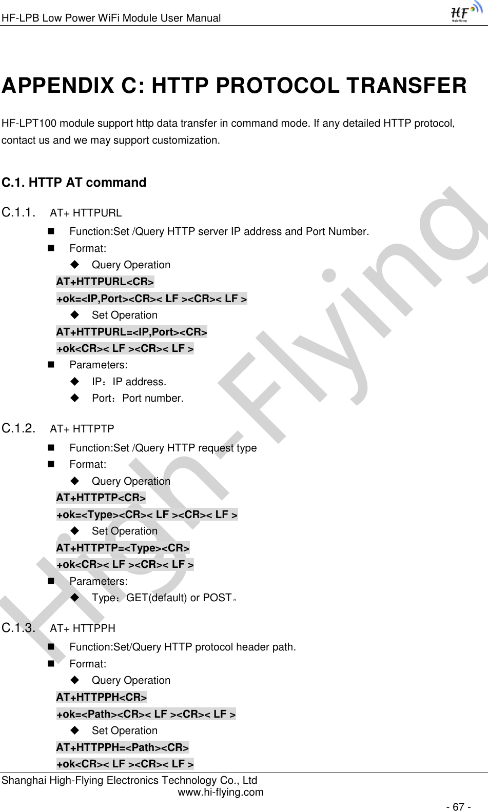
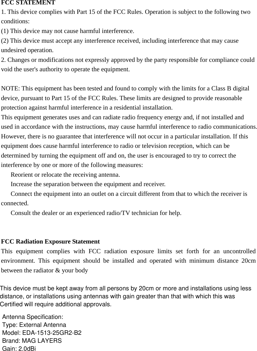
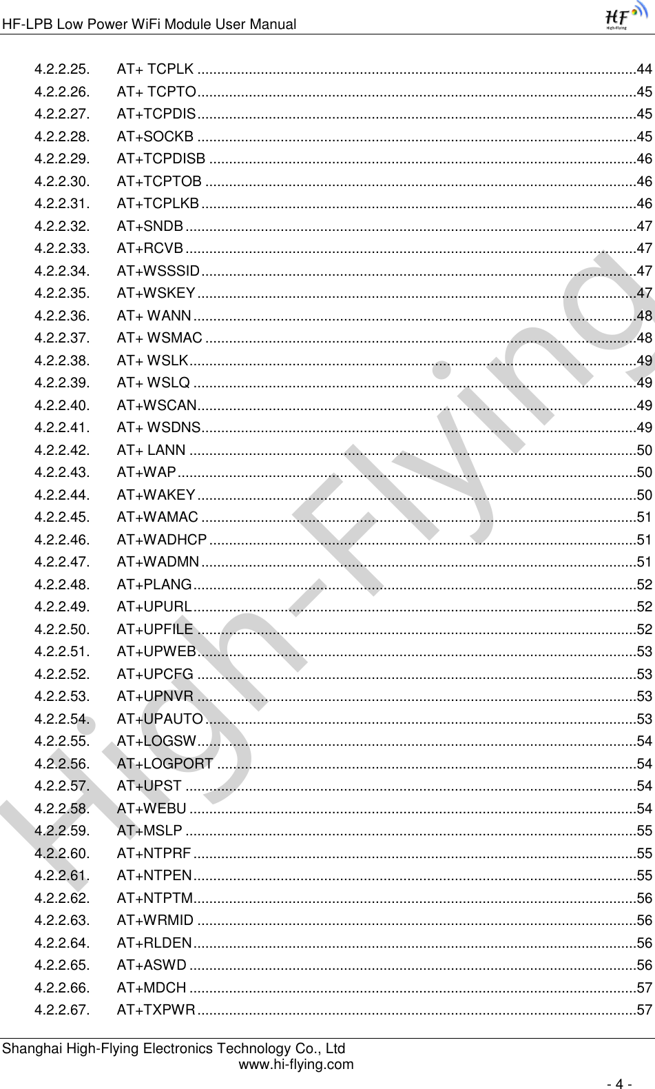
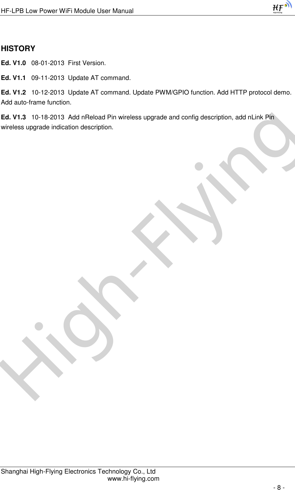
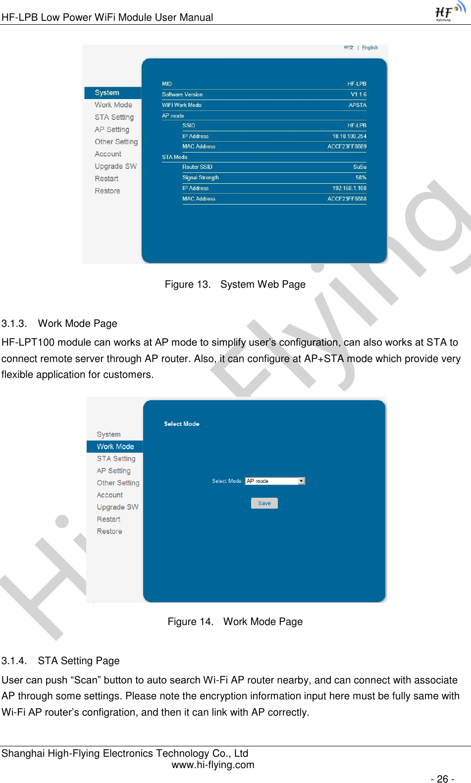
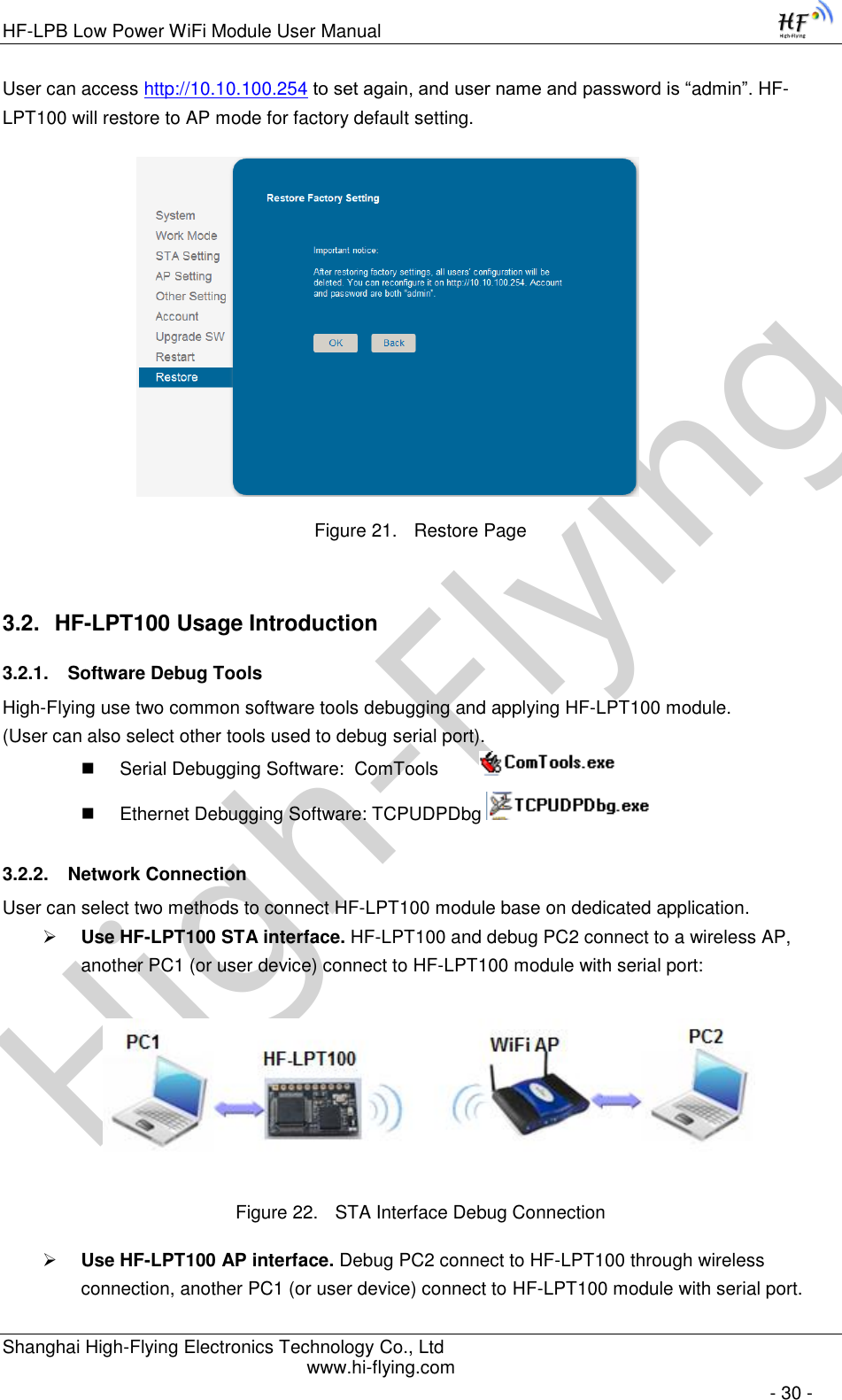
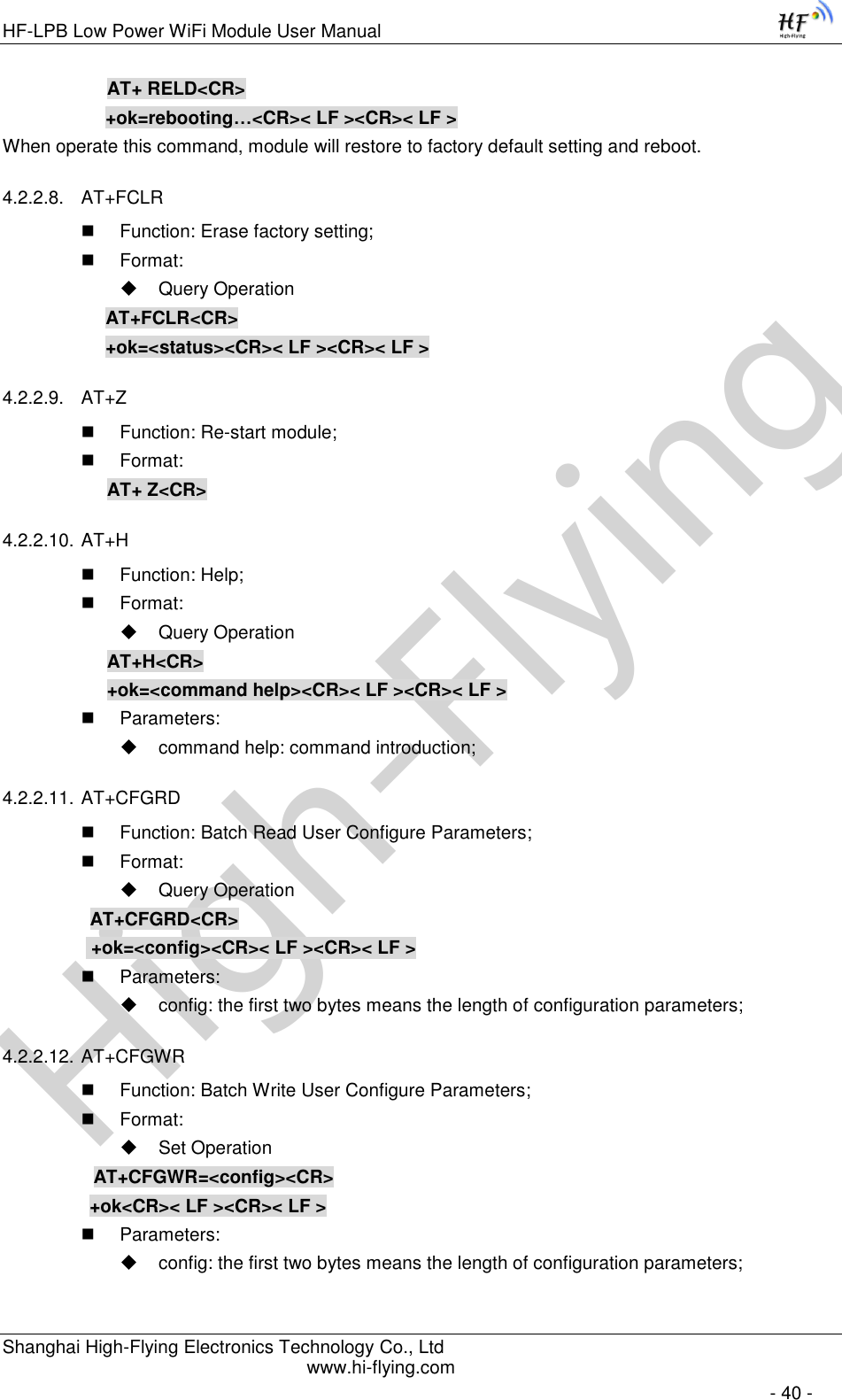
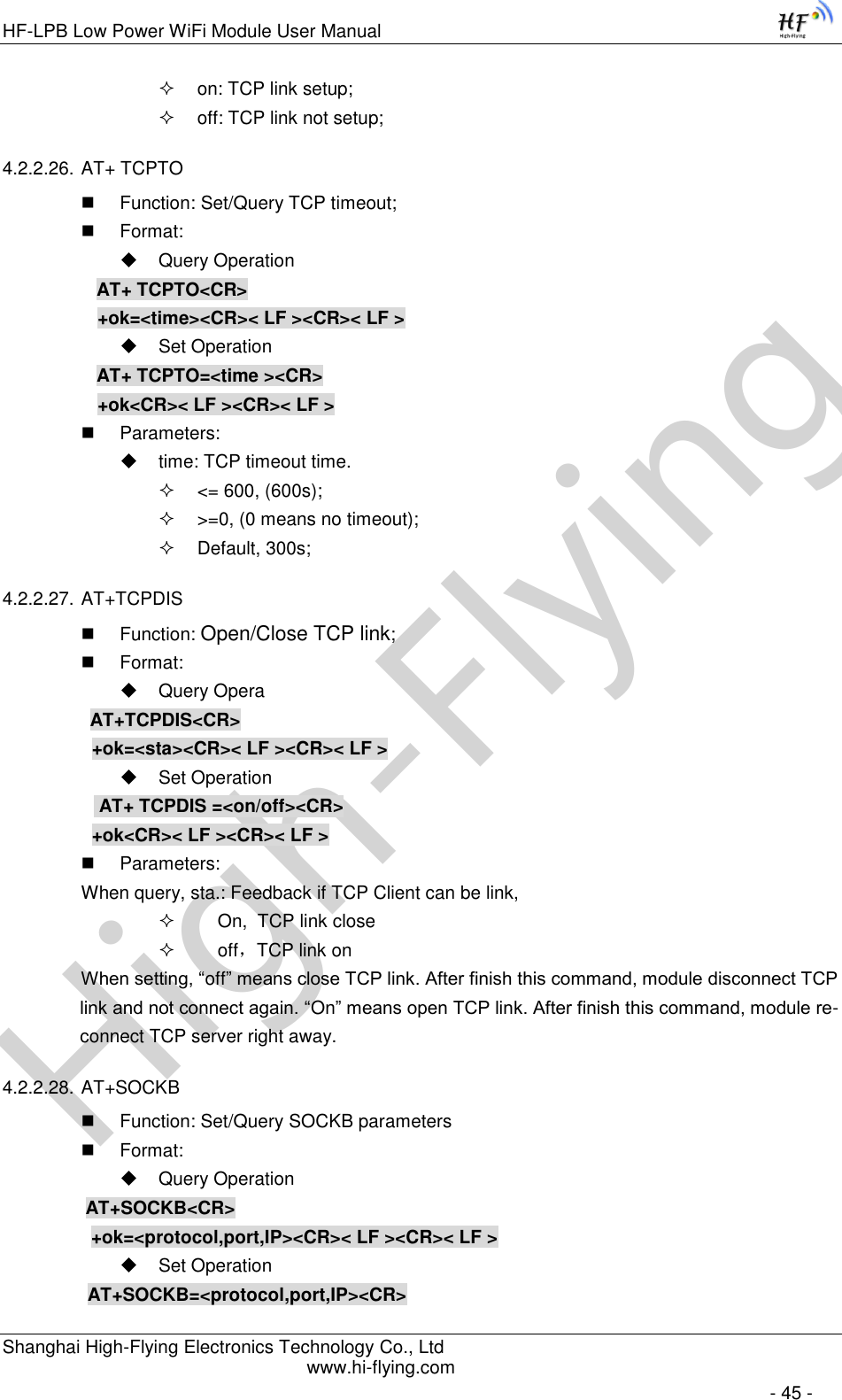
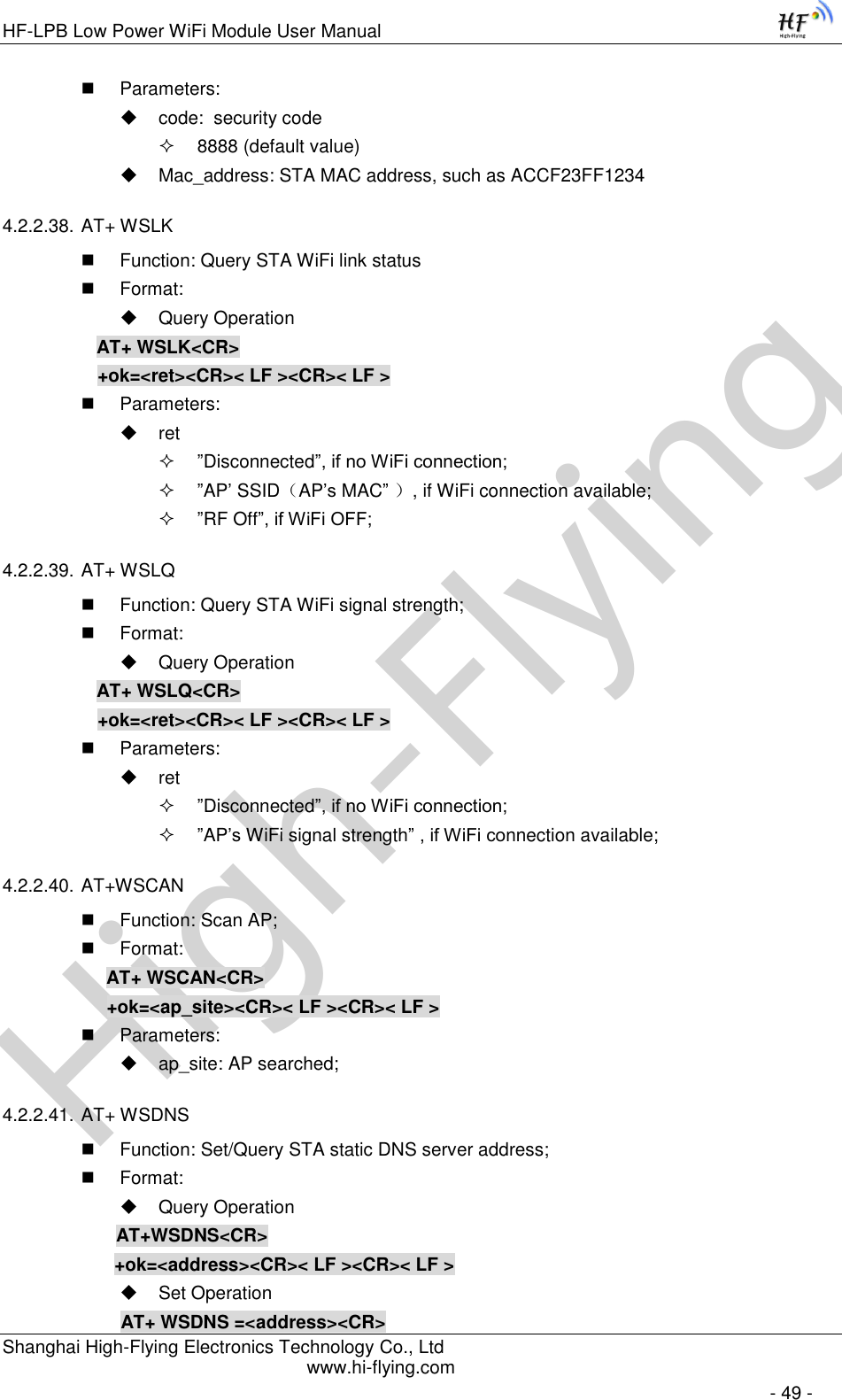
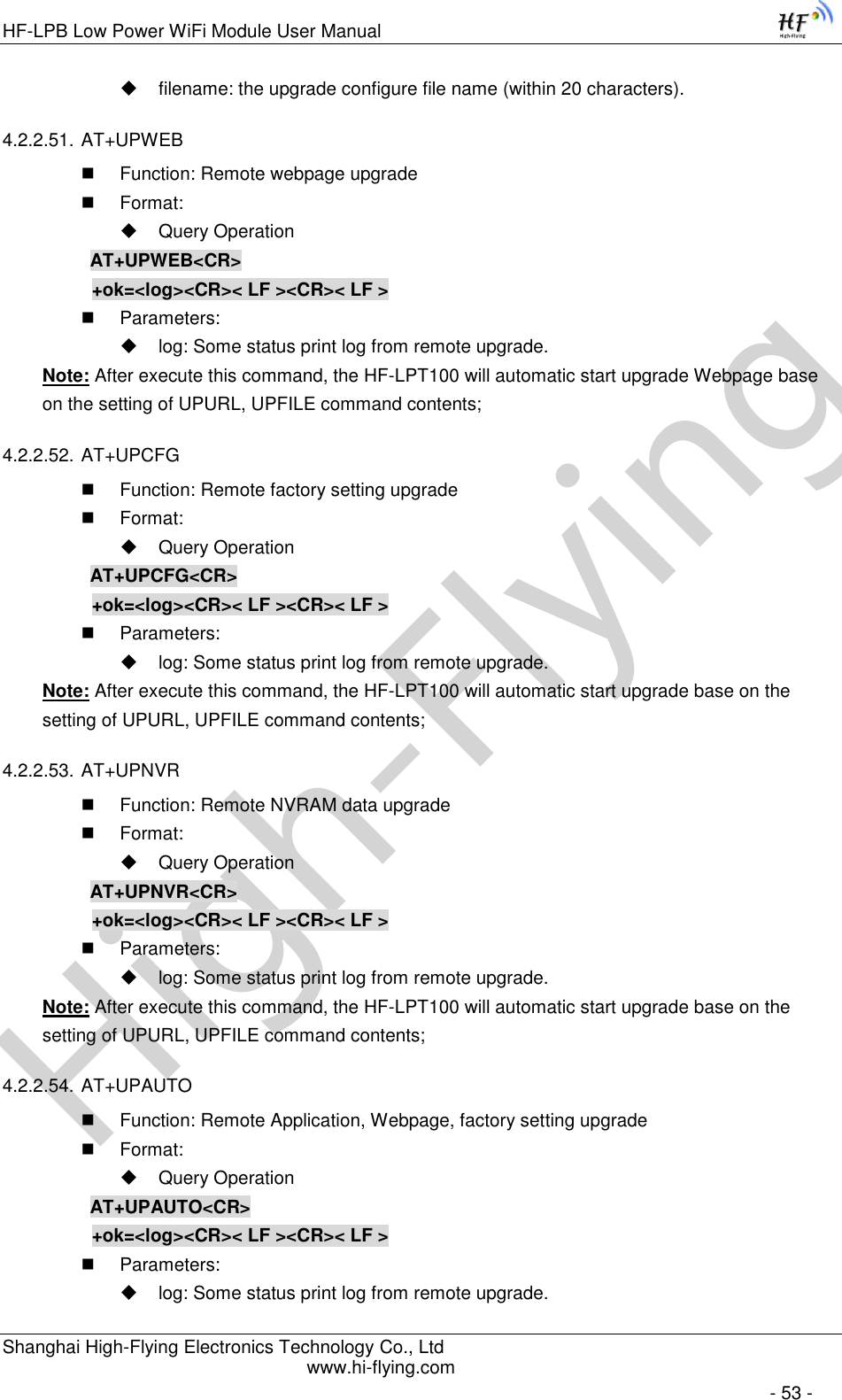
![High-FlyingHF-LPB Low Power WiFi Module User Manual Shanghai High-Flying Electronics Technology Co., Ltd www.hi-flying.com - 22 - AT+UPCFG command to start remote Factory Config upgrade. After excuate this command, the module will firstly download configuration file (“config.txt”), then download the upgrade file base on the CFG address listed in the configure file. AT+UPNVR command to start remote NVRAM Data upgrade. After excuate this command, the module will firstly download configuration file (“config.txt”), then download the upgrade file base on the NVR address listed in the configure file. AT+UPAUTO command to start remote upgrade. After excuate this command, the module will firstly download configuration file (“config.txt”), then download the upgrade file base on the URL,WEB,CFG address listed in the configure file. It include the functions of AT+UPST,AT+UPWEB,AT+UPCFG. General “config.txt” file format as following example: [URL]=”http://10.10.100.100:80/lpb.bin” [WEB]="http://10.10.100.100:80/web.bin" [NVR]="http://10.10.100.100:80/nvram.dat" [CFG]= "http://10.10.100.100:80/cfg.bin" [URL]= the URL address of Application. [WEB]=the URL address of Webpage [NVR]= the URL address of NVRAM data [CFG]= the URL address of Factory Parameter File Direct Download and Upgrade AT+UPURL command to set the remote directory and file name, such as: AT+UPURL=http://www.hi-flying.com/!admin/down/,lpb.bin After excuate this command, the module will directly download the “lpb.bin” file from remote directory and start upgrade Application. Notes: please contact with high-flying technical people before upgrade firmware, or maybe damage the module and can’t work again. 2.7. GPIO/PWM Function HF-LPT100 module can provide many GPIOs, which include max 3 PWM control pins. User devices can read/write GPIO/PWM pins status. Table 7 HF-LPT100 GPIO/PWM Pin Mapping Table Pin Num Configured Function Describtion Default Setting Type 5 UART0_RX UART0_RX GPIO5 I 6 UART0_TX UART0_TX GPIO6 O 8 PWM Channel 3 PWM_3 GPIO18 I/O 9 PWM Channel 2 PWM_2 GPIO12 I/O 10 PWM Channel 1 PWM_1 GPIO11 I/O](https://usermanual.wiki/High-Flying-Electronics-Technology/HF-LPT100/User-Guide-2151877-Page-22.png)
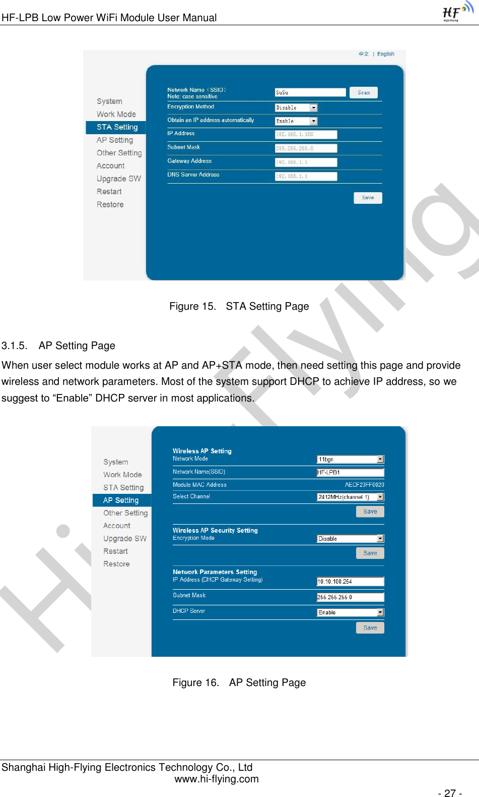
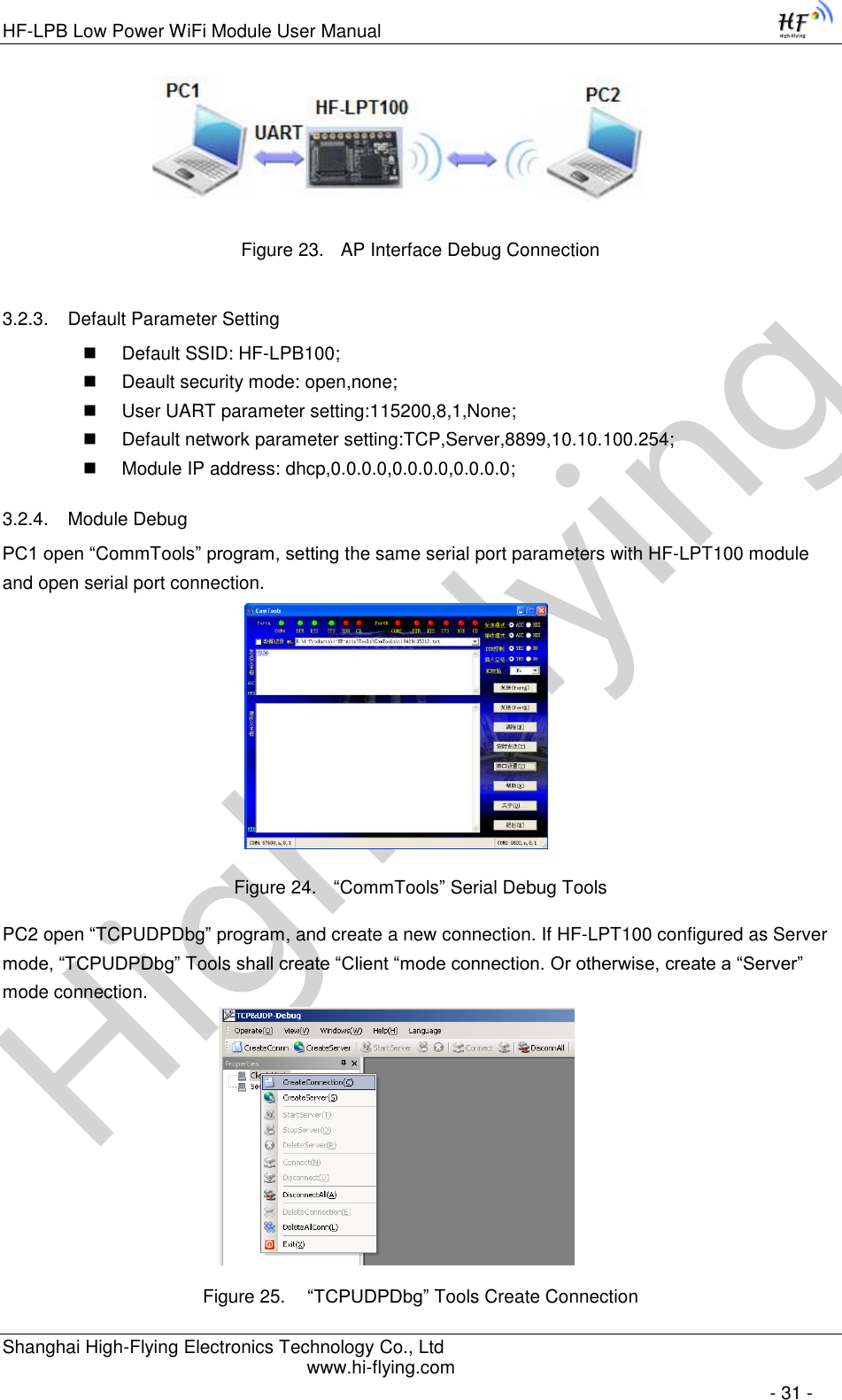
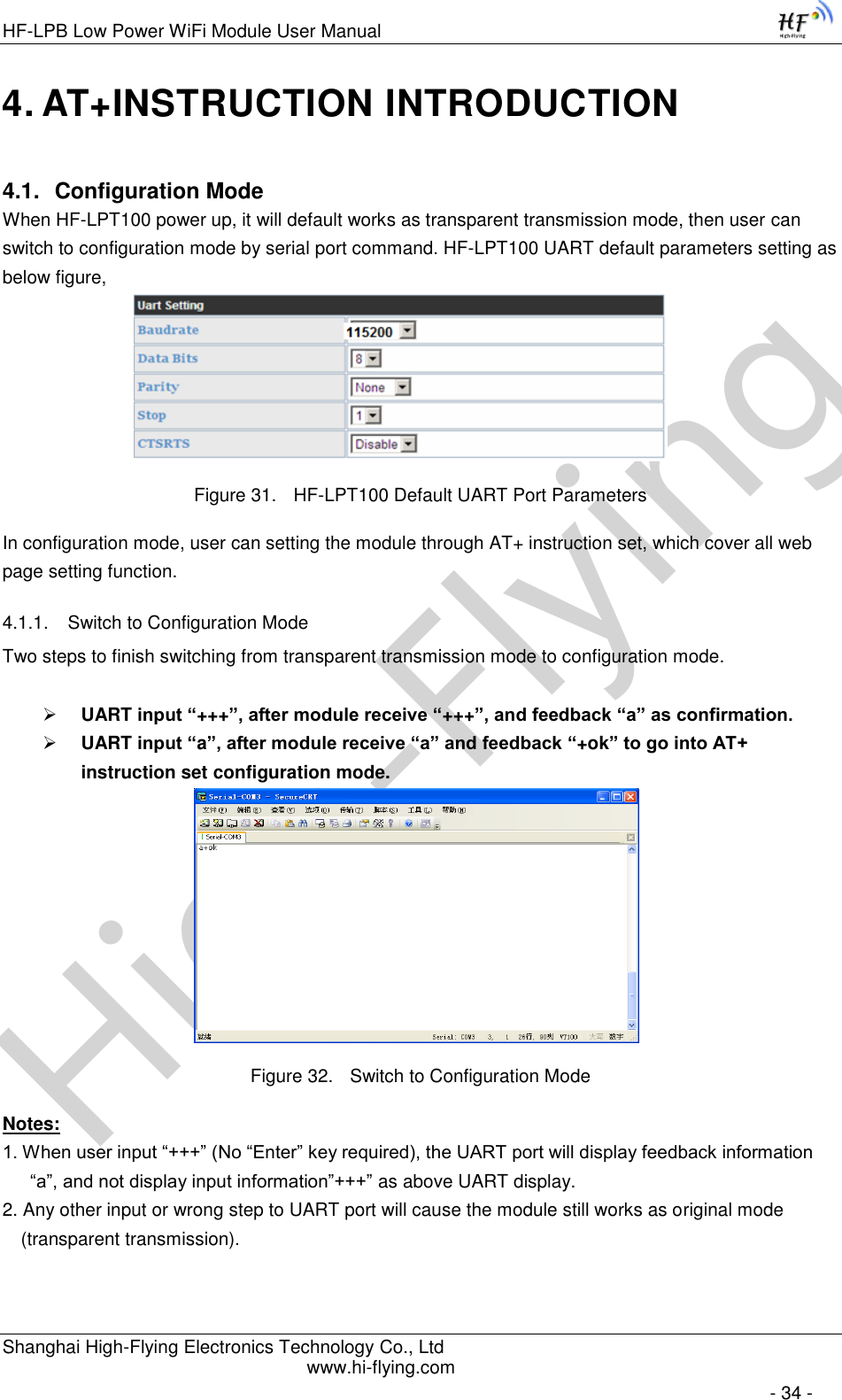
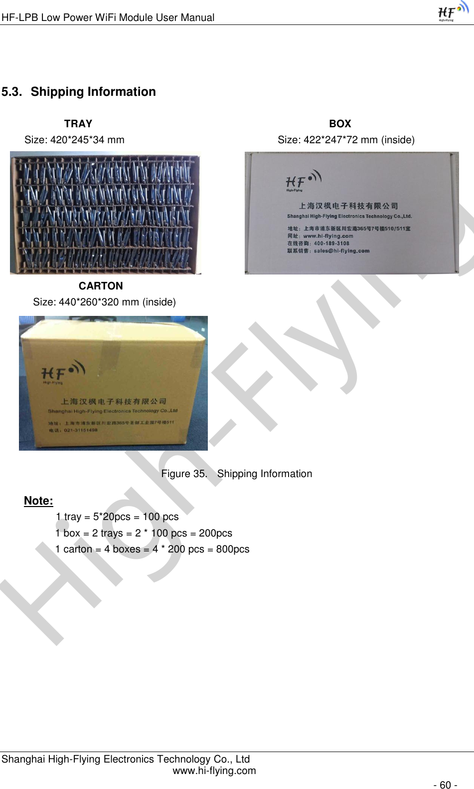
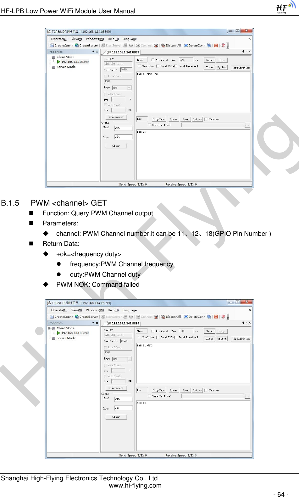
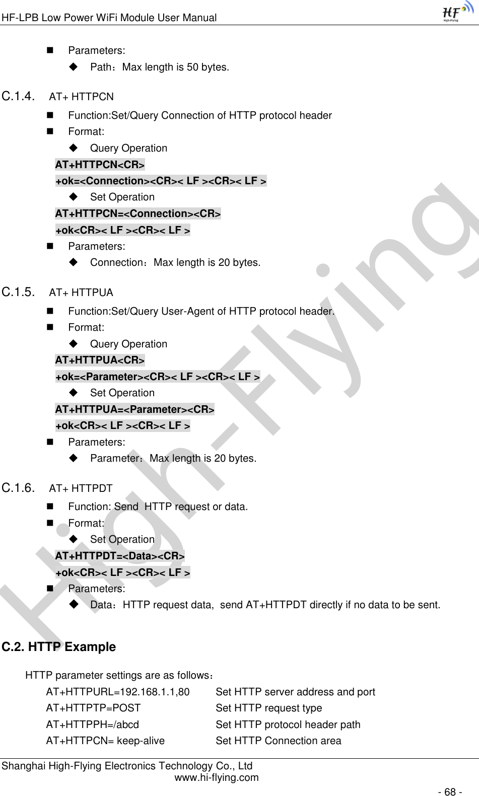
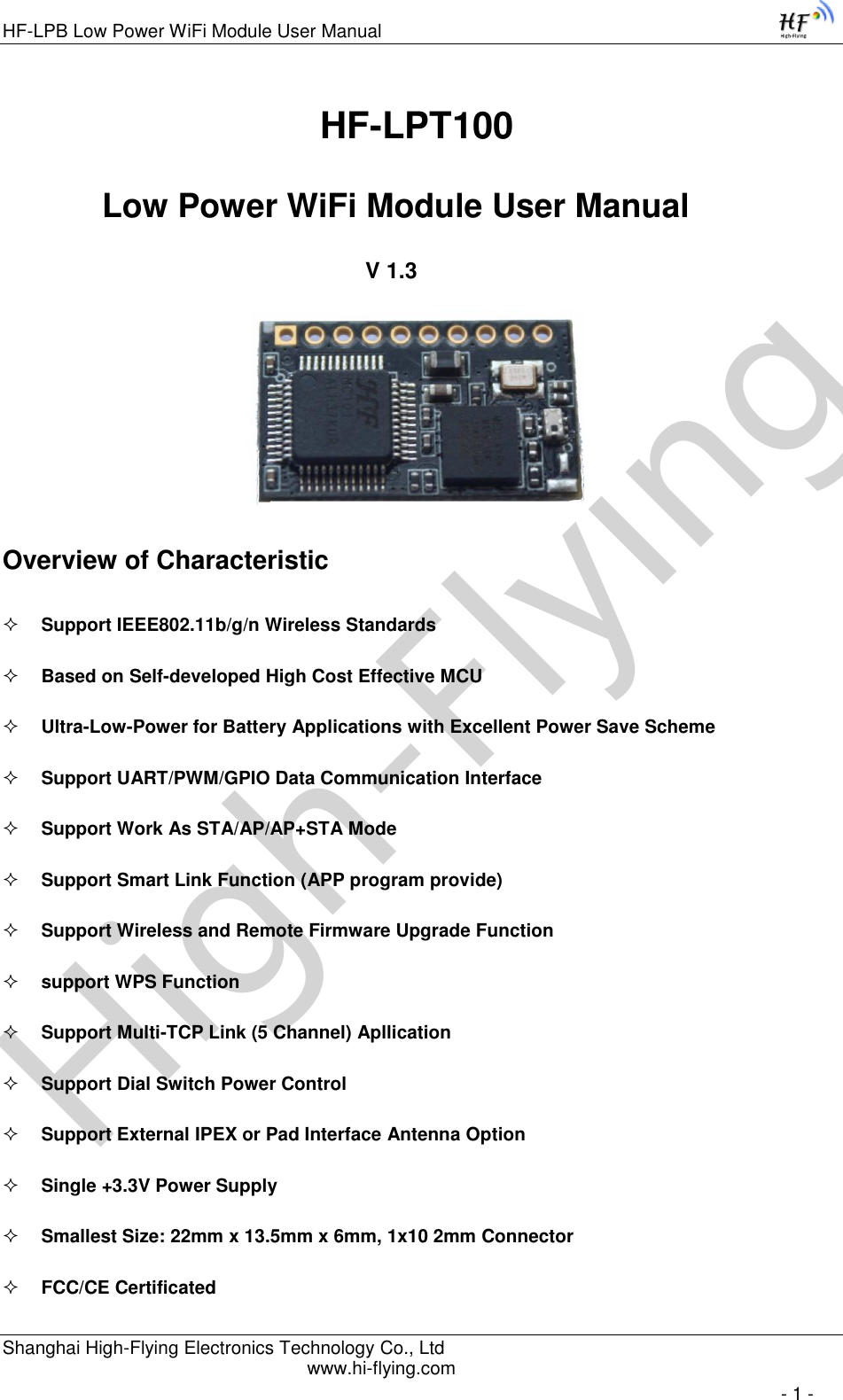
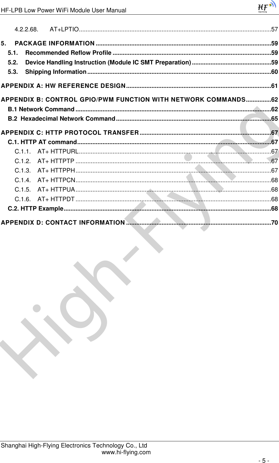
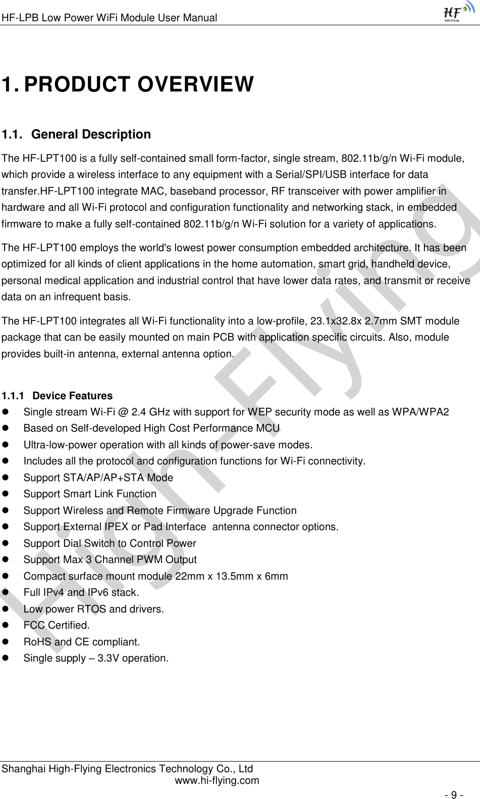
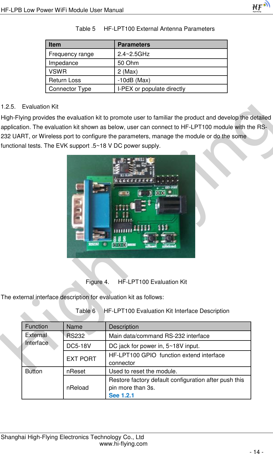
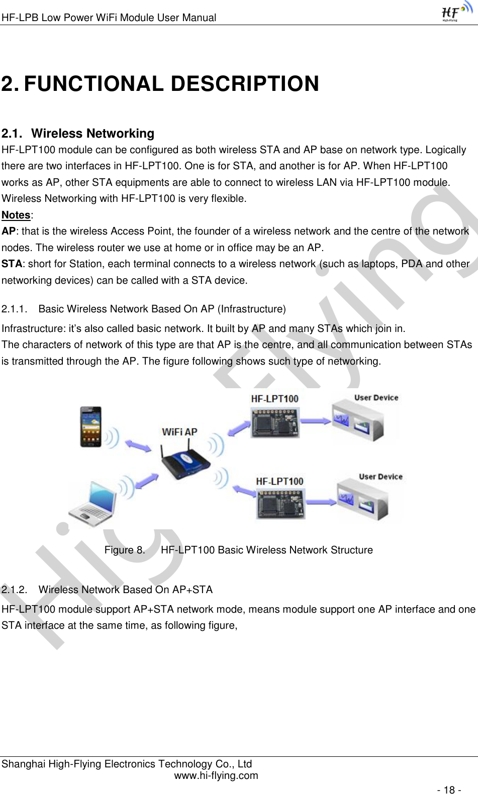
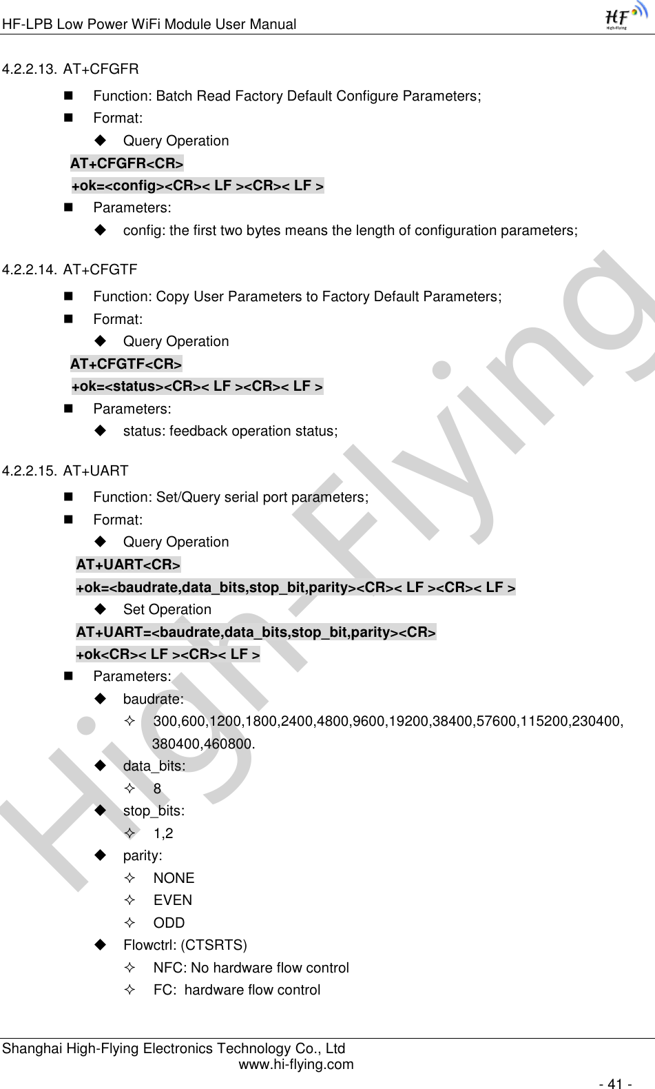
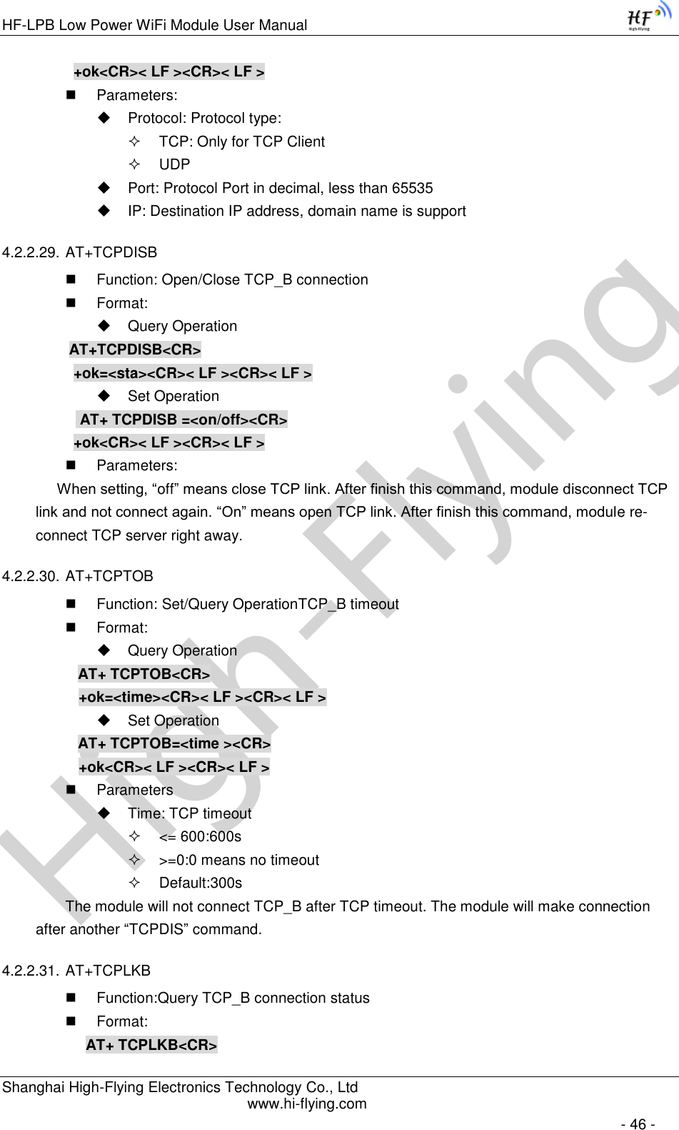
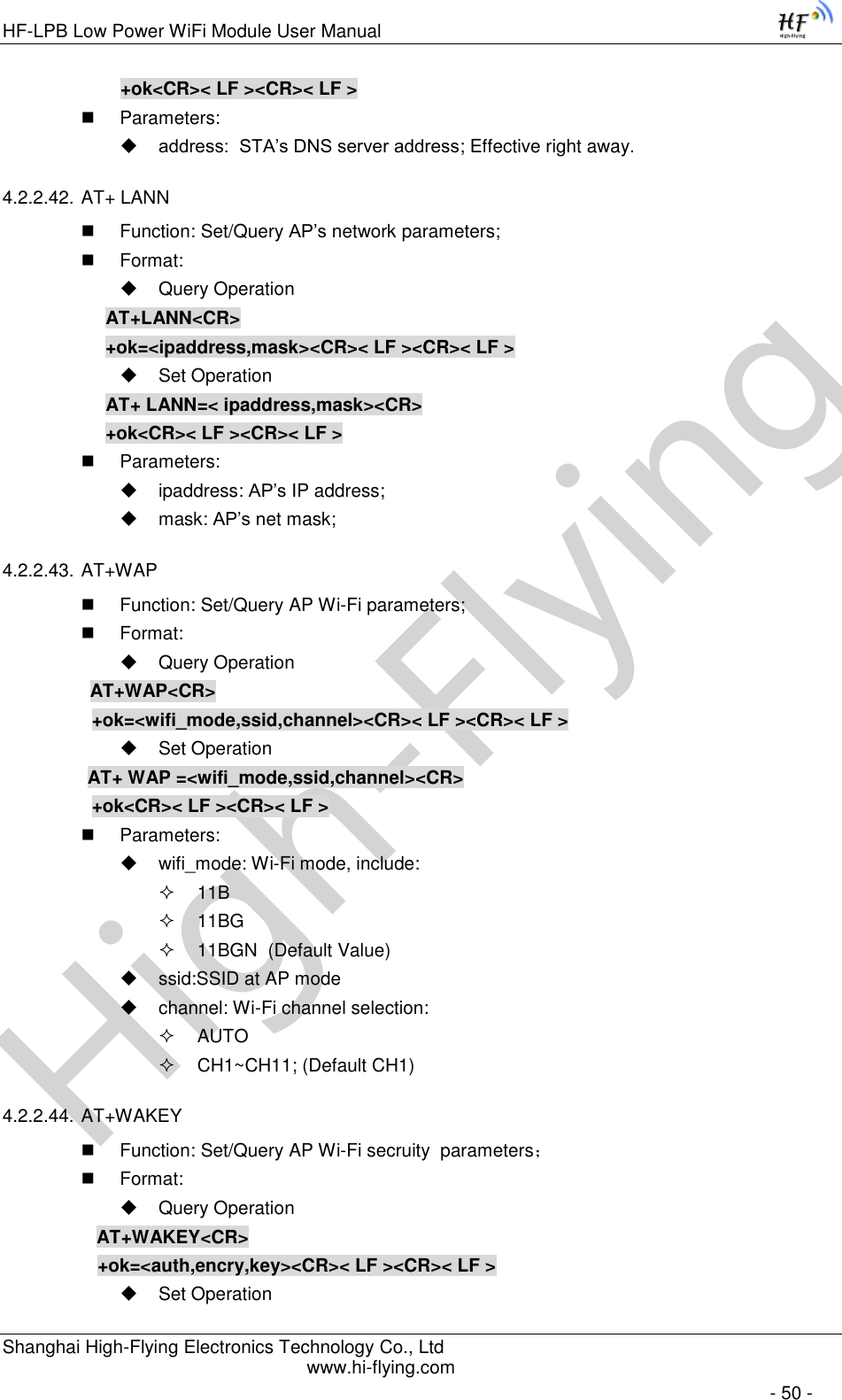
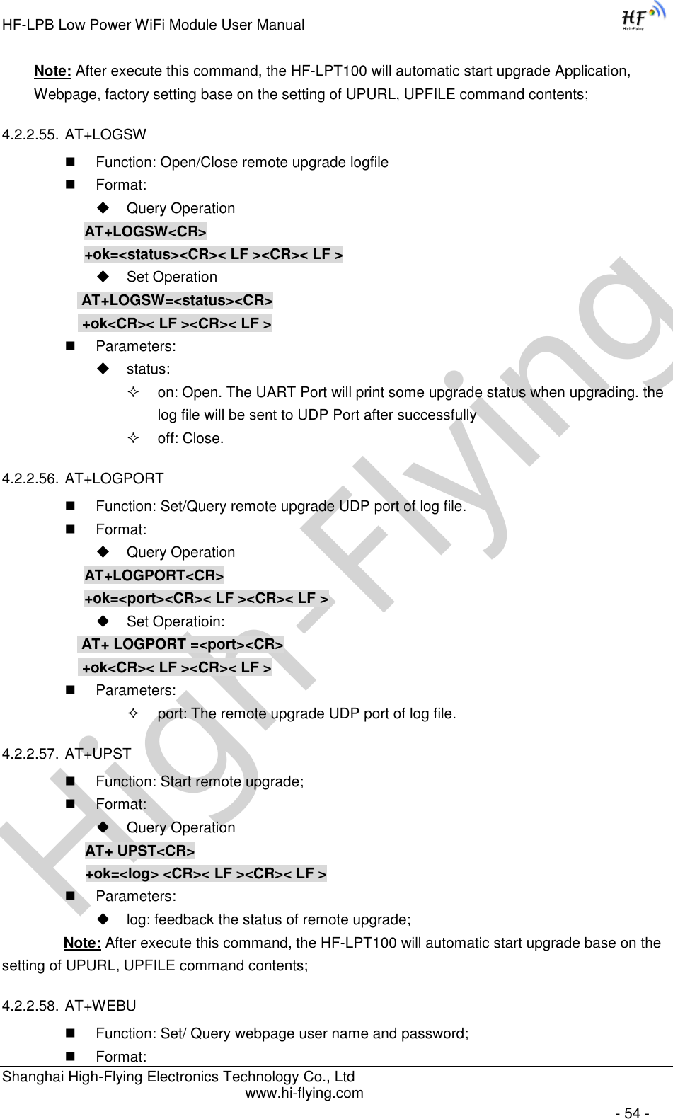
![High-FlyingHF-LPB Low Power WiFi Module User Manual Shanghai High-Flying Electronics Technology Co., Ltd www.hi-flying.com - 35 - 4.2. AT+ Instruction Set Overview User can input AT+ Instruction through hyper terminal or other serial debug terminal, also can program the AT+ Instruction to script. User can also input “AT+H” to list all AT+ Instruction and description to start. Figure 33. ”AT+H” Instruction for Help 4.2.1. Instruction Syntax Format AT+Instruction protocol is based on the instruction of ASCII command style, the description of syntax format as follow. Format Description < >: Means the parts must be included [ ]: Means the optional part Command Message AT+<CMD>[op][para-1,para-2,para-3,para-4…]<CR> AT+: Prefix of command message; CMD: Command string; [op]: Symbol of command operator, “=” : The command requires parameters input; “NULL”: Query the current command parameters setting; [para-n]: Parameters input for setting if required; <CR>:”Enter” Key, it’s 0x0a or 0x0d in ASCII;](https://usermanual.wiki/High-Flying-Electronics-Technology/HF-LPT100/User-Guide-2151877-Page-35.png)
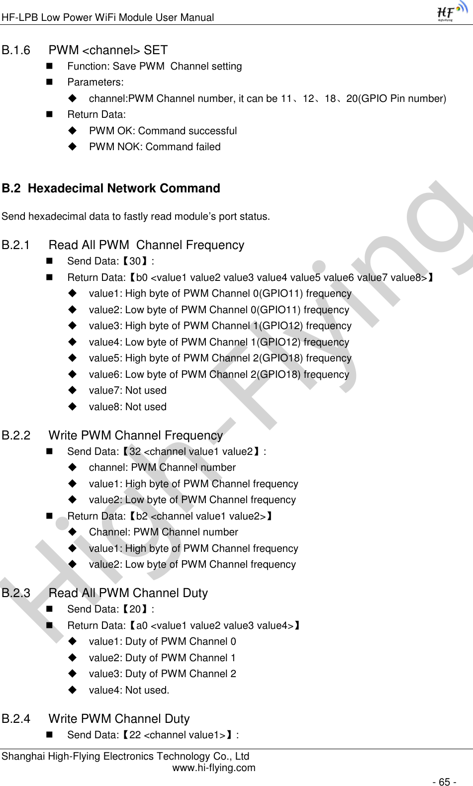
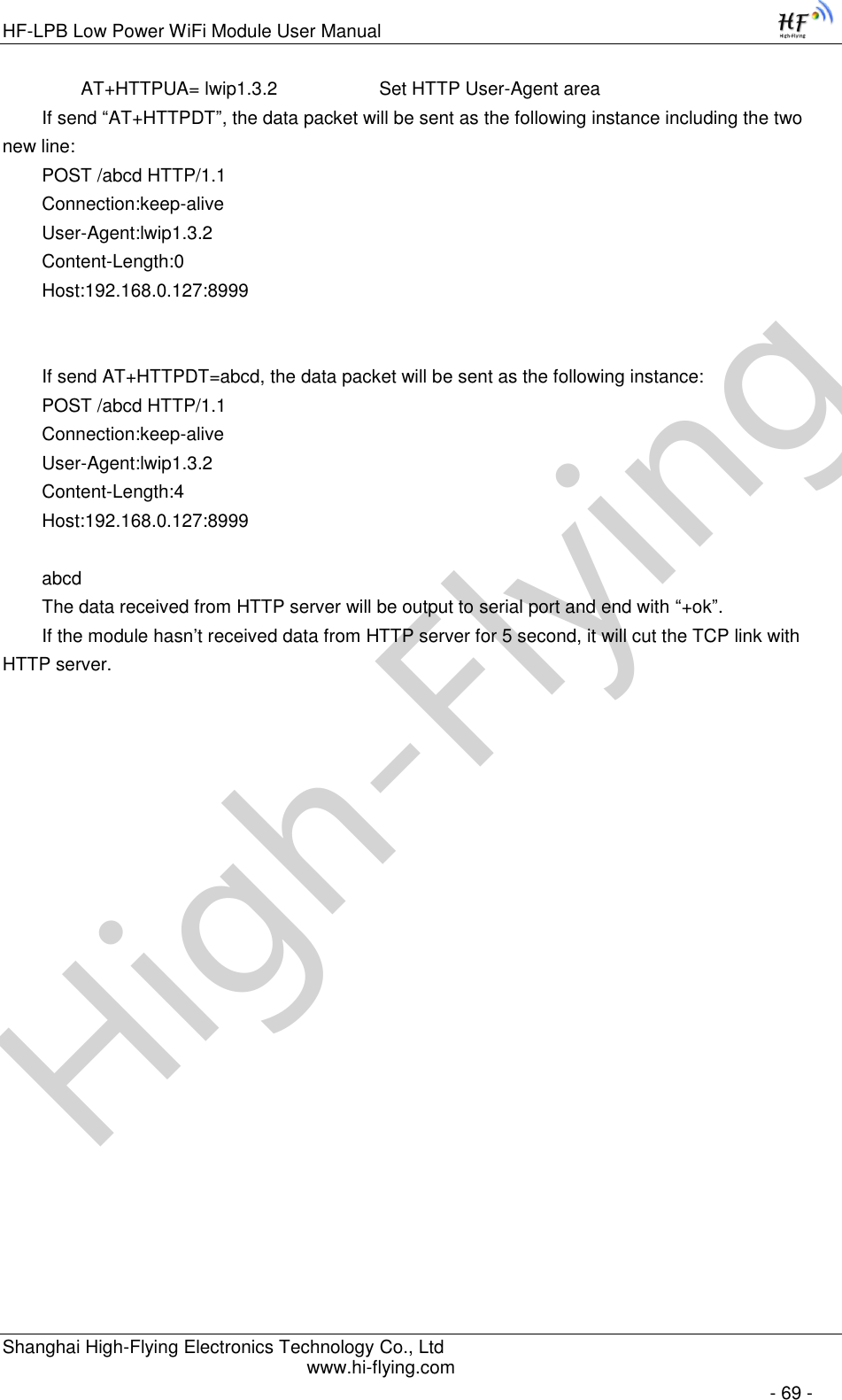
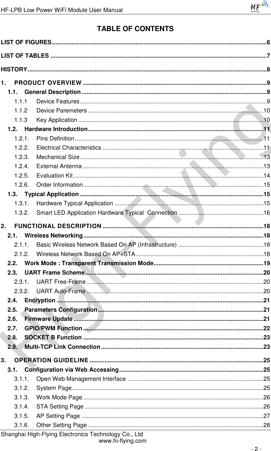
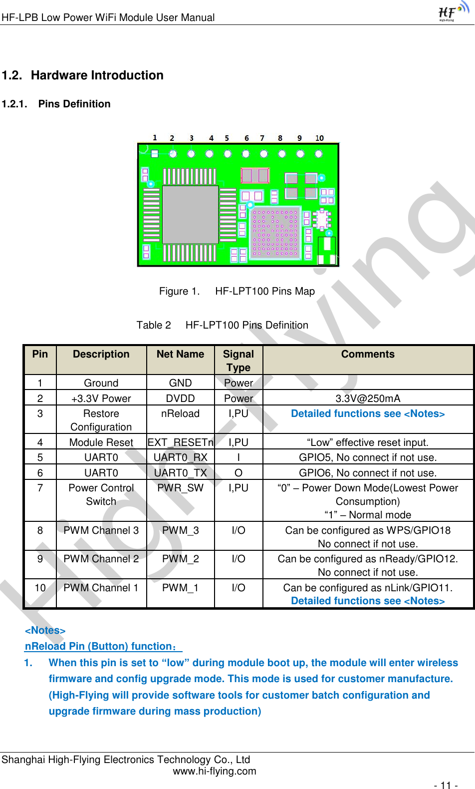
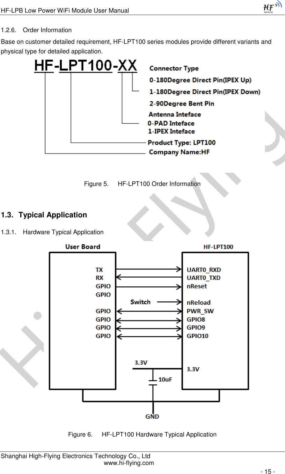
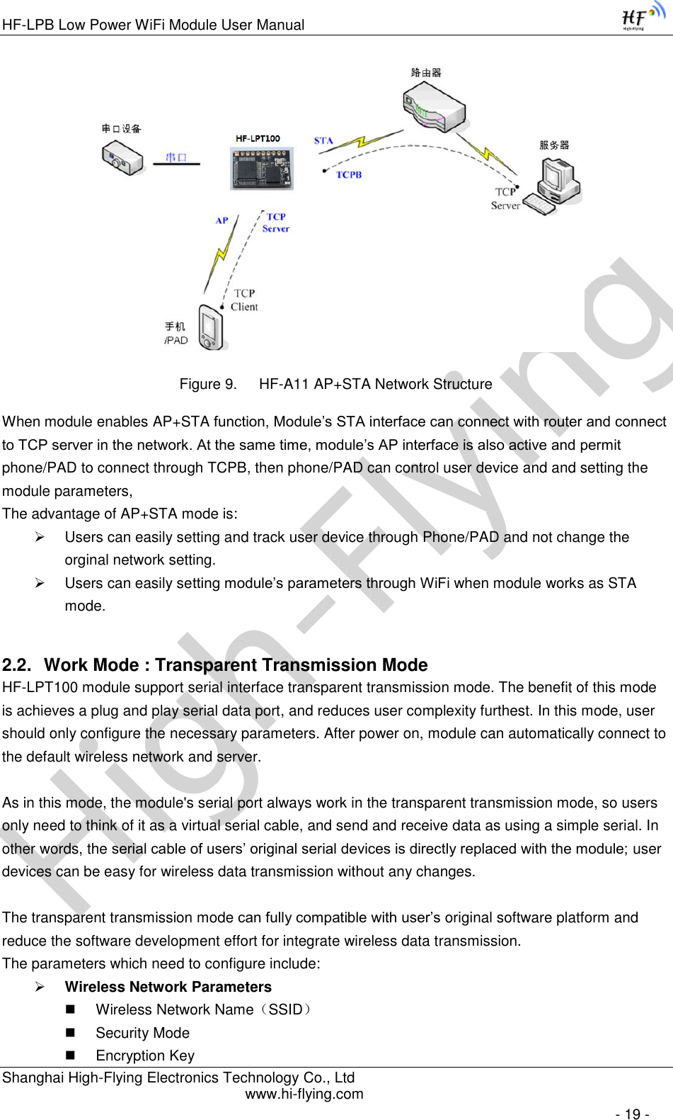
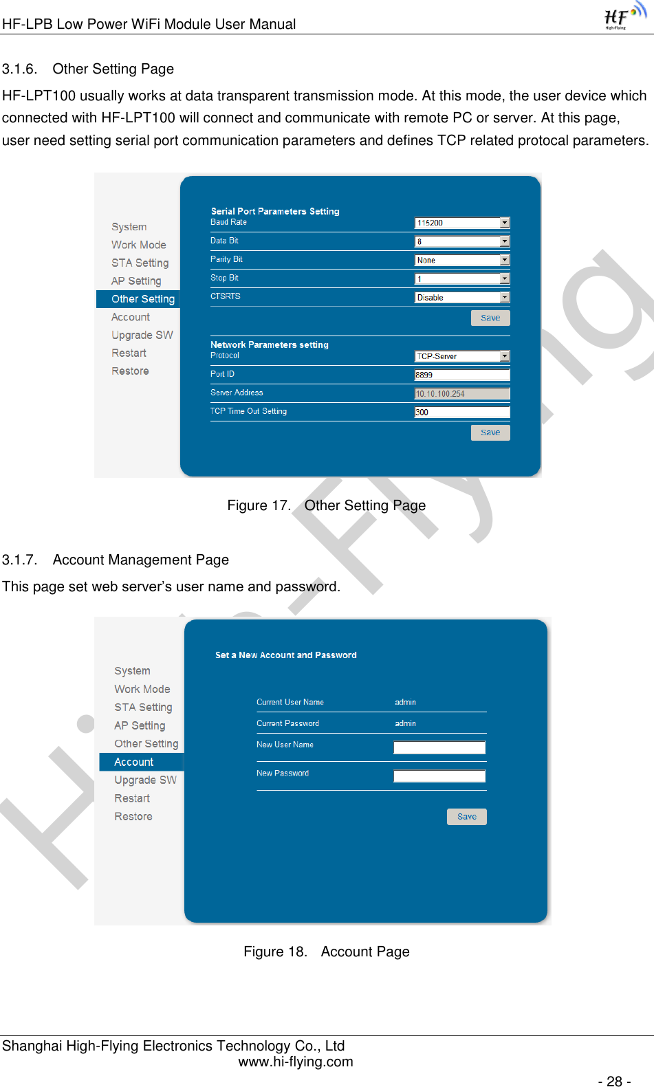
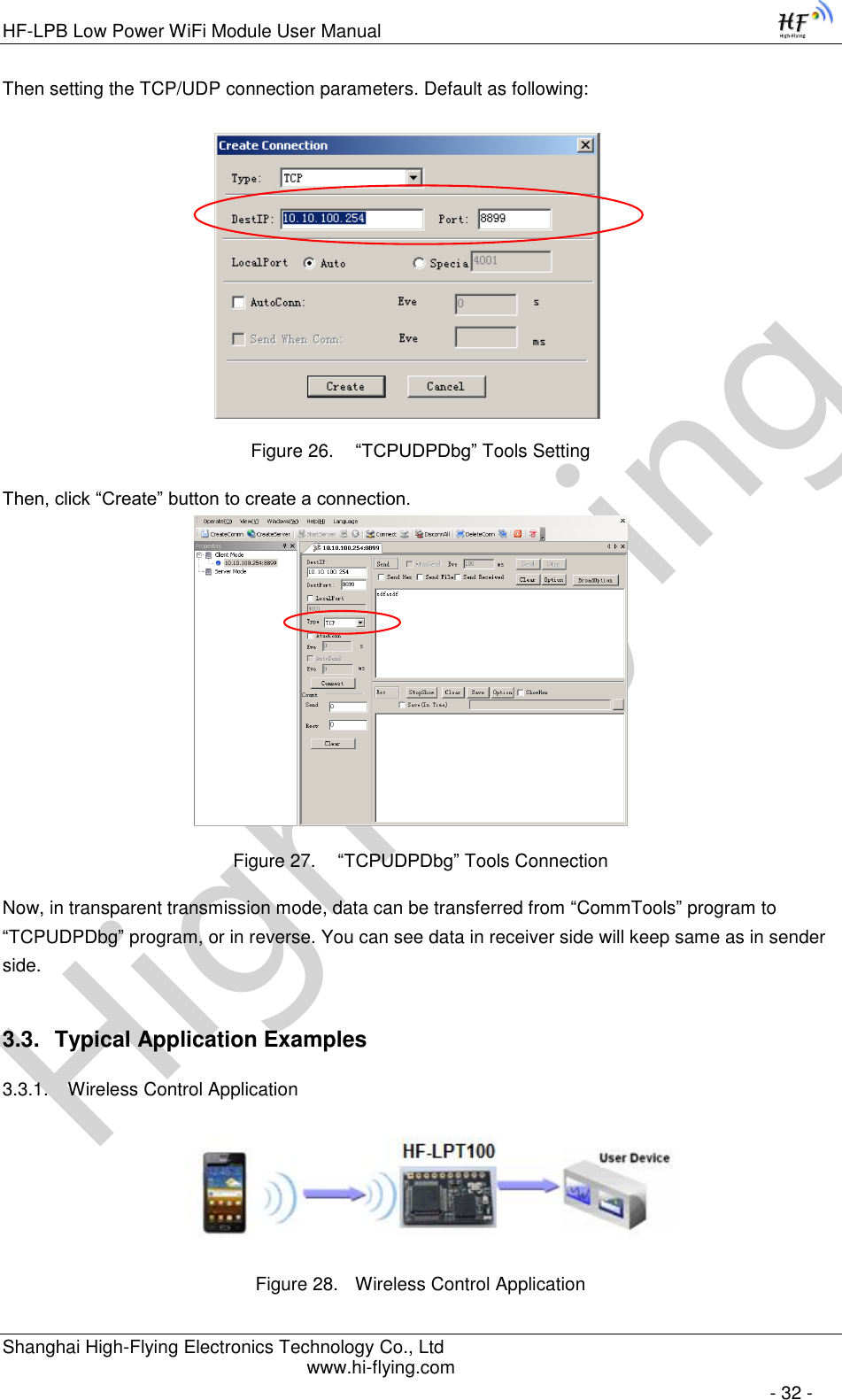
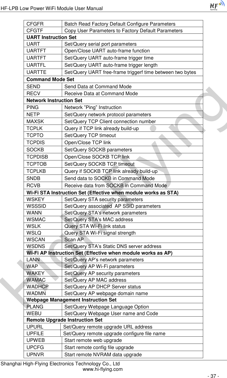
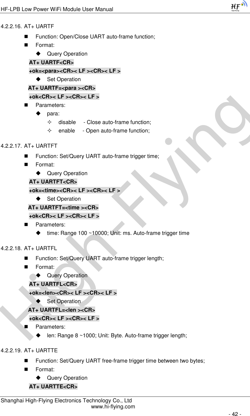
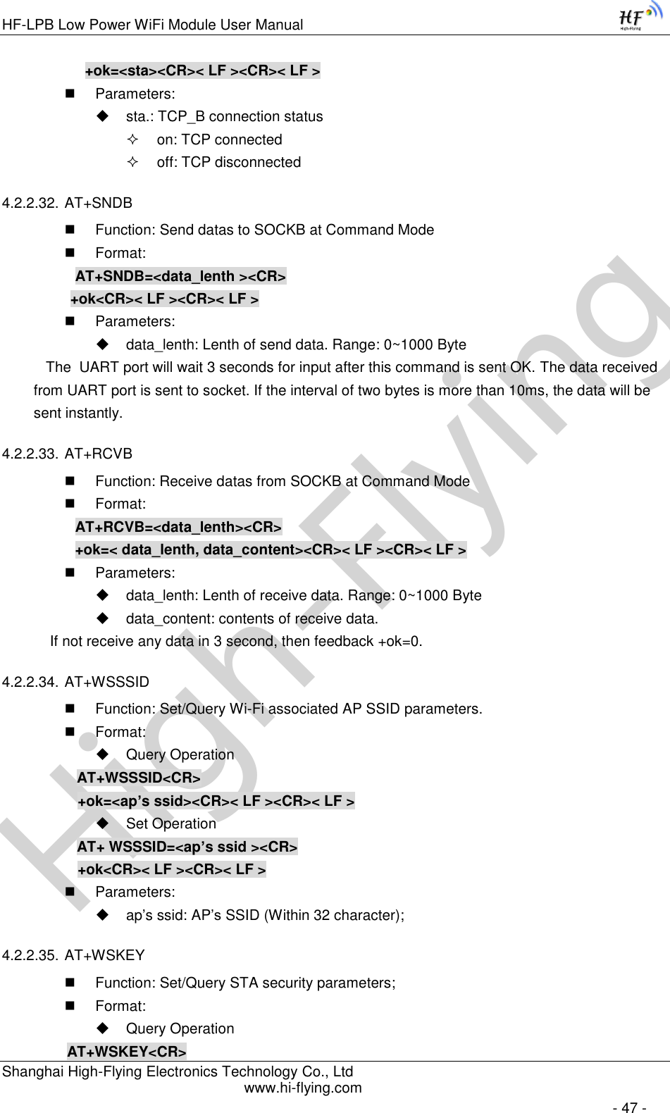
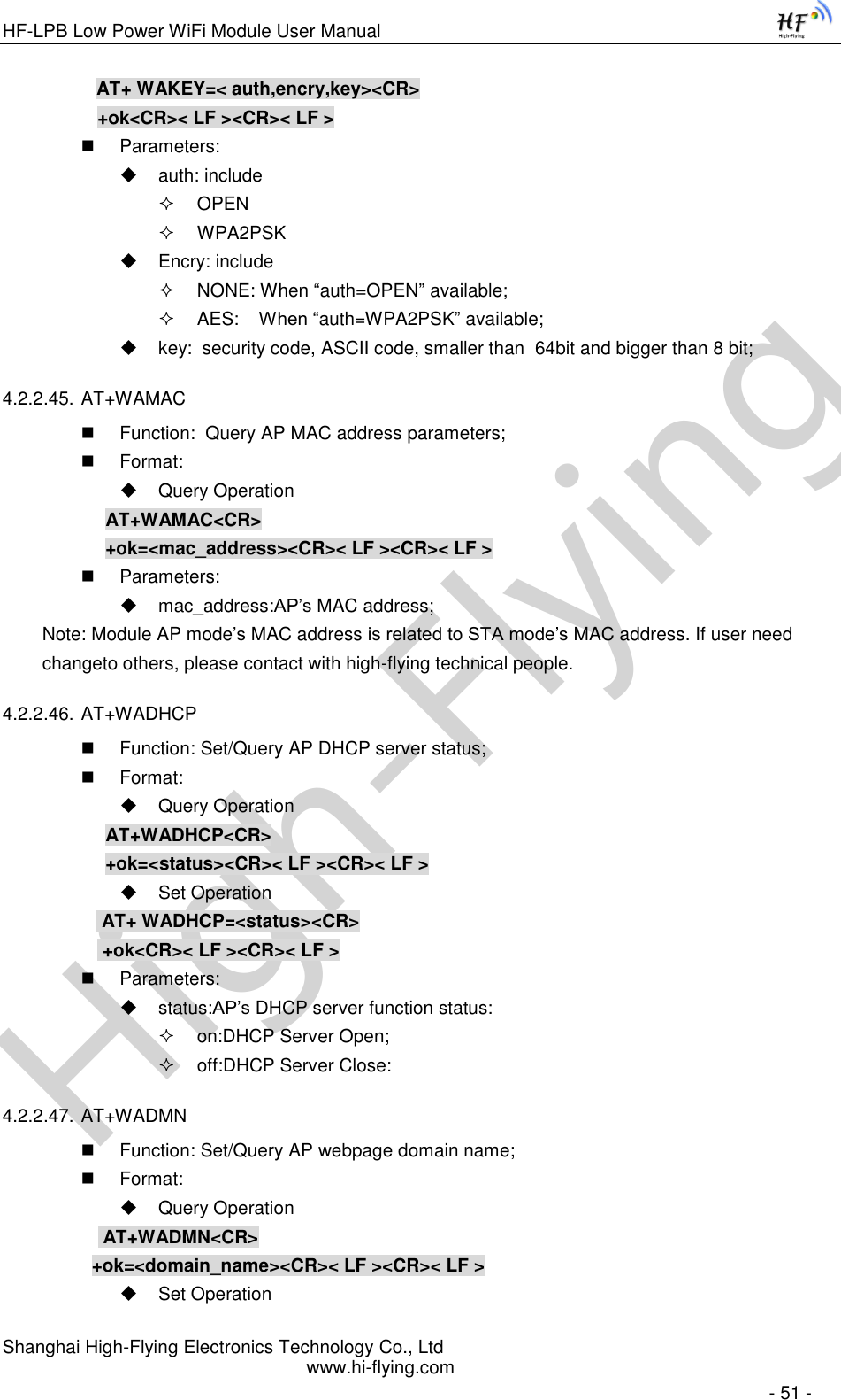
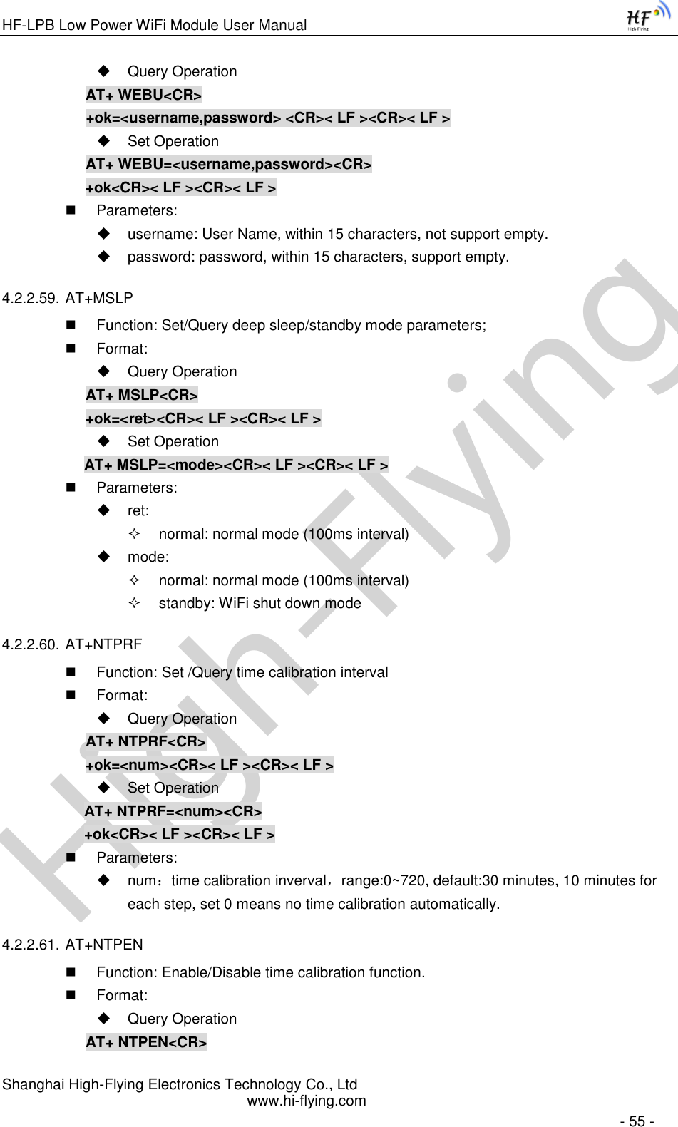
![High-FlyingHF-LPB Low Power WiFi Module User Manual Shanghai High-Flying Electronics Technology Co., Ltd www.hi-flying.com - 36 - Notes: When input AT+Instruction, “AT+<CMD>” character will display capital letter automatic and other parts will not change as you input. Response Message +<RSP>[op] [para-1,para-2,para-3,para-4…]<CR><LF><CR><LF> +: Prefix of response message; RSP: Response string; “ok” : Success “ERR”: Failure [op] : = [para-n]: Parameters if query command or Error code when error happened; <CR>: ASCII 0x0d; <LF>: ASCIII 0x0a; Error Code Table 9 Error Code Describtion Error Code Description -1 Invalid Command Format -2 Invalid Command -3 Invalid Operation Symbol -4 Invalid Parameter -5 Operation Not Permitted 4.2.2. AT+ Instruction Set Table 10 AT+ Instruction Set List Instruction Description <null> NULL Managment Instruction Set E Open/Close show back function WMODE Set/Query Wi-Fi work mode (AP/STA/APSTA) ENTM Set module into transparent transition mode TMODE Set/Query module data transfer mode MID Query module ID information VER Query module software version information RELD Restore to factory default setting FCLR Erase factory setting Z Re-start module H Help Configure Parameters Instruction Set CFGRD Batch Read User Configure Parameters CFGWR Batch Write Configure Parameters](https://usermanual.wiki/High-Flying-Electronics-Technology/HF-LPT100/User-Guide-2151877-Page-36.png)

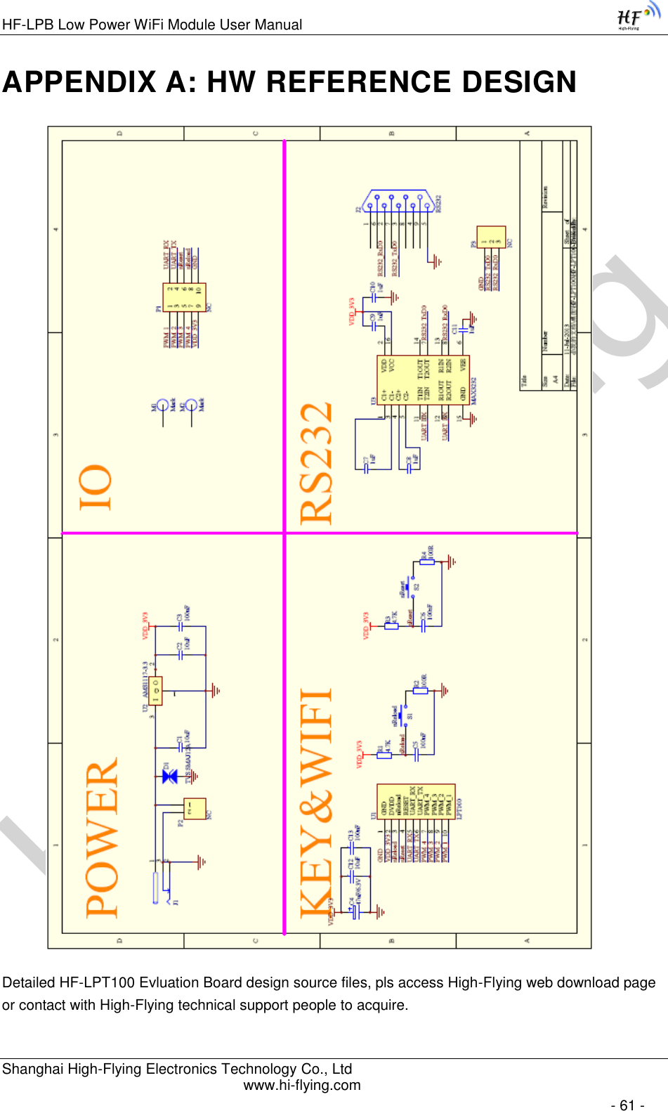
![High-FlyingHF-LPB Low Power WiFi Module User Manual Shanghai High-Flying Electronics Technology Co., Ltd www.hi-flying.com - 57 - Format: Query Operation AT+ ASWD<CR> +ok=<aswd> <CR>< LF ><CR>< LF > Set Operation AT+ ASWD=<aswd> <CR>< LF ><CR>< LF > Parameters: aswd: WiFi Configuration Password (within 20 characters). 4.2.2.66. AT+MDCH Function: Set Wi-Fi Auto Switch Function Format: Query Operation AT+ MDCH<CR> +ok=<mode> <CR>< LF ><CR>< LF > Set Operation AT+ MDCH=<mode> <CR>< LF ><CR>< LF > Parameters: mode: Wi-Fi Auto Switch Mode off: Disable Wi-Fi auto switch. on: Enable Wi-Fi auto switch. When the module(STA mode) fail to connect to router, it will switch to AP mode itself in one minute. auto: Enable Wi-Fi auto detect function. The module will reset itself when encounter any abnormal. The default time interval is 10 minutes. 3-120: unit: minute. Set the time interval to reset itself when abnormal. 4.2.2.67. AT+TXPWR Function: Set/Query Wi-Fi Transmit Power, Real Transmit Power=Default Transmit Power(16dBm) – [Setting Value] * 0.5dBm Format: Query Operation AT+TXPWR <CR> +ok=<num><CR>< LF><CR>< LF> Set Operation AT+TXPWR=<num><CR> +ok<CR>< LF><CR>< LF> Parameters: num: [Setting Value]. The default is 0, it can be sent from 0 ~ 24. If set to 24, the moudule transmit power will be at a minium of 4dBm. Reboot to make this setting change valid. It will not restore to default if reload the module. 4.2.2.68. AT+LPTIO Function: Enable/Disable module’s nReady、nLink function](https://usermanual.wiki/High-Flying-Electronics-Technology/HF-LPT100/User-Guide-2151877-Page-57.png)