High Flying Electronics Technology HF-LPT120A HF-LPT120A User Manual
High-Flying Electronics Technology Co., Ltd. HF-LPT120A Users Manual
UserManual.wiki
>
High Flying Electronics Technology
>
HF LPT120A User Manual
User manual
Navigation menu
Upload a User Manual
Namespaces
Wiki Guide
HTML
PDF
Info
Views
User Manual
Discussion / Help
Navigation
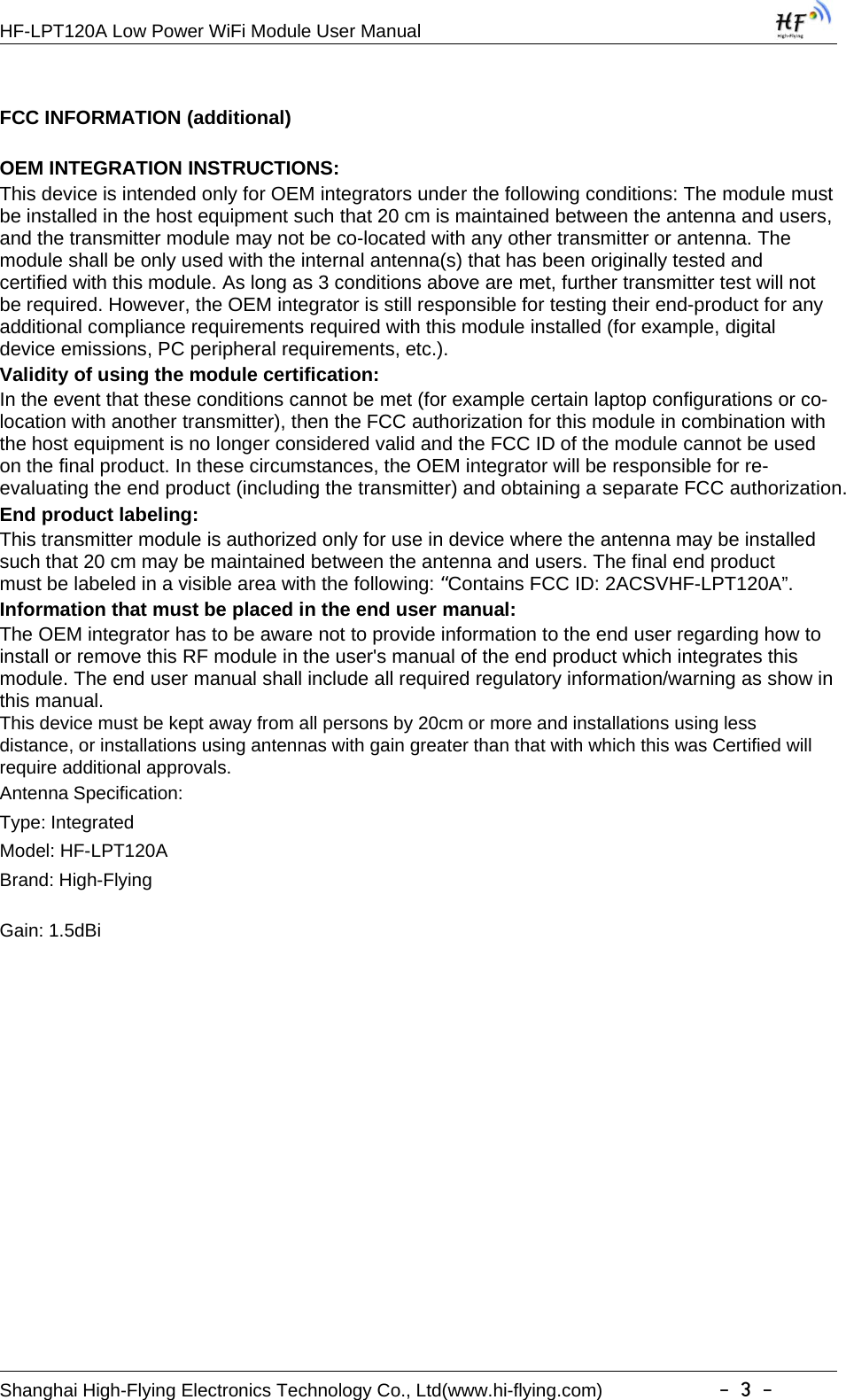
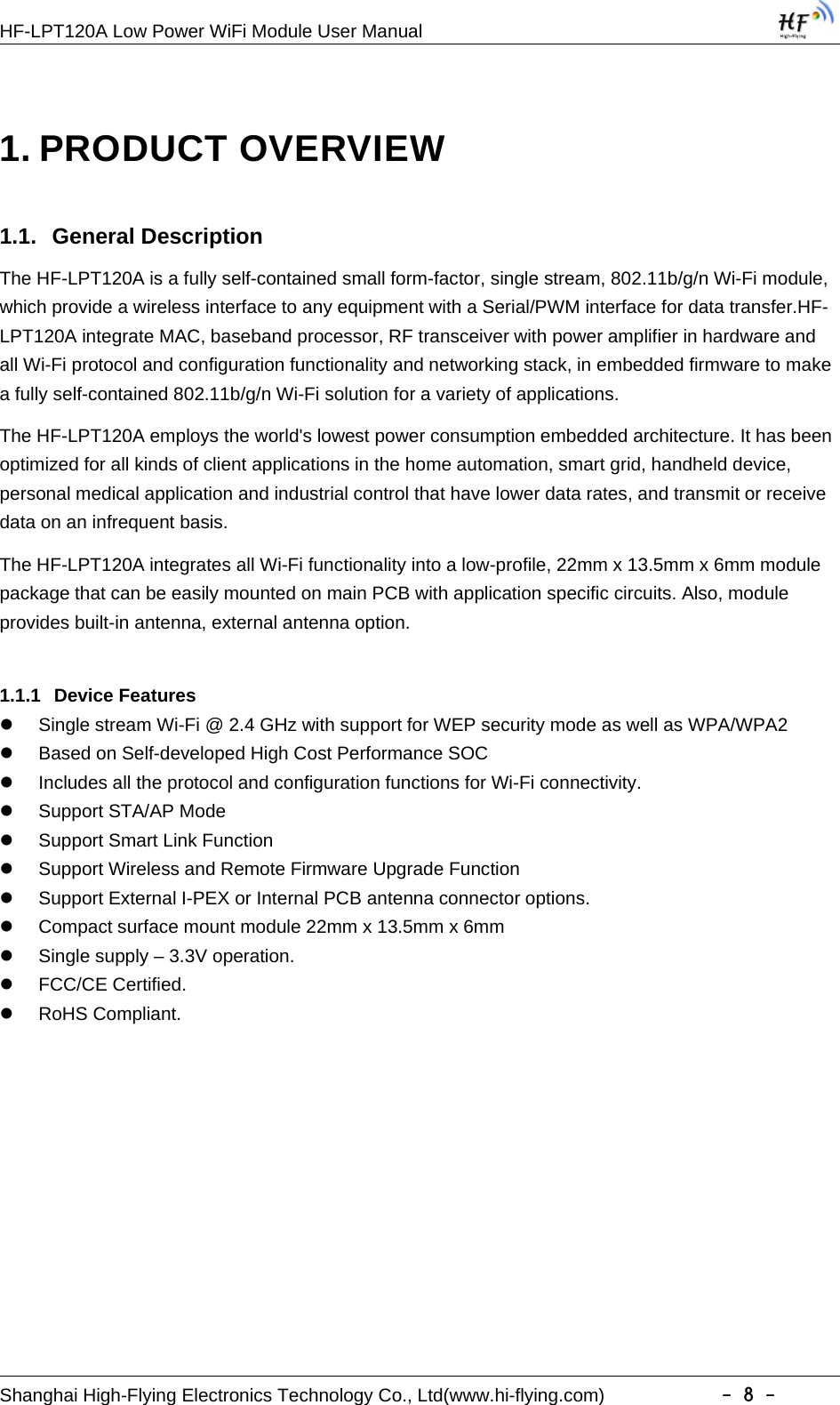
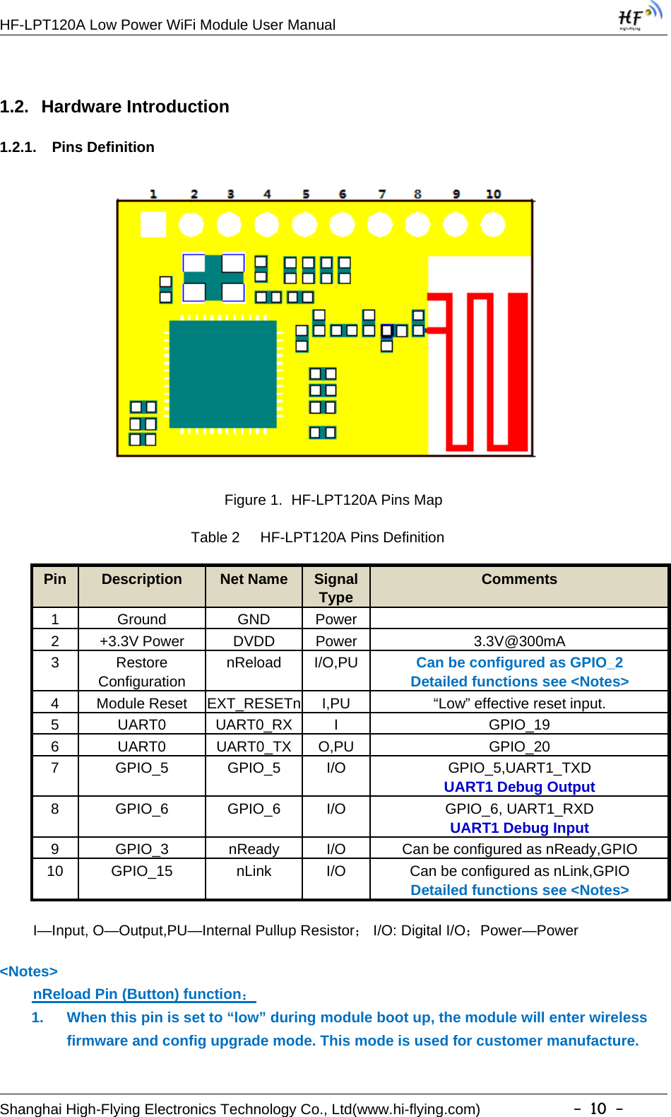
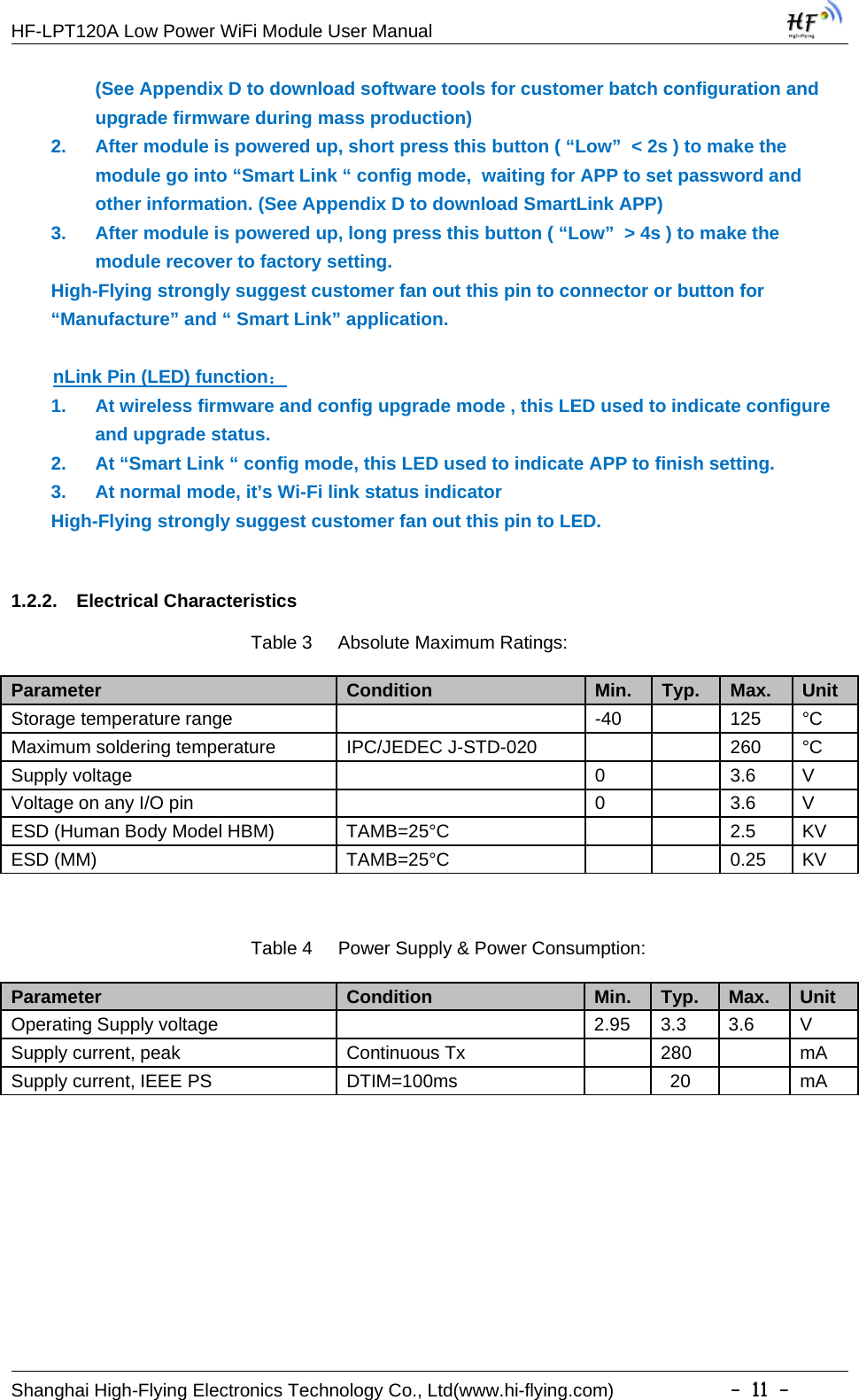
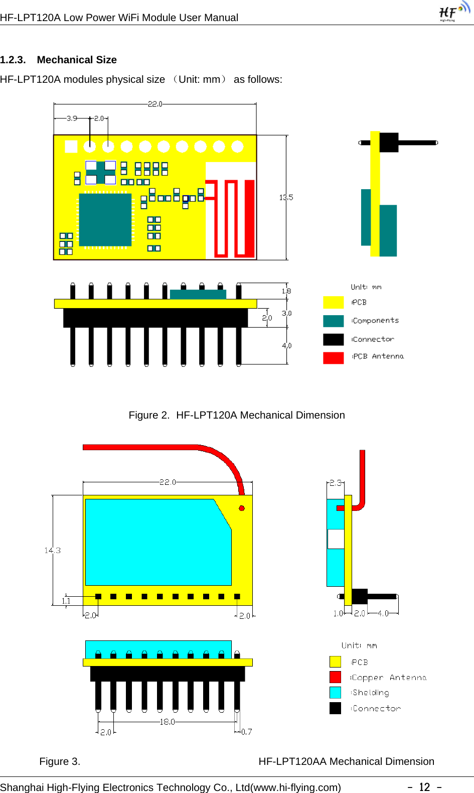
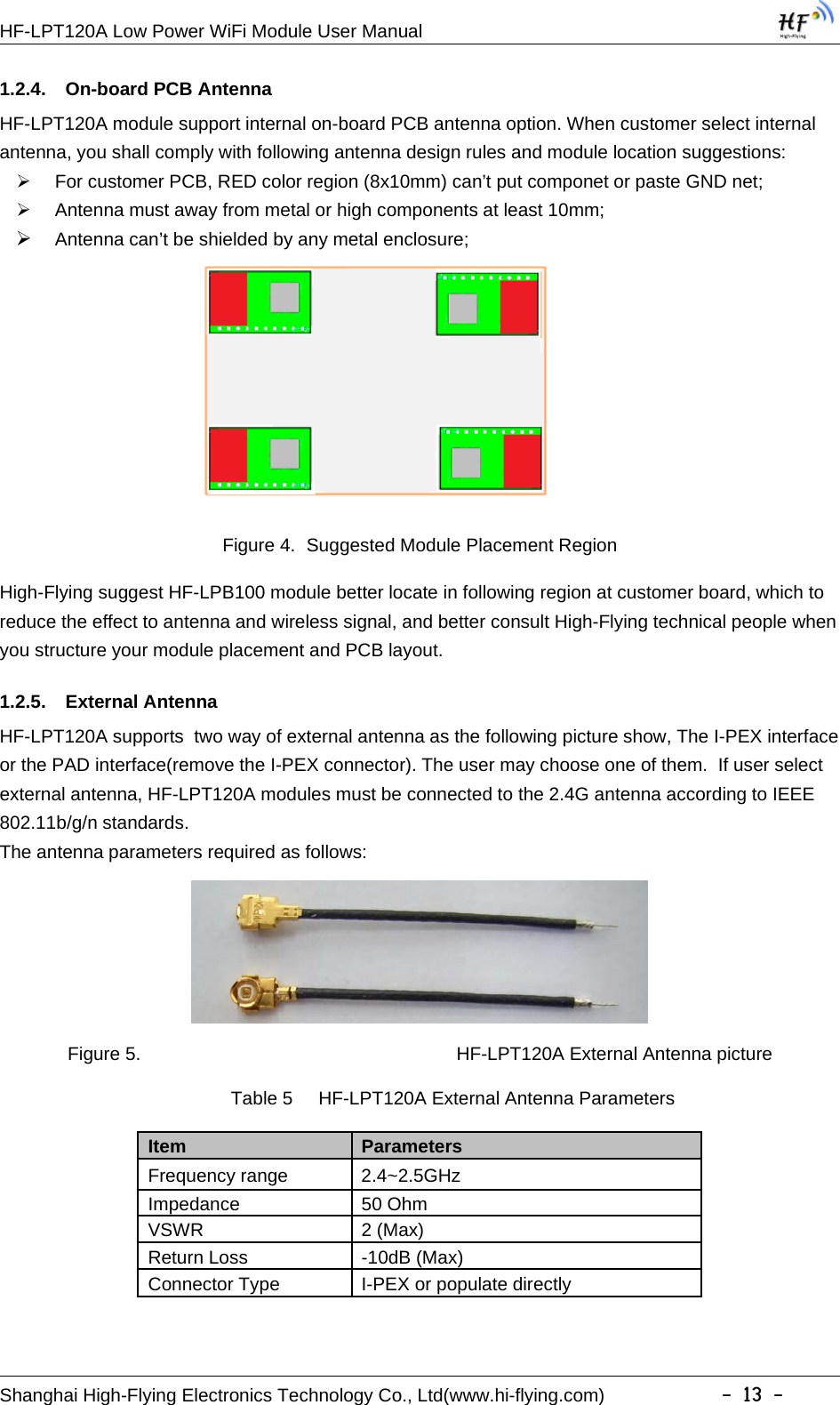
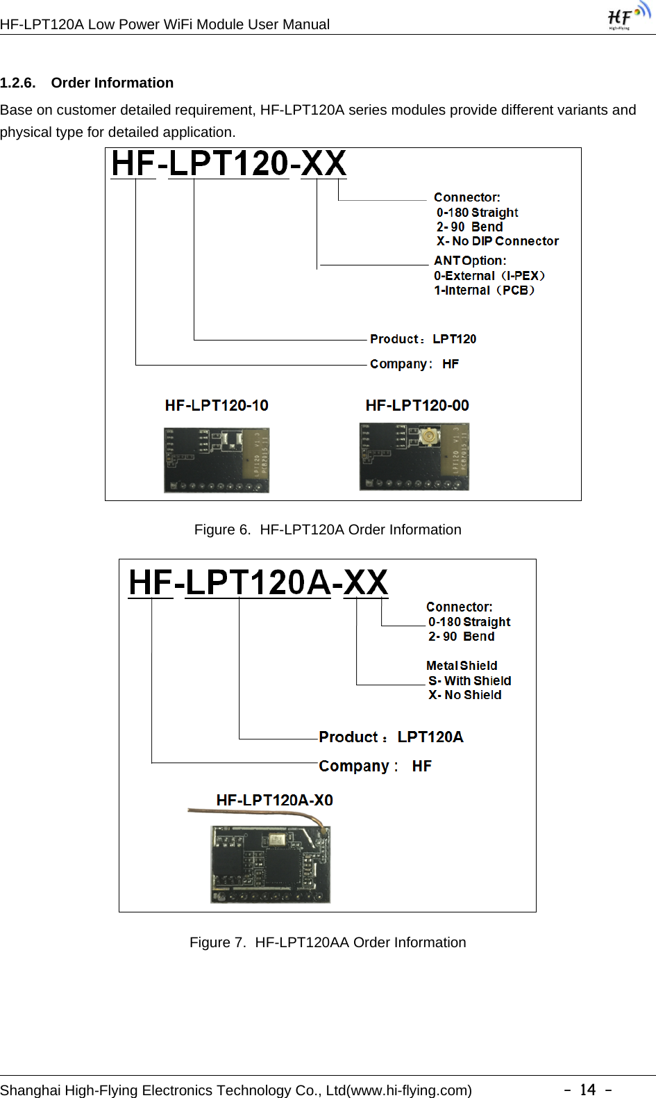
![HF-LPT120A Low Power WiFi Module User ManualShanghai High-Flying Electronics Technology Co., Ltd(www.hi-flying.com) -9-1.1.2 Device ParemetersTable 1 HF-LPT120A Module Technical SpecificationsClass Item ParametersWirelessParametersCertification FCC/CEWireless standard 802.11 b/g/nFrequency range 2.412GHz-2.462GHzTransmit Power802.11b: +16 +/-2dBm (@11Mbps)802.11g: +14 +/-2dBm (@54Mbps)802.11n: +13 +/-2dBm (@HT20, MCS7)Receiver Sensitivity802.11b: -93 dBm (@11Mbps ,CCK)802.11g: -85 dBm (@54Mbps, OFDM)802.11n: -82 dBm (@HT20, MCS7)Antenna Option External:I-PEX ConnectorInternal:PCB PrintedAntennaHardwareParametersData Interface UARTGPIOOperating Voltage 2.95~3.6VOperating Current Peak [Continuous TX]: ~280mAAverage. ~20mAOperating Temp. -20℃-85℃Storage Temp. -40℃-125℃Dimensions and Size 22mm x 13.5mm x 6mmExternal Interface 1x10, 2mm DIPSoftwareParametersNetwork Type STA /APSecurity Mechanisms WEP/WPA-PSK/WPA2-PSKEncryption WEP64/WEP128/TKIP/AESUpdate Firmware Local Wireless, RemoteCustomization Support customizationNetwork Protocol IPv4, TCP/UDP/HTTPUser Configuration AT+instruction set. Android/ iOSSmart Link APP tools1.1.3 Key ApplicationRemote equipment monitoringAsset tracking and telemetrySecurityIndustrial sensors and controlsHome automationMedical devices](https://usermanual.wiki/High-Flying-Electronics-Technology/HF-LPT120A/User-Guide-3026350-Page-9.png)