High Flying Electronics Technology HF-LPT120A HF-LPT120A User Manual
High-Flying Electronics Technology Co., Ltd. HF-LPT120A Users Manual
User manual
HF-LPT120A Low Power WiFi Module User Manual
Shanghai High-Flying Electronics Technology Co., Ltd(www.hi-flying.com) -1-
HF-LPT120A
Low Power WiFi Module User Manual
V1.3
Overview of Characteristic
Support IEEE802.11b/g/n Wireless Standards
Based on Self-developed High Cost Effective SOC
Support UART/GPIO Data Communication Interface
Support Work As STA/AP Mode
Support Smart Link Function (APP program provide)
Support Wireless and Remote Firmware Upgrade Function
support WPS Function
Support External I-PEX or Internal PCB Antenna Option
Single +3.3V Power Supply
Smallest Size: 22mm x 13.5mm x 6mm, 1x10 2mm Connector
FCC/CE Certificated

HF-LPT120A Low Power WiFi Module User Manual
Shanghai High-Flying Electronics Technology Co., Ltd(www.hi-flying.com) -2-
FCC STATEMENT :
This device complies with Part 15 of the FCC Rules. Operation is subject to the following two
conditions:
(1) This device may not cause harmful interference, and
(2) This device must accept any interference received, including interference that may cause
undesired operation.
Warning: Changes or modifications not expressly approved by the party responsible for
compliance could void the user's authority to operate the equipment.
NOTE: This equipment has been tested and found to comply with the limits for a Class B digital
device, pursuant to Part 15 of the FCC Rules. These limits are designed to provide reasonable
protection against harmful interference in a residential installation. This equipment generates
uses and can radiate radio frequency energy and, if not installed and used in accordance with the
instructions, may cause harmful interference to radio communications. However, there is no
guarantee that interference will not occur in a particular installation. If this equipment does cause
harmful interference to radio or television reception, which can be determined by turning the
equipment off and on, the user is encouraged to try to correct the interference by one or more of
the following measures:
Reorient or relocate the receiving antenna.
Increase the separation between the equipment and receiver.
Connect the equipment into an outlet on a circuit different from that to which the receiver is
connected.
Consult the dealer or an experienced radio/TV technician for help.
FCC Radiation Exposure Statement:
This equipment complies with FCC radiation exposure limits set forth for an uncontrolled
environment. This equipment should be installed and operated with minimum distance 20cm
between the radiator & your body.

HF-LPT120A Low Power WiFi Module User Manual
Shanghai High-Flying Electronics Technology Co., Ltd(www.hi-flying.com) -3-
FCC INFORMATION (additional)
OEM INTEGRATION INSTRUCTIONS:
This device is intended only for OEM integrators under the following conditions: The module must
be installed in the host equipment such that 20 cm is maintained between the antenna and users,
and the transmitter module may not be co-located with any other transmitter or antenna. The
module shall be only used with the internal antenna(s) that has been originally tested and
certified with this module. As long as 3 conditions above are met, further transmitter test will not
be required. However, the OEM integrator is still responsible for testing their end-product for any
additional compliance requirements required with this module installed (for example, digital
device emissions, PC peripheral requirements, etc.).
Validity of using the module certification:
In the event that these conditions cannot be met (for example certain laptop configurations or co-
location with another transmitter), then the FCC authorization for this module in combination with
the host equipment is no longer considered valid and the FCC ID of the module cannot be used
on the final product. In these circumstances, the OEM integrator will be responsible for re-
evaluating the end product (including the transmitter) and obtaining a separate FCC authorization.
End product labeling:
This transmitter module is authorized only for use in device where the antenna may be installed
such that 20 cm may be maintained between the antenna and users. The final end product
must be labeled in a visible area with the following:
“
Contains FCC ID: 2ACSVHF-LPT120A”.
Information that must be placed in the end user manual:
The OEM integrator has to be aware not to provide information to the end user regarding how to
install or remove this RF module in the user's manual of the end product which integrates this
module. The end user manual shall include all required regulatory information/warning as show in
this manual.
This device must be kept away from all persons by 20cm or more and installations using less
distance, or installations using antennas with gain greater than that with which this was Certified will
require additional approvals.
Antenna Specification:
Type: Integrated
Model: HF-LPT120A
Brand: High-Flying
Gain: 1.5dBi

HF-LPT120A Low Power WiFi Module User Manual
Shanghai High-Flying Electronics Technology Co., Ltd(www.hi-flying.com) -4-
TABLE OF CONTENTS
LIST OF FIGURES................................................................................................................................................ 5
LIST OF TABLES.................................................................................................................................................. 6
HISTORY.................................................................................................................................................................7
1. PRODUCT OVERVIEW................................................................................................................................8
1.1. GENERAL DESCRIPTION...................................................................................................................... 8
1.1.1 DEVICE FEATURES.......................................................................................................................... 8
1.1.2 DEVICE PAREMETERS....................................................................................................................9
1.1.3 KEY APPLICATION............................................................................................................................9
1.2. HARDWARE INTRODUCTION.............................................................................................................10
1.2.1. PINS DEFINITION........................................................................................................................... 10
1.2.2. ELECTRICAL CHARACTERISTICS.............................................................................................11
1.2.3. MECHANICAL SIZE........................................................................................................................12
1.2.4. ON-BOARD PCB ANTENNA......................................................................................................... 13
1.2.5. EXTERNAL ANTENNA...................................................................................................................13
1.2.6. ORDER INFORMATION.................................................................................................................14
APPENDIX A: HW REFERENCE DESIGN...............................................................................................15
APPENDIX B: HTTP PROTOCOL TRANSFER......................................................................................16
B.1. HTTP AT COMMAND(RESERVED)................................................................................................... 16
B.1.1 AT+HTTPURL...................................................................................................................................16
B.1.2 AT+HTTPTP......................................................................................................................................16
B.1.3 AT+HTTPPH..................................................................................................................................... 16
B.1.4 AT+HTTPCN..................................................................................................................................... 17
B.1.5 AT+HTTPUA..................................................................................................................................... 17
B.1.6 AT+HTTPDT......................................................................................................................................17
B.2. HTTP EXAMPLE.....................................................................................................................................17
B.3. SENDING HTTP RAW DATA IN THROUGHPUT MODE(RECOMMEND)..................................18
B.4. SENDING HTTP REQUEST BY AT COMMAND..............................................................................19
APPENDIX C:REFERENCES.......................................................................................................................21
C.1.HIGH-FLYING MASS PRODUCTION TOOL...................................................................................21
C.2.SMARTLINK APP V7 CONFIG TOOL..............................................................................................21
C.3.EVK QUICK START GUIDE............................................................................................................... 21
C.4.MODULE UPGRADE........................................................................................................................... 21
APPENDIX D: CONTACT INFORMATION...............................................................................................22

HF-LPT120A Low Power WiFi Module User Manual
Shanghai High-Flying Electronics Technology Co., Ltd(www.hi-flying.com) -5-
LIST OF FIGURES
FIGURE 1. HF-LPT120A PINS MAP................................................................................................................10
FIGURE 2. HF-LPT120A MECHANICAL DIMENSION................................................................................ 12
FIGURE 3. HF-LPT120AA MECHANICAL DIMENSION............................................................................. 12
FIGURE 4. SUGGESTED MODULE PLACEMENT REGION..................................................................... 13
FIGURE 5. HF-LPT120A EXTERNAL ANTENNA PICTURE......................................................................13
FIGURE 6. HF-LPT120A ORDER INFORMATION.......................................................................................14
FIGURE 7. HF-LPT120AA ORDER INFORMATION.................................................................................... 14

HF-LPT120A Low Power WiFi Module User Manual
Shanghai High-Flying Electronics Technology Co., Ltd(www.hi-flying.com) -6-
LIST OF TABLES
TABLE 1 HF-LPT120A MODULE TECHNICAL SPECIFICATIONS....................................................... 9
TABLE 2 HF-LPT120A PINS DEFINITION................................................................................................ 10
TABLE 3 ABSOLUTE MAXIMUM RATINGS:...........................................................................................11
TABLE 4 POWER SUPPLY & POWER CONSUMPTION:..................................................................... 11
TABLE 5 HF-LPT120A EXTERNAL ANTENNA PARAMETERS..........................................................13

HF-LPT120A Low Power WiFi Module User Manual
Shanghai High-Flying Electronics Technology Co., Ltd(www.hi-flying.com) -7-
HISTORY
Ed. V1.02 11-03-2015 First Version.
Ed. V1.03 11-11-2015 Modify IO PIN Description.
Ed. V1.04 11-27-2015 Change Module PCB.
Ed. V1.1 12-21-2015 Update AT command supported by 2.0.01 version firmware.
Ed. V1.1.1 01-04-2016 Add HF-LPT100-A Type.
Ed. V1.2 01-29-2016 Modify HF-LPT100-A to HF-LPT100A Type, Update AT command
supported by 2.0.03 version firmware. Add support for AT+E、AT+SOCKB、AT+TCPDISB、
AT+TCPTOB、AT+TCPLKB、AT+WALK、AT+WALKIND command. Correct the AT+NETP
command description.
Ed. V1.3 03-14-2015 Update AT command supported by 2.0.04 version firmware. Add
support for AT+MAXSK、AT+WAPMXSTA command. Update AT+NETP、AT+UART command. All
the reserved function is not supported yet. See appendix C to get new firmware.

HF-LPT120A Low Power WiFi Module User Manual
Shanghai High-Flying Electronics Technology Co., Ltd(www.hi-flying.com) -8-
1. PRODUCT OVERVIEW
1.1. General Description
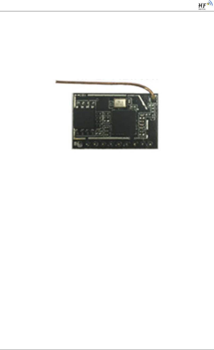
The HF-LPT120A is a fully self-contained small form-factor, single stream, 802.11b/g/n Wi-Fi module,
which provide a wireless interface to any equipment with a Serial/PWM interface for data transfer.HF-
LPT120A integrate MAC, baseband processor, RF transceiver with power amplifier in hardware and
all Wi-Fi protocol and configuration functionality and networking stack, in embedded firmware to make
a fully self-contained 802.11b/g/n Wi-Fi solution for a variety of applications.
The HF-LPT120A employs the world's lowest power consumption embedded architecture. It has been
optimized for all kinds of client applications in the home automation, smart grid, handheld device,
personal medical application and industrial control that have lower data rates, and transmit or receive
data on an infrequent basis.
The HF-LPT120A integrates all Wi-Fi functionality into a low-profile, 22mm x 13.5mm x 6mm module
package that can be easily mounted on main PCB with application specific circuits. Also, module
provides built-in antenna, external antenna option.
1.1.1 Device Features
Single stream Wi-Fi @ 2.4 GHz with support for WEP security mode as well as WPA/WPA2
Based on Self-developed High Cost Performance SOC
Includes all the protocol and configuration functions for Wi-Fi connectivity.
Support STA/AP Mode
Support Smart Link Function
Support Wireless and Remote Firmware Upgrade Function
Support External I-PEX or Internal PCB antenna connector options.
Compact surface mount module 22mm x 13.5mm x 6mm
Single supply – 3.3V operation.
FCC/CE Certified.
RoHS Compliant.
HF-LPT120A Low Power WiFi Module User Manual
Shanghai High-Flying Electronics Technology Co., Ltd(www.hi-flying.com) -9-
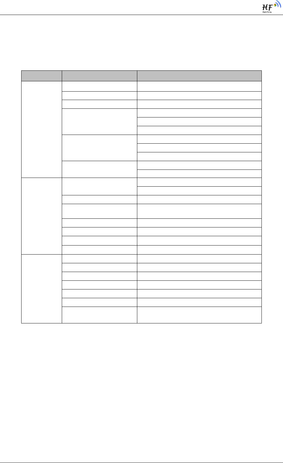
1.1.2 Device Paremeters
Table 1 HF-LPT120A Module Technical Specifications
Class Item Parameters
Wireless
Parameters
Certification FCC/CE
Wireless standard 802.11 b/
g
/n
Frequency range 2.412GHz-2.462GHz
Transmit Power
802.11b: +16 +/-2dBm (@11Mbps)
802.11g: +14 +/-2dBm (@54Mbps)
802.11n: +13 +/-2dBm (@HT20, MCS7)
Receiver Sensitivity
802.11b: -93 dBm (@11Mbps ,CCK)
802.11g: -85 dBm (@54Mbps, OFDM)
802.11n: -82 dBm (@HT20, MCS7)
Antenna Option External:I-PEX Connector
Internal:PCB Printed
A
ntenna
Hardware
Parameters
Data Interface UART
GPIO
Operating Voltage 2.95~3.6V
Operating Current Peak [Continuous TX]: ~280mA
A
verage. ~20mA
Operating Temp. -20℃-85℃
Storage Temp. -40℃-125℃
Dimensions and Size 22mm x 13.5mm x 6mm
External Interface 1x10, 2mm DIP
Software
Parameters
Network Type STA /AP
Security Mechanisms WEP/WPA-PSK/WPA2-PSK
Encryption WEP64/WEP128/TKIP/AES
Update Firmware Local Wireless, Remote
Customization Support customization
Network Protocol IPv4, TCP/UDP/HTTP
User Configuration AT+instruction set. Android/ iOS
Smart Link APP tools
1.1.3 Key Application
Remote equipment monitoring
Asset tracking and telemetry
Security
Industrial sensors and controls
Home automation
Medical devices
HF-LPT120A Low Power WiFi Module User Manual
Shanghai High-Flying Electronics Technology Co., Ltd(www.hi-flying.com) -10-
1.2. Hardware Introduction
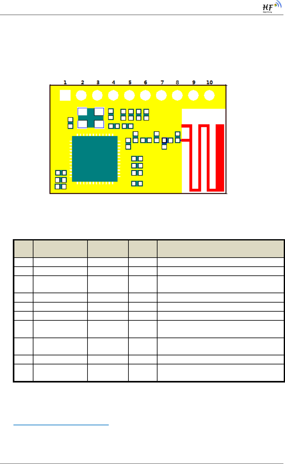
1.2.1. Pins Definition
Figure 1. HF-LPT120A Pins Map
Table 2 HF-LPT120A Pins Definition
Pin Description Net Name Signal
Type
Comments
1 Ground GND Power
2 +3.3V Power DVDD Power 3.3V@300m
A
3Restore
Configuration
nReload I/O,PU Can be configured as GPIO_2
Detailed functions see <Notes>
4 Module Reset EXT_RESETn I,PU “Low” effective reset input.
5 UART0 UART0_RX I GPIO_19
6 UART0 UART0_TX O,PU GPIO_20
7 GPIO_5 GPIO_5 I/O GPIO_5,UART1_TXD
UART1 Debug Output
8 GPIO_6 GPIO_6 I/O GPIO_6, UART1_RXD
UART1 Debug Input
9 GPIO_3 nReady I/O Can be configured as nReady,GPIO
10 GPIO_15 nLink I/O Can be configured as nLink,GPIO
Detailed functions see <Notes>
I—Input, O—Output,PU—Internal Pullup Resistor;I/O: Digital I/O;Power—Power
<Notes>
nReload Pin (Button) function:
1. When this pin is set to “low” during module boot up, the module will enter wireless
firmware and config upgrade mode. This mode is used for customer manufacture.

HF-LPT120A Low Power WiFi Module User Manual
Shanghai High-Flying Electronics Technology Co., Ltd(www.hi-flying.com) -11-
(See Appendix D to download software tools for customer batch configuration and
upgrade firmware during mass production)
2. After module is powered up, short press this button ( “Low” < 2s ) to make the
module go into “Smart Link “ config mode, waiting for APP to set password and
other information. (See Appendix D to download SmartLink APP)
3. After module is powered up, long press this button ( “Low” > 4s ) to make the
module recover to factory setting.
High-Flying strongly suggest customer fan out this pin to connector or button for
“Manufacture” and “ Smart Link” application.
nLink Pin (LED) function:
1. At wireless firmware and config upgrade mode , this LED used to indicate configure
and upgrade status.
2. At “Smart Link “ config mode, this LED used to indicate APP to finish setting.
3. At normal mode, it’s Wi-Fi link status indicator
High-Flying strongly suggest customer fan out this pin to LED.
1.2.2. Electrical Characteristics
Table 3 Absolute Maximum Ratings:
Parameter Condition Min. Typ. Max. Unit
Storage temperature range -40 125 °C
Maximum soldering temperature IPC/JEDEC J-STD-020 260 °C
Supply voltage 0 3.6 V
Voltage on any I/O pin 0 3.6 V
ESD (Human Body Model HBM) TAMB=25°C 2.5 KV
ESD (MM) TAMB=25°C 0.25 KV
Table 4 Power Supply & Power Consumption:
Parameter Condition Min. Typ. Max. Unit
Operating Supply voltage 2.95 3.3 3.6 V
Supply current, peak Continuous Tx 280 mA
Supply current, IEEE PS DTIM=100ms 20 mA
HF-LPT120A Low Power WiFi Module User Manual
Shanghai High-Flying Electronics Technology Co., Ltd(www.hi-flying.com) -12-
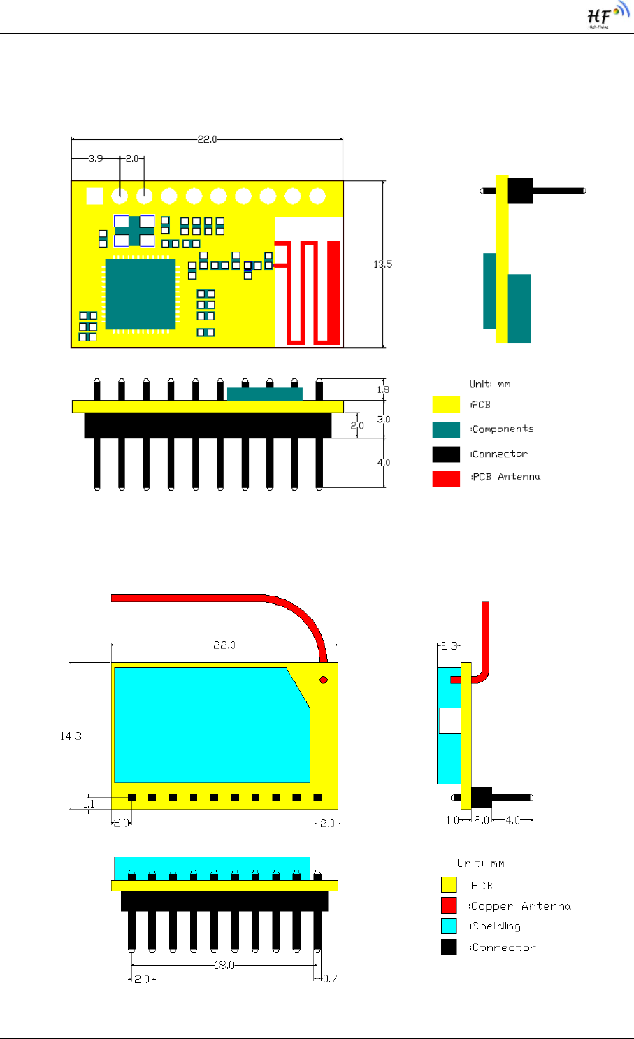
1.2.3. Mechanical Size
HF-LPT120A modules physical size (Unit: mm)as follows:
Figure 2. HF-LPT120A Mechanical Dimension
Figure 3. HF-LPT120AA Mechanical Dimension
HF-LPT120A Low Power WiFi Module User Manual
Shanghai High-Flying Electronics Technology Co., Ltd(www.hi-flying.com) -13-
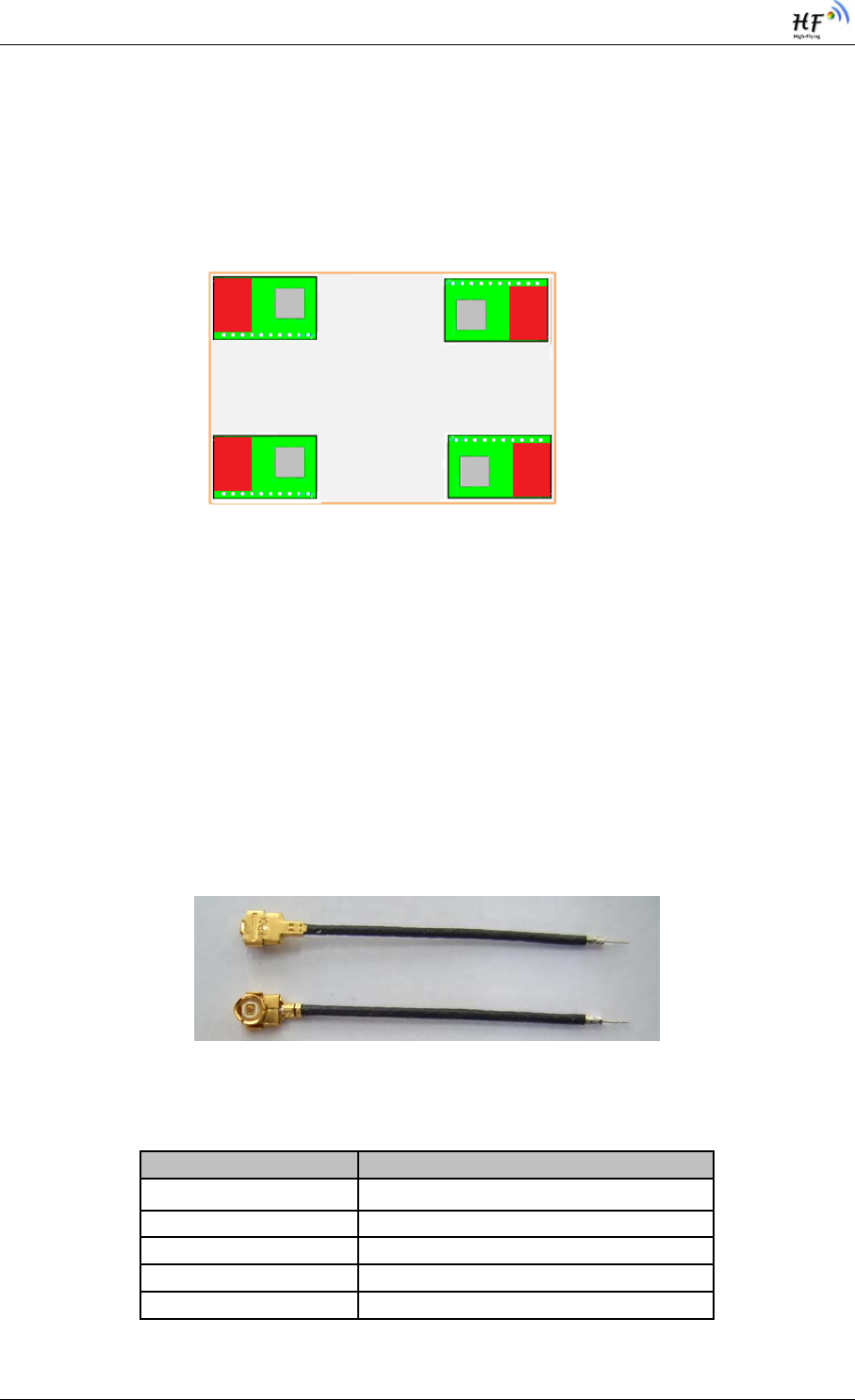
1.2.4. On-board PCB Antenna
HF-LPT120A module support internal on-board PCB antenna option. When customer select internal
antenna, you shall comply with following antenna design rules and module location suggestions:
For customer PCB, RED color region (8x10mm) can’t put componet or paste GND net;
Antenna must away from metal or high components at least 10mm;
Antenna can’t be shielded by any metal enclosure;
Figure 4. Suggested Module Placement Region
High-Flying suggest HF-LPB100 module better locate in following region at customer board, which to
reduce the effect to antenna and wireless signal, and better consult High-Flying technical people when
you structure your module placement and PCB layout.
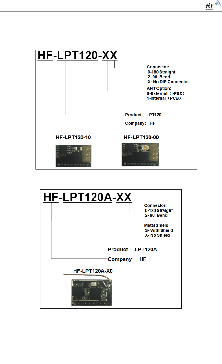
1.2.5. External Antenna
HF-LPT120A supports two way of external antenna as the following picture show, The I-PEX interface
or the PAD interface(remove the I-PEX connector). The user may choose one of them. If user select
external antenna, HF-LPT120A modules must be connected to the 2.4G antenna according to IEEE
802.11b/g/n standards.
The antenna parameters required as follows:
Figure 5. HF-LPT120A External Antenna picture
Table 5 HF-LPT120A External Antenna Parameters
Item Parameters
Frequency range 2.4~2.5GHz
Impedance 50 Ohm
VSWR 2 (Max)
Return Loss -10dB (Max)
Connector Type I-PEX or populate directly
HF-LPT120A Low Power WiFi Module User Manual
Shanghai High-Flying Electronics Technology Co., Ltd(www.hi-flying.com) -14-
1.2.6. Order Information
Base on customer detailed requirement, HF-LPT120A series modules provide different variants and
physical type for detailed application.
Figure 6. HF-LPT120A Order Information
Figure 7. HF-LPT120AA Order Information
HF-LPT120A Low Power WiFi Module User Manual
Shanghai High-Flying Electronics Technology Co., Ltd(www.hi-flying.com) -15-
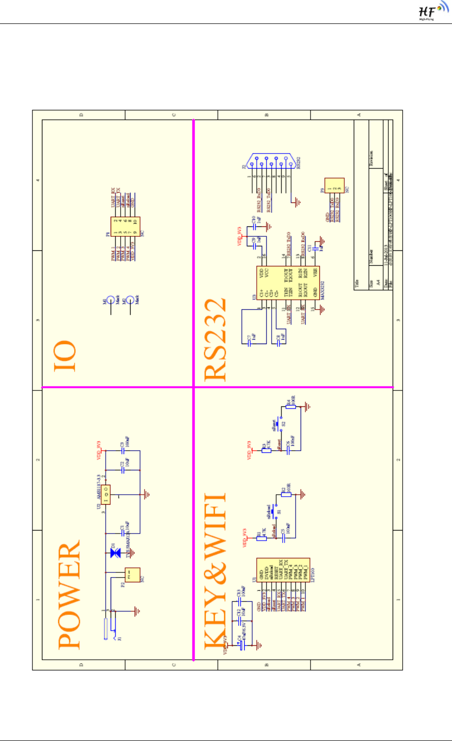
APPENDIX A: HW REFERENCE DESIGN
Detailed HF-LPT120A Evluation Board design source files, pls access High-Flying web download
page or contact with High-Flying technical support people to acquire.

HF-LPT120A Low Power WiFi Module User Manual
Shanghai High-Flying Electronics Technology Co., Ltd(www.hi-flying.com) -16-
APPENDIX B: HTTP PROTOCOL TRANSFER
HF-LPB120 module support http data transfer in command mode. If any detailed HTTP protocol,
contact us and we may support customization.
B.1. HTTP AT command(Reserved)
B.1.1 AT+HTTPURL
Function:Set /Query HTTP server IP address and Port Number.
Format:
Query Operation
AT+HTTPURL<CR>
+ok=<IP,Port><CR><LF><CR><LF>
Set Operation
AT+HTTPURL=<IP,Port><CR>
+ok<CR><LF><CR><LF>
Parameters:
IP:IP address.
Port:Port number.
B.1.2 AT+HTTPTP
Function:Set /Query HTTP request type
Format:
Query Operation
AT+HTTPTP<CR>
+ok=<Type><CR><LF><CR><LF>
Set Operation
AT+HTTPTP=<Type><CR>
+ok<CR><LF><CR><LF>
Parameters:
Type:GET(default) or POST。
B.1.3 AT+HTTPPH
Function:Set/Query HTTP protocol header path.
Format:
Query Operation
AT+HTTPPH<CR>
+ok=<Path><CR><LF><CR><LF>
Set Operation
AT+HTTPPH=<Path><CR>
+ok<CR><LF><CR><LF>
Parameters:

HF-LPT120A Low Power WiFi Module User Manual
Shanghai High-Flying Electronics Technology Co., Ltd(www.hi-flying.com) -17-
Path:Max length is 50 bytes.
B.1.4 AT+HTTPCN
Function:Set/Query Connection of HTTP protocol header
Format:
Query Operation
AT+HTTPCN<CR>
+ok=<Connection><CR><LF><CR><LF>
Set Operation
AT+HTTPCN=<Connection><CR>
+ok<CR><LF><CR><LF>
Parameters:
Connection:Max length is 20 bytes.
B.1.5 AT+HTTPUA
Function:Set/Query User-Agent of HTTP protocol header.
Format:
Query Operation
AT+HTTPUA<CR>
+ok=<Parameter><CR><LF><CR><LF>
Set Operation
AT+HTTPUA=<Parameter><CR>
+ok<CR><LF><CR><LF>
Parameters:
Parameter:Max length is 20 bytes.
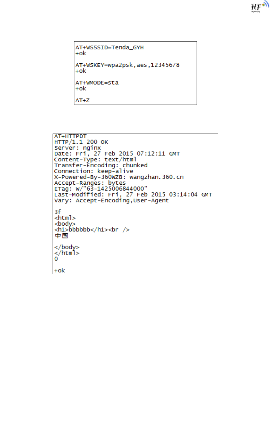
B.1.6 AT+HTTPDT
Function: Send HTTP request or data.
Format:
Set Operation
AT+HTTPDT=<Data><CR>
+ok<CR><LF><CR><LF>
Parameters:
Data:HTTP request data, send AT+HTTPDT directly if no data to be sent.
B.2. HTTP Example
HTTP parameter settings are as follows:
AT+HTTPURL=192.168.1.1,80 Set HTTP server address and port
AT+HTTPTP=POST Set HTTP request type
AT+HTTPPH=/abcd Set HTTP protocol header path
AT+HTTPCN= keep-alive Set HTTP Connection area
AT+HTTPUA= lwip1.3.2 Set HTTP User-Agent area
HF-LPT120A Low Power WiFi Module User Manual
Shanghai High-Flying Electronics Technology Co., Ltd(www.hi-flying.com) -18-
If send “AT+HTTPDT”, the data packet will be sent as the following instance including the two
new line:
POST /abcd HTTP/1.1
Connection:keep-alive
User-Agent:lwip1.3.2
Content-Length:0
Host:192.168.0.127:8999
If send AT+HTTPDT=abcd, the data packet will be sent as the following instance:
POST /abcd HTTP/1.1
Connection:keep-alive
User-Agent:lwip1.3.2
Content-Length:4
Host:192.168.0.127:8999
abcd
The data received from HTTP server will be output to serial port and end with “+ok”.
If the module hasn’t received data from HTTP server for 5 second, it will cut the TCP link with
HTTP server.
B.3. Sending HTTP Raw Data in Throughput Mode(Recommend)
Step 1、Configure HTTP server information
Step 2、Configure module connecting to router AP and reboot.
Step 3、Sending HTTP raw data via UART, end the data with<CR><LF><CR><LF>
HF-LPT120A Low Power WiFi Module User Manual
Shanghai High-Flying Electronics Technology Co., Ltd(www.hi-flying.com) -19-
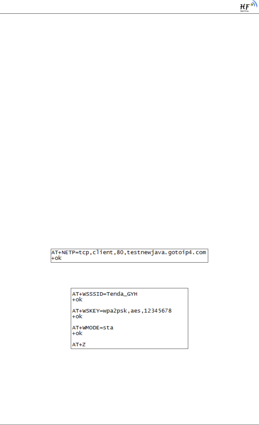
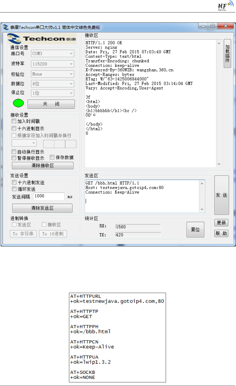
B.4. Sending HTTP Request By AT Command
Step 1、Configure HTTP AT command. SOCKB must set as None.
HF-LPT120A Low Power WiFi Module User Manual
Shanghai High-Flying Electronics Technology Co., Ltd(www.hi-flying.com) -20-
Step 2、Configure module connecting to router AP and reboot.
Step 3、Send HTTP request

HF-LPT120A Low Power WiFi Module User Manual
Shanghai High-Flying Electronics Technology Co., Ltd(www.hi-flying.com) -21-
APPENDIX C:REFERENCES
C.1.High-Flying Mass Production Tool
Download Address:http://www.hi-flying.com/download_detail_dc/&downloadsId=07bc0a59-0a0d-
4fb4-a5e5-c3403f09ab08&comp_stats=comp-FrontDownloads_list01-dc.html
C.2.SmartLink APP V7 Config Tool
IOS Platform : http://www.hi-flying.com/download_detail_dc/&downloadsId=5cc0c241-77b4-48c1-bf9c-
2ad2954b3b50&comp_stats=comp-FrontDownloads_list01-dc.html
Android Platform: http://www.hi-flying.com/download_detail_dc/&downloadsId=9a0d0290-477e-4184-
8636-18510eaed6b1&comp_stats=comp-FrontDownloads_list01-dc.html
C.3.EVK Quick Start Guide
Download Address:http://www.hi-flying.com/download_detail_dc/&downloadsId=b545c662-4ec7-
49a4-aea4-e0997f062a62&comp_stats=comp-FrontDownloads_list01-dc.html
C.4.Module Upgrade
Download Address:http://www.hi-flying.com/download_detail_fir/&downloadsId=825a57bc-5535-
4f07-bf23-6f5e7ad2700b.html

HF-LPT120A Low Power WiFi Module User Manual
Shanghai High-Flying Electronics Technology Co., Ltd(www.hi-flying.com) -22-
APPENDIX D: CONTACT INFORMATION
------------------------------------------------------------------------------------------------------------
Address: Room 1002,Building 1,No.3000,Longdong Avenue,Pudong New
Area,Shanghai,China,201203
Web: www.hi-flying.com
Service Online: 400-189-3108/18616078755
Sales Contact: sales@hi-flying.com
-----------------------------------------------------------------------------------------------------------
For more information about High-Flying modules, applications, and solutions, please visit our web site
http://www.hi-flying.com/en/
<END OF DOCUMENT>
© Copyright High-Flying, May, 2011
The information disclosed herein is proprietary to High-Flying and is not to be used by or disclosed to unauthorized persons
without the written consent of High-Flying. The recipient of this document shall respect the security status of the information.
The master of this document is stored on an electronic database and is “write-protected” and may be altered only by
authorized persons at High-Flying. Viewing of the master document electronically on electronic database ensures access to
the current issue. Any other copies must be regarded as uncontrolled copies.