Hilberling RF Laboratories HPA8000B-54 Amateur Radio Power Amplifier 1 kW / 1.8 - 54 MHz User Manual HF VHF Transceiver
Hilberling GmbH RF Laboratories Amateur Radio Power Amplifier 1 kW / 1.8 - 54 MHz HF VHF Transceiver
UserManual.wiki
>
Hilberling RF Laboratories
>
HPA8000B 54 User Manual
User Manual
Navigation menu
Upload a User Manual
Namespaces
Wiki Guide
HTML
PDF
Info
Views
User Manual
Discussion / Help
Navigation
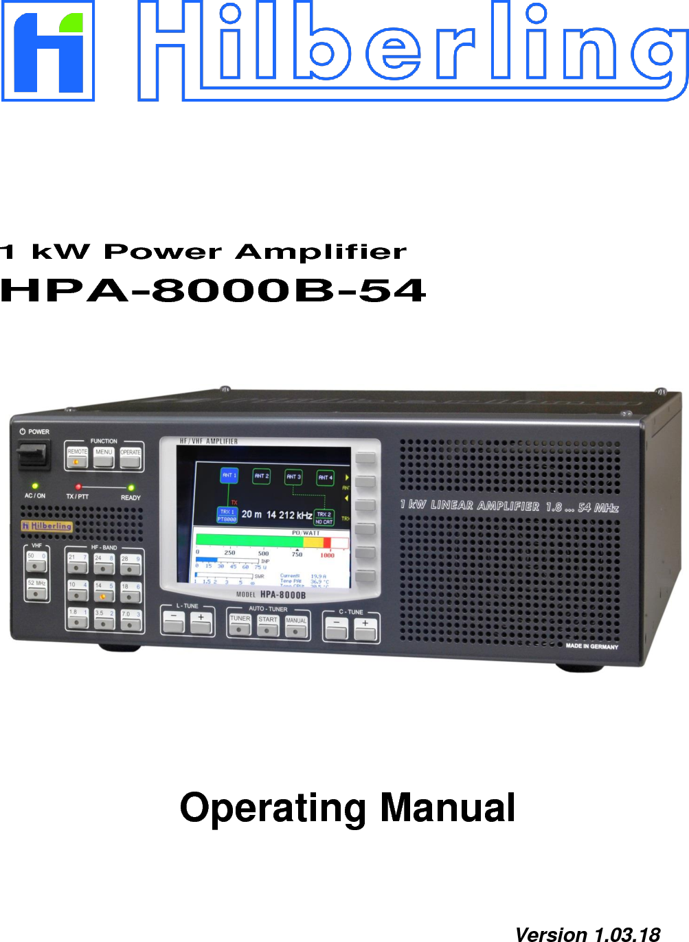

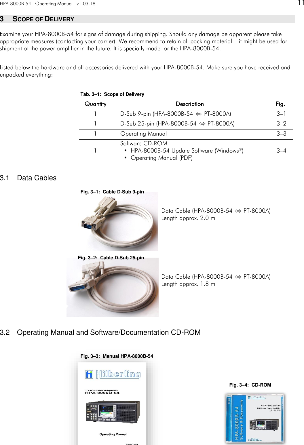
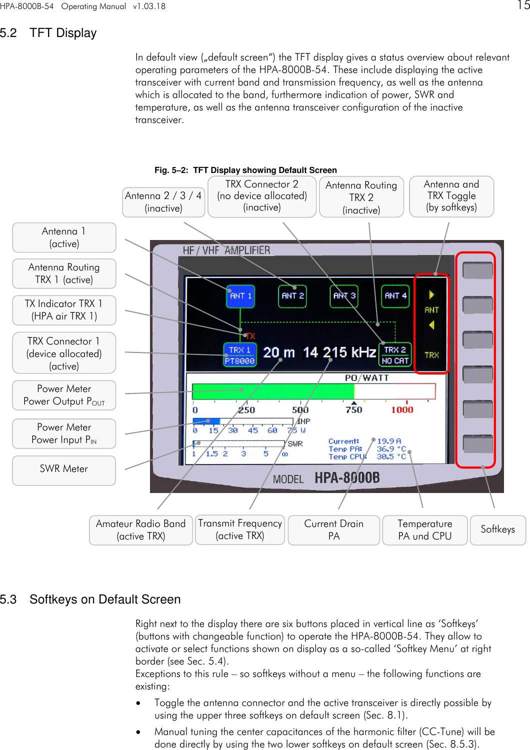

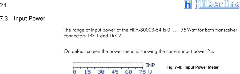
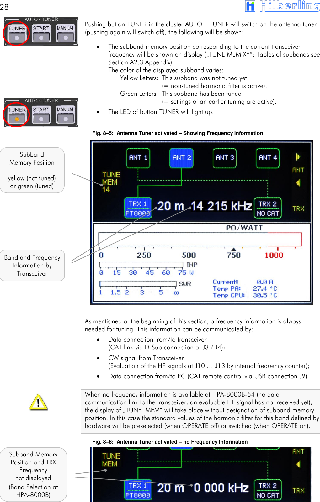
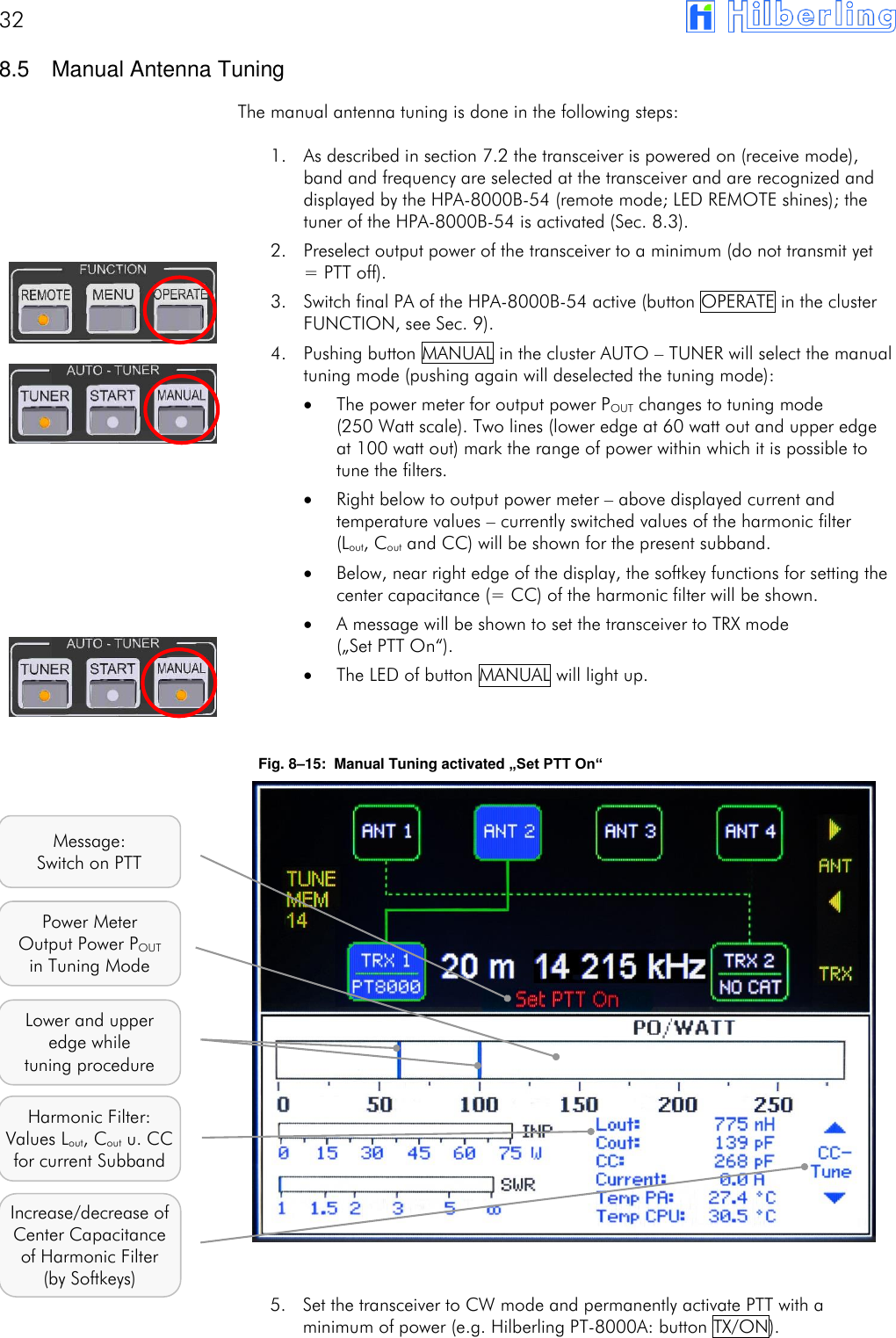
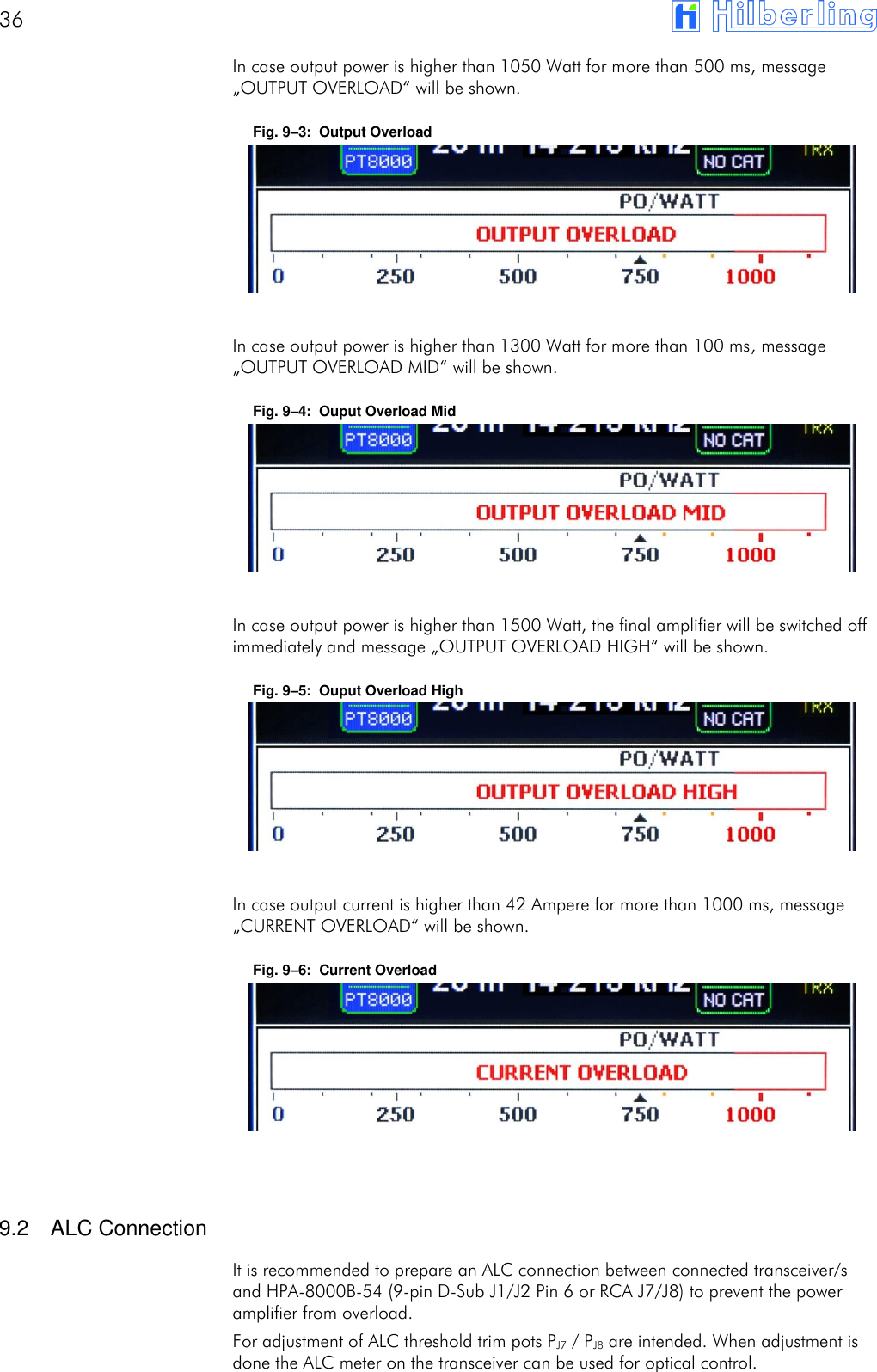

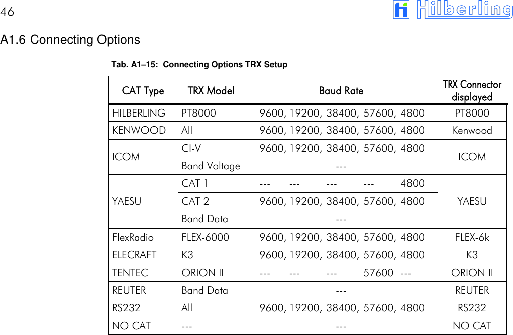
![40 A1.3 Subbands Antenna Tuning Tab. A1–4: Subbands 160m Frequency [kHz] TUNE MEM [1] [2] [3] [4] [5] [6] [7] [8] [9] Lower 1780 1784 1788 1792 1796 1800 1804 1808 1812 Middle 1782 1786 1790 1794 1798 1802 1806 1810 1814 Upper 1784 1788 1792 1796 1800 1804 1808 1812 1816 TUNE MEM [10] [11] [12] [13] [14] [15] [16] [17] [18] [19] Lower 1816 1820 1824 1828 1832 1836 1840 1844 1848 1852 Middle 1818 1822 1826 1830 1834 1838 1842 1846 1850 1854 Upper 1820 1824 1828 1832 1836 1840 1844 1848 1852 1856 TUNE MEM [20] [21] [22] [23] [24] [25] [26] [27] [28] [29] Lower 1856 1860 1864 1868 1872 1876 1880 1884 1888 1892 Middle 1858 1862 1866 1870 1874 1878 1882 1886 1890 1894 Upper 1860 1864 1868 1872 1876 1880 1884 1888 1892 1896 TUNE MEM [30] [31] [32] [33] [34] [35] [36] [37] [38] [39] Lower 1896 1900 1904 1908 1912 1916 1920 1924 1928 1932 Middle 1898 1902 1906 1910 1914 1918 1922 1926 1930 1934 Upper 1900 1904 1908 1912 1916 1920 1924 1928 1932 1936 TUNE MEM [40] [41] [42] [43] [44] [45] [46] [47] [48] [49] Lower 1936 1940 1944 1948 1952 1956 1960 1964 1968 1972 Middle 1938 1942 1946 1950 1954 1958 1962 1966 1970 1974 Upper 1940 1944 1948 1952 1956 1960 1964 1968 1972 1976 TUNE MEM [50] [51] [52] [53] [54] [55] [56] [57] [58] [59] Lower 1976 1980 1984 1988 1992 1996 2000 2004 2008 2012 Middle 1978 1982 1986 1990 1994 1998 2002 2006 2010 2014 Upper 1980 1984 1988 1992 1996 2000 2004 2008 2012 2016 TUNE MEM [60] Lower 2016 Middle 2018 Upper 2020 Number of Subbands:60 Increment: 4 kHz](https://usermanual.wiki/Hilberling-RF-Laboratories/HPA8000B-54/User-Guide-3368311-Page-40.png)
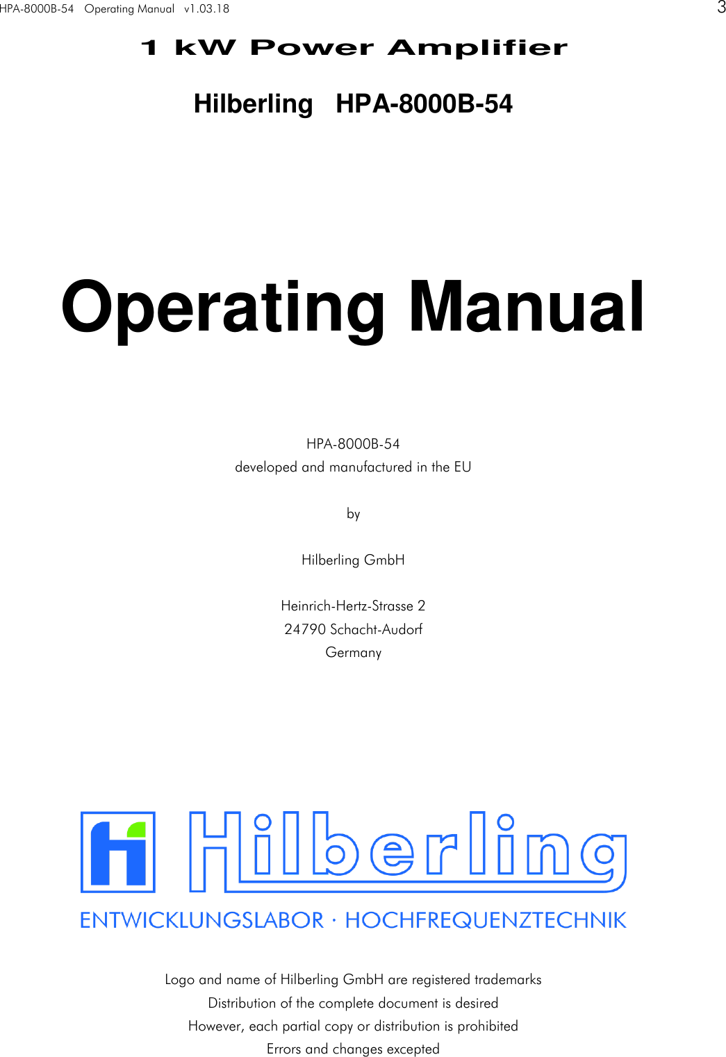
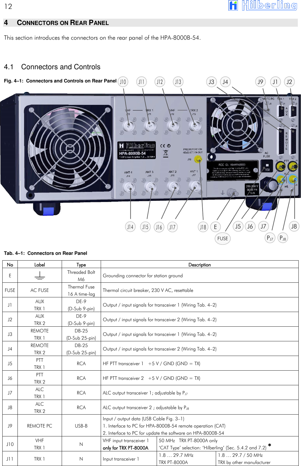
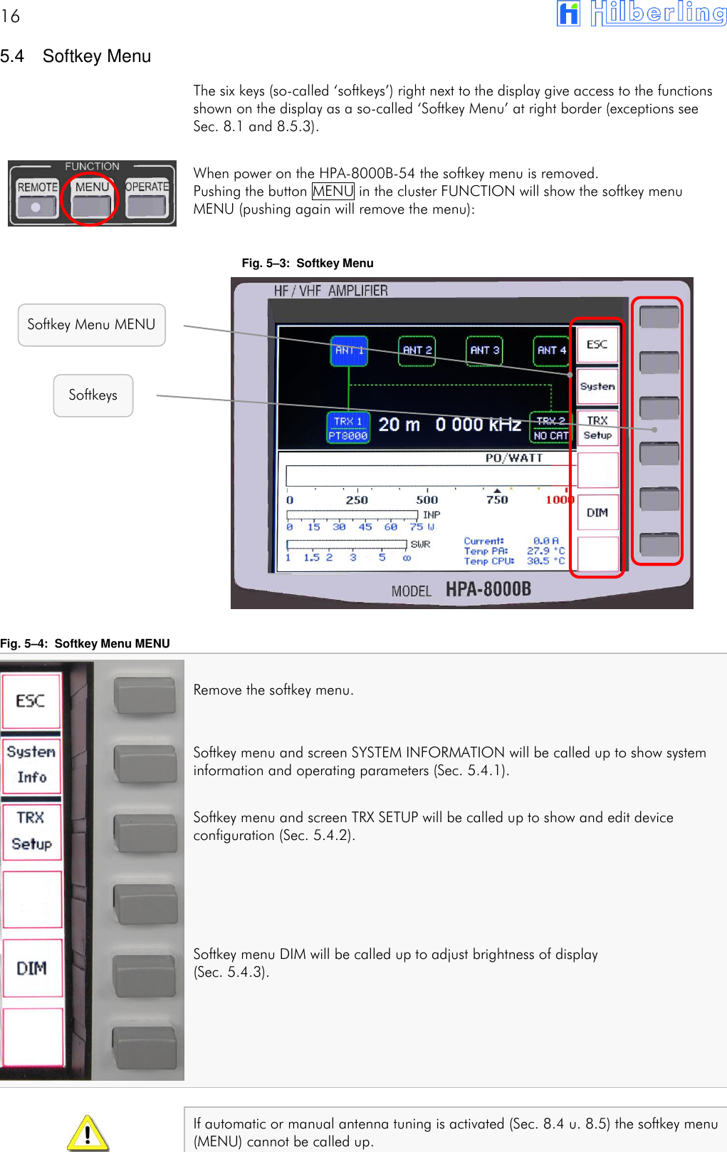
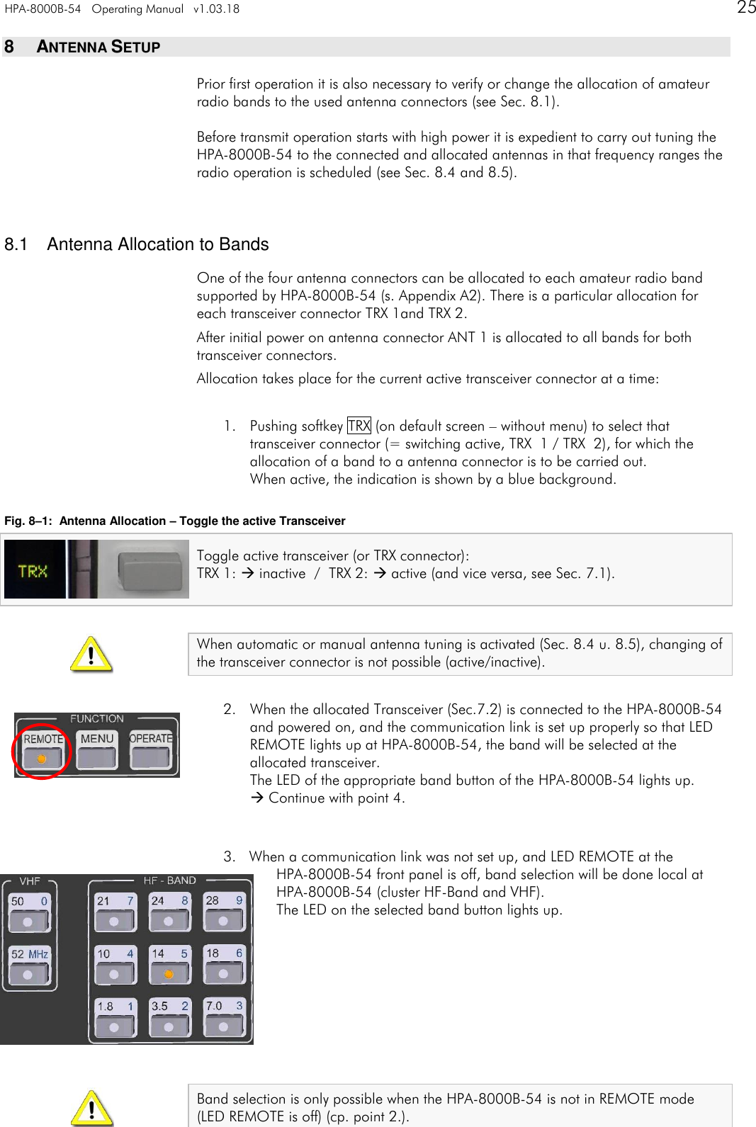
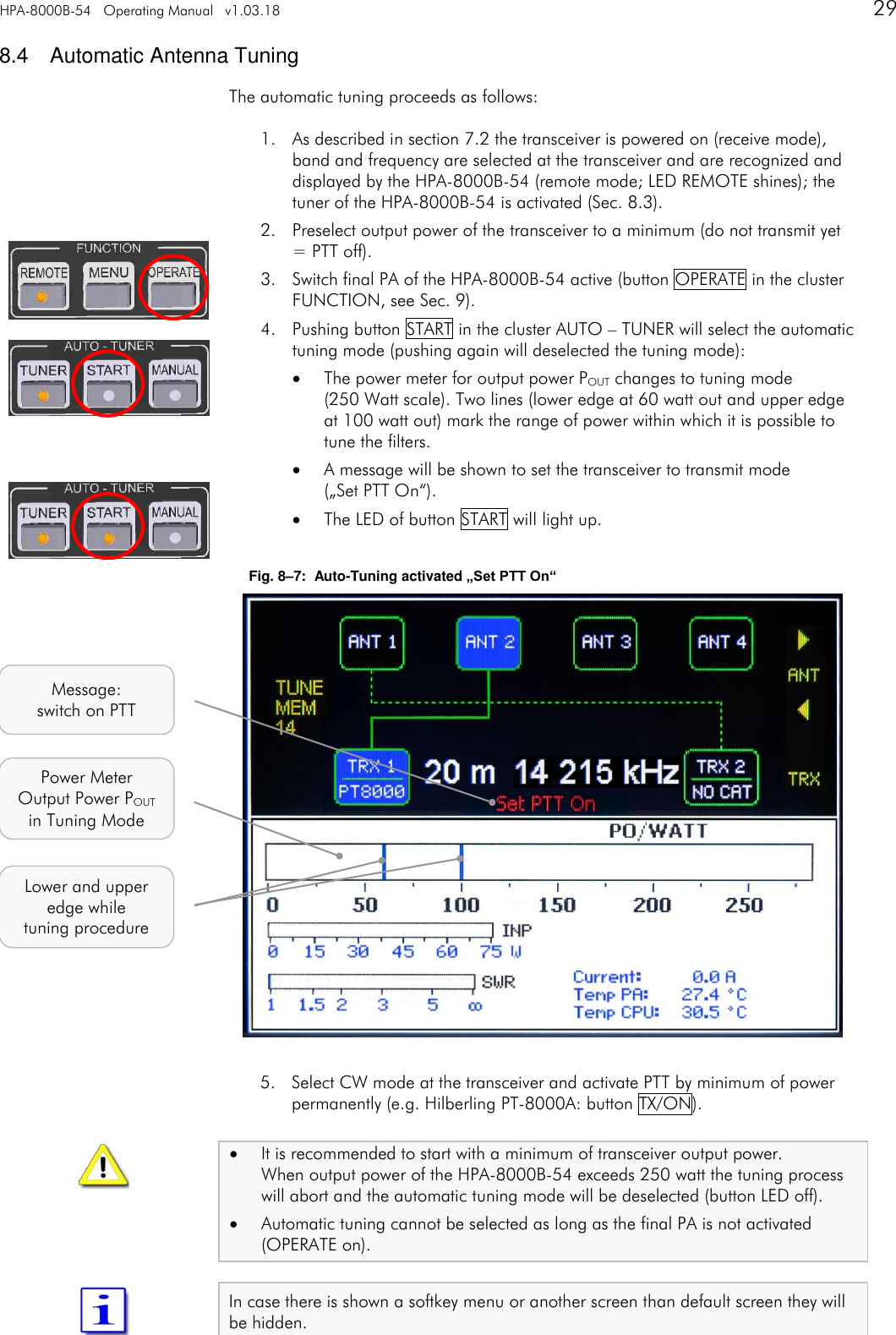
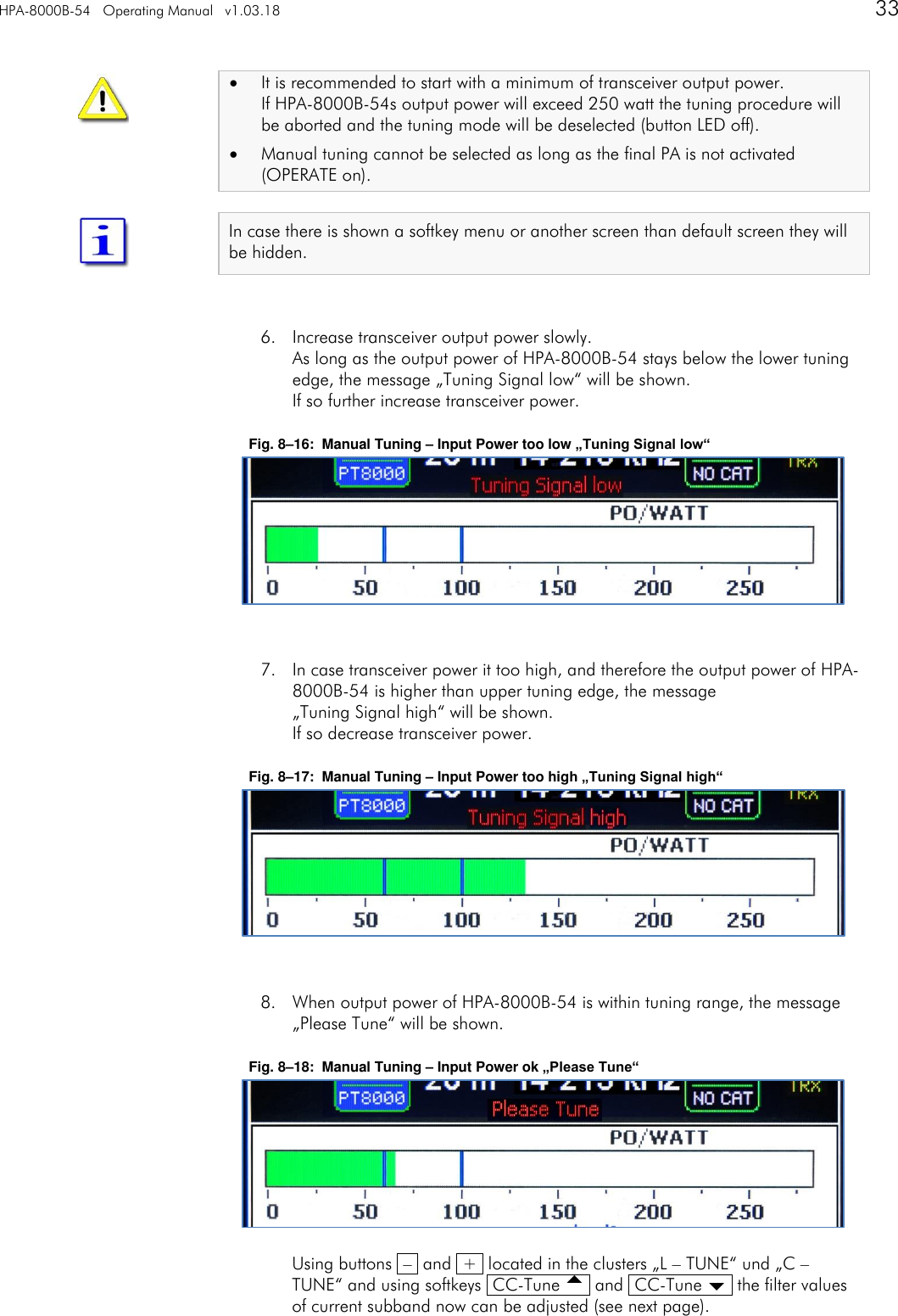
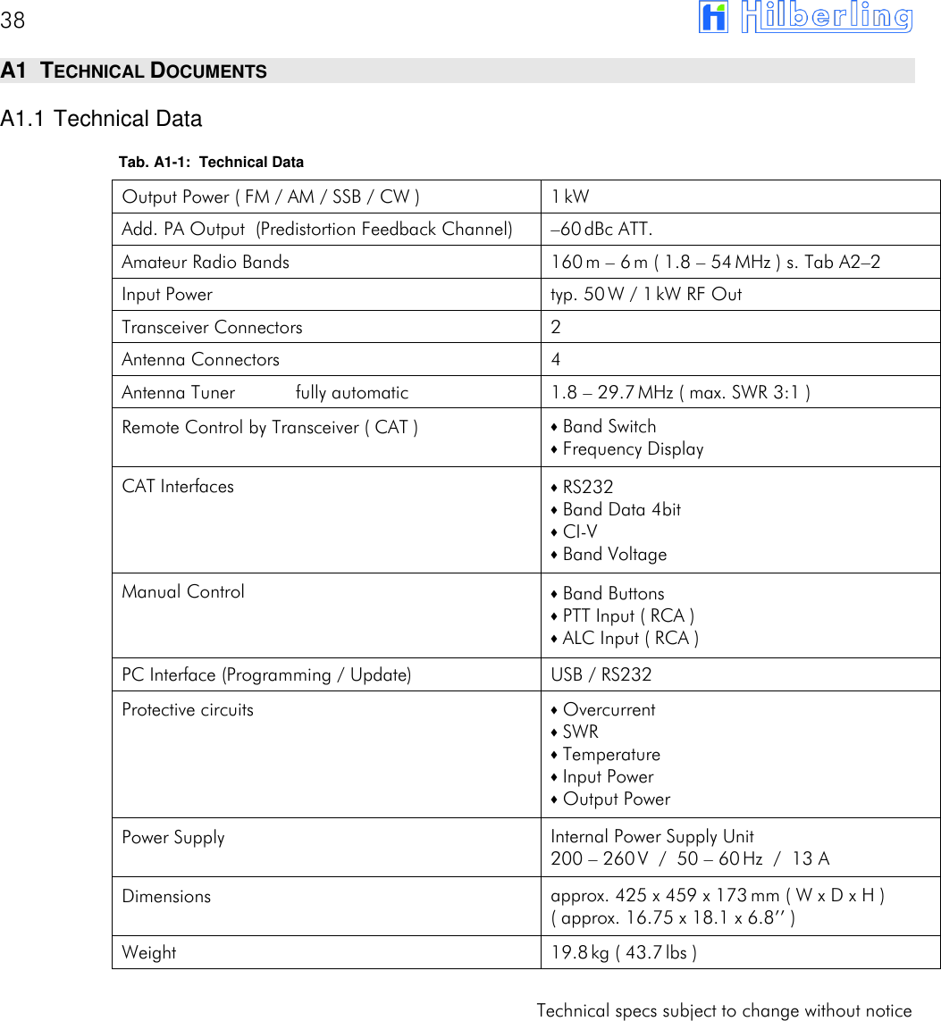
![HPA-8000B-54 Appendix A2 v1.03.18 41 Tab. A1–5: Subbands 80m Frequency [kHz] TUNE MEM [1] [2] [3] [4] [5] [6] [7] [8] [9] Lower 3460 3470 3480 3490 3500 3510 3520 3530 3540 Middle 3465 3475 3485 3495 3505 3515 3525 3535 3545 Upper 3470 3480 3490 3500 3510 3520 3530 3540 3550 TUNE MEM [10] [11] [12] [13] [14] [15] [16] [17] [18] [19] Lower 3550 3560 3570 3580 3590 3600 3610 3620 3630 3640 Middle 3555 3565 3575 3585 3595 3605 3615 3625 3635 3645 Upper 3560 3570 3580 3590 3600 3610 3620 3630 3640 3650 TUNE MEM [20] [21] [22] [23] [24] [25] [26] [27] [28] [29] Lower 3650 3660 3670 3680 3690 3700 3710 3720 3730 3740 Middle 3655 3665 3675 3685 3695 3705 3715 3725 3735 3745 Upper 3660 3670 3680 3690 3700 3710 3720 3730 3740 3750 TUNE MEM [30] [31] [32] [33] [34] [35] [36] [37] [38] [39] Lower 3750 3760 3770 3780 3790 3800 3810 3820 3830 3840 Middle 3755 3765 3775 3785 3795 3805 3815 3825 3835 3845 Upper 3760 3770 3780 3790 3800 3810 3820 3830 3840 3850 TUNE MEM [40] [41] [42] [43] [44] [45] [46] [47] [48] [49] Lower 3850 3860 3870 3880 3890 3900 3910 3920 3930 3940 Middle 3855 3865 3875 3885 3895 3905 3915 3925 3935 3945 Upper 3860 3870 3880 3890 3900 3910 3920 3930 3940 3950 TUNE MEM [50] [51] [52] [53] [54] [55] [56] [57] [58] Lower 3950 3960 3970 3980 3990 4000 4010 4020 4030 Middle 3955 3965 3975 3985 3995 4005 4015 4025 4035 Upper 3960 3970 3980 3990 4000 4010 4020 4030 4040 Number of Subbands:58 Increment: 10 kHz](https://usermanual.wiki/Hilberling-RF-Laboratories/HPA8000B-54/User-Guide-3368311-Page-41.png)
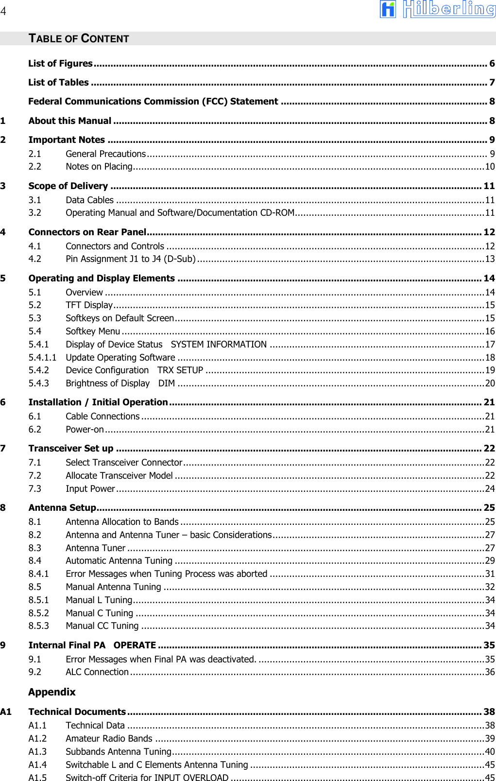
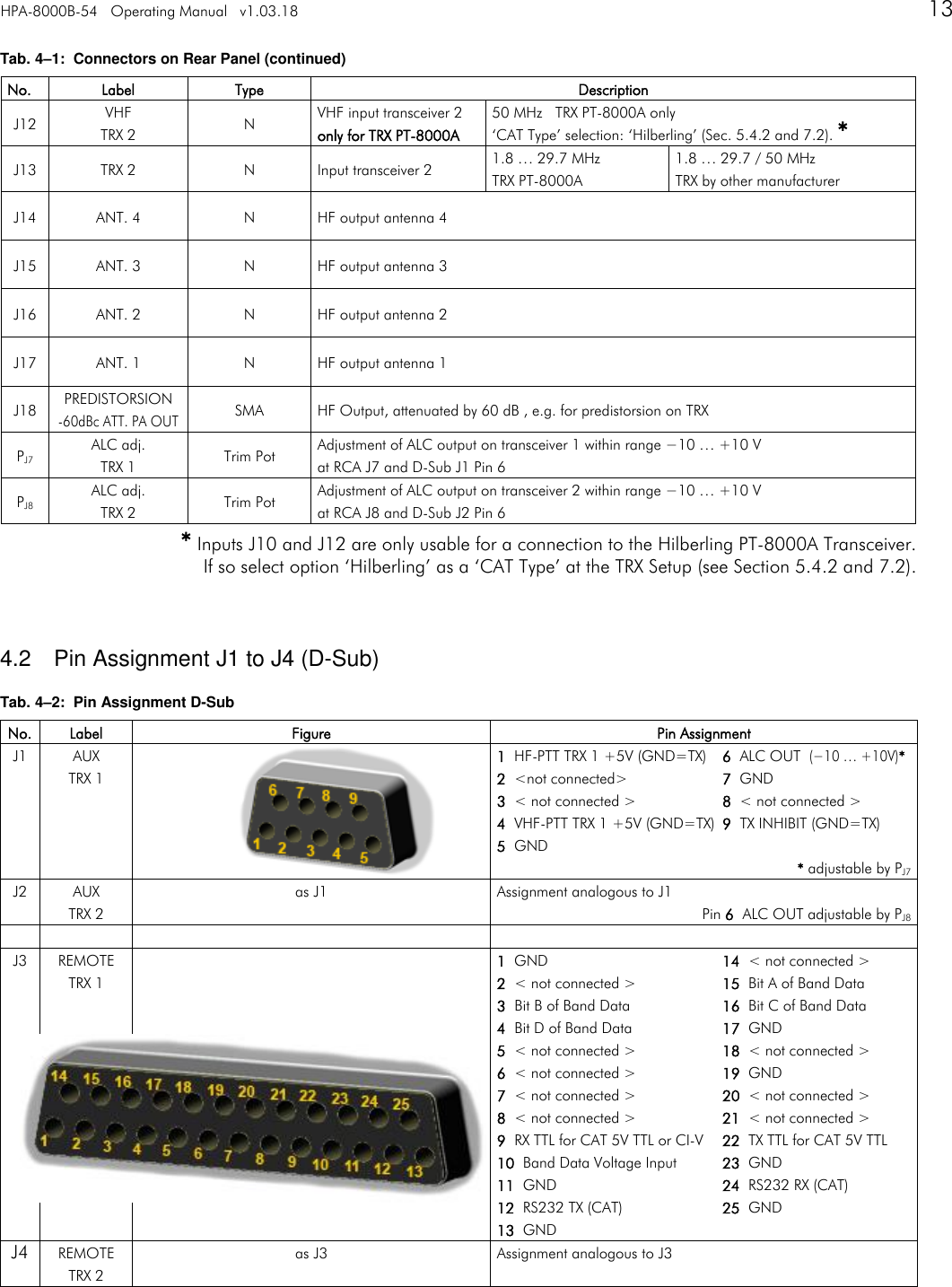
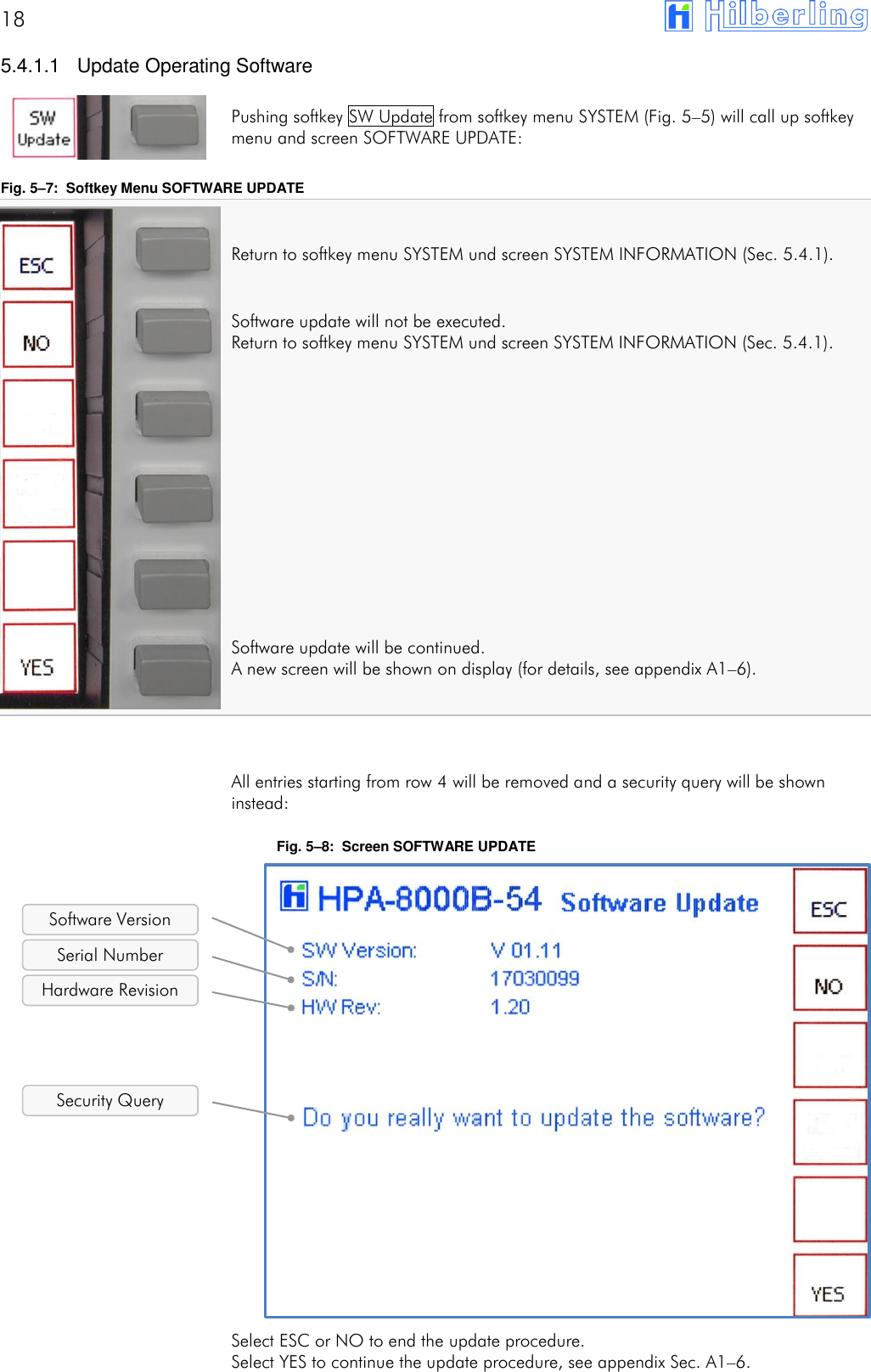
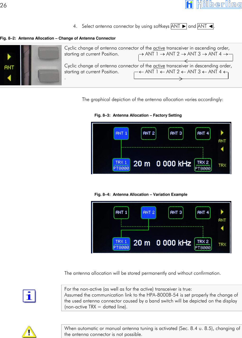
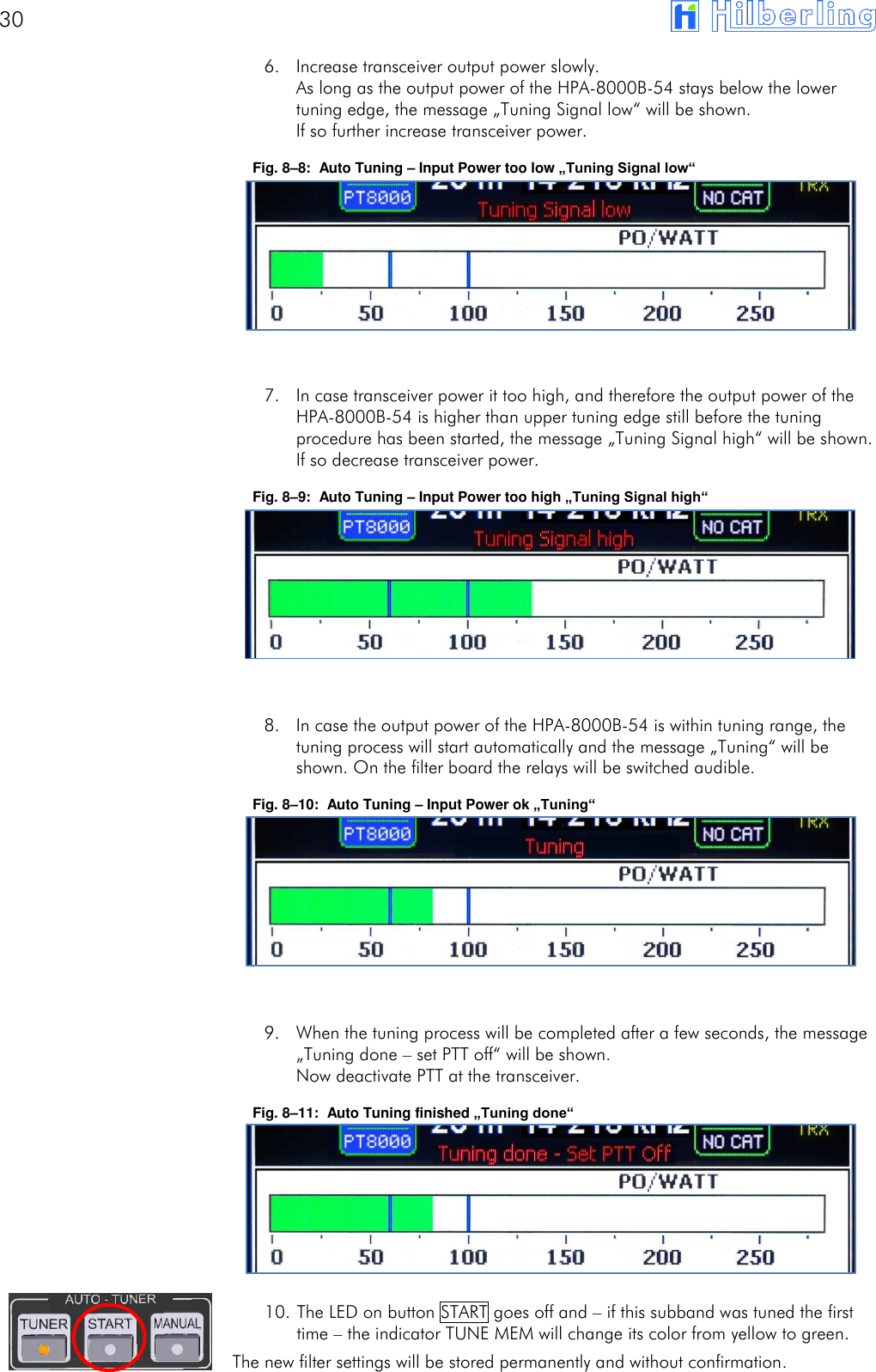
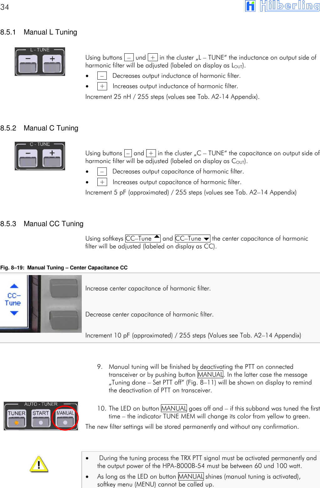
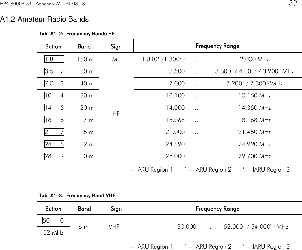
![42 Tab. A1–6: Subbands 40m Frequency [kHz] TUNE MEM [1] [2] [3] [4] [5] [6] [7] [8] [9] Lower 6950 6960 6970 6980 6990 7000 7010 7020 7030 Middle 6955 6965 6975 6985 6995 7005 7015 7025 7035 Upper 6960 6970 6980 6990 7000 7010 7020 7030 7040 TUNE MEM [10] [11] [12] [13] [14] [15] [16] [17] [18] [19] Lower 7040 7050 7060 7070 7080 7090 7100 7110 7120 7130 Middle 7045 7055 7065 7075 7085 7095 7105 7115 7125 7135 Upper 7050 7060 7070 7080 7090 7100 7110 7120 7130 7140 TUNE MEM [20] [21] [22] [23] [24] [25] [26] [27] [28] [29] Lower 7140 7150 7160 7170 7180 7190 7200 7210 7220 7230 Middle 7145 7155 7165 7175 7185 7195 7205 7215 7225 7235 Upper 7150 7160 7170 7180 7190 7200 7210 7220 7230 7240 TUNE MEM [30] [31] [32] [33] [34] [35] [36] [37] [38] [39] Lower 7240 7250 7260 7270 7280 7290 7300 7310 7320 7330 Middle 7245 7255 7265 7275 7285 7295 7305 7315 7325 7335 Upper 7250 7260 7270 7280 7290 7300 7310 7320 7330 7340 TUNE MEM [40] Lower 7340 Middle 7345 Upper 7350 Number of Subbands:40 Increment: 10 kHz Tab. A1–7: Subbands 30m Frequency [kHz] TUNE MEM [1] [2] [3] [4] [5] [6] [7] [8] [9] Lower 10050 10070 10090 10110 10130 10150 10170 10190 10210 Middle 10060 10080 10100 10120 10140 10160 10180 10200 10220 Upper 10070 10090 10110 10130 10150 10170 10190 10210 10230 TUNE MEM [10] Lower 10230 Middle 10240 Upper 10250 Number of Subbands:10 Increment: 20 kHz](https://usermanual.wiki/Hilberling-RF-Laboratories/HPA8000B-54/User-Guide-3368311-Page-42.png)
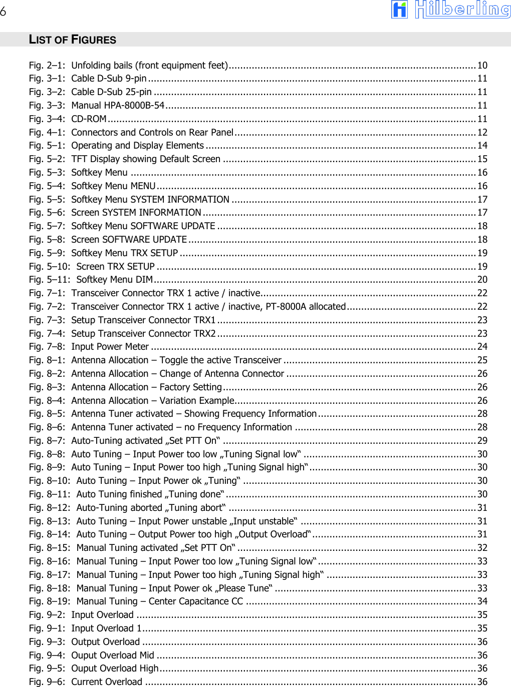
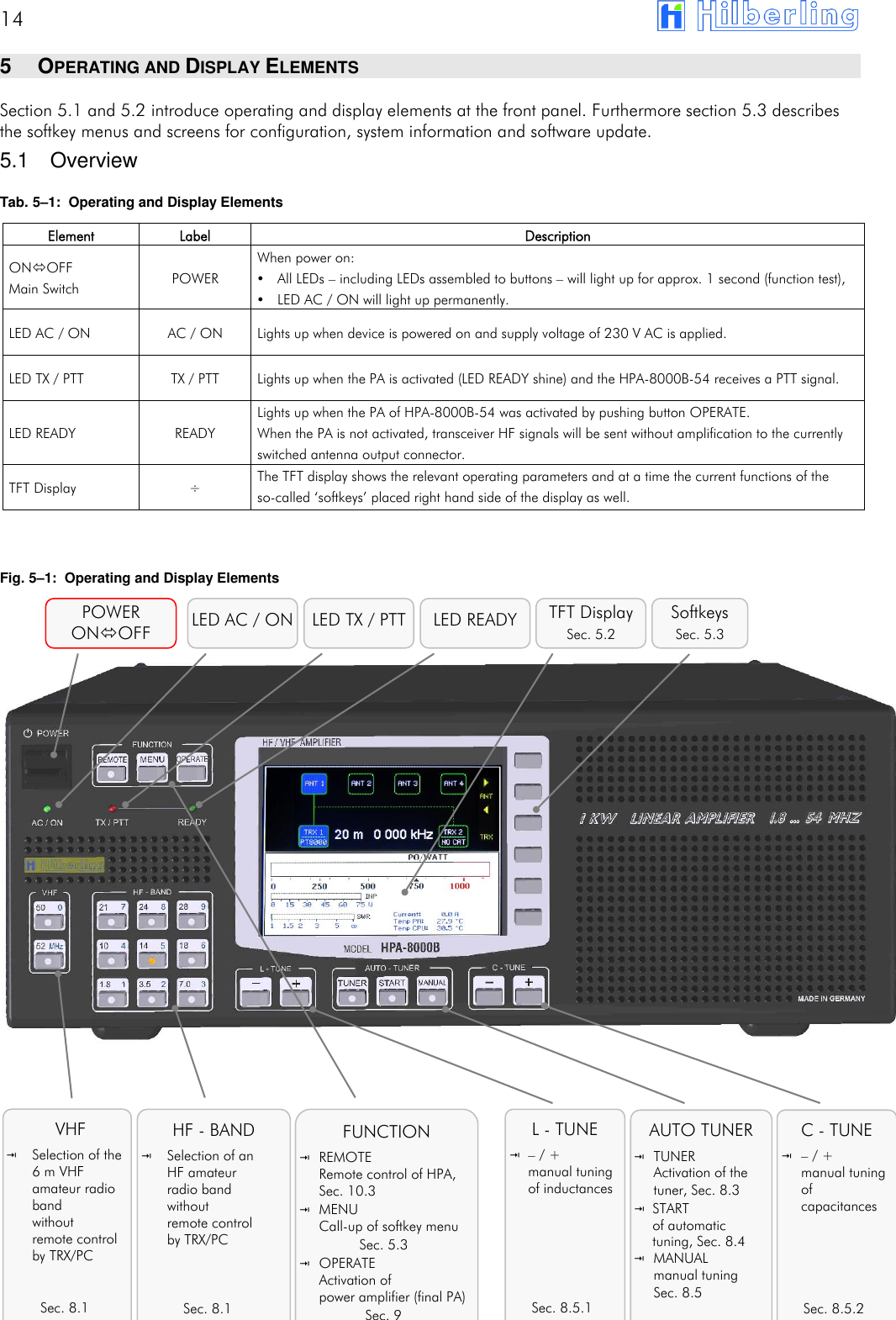
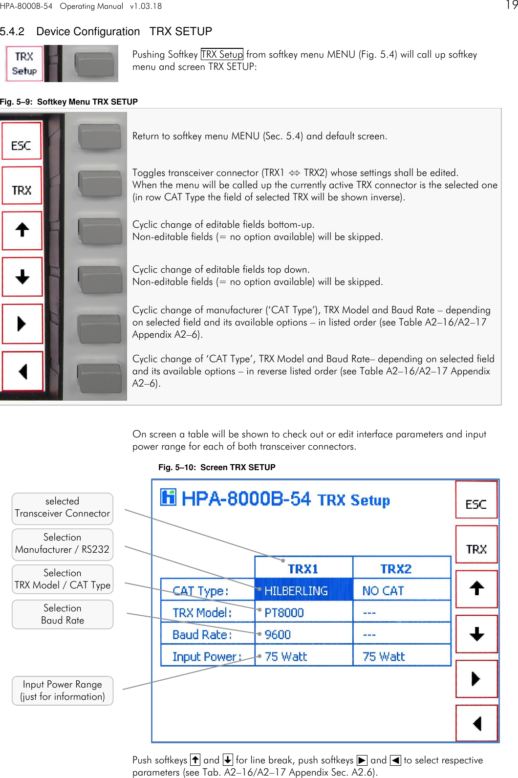
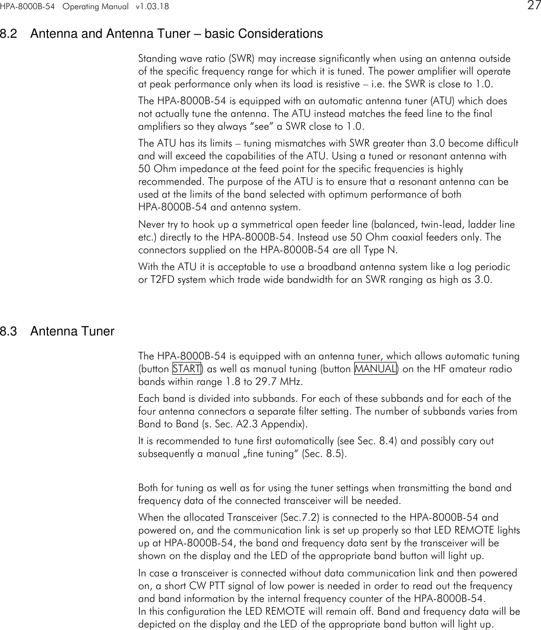
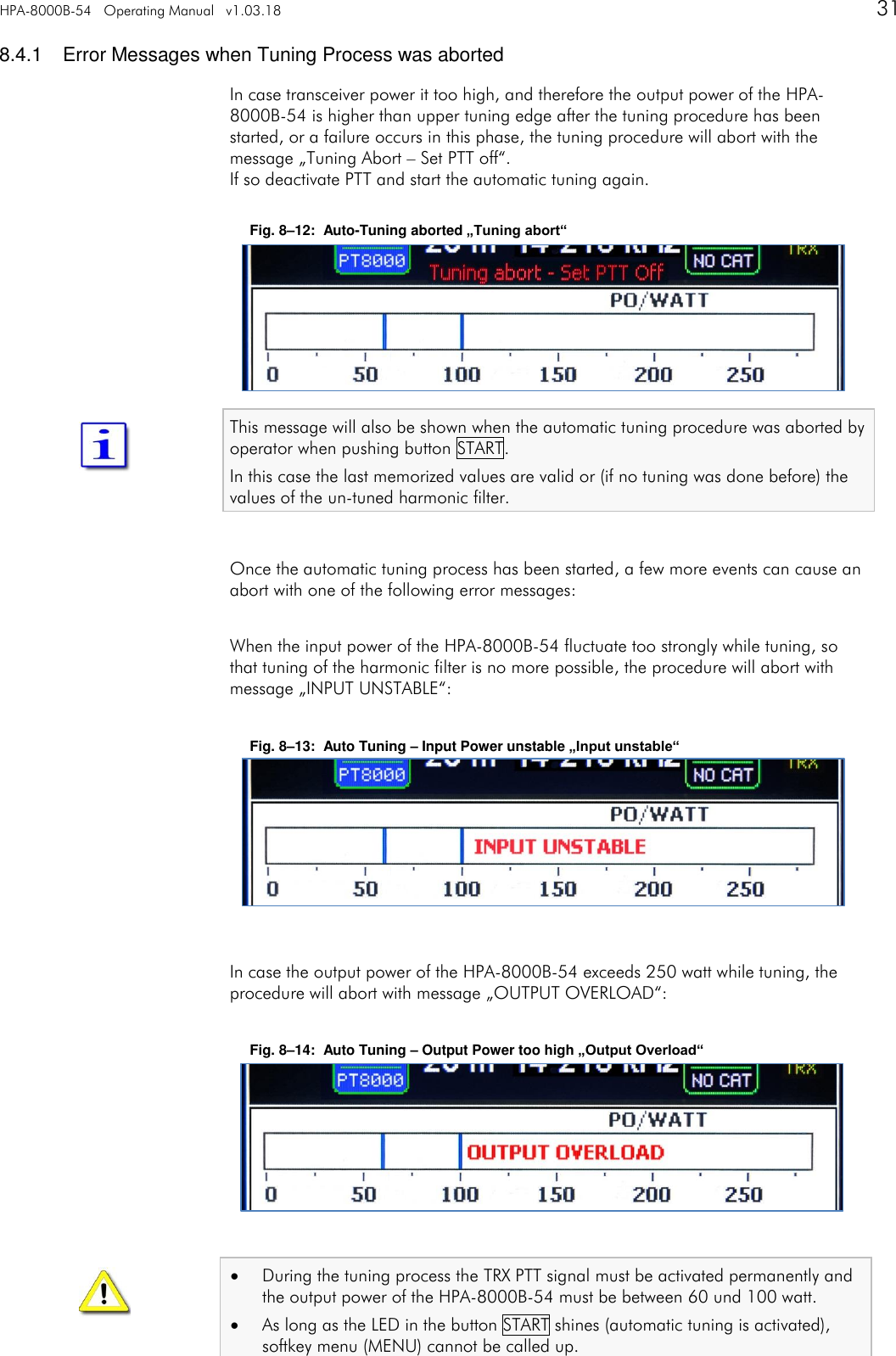
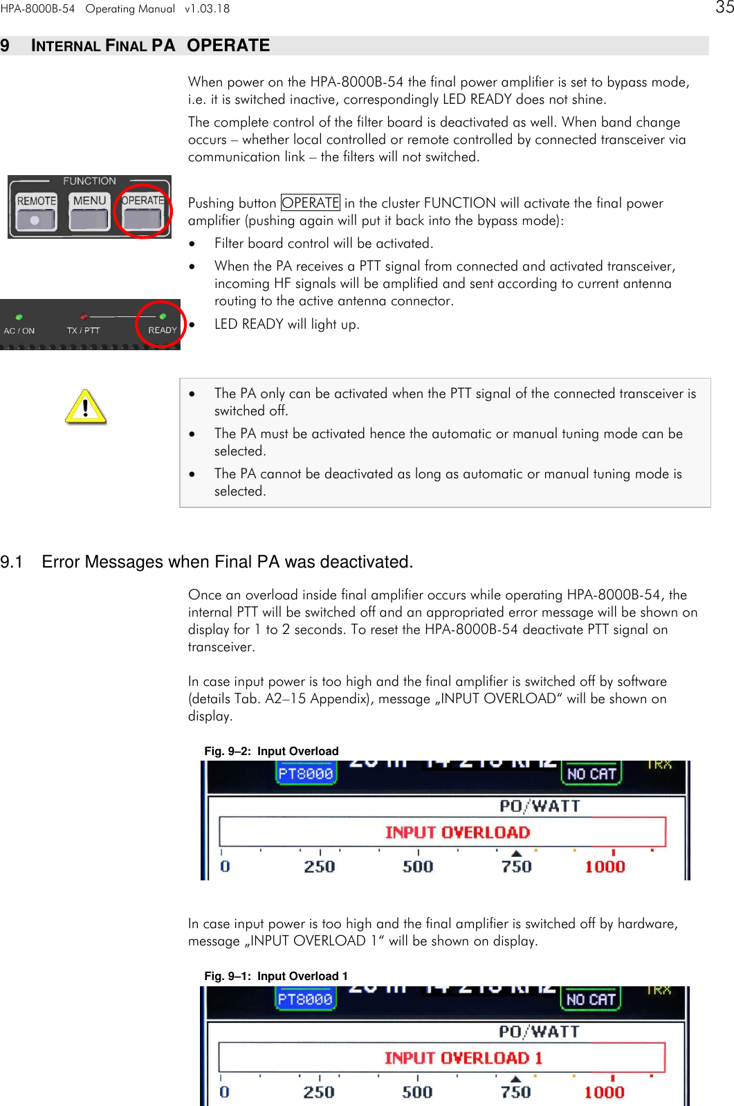
![HPA-8000B-54 Appendix A2 v1.03.18 43 Tab. A1–8: Subbands 20m Frequency [kHz] TUNE MEM [1] [2] [3] [4] [5] [6] [7] [8] [9] Lower 13950 13970 13990 14010 14030 14050 14070 14090 14110 Middle 13960 13980 14000 14020 14040 14060 14080 14100 14120 Upper 13970 13990 14010 14030 14050 14070 14090 14110 14130 TUNE MEM [10] [11] [12] [13] [14] [15] [16] [17] [18] [19] Lower 14130 14150 14170 14190 14210 14230 14250 14270 14290 14310 Middle 14140 14160 14180 14200 14220 14240 14260 14280 14300 14320 Upper 14150 14170 14190 14210 14230 14250 14270 14290 14310 14330 TUNE MEM [20] [21] [22] [23] [24] [25] Lower 14330 14350 14370 14390 14410 14430 Middle 14340 14360 14380 14400 14420 14440 Upper 14350 14370 14390 14410 14430 14450 Number of Subbands:25 Increment: 20 kHz Tab. A1–9: Subbands 17m Frequency [kHz] TUNE MEM [1] [2] [3] [4] [5] [6] [7] Lower 18050 18070 18090 18110 18130 18150 18170 Middle 18060 18080 18100 18120 18140 18160 18180 Upper 18070 18090 18110 18130 18150 18170 18190 Number of Subbands: 7 Increment: 20 kHz](https://usermanual.wiki/Hilberling-RF-Laboratories/HPA8000B-54/User-Guide-3368311-Page-43.png)
![44 Tab. A1–10: Subbands 15m Frequency [kHz] TUNE MEM [1] [2] [3] [4] [5] [6] [7] [8] [9] Lower 20950 20970 20990 21010 21030 21050 21070 21090 21110 Middle 20960 20980 21000 21020 21040 21060 21080 21100 21120 Upper 20970 20990 21010 21030 21050 21070 21090 21110 21130 TUNE MEM [10] [11] [12] [13] [14] [15] [16] [17] [18] [19] Lower 21130 21150 21170 21190 21210 21230 21250 21270 21290 21310 Middle 21140 21160 21180 21200 21220 21240 21260 21280 21300 21320 Upper 21150 21170 21190 21210 21230 21250 21270 21290 21310 21330 TUNE MEM [20] [21] [22] [23] [24] [25] [26] [27] [28] [29] Lower 21330 21350 21370 21390 21410 21430 21450 21470 21490 21510 Middle 21340 21360 21380 21400 21420 21440 21460 21480 21500 21520 Upper 21350 21370 21390 21410 21430 21450 21470 21490 21510 21530 TUNE MEM [30] Lower 21530 Middle 21540 Upper 21550 Number of Subbands:30 Increment: 20 kHz Tab. A1–11: Subbands 12m Frequency [kHz] TUNE MEM [1] [2] [3] [4] [5] [6] [7] [8] [9] Lower 24855 24875 24895 24915 24935 24955 24975 24995 25015 Middle 24865 24885 24905 24925 24945 24965 24985 25005 25025 Upper 24875 24895 24915 24935 24955 24975 24995 25015 25035 TUNE MEM [10] [11] Lower 25035 25055 Middle 25045 25065 Upper 25055 25075 Number of Subbands:11 Increment: 20 kHz](https://usermanual.wiki/Hilberling-RF-Laboratories/HPA8000B-54/User-Guide-3368311-Page-44.png)
![HPA-8000B-54 Appendix A2 v1.03.18 45 Tab. A1–12: Subbands 10m Frequency [kHz] TUNE MEM [1] [2] [3] [4] [5] [6] [7] [8] [9] Lower 28000 28040 28080 28120 28160 28200 28240 28280 28320 Middle 28020 28060 28100 28140 28180 28220 28260 28300 28340 Upper 28040 28080 28120 28160 28200 28240 28280 28320 28360 TUNE MEM [10] [11] [12] [13] [14] [15] [16] [17] [18] [19] Lower 28360 28400 28440 28480 28520 28560 28600 28640 28680 28720 Middle 28380 28420 28460 28500 28540 28580 28620 28660 28700 28740 Upper 28400 28440 28480 28520 28560 28600 28640 28680 28720 28760 TUNE MEM [20] [21] [22] [23] [24] [25] [26] [27] [28] [29] Lower 28760 28800 28840 28880 28920 28960 29000 29040 29080 29120 Middle 28780 28820 28860 28900 28940 28980 29020 29060 29100 29140 Upper 28800 28840 28880 28920 28960 29000 29040 29080 29120 29160 TUNE MEM [30] [31] [32] [33] [34] [35] [36] [37] [38] [39] Lower 29160 29200 29240 29280 29320 29360 29400 29440 29480 29520 Middle 29180 29220 29260 29300 29340 29380 29420 29460 29500 29540 Upper 29200 29240 29280 29320 29360 29400 29440 29480 29520 29560 TUNE MEM [40] [41] [42] [43] [44] [45] Lower 29560 29600 29640 29680 29720 29760 Middle 29580 29620 29660 29700 29740 29780 Upper 29600 29640 29680 29720 29760 29800 Number of Subbands:45 Increment: 40 kHz A1.4 Switchable L and C Elements Antenna Tuning Tab. A1–13: Switchable Inductances und Capacitances Harmonic Filter ID [1] [2] [3] [4] [5] [6] [7] [8] LOUT [nH] 25 50 100 200 400 800 1600 3200 COUT [pF] 5 10 22 47 82 180 560 1200 CC [pF] 10 20 40 94 164 300 940 2000 A1.5 Switch-off Criteria for INPUT OVERLOAD Tab. A1–14: Switch-off Criteria for Input Overload Error Message typ. Input Power Band PIN,max Input Overload 50 W all TBD](https://usermanual.wiki/Hilberling-RF-Laboratories/HPA8000B-54/User-Guide-3368311-Page-45.png)