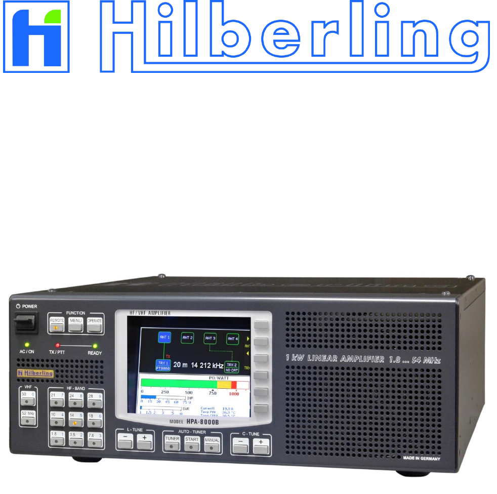
Hilberling RF Laboratories HPA8000B-54 Amateur Radio Power Amplifier 1 kW / 1.8 - 54 MHz User Manual HF VHF Transceiver
Hilberling GmbH RF Laboratories Amateur Radio Power Amplifier 1 kW / 1.8 - 54 MHz HF VHF Transceiver
User Manual
1 kW Power Amplifier
HPA-8000B-54
Operating Manual
Version 1.03.18
Copyright-notice to the ring binder title
All picture rights reserved by: Bundeswehr / PIZ Marine, DGzRS and Hilberling GmbH

HPA-8000B-54 Operating Manual v1.03.18 3
1 kW Power Amplifier
Hilberling HPA-8000B-54
Operating Manual
HPA-8000B-54
developed and manufactured in the EU
by
Hilberling GmbH
Heinrich-Hertz-Strasse 2
24790 Schacht-Audorf
Germany
Logo and name of Hilberling GmbH are registered trademarks
Distribution of the complete document is desired
However, each partial copy or distribution is prohibited
Errors and changes excepted

4
TABLE OF CONTENT
List of Figures ............................................................................................................................................. 6
List of Tables .............................................................................................................................................. 7
Federal Communications Commission (FCC) Statement .......................................................................... 8
1 About this Manual ...................................................................................................................................... 8
2 Important Notes ........................................................................................................................................ 9
2.1 General Precautions .......................................................................................................................... 9
2.2 Notes on Placing.............................................................................................................................. 10
3 Scope of Delivery ..................................................................................................................................... 11
3.1 Data Cables .................................................................................................................................... 11
3.2 Operating Manual and Software/Documentation CD-ROM .................................................................... 11
4 Connectors on Rear Panel ........................................................................................................................ 12
4.1 Connectors and Controls .................................................................................................................. 12
4.2 Pin Assignment J1 to J4 (D-Sub) ....................................................................................................... 13
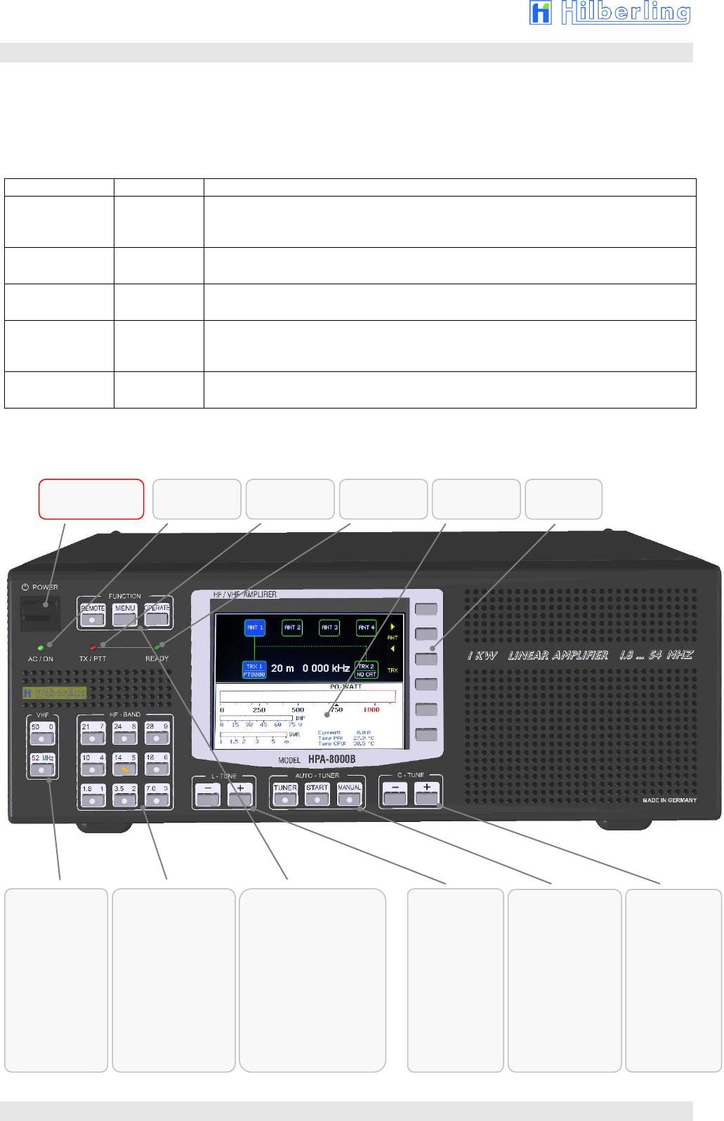
5 Operating and Display Elements ............................................................................................................. 14
5.1 Overview ........................................................................................................................................ 14
5.2 TFT Display ..................................................................................................................................... 15
5.3 Softkeys on Default Screen ............................................................................................................... 15
5.4 Softkey Menu .................................................................................................................................. 16
5.4.1 Display of Device Status SYSTEM INFORMATION ............................................................................. 17
5.4.1.1 Update Operating Software .............................................................................................................. 18
5.4.2 Device Configuration TRX SETUP .................................................................................................... 19
5.4.3 Brightness of Display DIM .............................................................................................................. 20
6 Installation / Initial Operation ................................................................................................................ 21
6.1 Cable Connections ........................................................................................................................... 21
6.2 Power-on ........................................................................................................................................ 21
7 Transceiver Set up ................................................................................................................................... 22
7.1 Select Transceiver Connector ............................................................................................................ 22
7.2 Allocate Transceiver Model ............................................................................................................... 22
7.3 Input Power .................................................................................................................................... 24
8 Antenna Setup .......................................................................................................................................... 25
8.1 Antenna Allocation to Bands ............................................................................................................. 25
8.2 Antenna and Antenna Tuner – basic Considerations ............................................................................ 27
8.3 Antenna Tuner ................................................................................................................................ 27
8.4 Automatic Antenna Tuning ............................................................................................................... 29
8.4.1 Error Messages when Tuning Process was aborted ............................................................................. 31
8.5 Manual Antenna Tuning ................................................................................................................... 32
8.5.1 Manual L Tuning .............................................................................................................................. 34
8.5.2 Manual C Tuning ............................................................................................................................. 34
8.5.3 Manual CC Tuning ........................................................................................................................... 34
9 Internal Final PA OPERATE .................................................................................................................... 35
9.1 Error Messages when Final PA was deactivated. ................................................................................. 35
9.2 ALC Connection ............................................................................................................................... 36
Appendix
A1 Technical Documents ............................................................................................................................... 38
A1.1 Technical Data ................................................................................................................................ 38
A1.2 Amateur Radio Bands ...................................................................................................................... 39
A1.3 Subbands Antenna Tuning ................................................................................................................ 40
A1.4 Switchable L and C Elements Antenna Tuning .................................................................................... 45
A1.5 Switch-off Criteria for INPUT OVERLOAD ........................................................................................... 45

HPA-8000B-54 Operating Manual v1.03.18 5
A1.6 Connecting Options ......................................................................................................................... 46
A2 Customer Information ............................................................................................................................. 47
A2.1 User Information ............................................................................................................................. 47
A2.1.1 Declaration of Conformity (shortened version) ................................................................................... 47
A2.1.2 Note Amateur Radio Operation ......................................................................................................... 47
A2.2 Warranty Terms .............................................................................................................................. 47
A2.3 Disposal Rules ................................................................................................................................. 48

6
LIST OF FIGURES
Fig. 2–1: Unfolding bails (front equipment feet) ...................................................................................... 10
Fig. 3–1: Cable D-Sub 9-pin .................................................................................................................. 11
Fig. 3–2: Cable D-Sub 25-pin ................................................................................................................ 11
Fig. 3–3: Manual HPA-8000B-54 ............................................................................................................ 11
Fig. 3–4: CD-ROM ................................................................................................................................ 11
Fig. 4–1: Connectors and Controls on Rear Panel .................................................................................... 12
Fig. 5–1: Operating and Display Elements .............................................................................................. 14
Fig. 5–2: TFT Display showing Default Screen ........................................................................................ 15
Fig. 5–3: Softkey Menu ........................................................................................................................ 16
Fig. 5–4: Softkey Menu MENU ............................................................................................................... 16
Fig. 5–5: Softkey Menu SYSTEM INFORMATION ..................................................................................... 17
Fig. 5–6: Screen SYSTEM INFORMATION ............................................................................................... 17
Fig. 5–7: Softkey Menu SOFTWARE UPDATE .......................................................................................... 18
Fig. 5–8: Screen SOFTWARE UPDATE .................................................................................................... 18
Fig. 5–9: Softkey Menu TRX SETUP ....................................................................................................... 19
Fig. 5–10: Screen TRX SETUP ............................................................................................................... 19
Fig. 5–11: Softkey Menu DIM ................................................................................................................ 20
Fig. 7–1: Transceiver Connector TRX 1 active / inactive........................................................................... 22
Fig. 7–2: Transceiver Connector TRX 1 active / inactive, PT-8000A allocated ............................................. 22
Fig. 7–3: Setup Transceiver Connector TRX1 .......................................................................................... 23
Fig. 7–4: Setup Transceiver Connector TRX2 .......................................................................................... 23
Fig. 7–8: Input Power Meter ................................................................................................................. 24
Fig. 8–1: Antenna Allocation – Toggle the active Transceiver ................................................................... 25
Fig. 8–2: Antenna Allocation – Change of Antenna Connector .................................................................. 26
Fig. 8–3: Antenna Allocation – Factory Setting ........................................................................................ 26
Fig. 8–4: Antenna Allocation – Variation Example.................................................................................... 26
Fig. 8–5: Antenna Tuner activated – Showing Frequency Information ....................................................... 28
Fig. 8–6: Antenna Tuner activated – no Frequency Information ............................................................... 28
Fig. 8–7: Auto-Tuning activated „Set PTT On“ ........................................................................................ 29
Fig. 8–8: Auto Tuning – Input Power too low „Tuning Signal low“ ............................................................ 30
Fig. 8–9: Auto Tuning – Input Power too high „Tuning Signal high“ .......................................................... 30
Fig. 8–10: Auto Tuning – Input Power ok „Tuning“ ................................................................................. 30
Fig. 8–11: Auto Tuning finished „Tuning done“ ....................................................................................... 30
Fig. 8–12: Auto-Tuning aborted „Tuning abort“ ...................................................................................... 31
Fig. 8–13: Auto Tuning – Input Power unstable „Input unstable“ ............................................................. 31
Fig. 8–14: Auto Tuning – Output Power too high „Output Overload“ ......................................................... 31
Fig. 8–15: Manual Tuning activated „Set PTT On“ ................................................................................... 32
Fig. 8–16: Manual Tuning – Input Power too low „Tuning Signal low“ ....................................................... 33
Fig. 8–17: Manual Tuning – Input Power too high „Tuning Signal high“ .................................................... 33
Fig. 8–18: Manual Tuning – Input Power ok „Please Tune“ ...................................................................... 33
Fig. 8–19: Manual Tuning – Center Capacitance CC ................................................................................ 34
Fig. 9–2: Input Overload ...................................................................................................................... 35
Fig. 9–1: Input Overload 1 .................................................................................................................... 35
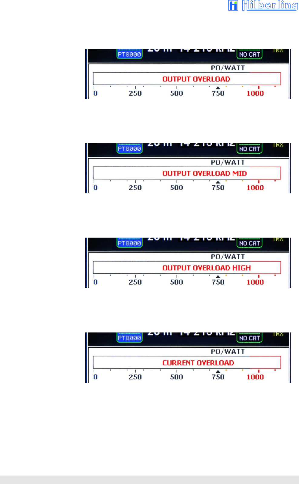
Fig. 9–3: Output Overload .................................................................................................................... 36
Fig. 9–4: Ouput Overload Mid ............................................................................................................... 36
Fig. 9–5: Ouput Overload High .............................................................................................................. 36
Fig. 9–6: Current Overload ................................................................................................................... 36

HPA-8000B-54 Operating Manual v1.03.18 7
LIST OF TABLES
Tab. 3–1: Scope of Delivery .................................................................................................................. 11
Tab. 4–1: Connectors on Rear Panel...................................................................................................... 12
Tab. 4–1: Connectors on Rear Panel (continued) .................................................................................... 13
Tab. 4–2: Pin Assignment D-Sub ........................................................................................................... 13
Tab. 5–1: Operating and Display Elements ............................................................................................. 14
Tab. A1-1: Technical Data .................................................................................................................... 38
Tab. A1–2: Frequency Bands HF ........................................................................................................... 39
Tab. A1–3: Frequency Band VHF ........................................................................................................... 39
Tab. A1–4: Subbands 160m .................................................................................................................. 40
Tab. A1–5: Subbands 80m ................................................................................................................... 41
Tab. A1–6: Subbands 40m ................................................................................................................... 42
Tab. A1–7: Subbands 30m ................................................................................................................... 42
Tab. A1–8: Subbands 20m ................................................................................................................... 43
Tab. A1–9: Subbands 17m ................................................................................................................... 43
Tab. A1–10: Subbands 15m .................................................................................................................. 44
Tab. A1–11: Subbands 12m .................................................................................................................. 44
Tab. A1–12: Subbands 10m .................................................................................................................. 45
Tab. A1–13: Switchable Inductances und Capacitances Harmonic Filter .................................................... 45
Tab. A1–14: Switch-off Criteria for Input Overload .................................................................................. 45
Tab. A1–15: Connecting Options TRX Setup ........................................................................................... 46

8
FEDERAL COMMUNICATIONS COMMISSION (FCC) STATEMENT
Note: This equipment has been tested and found to comply with the limits for a Class B digital device, pursuant to
part 15 of the FCC Rules. These limits are designed to provide reasonable protection against harmful interference in
a residential installation. This equipment generates, uses and can radiate radio frequency energy and, if not installed
and used in accordance with the instructions, may cause harmful interference to radio communications. However,
there is no guarantee that interference will not occur in a particular installation. If this equipment does cause harmful
interference to radio or television reception, which can be determined by turning the equipment off and on, the user is
encouraged to try to correct the interference by one or more of the following measures:
—Reorient or relocate the receiving antenna.
—Increase the separation between the equipment and receiver.
—Connect the equipment into an outlet on a circuit different from that to which the receiver is connected.
—Consult the dealer or an experienced radio/TV technician for help.
FCC ID: V84HPA8000B-54
This device complies with Part 15 of the FCC rules. Operation is subject to the following two
conditions:
(1) this device may not cause harmful interference, and
(2) this device must accept any interference received, including interference that may cause
undesired operation.
1 ABOUT THIS MANUAL
In this manual the following signs and symbols are used:
The STOP sign indicates a warning that must be obeyed for safety reasons.
This sign indicates an important explanation or a specific advice which should be obeyed.
An additional information or explanation is indicated this way.
Copyright © 2017 by Hilberling GmbH

HPA-8000B-54 Operating Manual v1.03.18 9
2 IMPORTANT NOTES
Read and save this Operating Manual carefully before attempting to operate the device. This manual contains
important safety and operating instructions to prevent damages caused by faulty operation.
2.1 General Precautions
WARNING HIGH VOLTAGE !
Do not touch antenna, antenna cable or antenna plugs and sockets during transmission. This may result in
an electrical shock or burn of your skin by high-frequency.
WARNING !
The plug of the 230V power cord represents the designated separation device of the amplifier from the
mains according to standard. The socket must be placed near the amplifier and easily accessible. The
power cord must be able easily disconnected from mains.
CAUTION !
Make sure that no objects may penetrate into device or will touch connectors on rear panel of the power
amplifier. This could cause electrical shock and severe injury.
PROTECT the amplifier from precipitation like rain or any liquid. Do not operate the power amplifier in
excessively dusty or very humid environment.
PROTECT the amplifier from operation by any unauthorized person notably children.
AVOID placing and using the power amplifier in areas with temperatures below -15°C or above +50°C.
If the environment temperature drops so low that the dew point is undercut, avoid operating before the
devices are dried completely.
AVOID placing the power amplifier against a wall. This may inhibit proper air circulation and could cause
overheat. Do not cover any air inlets and outlets at front, bottom and rear panel of the device.
10
2.2 Notes on Placing
When selecting the place for operating the HPA-8000B-54 bear in mind the general limitation
concerning environmental conditions as outlined in the specifications and the cautions at the very
beginning of this manual (see section 2.1).
Always handle the HPA-8000B-54 with care – consider the weight of ca. 20 kg (ca. 50 lbs).
Please make sure proper air circulation. Do not cover any air inlets and outlets at front, bottom and
rear panel of the device.
Choose the place of installation so that all connectors of the HPA-8000B-54 are reachable at any
time, this is especially true for the supply cable connector.
Select a power outlet that is capable to handle the power requirements. Connect your HPA-8000B-
54 to a proper ground system. In addition, observe the relevant technical electrical regulations and
the local regulations of the power supplier. A good grounding system not only prevents electrical
shock but also helps to ensure trouble free operation and will diminish television and broadcast
interference (TVI/BCI).
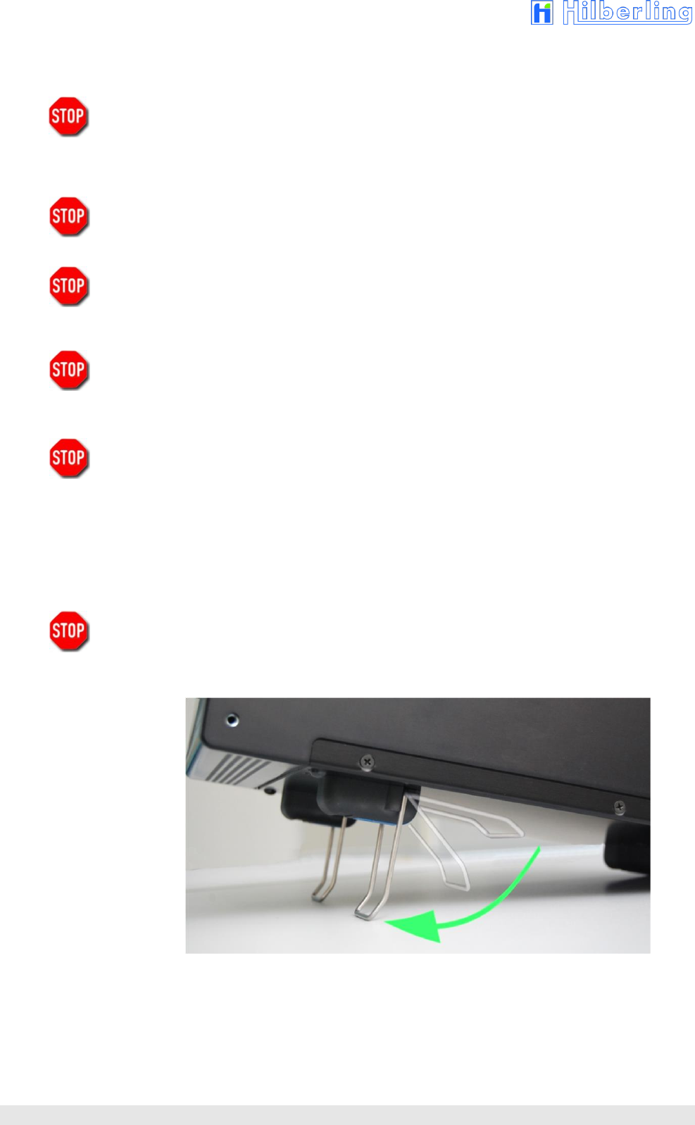
For your convenience you might raise the front of HPA-8000B-54 by unfolding and locking tilt bails mounted at the
front equipment feet into front position as shown on Fig. 2–1.
If a large resistance will complicate the unfolding, please easily spread the bail for hurdle the locking
nib to avoid damage of the equipment foot.
Fig. 2–1: Unfolding bails (front equipment feet)
HPA-8000B-54 Operating Manual v1.03.18 11
3 SCOPE OF DELIVERY
Examine your HPA-8000B-54 for signs of damage during shipping. Should any damage be apparent please take
appropriate measures (contacting your carrier). We recommend to retain all packing material – it might be used for
shipment of the power amplifier in the future. It is specially made for the HPA-8000B-54.
Listed below the hardware and all accessories delivered with your HPA-8000B-54. Make sure you have received and
unpacked everything:
Tab. 3–1: Scope of Delivery
Quantity
Description
Fig.
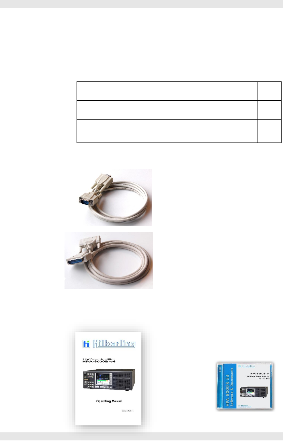
1
D-Sub 9-pin (HPA-8000B-54 ⬄ PT-8000A)
3–1
1
D-Sub 25-pin (HPA-8000B-54 ⬄ PT-8000A)
3–2
1
Operating Manual
3–3
1
Software CD-ROM
• HPA-8000B-54 Update Software (Windows®)
• Operating Manual (PDF)
3–4
3.1 Data Cables
Fig. 3–1: Cable D-Sub 9-pin
Data Cable (HPA-8000B-54 ⬄ PT-8000A)
Length approx. 2.0 m
Fig. 3–2: Cable D-Sub 25-pin
Data Cable (HPA-8000B-54 ⬄ PT-8000A)
Length approx. 1.8 m
3.2 Operating Manual and Software/Documentation CD-ROM
Fig. 3–3: Manual HPA-8000B-54
Fig. 3–4: CD-ROM
12
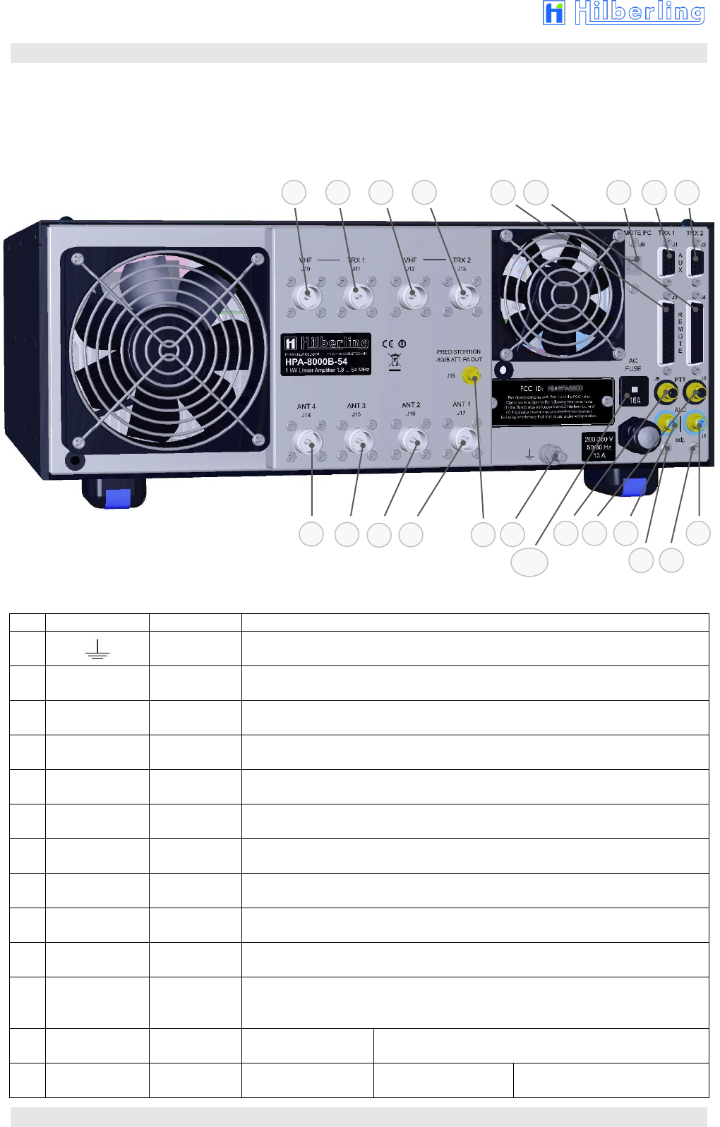
4 CONNECTORS ON REAR PANEL
This section introduces the connectors on the rear panel of the HPA-8000B-54.
4.1 Connectors and Controls
Fig. 4–1: Connectors and Controls on Rear Panel
Tab. 4–1: Connectors on Rear Panel
No
Label
Type
Description
E
Threaded Bolt
M6
Grounding connector for station ground
FUSE
AC FUSE
Thermal Fuse
16 A time-lag
Thermal circuit breaker, 230 V AC, resettable
J1
AUX
TRX 1
DE-9
(D-Sub 9-pin)
Output / input signals for transceiver 1 (Wiring Tab. 4–2)
J2
AUX
TRX 2
DE-9
(D-Sub 9-pin)
Output / input signals for transceiver 2 (Wiring Tab. 4–2)
J3
REMOTE
TRX 1
DB-25
(D-Sub 25-pin)
Output / input signals for transceiver 1 (Wiring Tab. 4–2)
J4
REMOTE
TRX 2
DB-25
(D-Sub 25-pin)
Output / input signals for transceiver 2 (Wiring Tab. 4–2)
J5
PTT
TRX 1
RCA
HF PTT transceiver 1 +5 V / GND (GND = TX)
J6
PTT
TRX 2
RCA
HF PTT transceiver 2 +5 V / GND (GND = TX)
J7
ALC
TRX 1
RCA
ALC output transceiver 1; adjustable by PJ7
J8
ALC
TRX 2
RCA
ALC output transceiver 2 ; adjustable by PJ8
J9
REMOTE PC
USB-B
Input / output data (USB Cable Fig. 3–1)
1. Interface to PC for HPA-8000B-54 remote operation (CAT)
2. Interface to PC for update the software on HPA-8000B-54
J10
VHF
TRX 1
N
VHF input transceiver 1
only for TRX PT-8000A
50 MHz TRX PT-8000A only
‘CAT Type’ selection: ‘Hilberling’ (Sec. 5.4.2 and 7.2) *
J11
TRX 1
N
Input transceiver 1
1.8 … 29.7 MHz
TRX PT-8000A
1.8 … 29.7 / 50 MHz
TRX by other manufacturer
J5
J8
J6
J7
J14
J15
J18
J16
J17
E
J1
J2
J3
J4
J10
J11
J9
J12
J13
FUSE
PJ8
PJ7
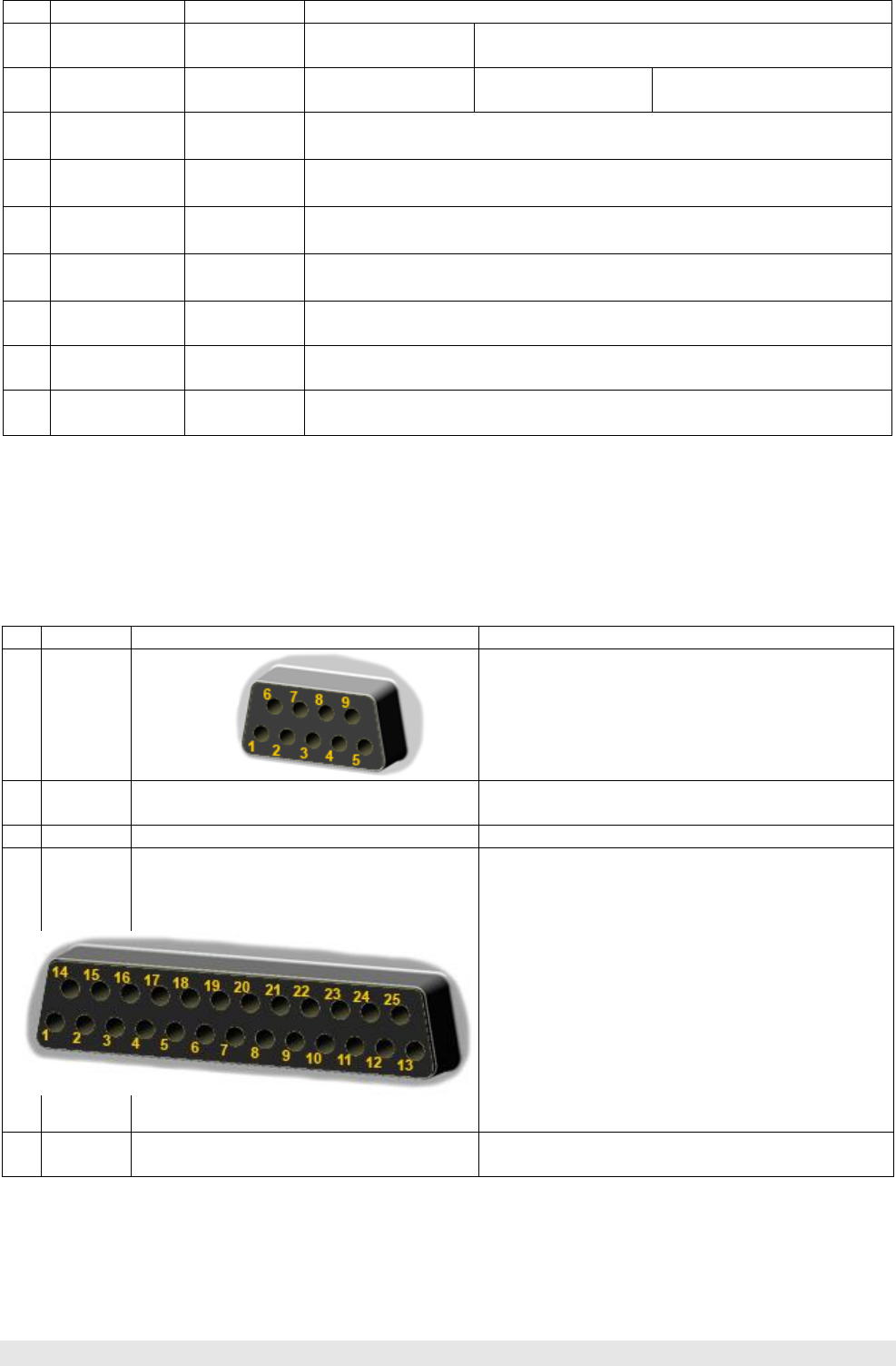
HPA-8000B-54 Operating Manual v1.03.18 13
Tab. 4–1: Connectors on Rear Panel (continued)
No.
Label
Type
Description
J12
VHF
TRX 2
N
VHF input transceiver 2
only for TRX PT-8000A
50 MHz TRX PT-8000A only
‘CAT Type’ selection: ‘Hilberling’ (Sec. 5.4.2 and 7.2). *
J13
TRX 2
N
Input transceiver 2
1.8 … 29.7 MHz
TRX PT-8000A
1.8 … 29.7 / 50 MHz
TRX by other manufacturer
J14
ANT. 4
N
HF output antenna 4
J15
ANT. 3
N
HF output antenna 3
J16
ANT. 2
N
HF output antenna 2
J17
ANT. 1
N
HF output antenna 1
J18
PREDISTORSION
-60dBc ATT. PA OUT
SMA
HF Output, attenuated by 60 dB , e.g. for predistorsion on TRX
PJ7
ALC adj.
TRX 1
Trim Pot
Adjustment of ALC output on transceiver 1 within range −10 … +10 V
at RCA J7 and D-Sub J1 Pin 6
PJ8
ALC adj.
TRX 2
Trim Pot
Adjustment of ALC output on transceiver 2 within range −10 … +10 V
at RCA J8 and D-Sub J2 Pin 6
* Inputs J10 and J12 are only usable for a connection to the Hilberling PT-8000A Transceiver.
If so select option ‘Hilberling’ as a ‘CAT Type’ at the TRX Setup (see Section 5.4.2 and 7.2).
4.2 Pin Assignment J1 to J4 (D-Sub)
Tab. 4–2: Pin Assignment D-Sub
No.
Label
Figure
Pin Assignment
J1
AUX
TRX 1
1 HF-PTT TRX 1 +5V (GND=TX) 6 ALC OUT
(−10 … +10V)
*
2 <not connected> 7 GND
3 < not connected > 8 < not connected >
4 VHF-PTT TRX 1 +5V (GND=TX) 9 TX INHIBIT (GND=TX)
5 GND
* adjustable by PJ7
J2
AUX
TRX 2
as J1
Assignment analogous to J1
Pin 6 ALC OUT adjustable by PJ8
J3
REMOTE
TRX 1
1 GND 14 < not connected >
2 < not connected > 15 Bit A of Band Data
3 Bit B of Band Data 16 Bit C of Band Data
4 Bit D of Band Data 17 GND
5 < not connected > 18 < not connected >
6 < not connected > 19 GND
7 < not connected > 20 < not connected >
8 < not connected > 21 < not connected >
9 RX TTL for CAT 5V TTL or CI-V 22 TX TTL for CAT 5V TTL
10 Band Data Voltage Input 23 GND
11 GND 24 RS232 RX (CAT)
12 RS232 TX (CAT) 25 GND
13 GND
J4
REMOTE
TRX 2
as J3
Assignment analogous to J3
14
5 OPERATING AND DISPLAY ELEMENTS
Section 5.1 and 5.2 introduce operating and display elements at the front panel. Furthermore section 5.3 describes
the softkey menus and screens for configuration, system information and software update.
5.1 Overview
Tab. 5–1: Operating and Display Elements
Fig. 5–1: Operating and Display Elements
Element
Label
Description
ONOFF
Main Switch
POWER
When power on:
All LEDs – including LEDs assembled to buttons – will light up for approx. 1 second (function test),
LED AC / ON will light up permanently.
LED AC / ON
AC / ON
Lights up when device is powered on and supply voltage of 230 V AC is applied.
LED TX / PTT
TX / PTT
Lights up when the PA is activated (LED READY shine) and the HPA-8000B-54 receives a PTT signal.
LED READY
READY
Lights up when the PA of HPA-8000B-54 was activated by pushing button OPERATE.
When the PA is not activated, transceiver HF signals will be sent without amplification to the currently
switched antenna output connector.
TFT Display
÷
The TFT display shows the relevant operating parameters and at a time the current functions of the
so-called ‘softkeys’ placed right hand side of the display as well.
POWER
ONOFF
TFT Display
Sec. 5.2
Softkeys
Sec. 5.3
LED AC / ON
LED TX / PTT
VHF
Selection of the
6 m VHF
amateur radio
band
without
remote control
by TRX/PC
Sec. 8.1
HF - BAND
Selection of an
HF amateur
radio band
without
remote control
by TRX/PC
Sec. 8.1
FUNCTION
REMOTE
Remote control of HPA,
Sec. 10.3
MENU
Call-up of softkey menu
Sec. 5.3
OPERATE
Activation of
power amplifier (final PA)
Sec. 9
L - TUNE
– / +
manual tuning
of inductances
Sec. 8.5.1
AUTO TUNER
TUNER
Activation of the
tuner, Sec. 8.3
START
of automatic
tuning, Sec. 8.4
MANUAL
manual tuning
Sec. 8.5
C - TUNE
– / +
manual tuning
of
capacitances
Sec. 8.5.2
LED READY
HPA-8000B-54 Operating Manual v1.03.18 15
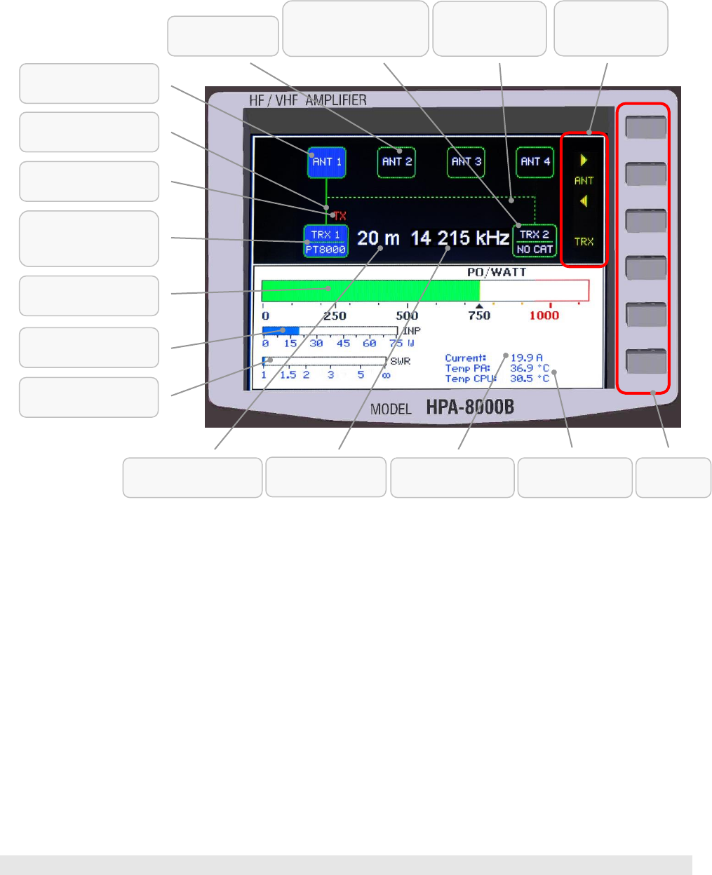
5.2 TFT Display
In default view („default screen“) the TFT display gives a status overview about relevant
operating parameters of the HPA-8000B-54. These include displaying the active
transceiver with current band and transmission frequency, as well as the antenna
which is allocated to the band, furthermore indication of power, SWR and
temperature, as well as the antenna transceiver configuration of the inactive
transceiver.
Fig. 5–2: TFT Display showing Default Screen
5.3 Softkeys on Default Screen
Right next to the display there are six buttons placed in vertical line as ‘Softkeys’
(buttons with changeable function) to operate the HPA-8000B-54. They allow to
activate or select functions shown on display as a so-called ‘Softkey Menu’ at right
border (see Sec. 5.4).
Exceptions to this rule – so softkeys without a menu – the following functions are
existing:
Toggle the antenna connector and the active transceiver is directly possible by
using the upper three softkeys on default screen (Sec. 8.1).
Manual tuning the center capacitances of the harmonic filter (CC-Tune) will be
done directly by using the two lower softkeys on default screen (Sec. 8.5.3).
Softkeys
Temperature
PA und CPU
Power Meter
Power Output POUT
SWR Meter
Power Meter
Power Input PIN
TRX Connector 1
(device allocated)
(active)
TX Indicator TRX 1
(HPA air TRX 1)
Antenna 2 / 3 / 4
(inactive)
Transmit Frequency
(active TRX)
Antenna Routing
TRX 2
(inactive)
Amateur Radio Band
(active TRX)
TRX Connector 2
(no device allocated)
(inactive)
Antenna and
TRX Toggle
(by softkeys)
Current Drain
PA
Antenna Routing
TRX 1 (active)
Antenna 1
(active)
16
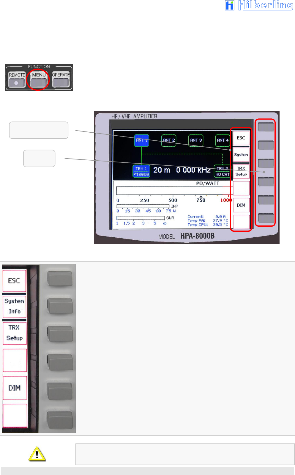
5.4 Softkey Menu
The six keys (so-called ‘softkeys’) right next to the display give access to the functions
shown on the display as a so-called ‘Softkey Menu’ at right border (exceptions see
Sec. 8.1 and 8.5.3).
When power on the HPA-8000B-54 the softkey menu is removed.
Pushing the button MENU in the cluster FUNCTION will show the softkey menu
MENU (pushing again will remove the menu):
Fig. 5–3: Softkey Menu
Fig. 5–4: Softkey Menu MENU
Remove the softkey menu.
Softkey menu and screen SYSTEM INFORMATION will be called up to show system
information and operating parameters (Sec. 5.4.1).
Softkey menu and screen TRX SETUP will be called up to show and edit device
configuration (Sec. 5.4.2).
Softkey menu DIM will be called up to adjust brightness of display
(Sec. 5.4.3).
If automatic or manual antenna tuning is activated (Sec. 8.4 u. 8.5) the softkey menu
(MENU) cannot be called up.
Softkeys
Softkey Menu MENU
HPA-8000B-54 Operating Manual v1.03.18 17
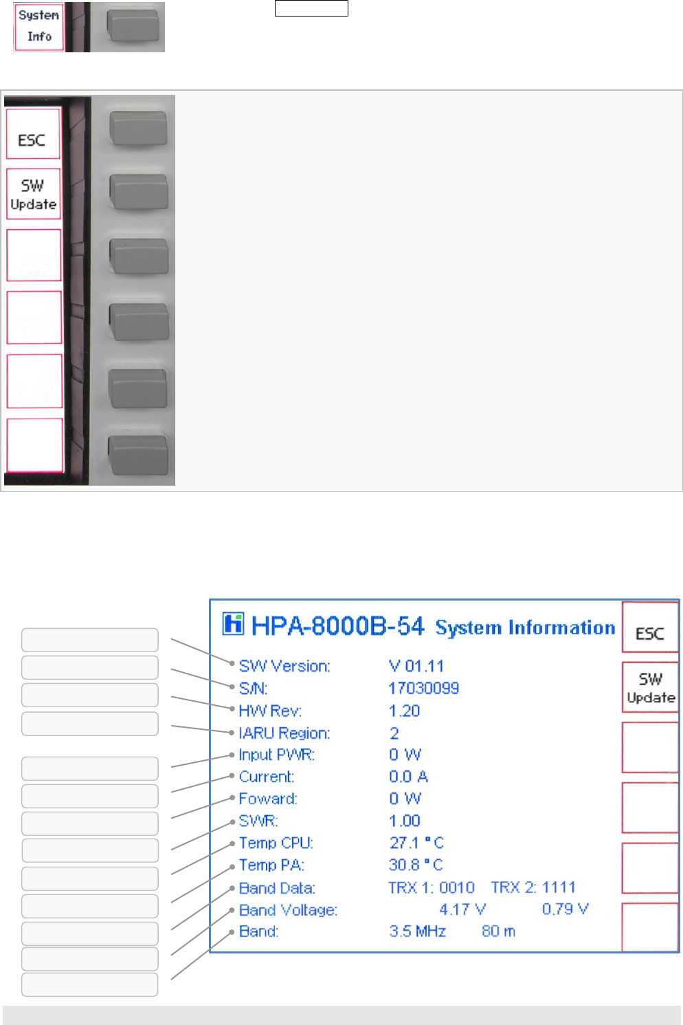
5.4.1 Display of Device Status SYSTEM INFORMATION
Pushing softkey SYSTEM Info from softkey menu MENU (Fig. 5–4) will call up softkey
menu and screen SYSTEM INFORMATION:
Fig. 5–5: Softkey Menu SYSTEM INFORMATION
Return to softkey menu MENU (Sec. 5.4) and default screen.
Softkey menu and screen SOFTWARE UPDATE will be called up to update the
operation software (Sec. 5.4.1.1).
System information will be shown on display:
Fig. 5–6: Screen SYSTEM INFORMATION
Temperature PA
Amateur Radio Band
Hardware Revision
Software Version
Serial Number
Input Power
Band Info digital
Current Drain PA
Forward Power
Temperature CPU
Band Info analog
Standing Wave Ratio
IARU Region
18
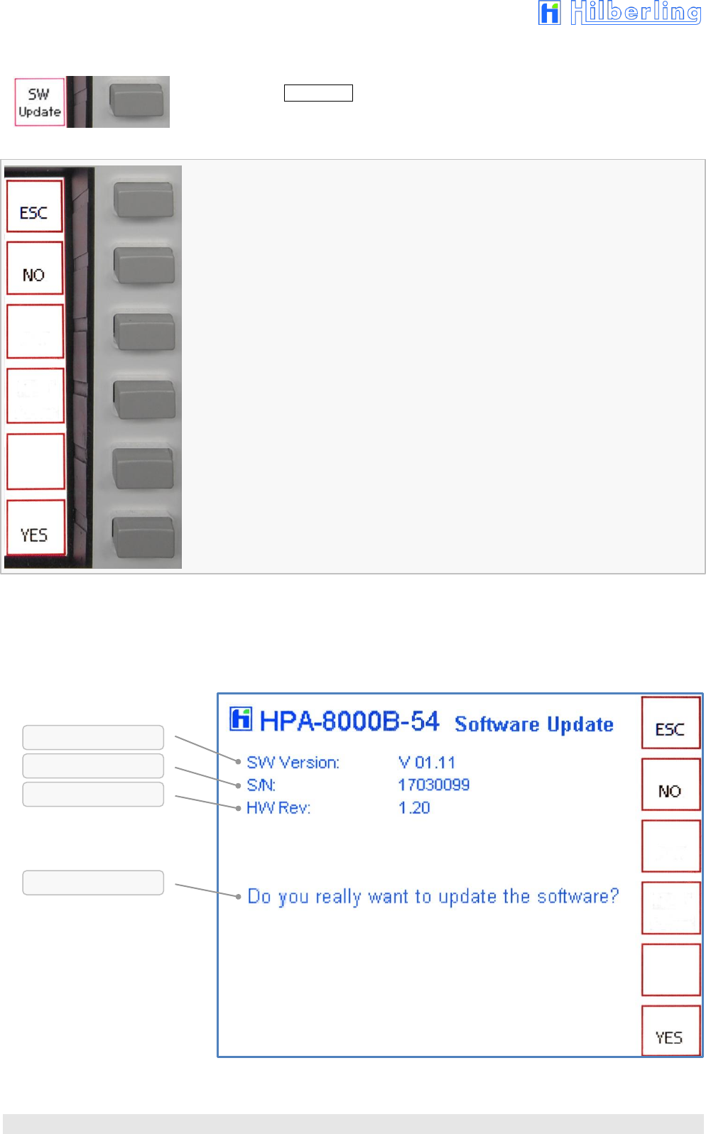
5.4.1.1 Update Operating Software
Pushing softkey SW Update from softkey menu SYSTEM (Fig. 5–5) will call up softkey
menu and screen SOFTWARE UPDATE:
Fig. 5–7: Softkey Menu SOFTWARE UPDATE
Return to softkey menu SYSTEM und screen SYSTEM INFORMATION (Sec. 5.4.1).
Software update will not be executed.
Return to softkey menu SYSTEM und screen SYSTEM INFORMATION (Sec. 5.4.1).
Software update will be continued.
A new screen will be shown on display (for details, see appendix A1–6).
All entries starting from row 4 will be removed and a security query will be shown
instead:
Fig. 5–8: Screen SOFTWARE UPDATE
Select ESC or NO to end the update procedure.
Select YES to continue the update procedure, see appendix Sec. A1–6.
Hardware Revision
Software Version
Serial Number
Security Query
HPA-8000B-54 Operating Manual v1.03.18 19
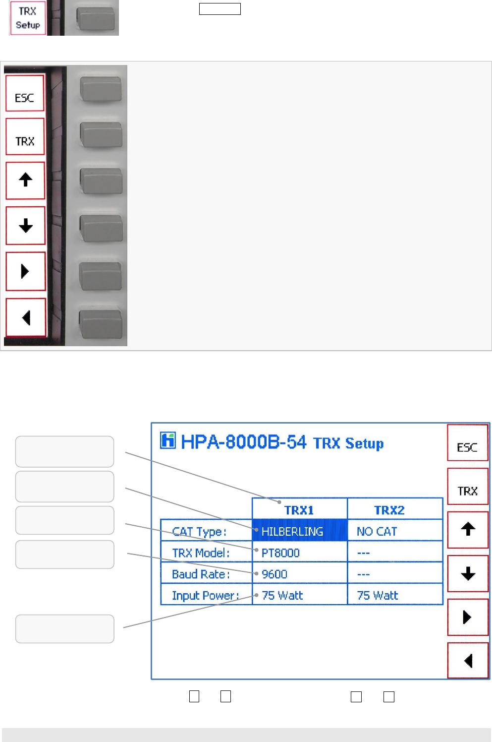
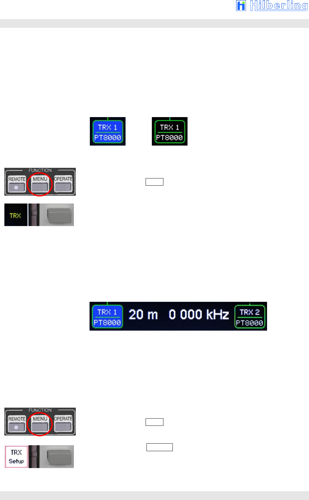
5.4.2 Device Configuration TRX SETUP
Pushing Softkey TRX Setup from softkey menu MENU (Fig. 5.4) will call up softkey
menu and screen TRX SETUP:
Fig. 5–9: Softkey Menu TRX SETUP
Return to softkey menu MENU (Sec. 5.4) and default screen.
Toggles transceiver connector (TRX1 ⬄ TRX2) whose settings shall be edited.
When the menu will be called up the currently active TRX connector is the selected one
(in row CAT Type the field of selected TRX will be shown inverse).
Cyclic change of editable fields bottom-up.
Non-editable fields (= no option available) will be skipped.
Cyclic change of editable fields top down.
Non-editable fields (= no option available) will be skipped.
Cyclic change of manufacturer (‘CAT Type’), TRX Model and Baud Rate – depending
on selected field and its available options – in listed order (see Table A2–16/A2–17
Appendix A2–6).
Cyclic change of ‘CAT Type’, TRX Model and Baud Rate– depending on selected field
and its available options – in reverse listed order (see Table A2–16/A2–17 Appendix
A2–6).
On screen a table will be shown to check out or edit interface parameters and input
power range for each of both transceiver connectors.
Fig. 5–10: Screen TRX SETUP
Push softkeys and for line break, push softkeys ␐ and ␑ to select respective
parameters (see Tab. A2–16/A2–17 Appendix Sec. A2.6).
selected
Transceiver Connector
Selection
Manufacturer / RS232
Selection
TRX Model / CAT Type
Input Power Range
(just for information)
Selection
Baud Rate
20
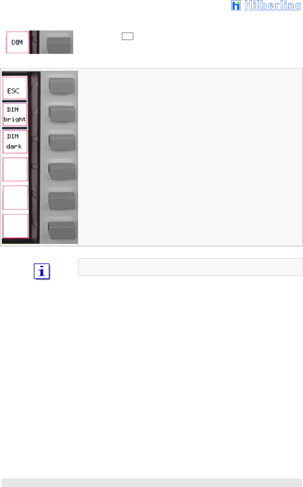
5.4.3 Brightness of Display DIM
Pushing softkey DIM from softkey menu MENU (Fig. 5.4) will call up the menu DIM to
vary the brightness of the display:
Fig. 5–11: Softkey Menu DIM
Return to softkey menu MENU (Sec. 5.4).
Lightens up the display stepwise.
Darkens the display stepwise.
Display brightness is adjustable in ten steps.

HPA-8000B-54 Operating Manual v1.03.18 21
6 INSTALLATION / INITIAL OPERATION
Prior to any operation please read this manual carefully.
The HPA-8000B-54 is unlocked by software according to the band plans of that IARU
region the device is delivered (Tab A2–2 and A2–3).
The IARU region can be changed by software update.
Prior applying main power to the HPA-8000B-54 and power-on please verify the
remarks in the following section 6.1.
6.1 Cable Connections
Please check at rear panel of HPA-8000B-54 (Fig. 4–1):
Grounding stud (E) is connected to station ground,
HF cables from HPA-8000B-54 (J11 TRX1 / J13 TRX 2) to transceiver(s)
(PT-8000A: J2 HF-ANT1 / J3 HF-ANT 2) are installed properly,
Only in case a PT-8000A is being connected:
VHF cable from HPA-8000B-54 (J10 VHF TRX 1 / J12 VHF TRX 2) to
PT-8000A (J1 VHF-ANT) is installed properly,
Antenna(s) (J14 ANT 4 … J17 ANT 1) is/are connected properly,
Data cable from HPA-8000B-54 (J1 AUX TRX 1 / J2 AUX TRX 2;
alternatively: J5 PTT TRX 1 / J6 PTT TRX 2 und J7 ALC TRX 1 /J8 ALC TRX 2)
to transceiver/s (PT-8000A: J17 AUX-TX) is/are installed,
Data cable from HPA-8000B-54 (J3 REMOTE TRX 1 / J4 REMOTE TRX 2)
to transceiver/s (PT-8000A: J21 TRANSVERTER) is/are installed.
6.2 Power-on
When all of the connections have been made and checked (6.1) put the
HPA-8000B-54 into operation as follows:
Ensure that the main switch (POWER) of the HPA-8000B-54 is switched off
(pushed down),
Connect the supply cable to main power socket,
(200 … 260 V AC / 50 … 60 Hz);
Switch on POWER at HPA-8000B-54 main switch.
All LEDs will light up for approximately one second (function test).
LED AC/ON will light up permanently.
On the display the default screen will be shown (Fig. 5–2).
22
7 TRANSCEIVER SET UP
As described in section 7 and 8, prior first operation of the HPA-8000B-54 basic
settings are needed to undertake.
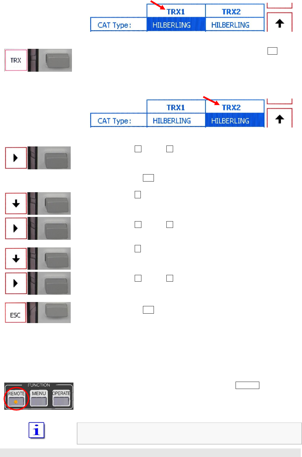
7.1 Select Transceiver Connector
When powered-on the first time, connector TRX 1 (J11/J10) is selected by default
(= “active”) and therefore shown with a blue background.
Fig. 7–1: Transceiver Connector TRX 1 active / inactive
If necessary the transceiver connector will be switched as follows:
1. If a softkey menu is shown on display:
Pushing button MENU in the cluster FUNCTION will remove the current
softkey menu.
2. Pushing softkey TRX (default screen) toggles connectors TRX 1 and TRX 2.
When active, the TRX indicator will be shown with a blue background
(Fig. 7–1).
7.2 Allocate Transceiver Model
As a factory setting TRX model PT-8000A is allocated to both TRX connectors TRX 1
and TRX 2 (the display will show ‘PT8000’).
Fig. 7–2: Transceiver Connector TRX 1 active / inactive, PT-8000A allocated
Due to the allocation the default parameters of CAT mode (Band Data, Band Voltage,
RS232) of the selected transceiver will be switched at HPA-8000B-54s D-Sub
connectors REMOTE J3 / J4.
The allocation is made by browsing manufacturer and model list provided by
operation software (see Tab. A2–16 Appendix).
A transceiver model will be allocated as follows:
1. If no softkey menu is shown on display:
Pushing button MENU in the cluster FUNCTION will show softkey menu
MENU (Fig. 5–4).
2. Pushing softkey TRX Setup will call up softkey menu and screen TRX Setup
(Fig. 5–9 and 5–10).
In case TRX 1 is currently the active TRX connector, the first field in column
TRX1 of the table (row CAT Type, see Fig. 7–3) is shown with a blue
background. Subsequent adjustments by arrow softkeys will have an effect to
this connector.
HPA-8000B-54 Operating Manual v1.03.18 23
Fig. 7–3: Setup Transceiver Connector TRX1
3. IF adjustments are to do for the other connector, pushing softkey TRX will
toggle the connectors.
Therefore the first field in the other column will be shown with a blue
background:
Fig. 7–4: Setup Transceiver Connector TRX2
4. Push softkey ␐ (possibly ␑ ) to select a manufacturer from CAT Type list.
In case the desired manufacturer is not listed examine the possibility of an
RS232 linkage to the connected transceiver (choose option RS232). If linkage
is not possible, choose option NO CAT. Exit screen and softkey menu by
pushing softkey ESC.
5. Push softkey to select the next row which provides choice.
If more than one option is selectable in row TRX Model it is the field in this
row (the field is shown with a blue background).
Push softkey ␐ (possibly ␑ ) to select an option from list (TRX Model or
transmission mode CI-V / Band Voltage / CAT 1-2 / Band Data).
6. Push softkey to select the next row which provides choice.
If there is more than one baud rate selectable it is the field in this row (the
field is shown with a blue background).
Push softkey ␐ (possibly ␑ ) to select a baud rate supported by the shown
TRX Model.
7. When all settings has been carried out exit screen and softkey menu by
pushing softkey ESC.
In case a manufacturer (or option NO CAT , see row CAT Type, Point 4.) is selected
and whether in row TRX Model nor in row Baud Rate an option is selectable, no more
options are available. The last row shows only as an information the maximum
allowed RF input power (75
W).
When the selected and connected transceiver is powered-on, both devices will set up
a communication link.
If the connection is completed successfully, the LED in button REMOTE will light up.
The HPA-8000B-54 will now take over the data for band selection and current
frequency from the connected transceiver.
When HPA-8000B-54 is set to REMOTE operation the band selection buttons are
locked.

24
7.3 Input Power
The range of input power of the HPA-8000B-54 is 0 … 75
Watt for both transceiver
connectors TRX 1 and TRX 2.
On default screen the power meter is showing the current input power PIN:
Fig. 7–8: Input Power Meter
HPA-8000B-54 Operating Manual v1.03.18 25
8 ANTENNA SETUP
Prior first operation it is also necessary to verify or change the allocation of amateur
radio bands to the used antenna connectors (see Sec. 8.1).
Before transmit operation starts with high power it is expedient to carry out tuning the
HPA-8000B-54 to the connected and allocated antennas in that frequency ranges the
radio operation is scheduled (see Sec. 8.4 and 8.5).
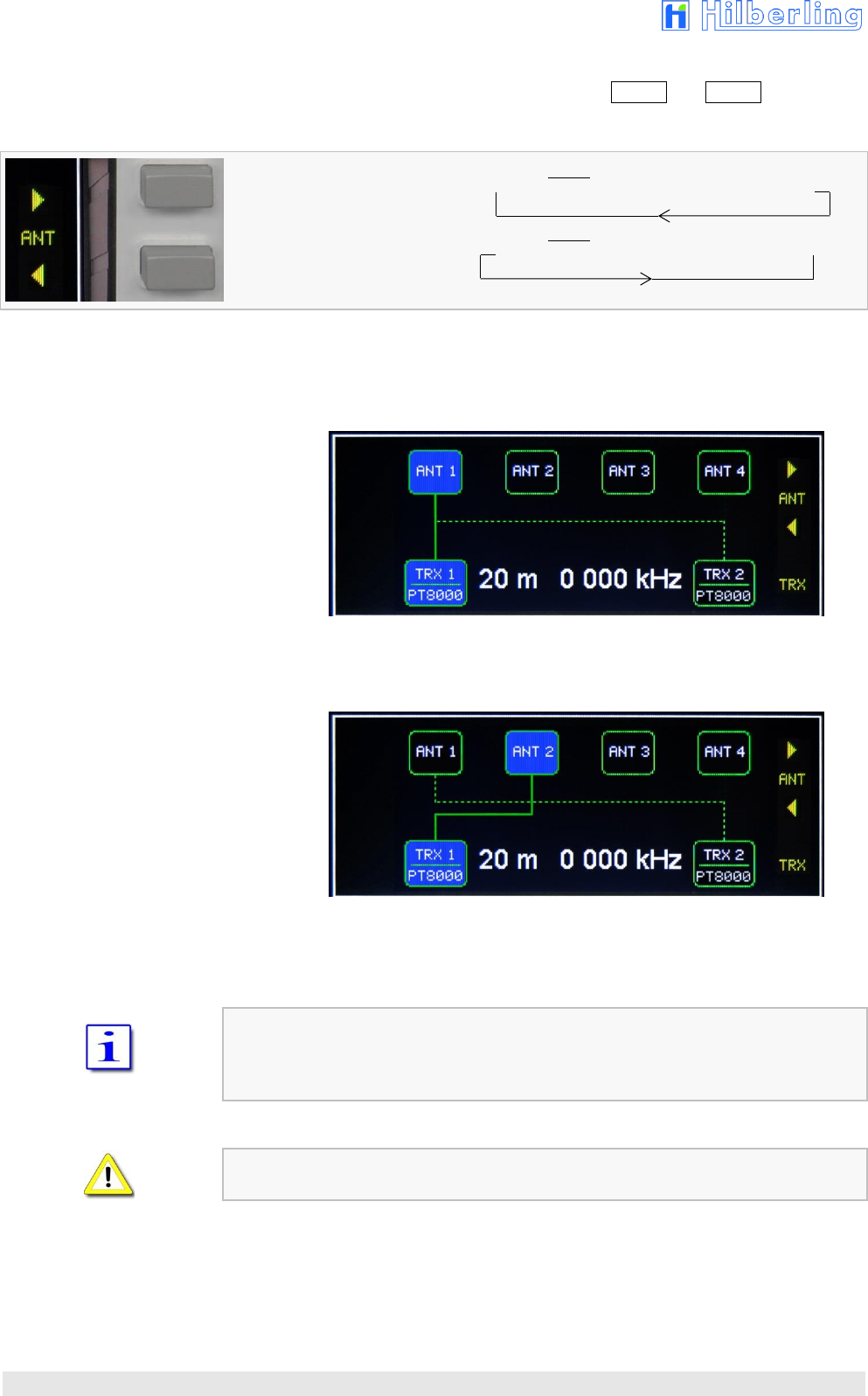
8.1 Antenna Allocation to Bands
One of the four antenna connectors can be allocated to each amateur radio band
supported by HPA-8000B-54 (s. Appendix A2). There is a particular allocation for
each transceiver connector TRX 1and TRX 2.
After initial power on antenna connector ANT 1 is allocated to all bands for both
transceiver connectors.
Allocation takes place for the current active transceiver connector at a time:
1. Pushing softkey TRX (on default screen – without menu) to select that
transceiver connector (= switching active, TRX 1 / TRX 2), for which the
allocation of a band to a antenna connector is to be carried out.
When active, the indication is shown by a blue background.
Fig. 8–1: Antenna Allocation – Toggle the active Transceiver
Toggle active transceiver (or TRX connector):
TRX 1: inactive / TRX 2: active (and vice versa, see Sec. 7.1).
When automatic or manual antenna tuning is activated (Sec. 8.4 u. 8.5), changing of
the transceiver connector is not possible (active/inactive).
2. When the allocated Transceiver (Sec.7.2) is connected to the HPA-8000B-54
and powered on, and the communication link is set up properly so that LED
REMOTE lights up at HPA-8000B-54, the band will be selected at the
allocated transceiver.
The LED of the appropriate band button of the HPA-8000B-54 lights up.
Continue with point 4.
3. When a communication link was not set up, and LED REMOTE at the
HPA-8000B-54 front panel is off, band selection will be done local at
HPA-8000B-54 (cluster HF-Band and VHF).
The LED on the selected band button lights up.
Band selection is only possible when the HPA-8000B-54 is not in REMOTE mode
(LED REMOTE is off) (cp. point 2.).
26
4. Select antenna connector by using softkeys ANT ␐ and ANT ␑.
Fig. 8–2: Antenna Allocation – Change of Antenna Connector
Cyclic change of antenna connector of the active transceiver in ascending order,
starting at current Position. ANT 1 ANT 2 ANT 3 ANT 4
Cyclic change of antenna connector of the active transceiver in descending order,
starting at current Position. ANT 1 ANT 2 ANT 3 ANT 4
.
The graphical depiction of the antenna allocation varies accordingly:
Fig. 8–3: Antenna Allocation – Factory Setting
Fig. 8–4: Antenna Allocation – Variation Example
The antenna allocation will be stored permanently and without confirmation.
For the non-active (as well as for the active) transceiver is true:
Assumed the communication link to the HPA-8000B-54 is set properly the change of
the used antenna connector caused by a band switch will be depicted on the display
(non-active TRX = dotted line).
When automatic or manual antenna tuning is activated (Sec. 8.4 u. 8.5), changing of
the antenna connector is not possible.

HPA-8000B-54 Operating Manual v1.03.18 27
8.2 Antenna and Antenna Tuner – basic Considerations
Standing wave ratio (SWR) may increase significantly when using an antenna outside
of the specific frequency range for which it is tuned. The power amplifier will operate
at peak performance only when its load is resistive – i.e. the SWR is close to 1.0.
The HPA-8000B-54 is equipped with an automatic antenna tuner (ATU) which does
not actually tune the antenna. The ATU instead matches the feed line to the final
amplifiers so they always “see” a SWR close to 1.0.
The ATU has its limits – tuning mismatches with SWR greater than 3.0 become difficult
and will exceed the capabilities of the ATU. Using a tuned or resonant antenna with
50 Ohm impedance at the feed point for the specific frequencies is highly
recommended. The purpose of the ATU is to ensure that a resonant antenna can be
used at the limits of the band selected with optimum performance of both
HPA-8000B-54 and antenna system.
Never try to hook up a symmetrical open feeder line (balanced, twin-lead, ladder line
etc.) directly to the HPA-8000B-54. Instead use 50 Ohm coaxial feeders only. The
connectors supplied on the HPA-8000B-54 are all Type N.
With the ATU it is acceptable to use a broadband antenna system like a log periodic
or T2FD system which trade wide bandwidth for an SWR ranging as high as 3.0.
8.3 Antenna Tuner
The HPA-8000B-54 is equipped with an antenna tuner, which allows automatic tuning
(button START) as well as manual tuning (button MANUAL) on the HF amateur radio
bands within range 1.8 to 29.7 MHz.
Each band is divided into subbands. For each of these subbands and for each of the
four antenna connectors a separate filter setting. The number of subbands varies from
Band to Band (s. Sec. A2.3 Appendix).
It is recommended to tune first automatically (see Sec. 8.4) and possibly cary out
subsequently a manual „fine tuning“ (Sec. 8.5).
Both for tuning as well as for using the tuner settings when transmitting the band and
frequency data of the connected transceiver will be needed.
When the allocated Transceiver (Sec.7.2) is connected to the HPA-8000B-54 and
powered on, and the communication link is set up properly so that LED REMOTE lights
up at HPA-8000B-54, the band and frequency data sent by the transceiver will be
shown on the display and the LED of the appropriate band button will light up.
In case a transceiver is connected without data communication link and then powered
on, a short CW PTT signal of low power is needed in order to read out the frequency
and band information by the internal frequency counter of the HPA-8000B-54.
In this configuration the LED REMOTE will remain off. Band and frequency data will be
depicted on the display and the LED of the appropriate band button will light up.
28
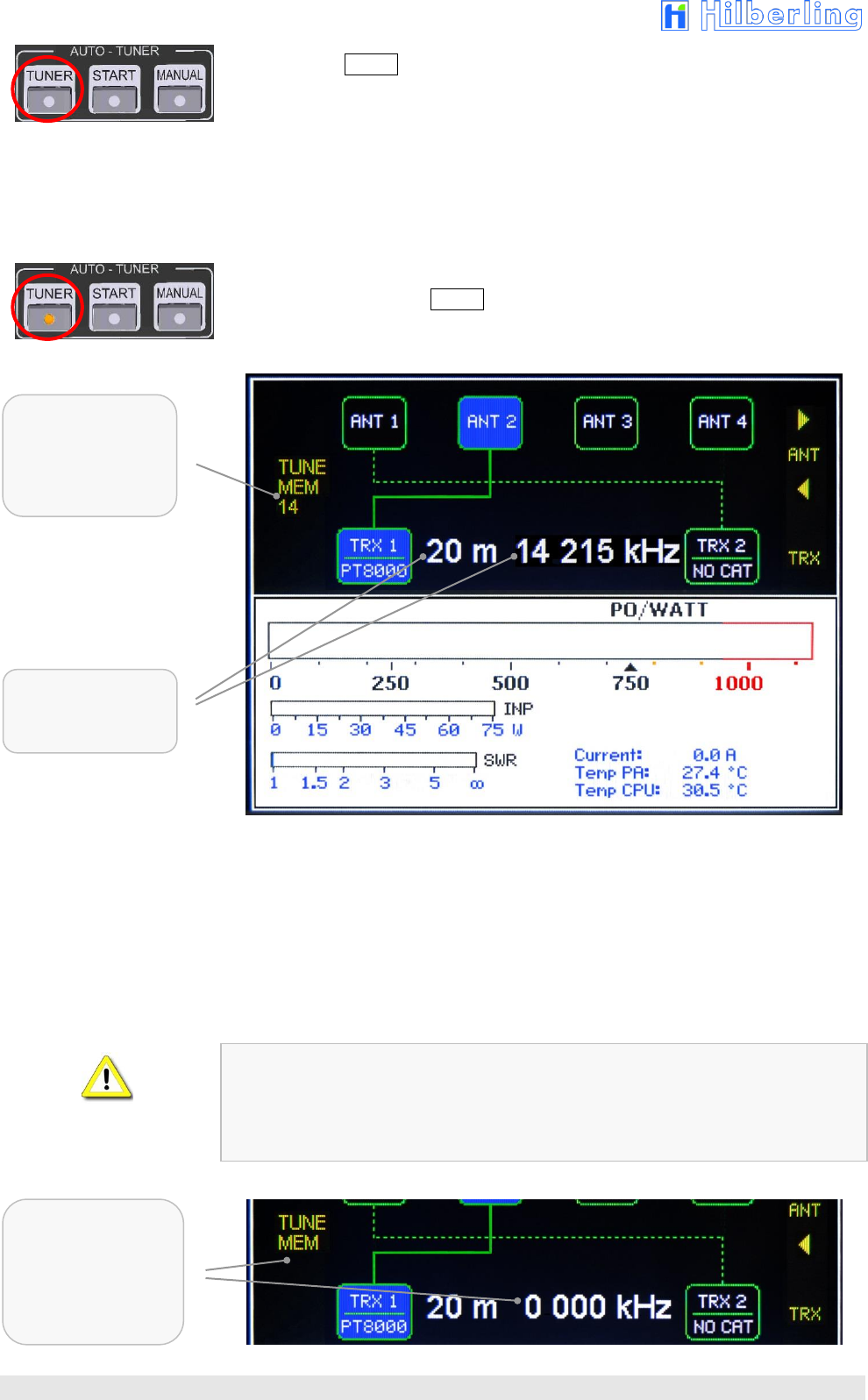
Pushing button TUNER in the cluster AUTO – TUNER will switch on the antenna tuner
(pushing again will switch off), the following will be shown:
The subband memory position corresponding to the current transceiver
frequency will be shown on display („TUNE MEM XY“; Tables of subbands see
Section A2.3 Appendix).
The color of the displayed subband varies:
Yellow Letters: This subband was not tuned yet
(= non-tuned harmonic filter is active).
Green Letters: This subband has been tuned
(= settings of an earlier tuning are active).
The LED of button TUNER will light up.
Fig. 8–5: Antenna Tuner activated – Showing Frequency Information
As mentioned at the beginning of this section, a frequency information is always
needed for tuning. This information can be communicated by:
Data connection from/to transceiver
(CAT link via D-Sub connection at J3 / J4);
CW signal from Transceiver
(Evaluation of the HF signals at J10 … J13 by internal frequency counter);
Data connection from/to PC (CAT remote control via USB connection J9).
When no frequency information is available at HPA-8000B-54 (no data
communication link to the transceiver; an evaluable HF signal has not received yet),
the display of „TUNE MEM“ will take place without designation of subband memory
position. In this case the standard values of the harmonic filter for this band defined by
hardware will be preselected (when OPERATE off) or switched (when OPERATE on).
Fig. 8–6: Antenna Tuner activated – no Frequency Information
Subband
Memory Position
yellow (not tuned)
or green (tuned)
Band and Frequency
Information by
Transceiver
Subband Memory
Position and TRX
Frequency
not displayed
(Band Selection at
HPA-8000B)
HPA-8000B-54 Operating Manual v1.03.18 29
8.4 Automatic Antenna Tuning
The automatic tuning proceeds as follows:
1. As described in section 7.2 the transceiver is powered on (receive mode),
band and frequency are selected at the transceiver and are recognized and
displayed by the HPA-8000B-54 (remote mode; LED REMOTE shines); the
tuner of the HPA-8000B-54 is activated (Sec. 8.3).
2. Preselect output power of the transceiver to a minimum (do not transmit yet
= PTT off).
3. Switch final PA of the HPA-8000B-54 active (button OPERATE in the cluster
FUNCTION, see Sec. 9).
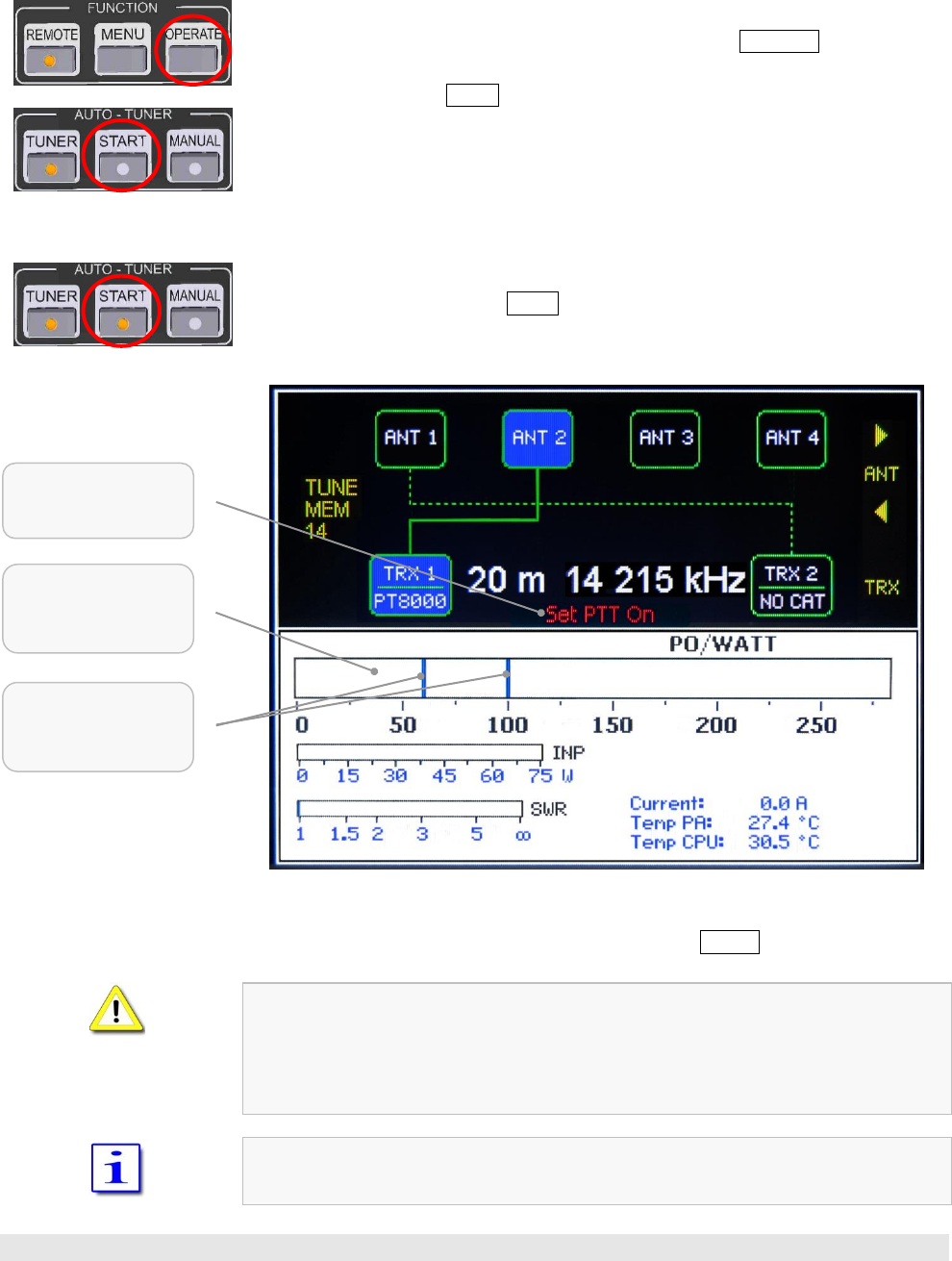
4. Pushing button START in the cluster AUTO – TUNER will select the automatic
tuning mode (pushing again will deselected the tuning mode):
The power meter for output power POUT changes to tuning mode
(250 Watt scale). Two lines (lower edge at 60 watt out and upper edge
at 100 watt out) mark the range of power within which it is possible to
tune the filters.
A message will be shown to set the transceiver to transmit mode
(„Set PTT On“).
The LED of button START will light up.
Fig. 8–7: Auto-Tuning activated „Set PTT On“
5. Select CW mode at the transceiver and activate PTT by minimum of power
permanently (e.g. Hilberling PT-8000A: button TX/ON).
It is recommended to start with a minimum of transceiver output power.
When output power of the HPA-8000B-54 exceeds 250 watt the tuning process
will abort and the automatic tuning mode will be deselected (button LED off).
Automatic tuning cannot be selected as long as the final PA is not activated
(OPERATE on).
In case there is shown a softkey menu or another screen than default screen they will
be hidden.
Message:
switch on PTT
Lower and upper
edge while
tuning procedure
Power Meter
Output Power POUT
in Tuning Mode
30
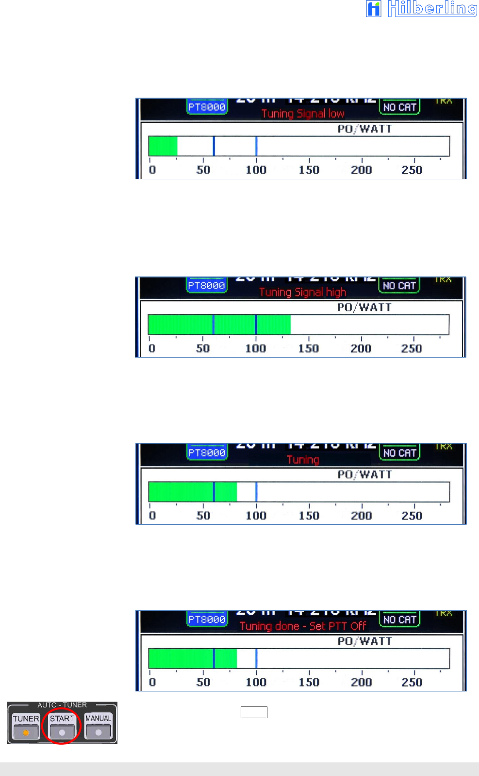
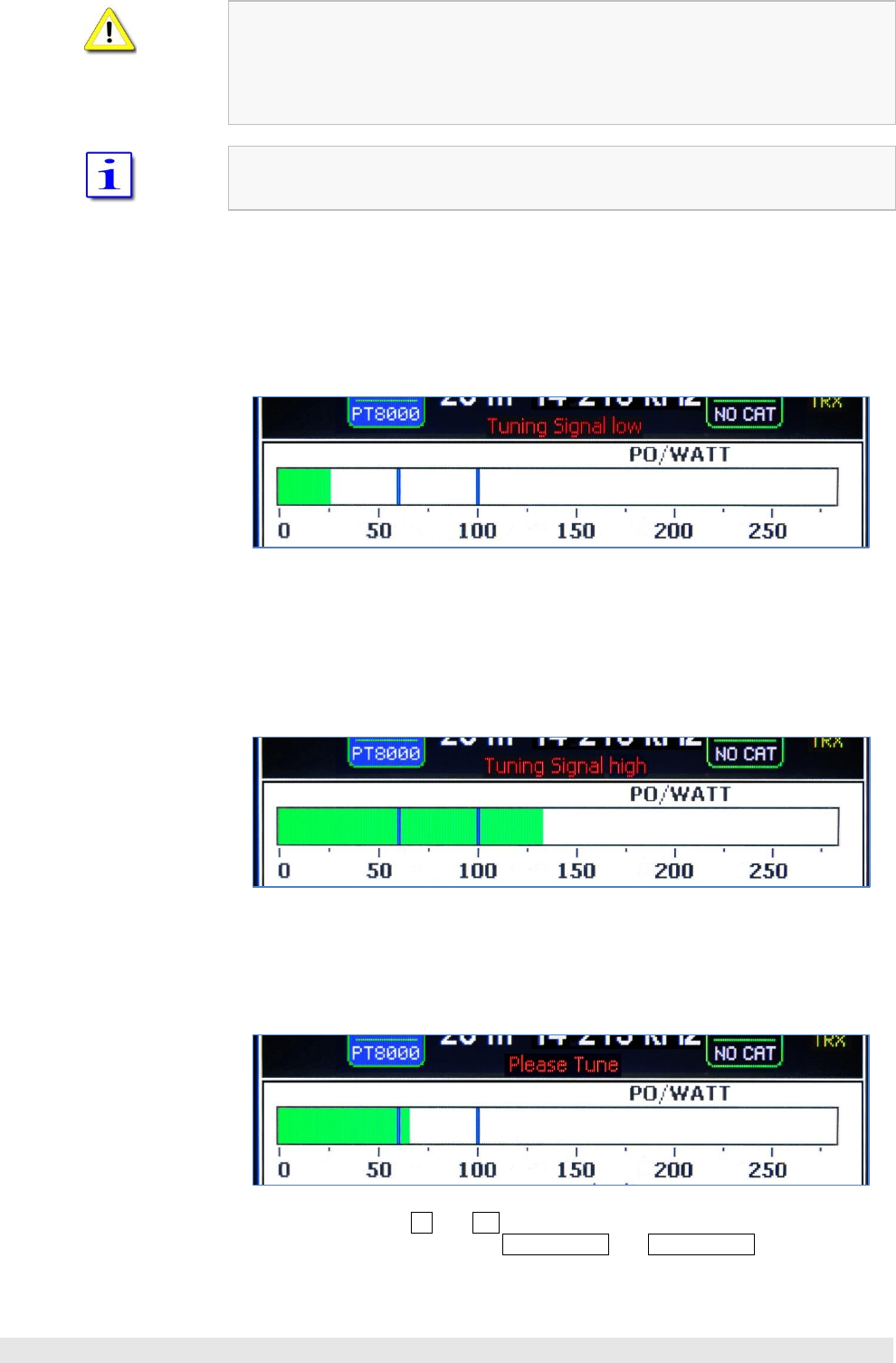
6. Increase transceiver output power slowly.
As long as the output power of the HPA-8000B-54 stays below the lower
tuning edge, the message „Tuning Signal low“ will be shown.
If so further increase transceiver power.
Fig. 8–8: Auto Tuning – Input Power too low „Tuning Signal low“
7. In case transceiver power it too high, and therefore the output power of the
HPA-8000B-54 is higher than upper tuning edge still before the tuning
procedure has been started, the message „Tuning Signal high“ will be shown.
If so decrease transceiver power.
Fig. 8–9: Auto Tuning – Input Power too high „Tuning Signal high“
8. In case the output power of the HPA-8000B-54 is within tuning range, the
tuning process will start automatically and the message „Tuning“ will be
shown. On the filter board the relays will be switched audible.
Fig. 8–10: Auto Tuning – Input Power ok „Tuning“
9. When the tuning process will be completed after a few seconds, the message
„Tuning done – set PTT off“ will be shown.
Now deactivate PTT at the transceiver.
Fig. 8–11: Auto Tuning finished „Tuning done“
10. The LED on button START goes off and – if this subband was tuned the first
time – the indicator TUNE MEM will change its color from yellow to green.
The new filter settings will be stored permanently and without confirmation.
HPA-8000B-54 Operating Manual v1.03.18 31
8.4.1 Error Messages when Tuning Process was aborted
In case transceiver power it too high, and therefore the output power of the HPA-
8000B-54 is higher than upper tuning edge after the tuning procedure has been
started, or a failure occurs in this phase, the tuning procedure will abort with the
message „Tuning Abort – Set PTT off“.
If so deactivate PTT and start the automatic tuning again.
Fig. 8–12: Auto-Tuning aborted „Tuning abort“
This message will also be shown when the automatic tuning procedure was aborted by
operator when pushing button START.
In this case the last memorized values are valid or (if no tuning was done before) the
values of the un-tuned harmonic filter.
Once the automatic tuning process has been started, a few more events can cause an
abort with one of the following error messages:
When the input power of the HPA-8000B-54 fluctuate too strongly while tuning, so
that tuning of the harmonic filter is no more possible, the procedure will abort with
message „INPUT UNSTABLE“:
Fig. 8–13: Auto Tuning – Input Power unstable „Input unstable“
In case the output power of the HPA-8000B-54 exceeds 250 watt while tuning, the
procedure will abort with message „OUTPUT OVERLOAD“:
Fig. 8–14: Auto Tuning – Output Power too high „Output Overload“
During the tuning process the TRX PTT signal must be activated permanently and
the output power of the HPA-8000B-54 must be between 60 und 100 watt.
As long as the LED in the button START shines (automatic tuning is activated),
softkey menu (MENU) cannot be called up.
32
8.5 Manual Antenna Tuning
The manual antenna tuning is done in the following steps:
1. As described in section 7.2 the transceiver is powered on (receive mode),
band and frequency are selected at the transceiver and are recognized and
displayed by the HPA-8000B-54 (remote mode; LED REMOTE shines); the
tuner of the HPA-8000B-54 is activated (Sec. 8.3).
2. Preselect output power of the transceiver to a minimum (do not transmit yet
= PTT off).
3. Switch final PA of the HPA-8000B-54 active (button OPERATE in the cluster
FUNCTION, see Sec. 9).
4. Pushing button MANUAL in the cluster AUTO – TUNER will select the manual
tuning mode (pushing again will deselected the tuning mode):
The power meter for output power POUT changes to tuning mode
(250 Watt scale). Two lines (lower edge at 60 watt out and upper edge
at 100 watt out) mark the range of power within which it is possible to
tune the filters.
Right below to output power meter – above displayed current and
temperature values – currently switched values of the harmonic filter
(Lout, Cout and CC) will be shown for the present subband.
Below, near right edge of the display, the softkey functions for setting the
center capacitance (= CC) of the harmonic filter will be shown.
A message will be shown to set the transceiver to TRX mode
(„Set PTT On“).
The LED of button MANUAL will light up.
Fig. 8–15: Manual Tuning activated „Set PTT On“
5. Set the transceiver to CW mode and permanently activate PTT with a
minimum of power (e.g. Hilberling PT-8000A: button TX/ON).
Message:
Switch on PTT
Lower and upper
edge while
tuning procedure
Power Meter
Output Power POUT
in Tuning Mode
Harmonic Filter:
Values Lout, Cout u. CC
for current Subband
Increase/decrease of
Center Capacitance
of Harmonic Filter
(by Softkeys)
HPA-8000B-54 Operating Manual v1.03.18 33
It is recommended to start with a minimum of transceiver output power.
If HPA-8000B-54s output power will exceed 250 watt the tuning procedure will
be aborted and the tuning mode will be deselected (button LED off).
Manual tuning cannot be selected as long as the final PA is not activated
(OPERATE on).
In case there is shown a softkey menu or another screen than default screen they will
be hidden.
6. Increase transceiver output power slowly.
As long as the output power of HPA-8000B-54 stays below the lower tuning
edge, the message „Tuning Signal low“ will be shown.
If so further increase transceiver power.
Fig. 8–16: Manual Tuning – Input Power too low „Tuning Signal low“
7. In case transceiver power it too high, and therefore the output power of HPA-
8000B-54 is higher than upper tuning edge, the message
„Tuning Signal high“ will be shown.
If so decrease transceiver power.
Fig. 8–17: Manual Tuning – Input Power too high „Tuning Signal high“
8. When output power of HPA-8000B-54 is within tuning range, the message
„Please Tune“ will be shown.
Fig. 8–18: Manual Tuning – Input Power ok „Please Tune“
Using buttons – and + located in the clusters „L – TUNE“ und „C –
TUNE“ and using softkeys CC-Tune and CC-Tune the filter values
of current subband now can be adjusted (see next page).
34
8.5.1 Manual L Tuning
Using buttons
–
und + in the cluster „L – TUNE“ the inductance on output side of
harmonic filter will be adjusted (labeled on display as LOUT).
–
Decreases output inductance of harmonic filter.
+ Increases output inductance of harmonic filter.
Increment 25 nH / 255 steps (values see Tab. A2-14 Appendix).
8.5.2 Manual C Tuning
Using buttons – and + in the cluster „C – TUNE“ the capacitance on output side of
harmonic filter will be adjusted (labeled on display as COUT).
–
Decreases output capacitance of harmonic filter.
+ Increases output capacitance of harmonic filter.
Increment 5 pF (approximated) / 255 steps (values see Tab. A2–14 Appendix)
8.5.3 Manual CC Tuning
Using softkeys CC–Tune and CC–Tune the center capacitance of harmonic
filter will be adjusted (labeled on display as CC).
Fig. 8–19: Manual Tuning – Center Capacitance CC
Increase center capacitance of harmonic filter.
Decrease center capacitance of harmonic filter.
Increment 10 pF (approximated) / 255 steps (Values see Tab. A2–14 Appendix)
9. Manual tuning will be finished by deactivating the PTT on connected
transceiver or by pushing button MANUAL. In the latter case the message
„Tuning done – Set PTT off“ (Fig. 8–11) will be shown on display to remind
the deactivation of PTT on transceiver.
10. The LED on button MANUAL goes off and – if this subband was tuned the first
time – the indicator TUNE MEM will change its color from yellow to green.
The new filter settings will be stored permanently and without any confirmation.
During the tuning process the TRX PTT signal must be activated permanently and
the output power of the HPA-8000B-54 must be between 60 und 100 watt.
As long as the LED on button MANUAL shines (manual tuning is activated),
softkey menu (MENU) cannot be called up.
HPA-8000B-54 Operating Manual v1.03.18 35
9 INTERNAL FINAL PA OPERATE
When power on the HPA-8000B-54 the final power amplifier is set to bypass mode,
i.e. it is switched inactive, correspondingly LED READY does not shine.
The complete control of the filter board is deactivated as well. When band change
occurs – whether local controlled or remote controlled by connected transceiver via
communication link – the filters will not switched.
Pushing button OPERATE in the cluster FUNCTION will activate the final power
amplifier (pushing again will put it back into the bypass mode):
Filter board control will be activated.
When the PA receives a PTT signal from connected and activated transceiver,
incoming HF signals will be amplified and sent according to current antenna
routing to the active antenna connector.
LED READY will light up.
The PA only can be activated when the PTT signal of the connected transceiver is
switched off.
The PA must be activated hence the automatic or manual tuning mode can be
selected.
The PA cannot be deactivated as long as automatic or manual tuning mode is
selected.
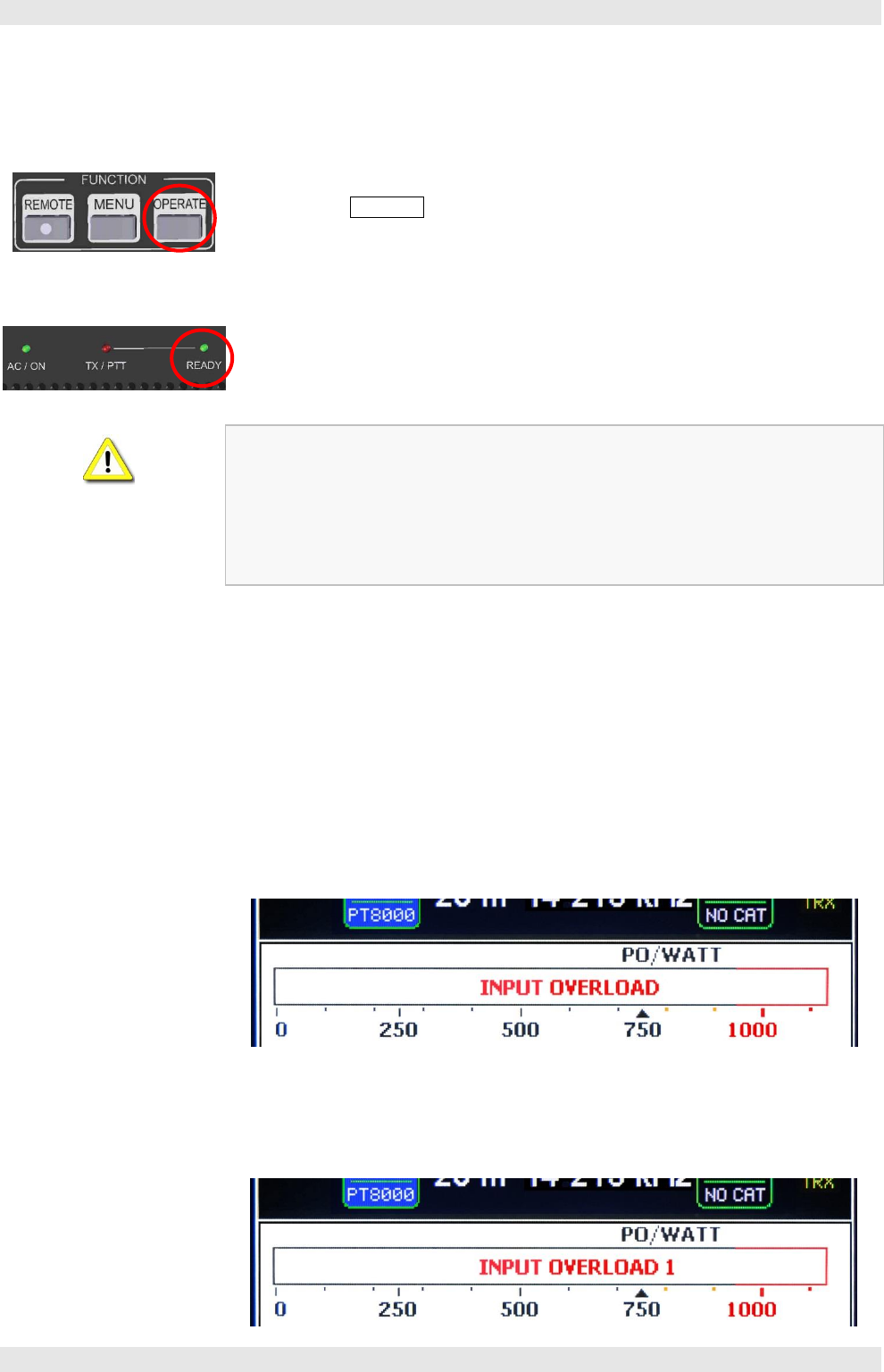
9.1 Error Messages when Final PA was deactivated.
Once an overload inside final amplifier occurs while operating HPA-8000B-54, the
internal PTT will be switched off and an appropriated error message will be shown on
display for 1 to 2 seconds. To reset the HPA-8000B-54 deactivate PTT signal on
transceiver.
In case input power is too high and the final amplifier is switched off by software
(details Tab. A2–15 Appendix), message „INPUT OVERLOAD“ will be shown on
display.
Fig. 9–2: Input Overload
In case input power is too high and the final amplifier is switched off by hardware,
message „INPUT OVERLOAD 1“ will be shown on display.
Fig. 9–1: Input Overload 1
36
In case output power is higher than 1050 Watt for more than 500 ms, message
„OUTPUT OVERLOAD“ will be shown.
Fig. 9–3: Output Overload
In case output power is higher than 1300 Watt for more than 100 ms, message
„OUTPUT OVERLOAD MID“ will be shown.
Fig. 9–4: Ouput Overload Mid
In case output power is higher than 1500 Watt, the final amplifier will be switched off
immediately and message „OUTPUT OVERLOAD HIGH“ will be shown.
Fig. 9–5: Ouput Overload High
In case output current is higher than 42 Ampere for more than 1000 ms, message
„CURRENT OVERLOAD“ will be shown.
Fig. 9–6: Current Overload
9.2 ALC Connection
It is recommended to prepare an ALC connection between connected transceiver/s
and HPA-8000B-54 (9-pin D-Sub J1/J2 Pin 6 or RCA J7/J8) to prevent the power
amplifier from overload.
For adjustment of ALC threshold trim pots PJ7 / PJ8 are intended. When adjustment is
done the ALC meter on the transceiver can be used for optical control.

HPA-8000B-54 Appendix v1.03.18 37
APPENDIX
A1 Technical Documents
A2 Customer Information

38
A1 TECHNICAL DOCUMENTS
A1.1 Technical Data
Tab. A1-1: Technical Data
Output Power ( FM / AM / SSB / CW )
1
kW
Add. PA Output (Predistortion Feedback Channel)
–60
dBc ATT.
Amateur Radio Bands
160
m – 6
m ( 1.8 – 54
MHz ) s. Tab A2–2
Input Power
typ. 50
W / 1
kW RF Out
Transceiver Connectors
2
Antenna Connectors
4
Antenna Tuner fully automatic
1.8 – 29.7
MHz ( max. SWR 3:1 )
Remote Control by Transceiver ( CAT )
⬧ Band Switch
⬧ Frequency Display
CAT Interfaces
⬧ RS232
⬧ Band Data 4bit
⬧ CI-V
⬧ Band Voltage
Manual Control
⬧ Band Buttons
⬧ PTT Input ( RCA )
⬧ ALC Input ( RCA )
PC Interface (Programming / Update)
USB / RS232
Protective circuits
⬧ Overcurrent
⬧ SWR
⬧ Temperature
⬧ Input Power
⬧ Output Power
Power Supply
Internal Power Supply Unit
200 – 260
V / 50 – 60
Hz / 13 A
Dimensions
approx. 425 x 459 x 173
mm ( W x D x H )
( approx. 16.75 x 18.1 x 6.8’’ )
Weight
19.8
kg ( 43.7
lbs )
Technical specs subject to change without notice
HPA-8000B-54 Appendix A2 v1.03.18 39
A1.2 Amateur Radio Bands
Tab. A1–2: Frequency Bands HF
Button
Band
Sign
Frequency Range
1.8 1
160 m
MF
1.8101 /1.8002,3
...
2.000 MHz
3.5 2
80 m
HF
3.500
...
3.8001 / 4.0002 / 3.9003 MHz
7.0 3
40 m
7.000
...
7.2001 / 7.3002,3MHz
10 4
30 m
10.100
...
10.150 MHz
14 5
20 m
14.000
...
14.350 MHz
18 6
17 m
18.068
...
18.168 MHz
21 7
15 m
21.000
...
21.450 MHz
24 8
12 m
24.890
...
24.990 MHz
28 9
10 m
28.000
...
29.700 MHz
Tab. A1–3: Frequency Band VHF
Button
Band
Sign
Frequency Range
50 0
6 m
VHF
50.000
...
52.0001 / 54.0002,3 MHz
52 MHz
1 = IARU Region 1 2 = IARU Region 2 3 = IARU Region 3
1 = IARU Region 1 2 = IARU Region 2 3 = IARU Region 3

40
A1.3 Subbands Antenna Tuning
Tab. A1–4: Subbands 160m
Frequency [kHz]
TUNE MEM
[1]
[2]
[3]
[4]
[5]
[6]
[7]
[8]
[9]
Lower
1780
1784
1788
1792
1796
1800
1804
1808
1812
Middle
1782
1786
1790
1794
1798
1802
1806
1810
1814
Upper
1784
1788
1792
1796
1800
1804
1808
1812
1816
TUNE MEM
[10]
[11]
[12]
[13]
[14]
[15]
[16]
[17]
[18]
[19]
Lower
1816
1820
1824
1828
1832
1836
1840
1844
1848
1852
Middle
1818
1822
1826
1830
1834
1838
1842
1846
1850
1854
Upper
1820
1824
1828
1832
1836
1840
1844
1848
1852
1856
TUNE MEM
[20]
[21]
[22]
[23]
[24]
[25]
[26]
[27]
[28]
[29]
Lower
1856
1860
1864
1868
1872
1876
1880
1884
1888
1892
Middle
1858
1862
1866
1870
1874
1878
1882
1886
1890
1894
Upper
1860
1864
1868
1872
1876
1880
1884
1888
1892
1896
TUNE MEM
[30]
[31]
[32]
[33]
[34]
[35]
[36]
[37]
[38]
[39]
Lower
1896
1900
1904
1908
1912
1916
1920
1924
1928
1932
Middle
1898
1902
1906
1910
1914
1918
1922
1926
1930
1934
Upper
1900
1904
1908
1912
1916
1920
1924
1928
1932
1936
TUNE MEM
[40]
[41]
[42]
[43]
[44]
[45]
[46]
[47]
[48]
[49]
Lower
1936
1940
1944
1948
1952
1956
1960
1964
1968
1972
Middle
1938
1942
1946
1950
1954
1958
1962
1966
1970
1974
Upper
1940
1944
1948
1952
1956
1960
1964
1968
1972
1976
TUNE MEM
[50]
[51]
[52]
[53]
[54]
[55]
[56]
[57]
[58]
[59]
Lower
1976
1980
1984
1988
1992
1996
2000
2004
2008
2012
Middle
1978
1982
1986
1990
1994
1998
2002
2006
2010
2014
Upper
1980
1984
1988
1992
1996
2000
2004
2008
2012
2016
TUNE MEM
[60]
Lower
2016
Middle
2018
Upper
2020
Number of Subbands:60
Increment: 4 kHz

HPA-8000B-54 Appendix A2 v1.03.18 41
Tab. A1–5: Subbands 80m
Frequency [kHz]
TUNE MEM
[1]
[2]
[3]
[4]
[5]
[6]
[7]
[8]
[9]
Lower
3460
3470
3480
3490
3500
3510
3520
3530
3540
Middle
3465
3475
3485
3495
3505
3515
3525
3535
3545
Upper
3470
3480
3490
3500
3510
3520
3530
3540
3550
TUNE MEM
[10]
[11]
[12]
[13]
[14]
[15]
[16]
[17]
[18]
[19]
Lower
3550
3560
3570
3580
3590
3600
3610
3620
3630
3640
Middle
3555
3565
3575
3585
3595
3605
3615
3625
3635
3645
Upper
3560
3570
3580
3590
3600
3610
3620
3630
3640
3650
TUNE MEM
[20]
[21]
[22]
[23]
[24]
[25]
[26]
[27]
[28]
[29]
Lower
3650
3660
3670
3680
3690
3700
3710
3720
3730
3740
Middle
3655
3665
3675
3685
3695
3705
3715
3725
3735
3745
Upper
3660
3670
3680
3690
3700
3710
3720
3730
3740
3750
TUNE MEM
[30]
[31]
[32]
[33]
[34]
[35]
[36]
[37]
[38]
[39]
Lower
3750
3760
3770
3780
3790
3800
3810
3820
3830
3840
Middle
3755
3765
3775
3785
3795
3805
3815
3825
3835
3845
Upper
3760
3770
3780
3790
3800
3810
3820
3830
3840
3850
TUNE MEM
[40]
[41]
[42]
[43]
[44]
[45]
[46]
[47]
[48]
[49]
Lower
3850
3860
3870
3880
3890
3900
3910
3920
3930
3940
Middle
3855
3865
3875
3885
3895
3905
3915
3925
3935
3945
Upper
3860
3870
3880
3890
3900
3910
3920
3930
3940
3950
TUNE MEM
[50]
[51]
[52]
[53]
[54]
[55]
[56]
[57]
[58]
Lower
3950
3960
3970
3980
3990
4000
4010
4020
4030
Middle
3955
3965
3975
3985
3995
4005
4015
4025
4035
Upper
3960
3970
3980
3990
4000
4010
4020
4030
4040
Number of Subbands:58
Increment: 10 kHz
42
Tab. A1–6: Subbands 40m
Frequency [kHz]
TUNE MEM
[1]
[2]
[3]
[4]
[5]
[6]
[7]
[8]
[9]
Lower
6950
6960
6970
6980
6990
7000
7010
7020
7030
Middle
6955
6965
6975
6985
6995
7005
7015
7025
7035
Upper
6960
6970
6980
6990
7000
7010
7020
7030
7040
TUNE MEM
[10]
[11]
[12]
[13]
[14]
[15]
[16]
[17]
[18]
[19]
Lower
7040
7050
7060
7070
7080
7090
7100
7110
7120
7130
Middle
7045
7055
7065
7075
7085
7095
7105
7115
7125
7135
Upper
7050
7060
7070
7080
7090
7100
7110
7120
7130
7140
TUNE MEM
[20]
[21]
[22]
[23]
[24]
[25]
[26]
[27]
[28]
[29]
Lower
7140
7150
7160
7170
7180
7190
7200
7210
7220
7230
Middle
7145
7155
7165
7175
7185
7195
7205
7215
7225
7235
Upper
7150
7160
7170
7180
7190
7200
7210
7220
7230
7240
TUNE MEM
[30]
[31]
[32]
[33]
[34]
[35]
[36]
[37]
[38]
[39]
Lower
7240
7250
7260
7270
7280
7290
7300
7310
7320
7330
Middle
7245
7255
7265
7275
7285
7295
7305
7315
7325
7335
Upper
7250
7260
7270
7280
7290
7300
7310
7320
7330
7340
TUNE MEM
[40]
Lower
7340
Middle
7345
Upper
7350
Number of Subbands:40
Increment: 10 kHz
Tab. A1–7: Subbands 30m
Frequency [kHz]
TUNE MEM
[1]
[2]
[3]
[4]
[5]
[6]
[7]
[8]
[9]
Lower
10050
10070
10090
10110
10130
10150
10170
10190
10210
Middle
10060
10080
10100
10120
10140
10160
10180
10200
10220
Upper
10070
10090
10110
10130
10150
10170
10190
10210
10230
TUNE MEM
[10]
Lower
10230
Middle
10240
Upper
10250
Number of Subbands:10
Increment: 20 kHz

HPA-8000B-54 Appendix A2 v1.03.18 43
Tab. A1–8: Subbands 20m
Frequency [kHz]
TUNE MEM
[1]
[2]
[3]
[4]
[5]
[6]
[7]
[8]
[9]
Lower
13950
13970
13990
14010
14030
14050
14070
14090
14110
Middle
13960
13980
14000
14020
14040
14060
14080
14100
14120
Upper
13970
13990
14010
14030
14050
14070
14090
14110
14130
TUNE MEM
[10]
[11]
[12]
[13]
[14]
[15]
[16]
[17]
[18]
[19]
Lower
14130
14150
14170
14190
14210
14230
14250
14270
14290
14310
Middle
14140
14160
14180
14200
14220
14240
14260
14280
14300
14320
Upper
14150
14170
14190
14210
14230
14250
14270
14290
14310
14330
TUNE MEM
[20]
[21]
[22]
[23]
[24]
[25]
Lower
14330
14350
14370
14390
14410
14430
Middle
14340
14360
14380
14400
14420
14440
Upper
14350
14370
14390
14410
14430
14450
Number of Subbands:25
Increment: 20 kHz
Tab. A1–9: Subbands 17m
Frequency [kHz]
TUNE MEM
[1]
[2]
[3]
[4]
[5]
[6]
[7]
Lower
18050
18070
18090
18110
18130
18150
18170
Middle
18060
18080
18100
18120
18140
18160
18180
Upper
18070
18090
18110
18130
18150
18170
18190
Number of Subbands: 7
Increment: 20 kHz
44
Tab. A1–10: Subbands 15m
Frequency [kHz]
TUNE MEM
[1]
[2]
[3]
[4]
[5]
[6]
[7]
[8]
[9]
Lower
20950
20970
20990
21010
21030
21050
21070
21090
21110
Middle
20960
20980
21000
21020
21040
21060
21080
21100
21120
Upper
20970
20990
21010
21030
21050
21070
21090
21110
21130
TUNE MEM
[10]
[11]
[12]
[13]
[14]
[15]
[16]
[17]
[18]
[19]
Lower
21130
21150
21170
21190
21210
21230
21250
21270
21290
21310
Middle
21140
21160
21180
21200
21220
21240
21260
21280
21300
21320
Upper
21150
21170
21190
21210
21230
21250
21270
21290
21310
21330
TUNE MEM
[20]
[21]
[22]
[23]
[24]
[25]
[26]
[27]
[28]
[29]
Lower
21330
21350
21370
21390
21410
21430
21450
21470
21490
21510
Middle
21340
21360
21380
21400
21420
21440
21460
21480
21500
21520
Upper
21350
21370
21390
21410
21430
21450
21470
21490
21510
21530
TUNE MEM
[30]
Lower
21530
Middle
21540
Upper
21550
Number of Subbands:30
Increment: 20 kHz
Tab. A1–11: Subbands 12m
Frequency [kHz]
TUNE MEM
[1]
[2]
[3]
[4]
[5]
[6]
[7]
[8]
[9]
Lower
24855
24875
24895
24915
24935
24955
24975
24995
25015
Middle
24865
24885
24905
24925
24945
24965
24985
25005
25025
Upper
24875
24895
24915
24935
24955
24975
24995
25015
25035
TUNE MEM
[10]
[11]
Lower
25035
25055
Middle
25045
25065
Upper
25055
25075
Number of Subbands:11
Increment: 20 kHz
HPA-8000B-54 Appendix A2 v1.03.18 45
Tab. A1–12: Subbands 10m
Frequency [kHz]
TUNE MEM
[1]
[2]
[3]
[4]
[5]
[6]
[7]
[8]
[9]
Lower
28000
28040
28080
28120
28160
28200
28240
28280
28320
Middle
28020
28060
28100
28140
28180
28220
28260
28300
28340
Upper
28040
28080
28120
28160
28200
28240
28280
28320
28360
TUNE MEM
[10]
[11]
[12]
[13]
[14]
[15]
[16]
[17]
[18]
[19]
Lower
28360
28400
28440
28480
28520
28560
28600
28640
28680
28720
Middle
28380
28420
28460
28500
28540
28580
28620
28660
28700
28740
Upper
28400
28440
28480
28520
28560
28600
28640
28680
28720
28760
TUNE MEM
[20]
[21]
[22]
[23]
[24]
[25]
[26]
[27]
[28]
[29]
Lower
28760
28800
28840
28880
28920
28960
29000
29040
29080
29120
Middle
28780
28820
28860
28900
28940
28980
29020
29060
29100
29140
Upper
28800
28840
28880
28920
28960
29000
29040
29080
29120
29160
TUNE MEM
[30]
[31]
[32]
[33]
[34]
[35]
[36]
[37]
[38]
[39]
Lower
29160
29200
29240
29280
29320
29360
29400
29440
29480
29520
Middle
29180
29220
29260
29300
29340
29380
29420
29460
29500
29540
Upper
29200
29240
29280
29320
29360
29400
29440
29480
29520
29560
TUNE MEM
[40]
[41]
[42]
[43]
[44]
[45]
Lower
29560
29600
29640
29680
29720
29760
Middle
29580
29620
29660
29700
29740
29780
Upper
29600
29640
29680
29720
29760
29800
Number of Subbands:45
Increment: 40 kHz
A1.4 Switchable L and C Elements Antenna Tuning
Tab. A1–13: Switchable Inductances und Capacitances Harmonic Filter
ID
[1]
[2]
[3]
[4]
[5]
[6]
[7]
[8]
LOUT
[nH]
25
50
100
200
400
800
1600
3200
COUT
[pF]
5
10
22
47
82
180
560
1200
CC
[pF]
10
20
40
94
164
300
940
2000
A1.5 Switch-off Criteria for INPUT OVERLOAD
Tab. A1–14: Switch-off Criteria for Input Overload
Error Message
typ. Input Power
Band
PIN,max
Input Overload
50 W
all
TBD
46
A1.6 Connecting Options
Tab. A1–15: Connecting Options TRX Setup
CAT Type
TRX Model
Baud Rate
TRX Connector
displayed
HILBERLING
PT8000
9600, 19200, 38400, 57600, 4800
PT8000
KENWOOD
All
9600, 19200, 38400, 57600, 4800
Kenwood
ICOM
CI-V
9600, 19200, 38400, 57600, 4800
ICOM
Band Voltage
---
YAESU
CAT 1
--- --- --- --- 4800
YAESU
CAT 2
9600, 19200, 38400, 57600, 4800
Band Data
---
FlexRadio
FLEX-6000
9600, 19200, 38400, 57600, 4800
FLEX-6k
ELECRAFT
K3
9600, 19200, 38400, 57600, 4800
K3
TENTEC
ORION II
--- --- --- 57600 ---
ORION II
REUTER
Band Data
---
REUTER
RS232
All
9600, 19200, 38400, 57600, 4800
RS232
NO CAT
---
---
NO CAT

HPA-8000B-54 Appendix A3 v1.03.18 47
A2 CUSTOMER INFORMATION
A2.1 User Information
A2.1.1 Declaration of Conformity (shortened version)
Hereby the Hilberling GmbH declares that the power amplifier HPA-8000B-54 is in compliance with the essential
requirements and other relevant provisions of Directive 1999/5/EC.
A full declaration of conformity is available in the original on the website www.hilberling.de.
A2.1.2 Note Amateur Radio Operation
The Hilberling GmbH is obliged as a manufacturer of transmitter devices to draw attention to the following legal
provisions:
The following restrictive conditions apply:
This device is intended for use by radio amateurs within the meaning of the law on amateur radio in the valid
amended. During operation of the device, the amateur radio law and supplementary laws and regulations must be
observed.
In Germany, as in other EU countries, special provisions for the acquisition, ownership and operation of amateur radio
apply. Acquisition and ownership of this device by unauthorized persons can already be punishable!
Even if the devices HPA-8000B-54 should have extended frequency ranges, radio amateurs may generally use only
the ham radio frequencies assigned to their country.
A2.2 Warranty Terms
Guarantee
For amateur radio power amplifier HPA-8000B-54 legal guarantee determinations apply only if the device is
operated in a manner corresponding to its intended use. This includes in particular the compliance with the operating
limits mentioned in this manual.

48
A2.3 Disposal Rules
Used electrical and electronic equipment must not longer be placed in unsorted municipal waste in accordance with
European standards. They must be collected separately and have to be disposed of by a public-service-disposer or
equivalent private companies.
The symbol of the crossed out wheeled bin on rear panel indicates the need for separate collection.
According to the German “Gesetz über das Inverkehrbringen, die Rücknahme und die umweltverträgliche Entsorgung
von Elektro- und Elektronikgeräten“, short ElektroG, the Hilberling GmbH is registered by the Stiftung Elektro-Altgeräte
Register as a distributor of electrical and electronic equipment under WEEE registry number DE 19129052 and thus
participate in the common disposal of electrical and electronic waste.
If there are any questions, please contact Hilberling GmbH as follows:
by E-Mail info@hilberling.de
by Phone +49 (0) 4331-20171-0
by Fax +49 (0) 4331-20171-10
by Mail Hilberling GmbH
Heinrich-Hertz-Strasse 2
24790 Schacht-Audorf