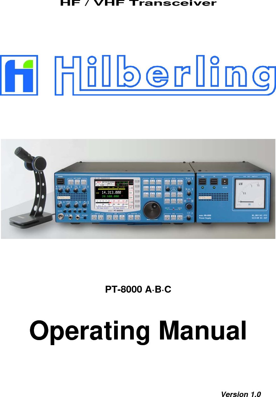
Hilberling RF Laboratories PT8000 HF/VHF Receiver User Manual 051208
Hilberling GmbH RF Laboratories HF/VHF Receiver 051208
UserManual.wiki
>
Hilberling RF Laboratories
>
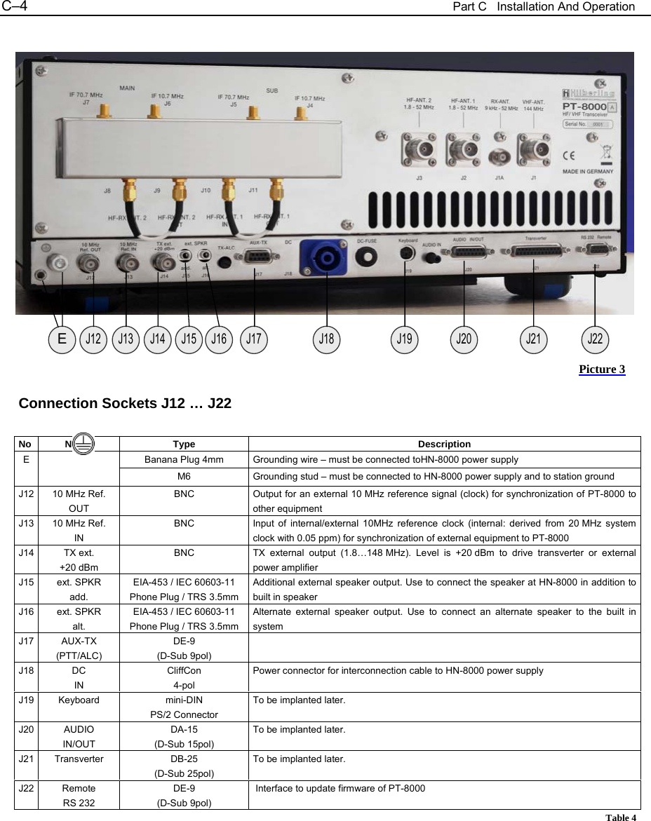
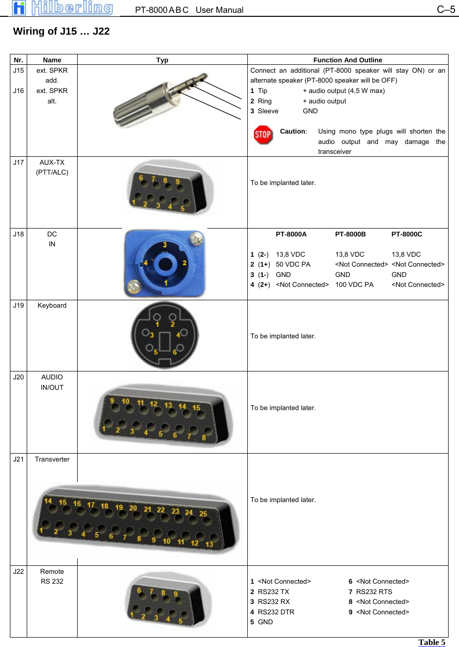
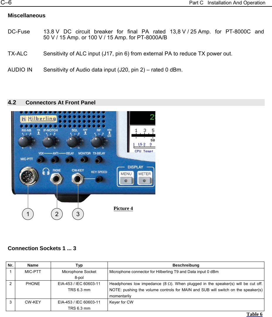
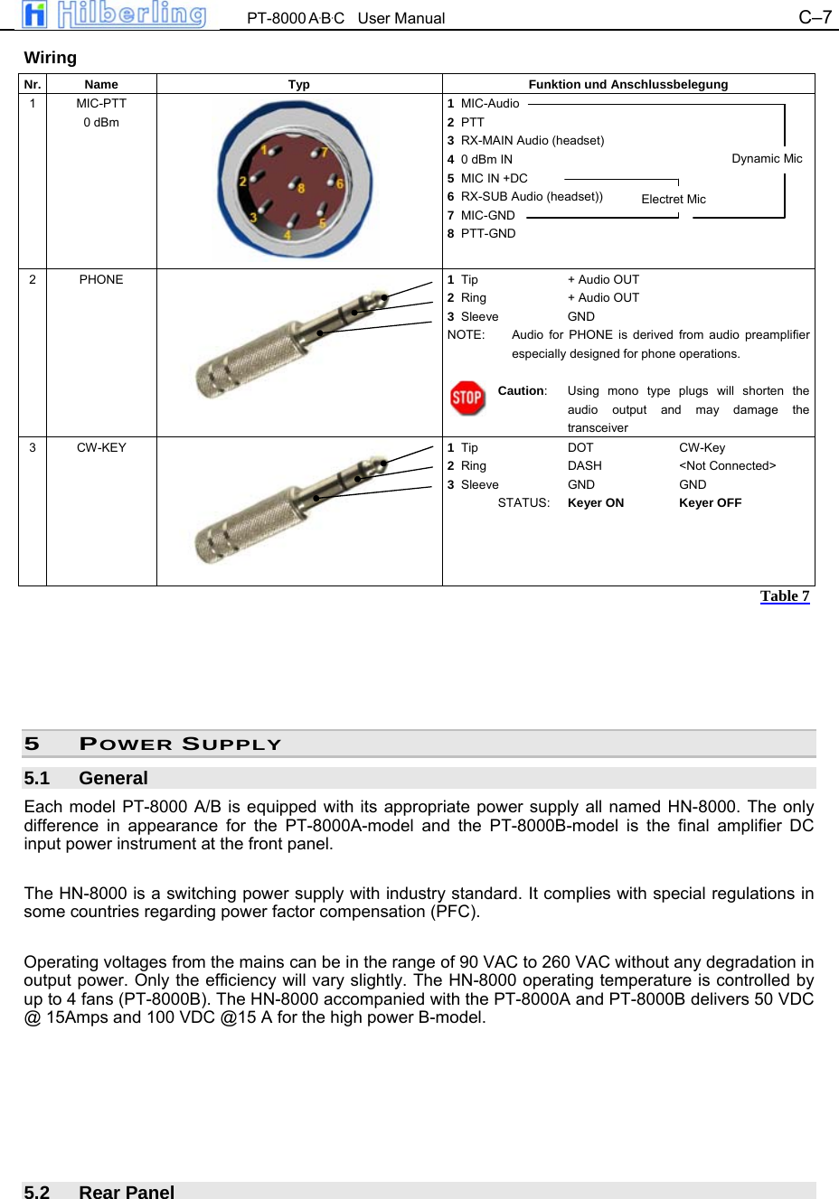
PT8000 User Manual
Users Manual Revised
Navigation menu
Upload a User Manual
Namespaces
Wiki Guide
HTML
PDF
Info
Views
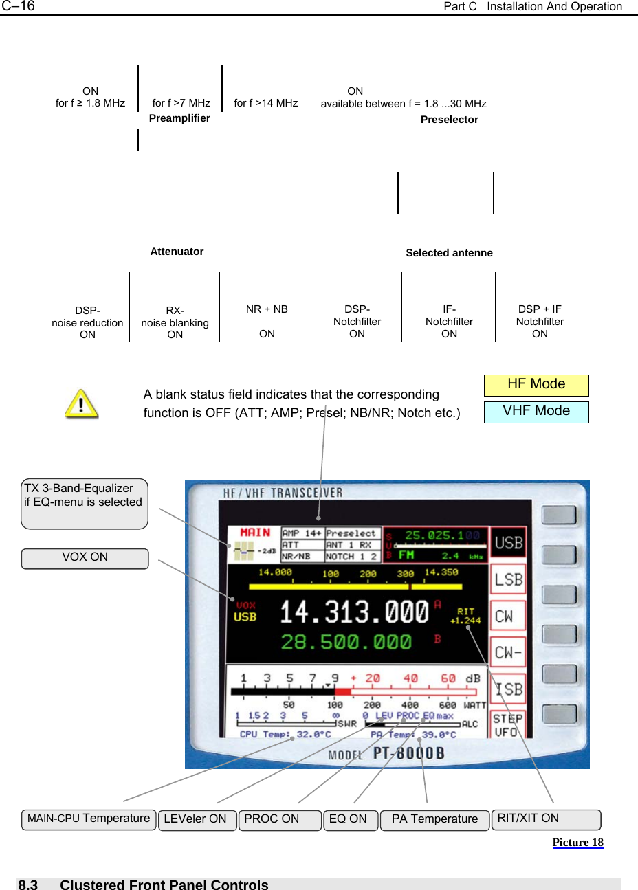
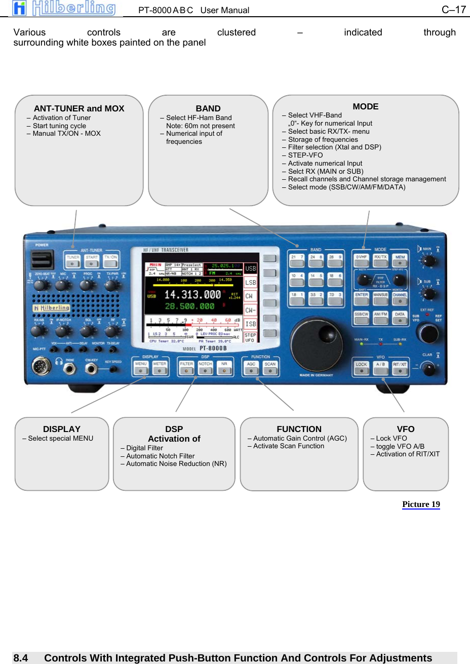
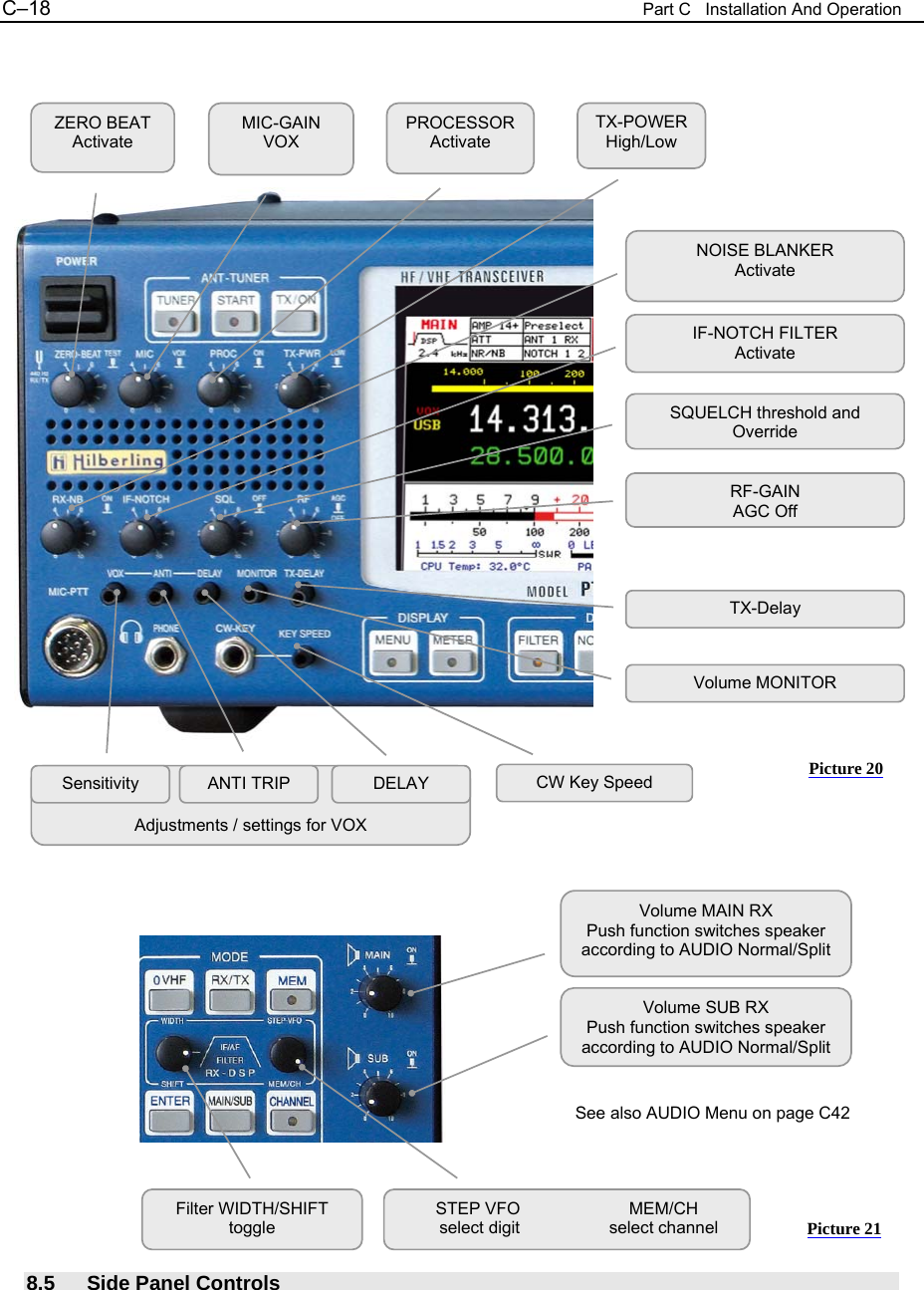
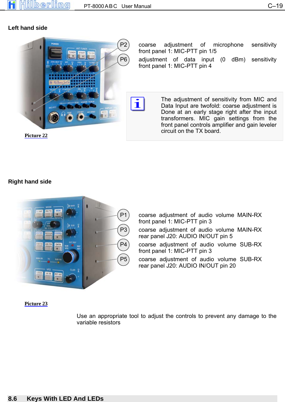
User Manual
Discussion / Help
Navigation