Hilberling RF Laboratories PT8000 HF/VHF Receiver User Manual 051208
Hilberling GmbH RF Laboratories HF/VHF Receiver 051208
Users Manual Revised
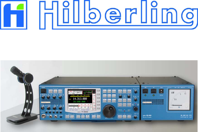
HF / VHF Transceiver
PT-8000 A·B·C
Operating Manual
Version 1.0
–– This page is intentionally blank ––

i
HF / VHF Transceiver
Hilberling PT-8000
A
/
B
/
C
Operating Manual
PT-8000, HN-8000 and T9
are
developed and manufactured in the EU
by
Hilberling GmbH
Kieler Strasse 53
24768 Rendsburg
Germany
Logo and name of Hilberling GmbH are registered trademarks

ii Precautions / Content
Important
Read and save this Operating Manual carefully before attempting to operate the HF/VHF PT-8000
transceiver. This manual contains important safety and operating instructions for the transceiver.
Precautions
WARNING HIGH VOLTAGE! NEVER touch an antenna or internal antenna connector during
transmission. This may result in an electrical shock or burn of your skin.
NEVER apply AC to the DC socket (13.8V and 100V for PT-8000 B) on the transceiver rear
panel. This will ruin the transceiver and may cause fire.
NEVER allow any object touch any internal parts or connectors on the rear panel of the
transceiver. This could cause electrical shock and severe injury.
NEVER expose the PT-8000 A/B to precipitation like rain or any liquid nor operate the
transceiver in excessively dusty or very humid environment.
NEVER allow children or any unauthorized persons to operate the transceiver.
AVOID placing and using the transceiver in areas with temperatures below -15°C or above +50°C.
AVOID placing the transceiver against a wall. This may inhibit proper air circulation and could cause
overheat.
USE CARE when connecting the transceiver to a linear amplifier. Set the PT-8000 A/B RF-output level
to less than the linear amplifier’s maximum input level to prevent amplifier damage.
USE CARE when not operating the transceiver with Hilberling T-9 microphone. Others may have
different pin assignments and connecting to the transceiver may cause damage to the transceiver and
the microphone.
For U.S.A. only:
CAUTION: Changes or modifications to the PT-8000 A/B not expressively authorized by
Hilberling GmbH could void your authority to operate this transceiver under FCC regulations
For Canada only:
This class digital apparatus complies with Canadian ICES-003.
Cet appareil numériqué de la classe est conformé à la norme NMB-003 du Canada.
Copyright© 2007 by Hilberling GmbH

PT-8000
A
/
B
/
C Operating Manual iii
Table of content
Part A Introduction
1 PT-8000 Series Of Transceivers - Characteristics
1.1 Receiver (RX) .......................................................................................................................................................A–1
1.2 Transmitter (TX) ..................................................................................................................................................A–2
1.3 Power Supplies And Growth Potential ....................................................................................................................A–2
1.4 Technical Specifications ........................................................................................................................................A–3
1.5 Operating Limitations ...........................................................................................................................................A–4
Part B Installation
3 Unpacking And Installation Considerations
3.1 Unpacking ...........................................................................................................................................................B–1
3.2 About This Manual ...............................................................................................................................................B–1
3.3 Initial Installation Considerations ...........................................................................................................................B–2
3.4 Antenna Considerations ........................................................................................................................................B–2
4 Connectors
4.1 Rear Panel ...........................................................................................................................................................B–3
4.2 Connectors At Front Panel ....................................................................................................................................B–6
5 Power Supply
5.1 General ...............................................................................................................................................................B–7
5.2 Rear Panel ...........................................................................................................................................................B–8
5.3 Front Panel ..........................................................................................................................................................B–9
6 Zubehör
6.1 Microphone Hilberling T9 ....................................................................................................................................B–10
6.2 Wiring/Cables ....................................................................................................................................................B–10
6.3 Pull Out Instruction ............................................................................................................................................B–11
6.4 Operating Manual ...............................................................................................................................................B–11
6.5 Handles .............................................................................................................................................................B–11
Part C Installation And Operation
7 Installation And Connections ........................................................................................................ C–1
8 Front Panel Controls, Display And Their Function
8.1 Front Panel Controls .............................................................................................................................................C–2
8.2 Display ................................................................................................................................................................C–3
8.3 Clustered Front Panel Controls ..............................................................................................................................C–5
8.4 Controls With Integrated Push-Button Function And Controls For Adjustments .........................................................C–6
8.5 Side Panel Controls ..............................................................................................................................................C–7
8.6 Keys With LED and LEDs ......................................................................................................................................C–8
9 MAIN- And SUB-RX Operations ..................................................................................................... C–9
10 Modes Of Operation (MODE) ....................................................................................................... C–11
10.1 SSB / CW (Single Side Band / Continuous Wave) ................................................................................................C–11
10.1.1 SSB Single Side Band .....................................................................................................................................C–11
10.1.2 CW Continuous Wave ....................................................................................................................................C–12
10.2 ISB (Independent Side Band) ............................................................................................................................C–13
10.3 AM / FM (Amplitude Modulation / Frequency Modulation) ...................................................................................C–14
10.4 DATA Transmission ...........................................................................................................................................C–16
11 Selecting Frequencies ................................................................................................................. C–17
11.1 BAND Select .....................................................................................................................................................C–17
11.1.1 HF BANDS .....................................................................................................................................................C–16
11.1.2 VHF BANDS ...................................................................................................................................................C–18
11.1.3 Transverter Operation ....................................................................................................................................C–19
11.2 Numerical Frequency Input ...............................................................................................................................C–21
11.3 CHANNEL Operation ..........................................................................................................................................C–23
11.4 MAIN Tunung Knob ...........................................................................................................................................C–25
11.5 STEP-VFO Control .......................................................................................................................................C–26

iv Precautions / Content
11.6 VFO Management .............................................................................................................................................C–27
11.7 SPLIT Operation .........................................................................................................................................C–29
11.8 RIT / XIT .........................................................................................................................................................C–30
11.9 LOCK Function .................................................................................................................................................C–31
12 Memory Operation (MEM) ........................................................................................................... C–32
13 Filter Bandwith And Shift Function (WIDTH / Shift) .................................................................. C–34
14 Notch Functions / Noise Reduction / Noise Blanker
14.1 Notch Filter Functions (IF- And DSP-Notch) ........................................................................................................C–36
14.1.1 IF-NOTCH .....................................................................................................................................................C–36
14.1.2 DSP-NOTCH ..................................................................................................................................................C–36
14.2 Noise Reduction ...............................................................................................................................................C–37
14.3 Noise Blanker ...................................................................................................................................................C–37
15 Squelch Function ......................................................................................................................... C–38
16 RX Gain Control (AGC / RF-GAIN) .............................................................................................. C–39
17 Frequency Scanning (SCAN) ....................................................................................................... C–41
18 Calibration, Voice Recorder ......................................................................................................... C–42
18.1 Calibration Menu ..............................................................................................................................................C–43
18.1.1 Reference Calibration .....................................................................................................................................C–43
18.1.2 Preselector Calibration ...................................................................................................................................C–44
18.2 Brightness Of Display (DIM)...............................................................................................................................C–46
18.3 Recording Functions (Voice Recorder).................................................................................................................C–47
19 Metering Of PT-8000 (METER) .................................................................................................... C–48
20 Basic Settings RX/TX .................................................................................................................. C–49
21 Transmitter Controls ................................................................................................................... C–54
21.1 ZERO-BEAT ......................................................................................................................................................C–54
21.2 MIC .................................................................................................................................................................C–54
21.3 PROC ...............................................................................................................................................................C–54
21.4 TX-PWR ...........................................................................................................................................................C–55
21.5 VOX .................................................................................................................................................................C–55
21.6 ANTI-TRIP .......................................................................................................................................................C–55
21.7 DELAY (of VOX).................................................................................................................................................C–55
21.8 Monitoring Function (MONITOR) .......................................................................................................................C–55
21.9 TX-DELAY (CW) ................................................................................................................................................C–56
21.10 KEY SPEED .....................................................................................................................................................C–56
22 Operating Auxiliary Equipment ................................................................................................... C–56
Part D Annex
23 Software Update (TBD).................................................................................................................. D–1
24 Circuit Description ......................................................................................................................... D–3
25 Block Diagram .............................................................................................................................D–11
26 Maintenance (TBD) ......................................................................................................................D–12
27 Troubleshooting (TBD).................................................................................................................D–12
28 Cross Reference (TBD).................................................................................................................D–12
29 Glossar (TBD) ...............................................................................................................................D–12
30 List Of Pictures And Tables (TBD)................................................................................................ D–12
31 List Of Menus (TBD)..................................................................................................................... D–12
32 Warranty Terms (TBD) ................................................................................................................ D–12

A–1
Part A Introduction
1 PT-8000
S
ERIES
O
F
T
RANSCEIVERS
-
C
HARACTERISTICS
Hans Hilberling, DK7LG, the founder of Hilberling GmbH and a veteran Amateur Radio operator and RF
engineer specified the design requirements of his “dream-transceiver”:
1. It must include a single high-quality transmitter with two independent receivers covering the
entire HF and VHF spectrum.
2. VHF operation must be an integral part of the design, not an afterthought. VHF performance
must match HF.
3. Its operational frequency range must be easily expandable through the use of transverters.
4. It must include independent sideband (ISB) capability.
5. The design must incorporate both analogue and digital signal processing, using the best of both
technologies.
6. It must provide high output power on HF through the use of modern, efficient HF-MOSFETs at
50 V (PT-8000A) and 100 V (PT-8000B) drain voltage .
The result is the PT-8000 series of HF/VHF-Transceivers featuring cutting-edge design!
1.1 Receiver (RX)
Each of the two identical receivers are double super-heterodyne Rx with 70.7 MHz 1st intermediate
frequency (IF) and 10.7 MHz 2nd IF. The PT-8000 incorporates high quality, state-of-the-art receiver
design, including:
1. An automatically tuned preselector which is a series tuned circuit from 1.8 to 30 MHz. The main
inductance is based on a T-200 toroid. Research has shown that the IMD characteristics
correlate with the mass of the material and the transformation ratio used. The IP3 of this
preselector is outstanding +50dBm. The series circuit is tuned through software by 5 inductor
taps (5 bit) and an 8-bit capacitor set. A noise generator is used to tune and store all settings in a
table. In order to enhance the filter characteristics the circuit is operating at approximately 3
ohms – there are down and up transformers at the input and output.
2. Precision-matched first and second mixers with third intercept points at +40 dBm. The mixers are
designed specifically for Hilberling by Synergy Microwave, a respected name in the industry.
3. Three 6-pole roofing filters at 2.7 kHz, 6 kHz and 12 kHz for outstanding inband IMD and BDR
performance.
4. Six hybrid amplifiers from LF to VHF with third intercept points at +50 dBm
5. The first local oscillator is designed with quadruple microwave VCOs which offer excellent phase
noise characteristics: -130 dBc/Hz at 10 kHz and –145 dBc/Hz at 50 kHz. The first local oscillator
design features microwave VCOs designed specifically for Hilberling. It includes a 0.05 ppm
reference oscillator with organic DDS. Phase noise suppression is enhanced by means of 300 Hz
crystal filtering.
6. The PT-8000 uses ultra-sharp 10.7 MHz IF filtering. The key to the receiver’s performance is its
seven 16-pole ladder filters working in combination with DSP filters in the 10.7 MHz second IFs
of each receiver. The filter shape factor is an excellent 1.3 at 2.4 kHz. The same high-quality
filters are used in the transmitter stages as well. 17 of these filters are used in the PT-8000.

A–2 Part A Introduction
1.2 Transmitter (TX)
The transmitter frequency scheme follows the receiver design. In addition, the transmitter is capable of
transmitting two sidebands independently (ISB-operation). For example, one can transmit an SSTV
signal on LSB and a voice (phone) comment on USB for example. The transmit power is 100 or even
600 Watts with enhanced filtering:
1. The PT-8000 transmitter stage starts with a Class-A 10 W driver amplifier operating from 1.8 to
150 MHz. IMD3 is less than –50 dB at 2.5 W.
2. The 100 W power amplifier utilizes a 50 V HF-MOSFET which is actually a “Gemini” package
hence comprising two HF-MOSFETs working push-pull (SD2932). This HF-MOSFET is capable
to dissipate 500 Watts and delivering up to 300 Watts output power. The PA of the PT-8000A is
limited to 100 Watts hence presenting a signal with outstanding IMD characteristics.
3. The 600 W final amplifier includes a pair of high-efficiency (70%) SD3933 HF-MOSFETs — a
breakthrough in transmitter design.
4. The PT-8000 assures clean output thanks to innovating filtering, including the use of additional
three 70.7 MHz roofing filters in the transmitter stages.
5. A diplexer-filter guarantees optimum performance of the finals. An automatic antenna tuner
(ATU) is an integral part of the output design. In terms of power handling capability of these
components there is no difference between the 100/600 W models.
6. For VHF operation (144 MHz to148 MHz) a 13,8 V VHF-MOSFET (RD70HVF1) is used,
designed to deliver 25 watts output.
1.3 Power Supplies And Growth Potential
The HN-8000 consists of switching power supplies with full power factor correction (PFC) as demanded
by many energy suppliers. It is capable of delivering up to 1,000 W 13.8/50 V DC-power for the PT-
8000 A. The HN-8000 designed for the PT-8000 B is capable of delivering up to 2,000 watts DC power
at 13,8/100 V supply voltage. Both power supplies are rugged in design and deliver ample power for the
PT-8000 series. The DC-input power can easily monitored with the large front panel power meter.
As your operating horizons expand and new demands occur, your PT-8000 will respond:
1. The PT-8000 is the ideal platform for exploring the world above 50 MHz. Not only does it offer
outstanding 6 and 2 meter transceiver performance, the PT-8000 is designed with UHF and
microwave transverters in mind. It offers 1 Hz frequency resolution and the ability to connect
transverters to both receivers simultaneously.
2. The PT-8000 provides output taps at the first and second IFs for analysis, monitoring and
experimentation.
3. The PT-8000 firmware is easily upgraded – as described in Part D of this manual.
PT-8000
A
·
B
·
C User Manual A–3
1.4 Technical Specifications
RX: Double Super Heterodyne 1st IF 70.7MHz and 2nd IF 10.7MHz
Range 9 kHz ... 54 MHz / 110 ... 170 MHz (MAIN / SUB)
Xtal-Filter 1st and 2nd IF (BW) 70.7 MHz (2.7 kHz / 6.0 kHz / 12.0 kHz) MAIN 10.698 / SUB 10.702 MHz (0.5 ... 6.0 kHz / 12.0 kHz)
Sensitivity @ 10 dB S+N/N AM FM SSB ISB CW
200 kHz ... 1.8 MHz 6 kHz / 2 µV 12 kHz / 0.5 µV 2.4 kHz / 1 µV 3.1 kHz / 0.5 µV 0.5 kHz / 0.5 µV
1.8 MHz … 54 MHz 6 kHz /1.2 µV 12 kHz / 0.25 µV 2.4 kHz / 0.22 µV 3.1 kHz / 0.4 µV 0.6 kHz / 0.15 µV
110 MHz ...170 MHz 6 kHz / 1.0 µV 12 kHz / 0.22 µV 2.4 kHz / 0.22 µV 3.1 kHz / 0.22 µV 0.6 kHz / 0.18 µV
IP3 @ 20 kHz 0.5 MHz ... 170 MHz +39 dBm
IMD DR3 @ Spacing @ 2 kHz 86 dB; @ 5 kHz 97 dB; @ 10 kHz 104 dB; @ 20 kHz 108 dB; @ 100 kHz 113 dB;
Image Rejection And Spurious Signal Suppression >>70 dB
Digital Signal Processing (DSP) Variable bandwidth for 2nd IF 10.7 MHz Xtal filters; multiple automatic audio notch filtering;
Almost undistorted audio when engaging automatic noise reduction through enhanced algorithms
AF-Output 4.8 Watt (2 x 2.4 Watt MAIN / SUB); additional speaker in HN-8000 and optional alternate speaker
TX: Independent Transmission Of 2 Sidebands – ISB
Range 1.8 MHz … 54 MHz; 144 MHz … 148 MHz (160, 80, 60, 40, 30, 20, 17, 15, 12, 10, 6, 2 m-Band)
Mode /Output (max.-HF; 6m) AM / AME / ISB / FM SSB/CW IMD3 (PEP) IMD3 (Class A)
PT-8000 A 100 Watt 100 Watt -40 dB 2.5 Watt / -50 dB
PT-8000 B 125 Watt 600 Watt -36 dB 2.5 Watt / -50 dB
PT-8000 C 2.5 Watt 10 Watt -36 dB 2.5 Watt / -50 dB
VHF PT-8000 A / B / C 25 Watt 25 Watt -36 dB 2.5 Watt / -50 dB
Carrier Suppression SSB / ISB – 70 dB / PEP
Opposite Sideband Suppression SSB / ISB – 70 dB / @1 kHz
FM Frequency deviation ± 3 kHz FMN; repeater operations with variable shift 0 ... 2 MHz
General
Memory Channels Organized in 3 banks @ 99 channels; automatic scanning mode
Frequency Stability 0.05 ppm from 10C° to 60 C°; Reference Clock 20 MHz adjustable in 12 mHz steps; Ext. Clock 10 MHz
Environmental Conditions Temperatures 10C° to 60C° Avoid high humidity (operating below dew point) and dusty operating
conditions
Antenna Connectors N-type 2 x HF 50 Ohm; 1 x VHF 50 Ohm
Dimensions (H x B x T) approximately 175 mm x 425 mm (543 mm including handles) x 465 mm
Weight approximately. 52 lbs
HN-8000 Switching Power Supply for PT-8000A/B/C
Mains
Power Requirement
90 … 260 VAC Power Factor Correction (PFC)
117 VAC / 13 Amp.; 240 VAC / 7 Amp.
PT-8000A DC 13.8 V / 10 Amp. , 50 V / 10 Amp.
PT-8000B DC 13.8 V / 10 Amp., 100 V / 12 Amp.
Dimensions approximately 175 mm x 225 mm x 440 mm
Weight approximately 15 lbs
Accessories
All Versions Cable set (AC, DC, Ground, Speaker)
Ham Version - Desk Microphone T9 600 Ohm @ 1kHz, dynamic, RFI-proof, kidney-shaped acoustic response
- set of plugs
Specification Professional Version
TX-range according to customers specification; extended temperature range; UL-listed and more.
For additional information and special requirements please contact Hilberling GmbH
Table 1

A–4 Part A Introduction
1.5 Operating Limitations
TBD
B–1
Part B Installation
3 U
NPACKING
A
ND
I
NSTALLATION
C
ONSIDERATIONS
3.1 Unpacking
Examine your PT-8000 for signs of damage during shipping. Should any damage be apparent please
take appropriate measures (contacting your carrier). We recommend to retain all packing material – it
might be used for shipment of the radio.
Listed below are the hardware and all accessories delivered with your PT-8000. Make sure you´ve
received and unpacked everything:
Quantity Description Picture
1 Power Supply HN-8000 6
1 Microphone T9 7
1 AC Power Cord HN-8000 8
1 DC Power Cord HN-8000PT-8000 9
1 Ground Wire HN-8000PT-8000 10
1 Speaker Cabel HN-8000PT-8000 11
1 Phono Plug 6.3mm
2 Phono Plug 3.5mm
1 DB-25 Male Plug
1 DA-15 Male Plug
2 DE-9 Male Plug
1 RS232 Cabel For Software Update 12
4 Handles 15
1 Operating Manual
Table 2
3.2 About This Manual
The PT-8000 represents primarily state of the art analog RF-design. However digital signal processing
and microprocessor controlled circuits add to this transceiver in a synergistic way. Hence, features and
functions can be easily improved and/or tailored to customer needs through updating the Hilberling
GmbH firmware using the RS232 interface. Owners will be informed about firmware upgrades as they
are released – please have a look at chapter Part D.
The latest version of PT-8000 Operating Manual will be posted as a PDF-document at Hilberling GmbH
website (www.hilberling.de)
In this handbook the following signs and symbols are used:
The STOP sign indicates a warning that must be obeyed for safety reasons
This sign indicates an important explanation or a specific advice which
should be obeyed
An additional information or explanation is indicated this way
B–2 Part B Installation
3.3 Initial Installation Considerations
When selecting the place for operating the PT-8000 bear in mind the general limitation concerning
environmental conditions as outlined in the specifications and the cautions at the very beginning of this
manual.
Select a power outlet that is capable to handle the power requirements especially for the PT-8000B.
Connect your PT-8000 to a proper ground system – which is important for optimum operation of any HF
transceiver – especially when operating high power either with the PT-8000B or using an external
amplifier. In the past, a ground connection to a copper water pipe was often used for this purpose.
Recent revisions to the National Electric Code has made this practice a code violation. Bear in mind that
modern supply water installations utilize plastic pipe – which do not function grounding purposes. Never
use a gas or electric pipe since the connection could cause an explosion or electric shock.
A good grounding system not only prevents electrical shock but also helps to ensure trouble free
operation and will diminish television and broadcast interference (TVI/BCI).
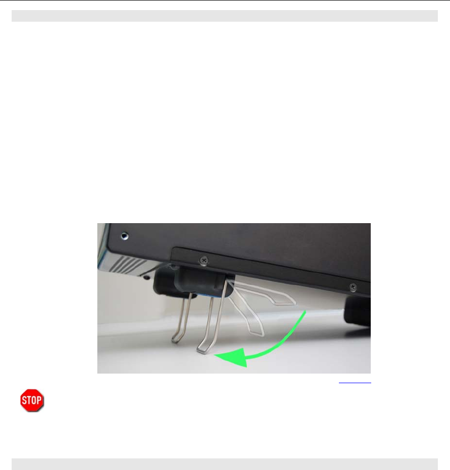
For your convenience you might raise the PT8000 and the HN-8000 by unfolding and locking into
position the front stand under the cabinet as shown on the picture.
Allways handle the PT-8000 with care – consider the weight of more than 50 lbs, please!
3.4 Antenna Considerations
Standing wave ratio (SWR) may increase significantly when using an antenna outside of the specific
frequency range for which it is tuned. The final power amplifier will operate at peak performance only
when its load is resistive – i.e. the SWR is close to 1.0. Therefore the PT-8000 is equipped with an
automatic antenna tuner (ATU) which does not actually tune the antenna. The ATU instead matches the
feedline to the final amplifiers so they always “see” and SWR of 1.0. The ATU has its limits – tuning
mismatches with SWR greater than 2.0 become difficult and will exceed the capabilities of the ATU.
Using a tuned or resonant antenna with 50 Ohm impedance at the feedpoint for the specific frequencies
is highly recommended. The purpose of the ATU is to ensure that a resonant antenna can be used at the
limits of the band selected with optimum performance of both PT-8000 and antenna system. Never try to
hook up a symmetrical open feeder line (balanced, twin-lead, ladder line etc,) directly to the PT-8000.
Instead use 50 ohm coaxial feeders only. The connectors supplied on the PT8000 are all Type N.
With the ATU it is acceptable to use a broadband antenna system like a log periodic or T2FD system
which trade wide bandwidth for an SWR ranging as high as 2.0.
Picture 1
PT-8000
A
·
B
·
C User Manual C–3
4 C
ONNECTORS
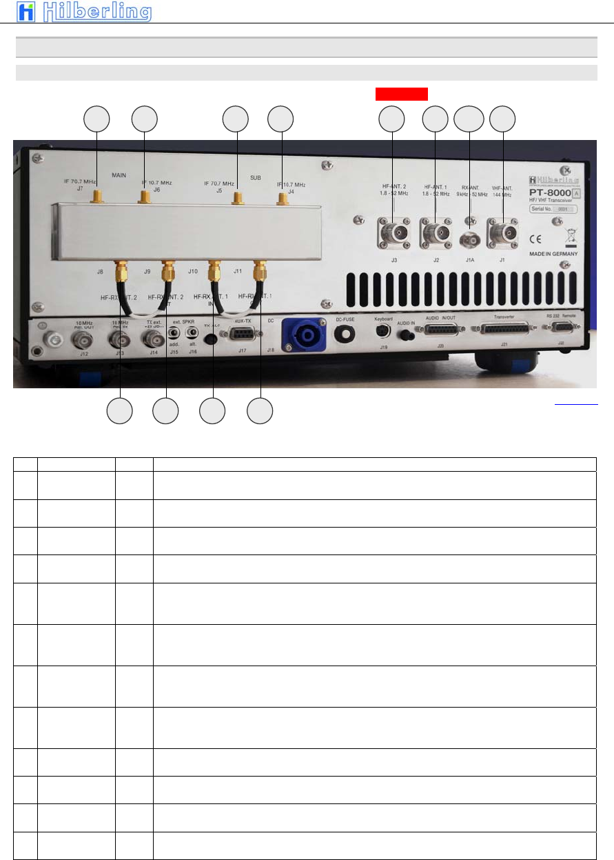
4.1 Rear Panel
A variety of jacks are accessible at the rear panel. Please unfold Picture 1 - pointing out all connections.
HF/VHF-Connection Sockets J1 ... J11
No NAME Type Description
J1 VHF-ANT
110 … 170 MHz
N-Type Connect a VHF-Antenna for 110 to 170 MHz (RX) and 144 to 148 MHz (TX)
J1A RX-ANT
9 kHz ... 54 MHz
BNC Connect a VLF/HF/VHF-antenna for receive only from 9 kHz … 52 MHz / 54 MHz (USA). For DUPLEX
mode the input may stay open during transmission.
J2 HF-ANT.1
1.8 ... 52 MHz
N-Type Connect VLF/HF/VHF-antenna #1 frequency coverage 9kHz ... 52 MHz / 54 MHz (USA)
J3 HF-ANT.2
1,8 ... 52 MHz
N-Type Connect VLF/HF/VHF-antenna #1 frequency coverage 9kHz ... 52 MHz / 54 MHz (USA)
J4
IF 10.7 MHz
SUB
SMA
Output 1st IF 70.7 MHz of SUB-RX. The output is tapped after the 1st mixer and the IF-amplifier HV20-200
– thus being broadband when preselector is disengaged
J5
IF 70.7MHz
SUB
SMA Output 2nd IF 10.7 MHz of SUB-RX. The output is tapped after the 2nd mixer and IF-notch and noise
blanker circuit. No AGC and no 10.7MHz xtal filter at that point. Thus bandwidths are determined by roofing
filter.
J6
IF 10,7 MHz
MAIN
SMA
Output 1st IF 70.7 MHz of MAIN-RX. The output is tapped after the 1st mixer and the IF-amplifier HV20-200
– thus being broadband when preselector is disengaged
J7 IF 70.7MHz
MAIN
SMA Output 2nd IF 10.7 MHz of MAIN-RX. The output is tapped after the 2nd mixer and IF-notch and noise
blanker circuit. No AGC and no 10.7MHz xtal filter at that point. Thus bandwidths are determined by roofing
filter.
J8 HF-RX ANT. 2
IN
SMA J6/J7 disconnects RX (MAIN/SUB) from HF-ANT.2 – J6 is either connected to J7 or to output of external
equipment (QRM-eliminator, ANT-switch panel etc.)
J9 HF-RX ANT. 2
OUT
SMA HF-ANT.2 (in RX-mode) either connected to J6 or to input of external equipment (QRM-eliminator, ANT-
switch panel etc.)
J10 HF-RX ANT. 1
IN
SMA J8/J9 disconnects RX (MAIN/SUB) from HF-ANT.1 – J8 is either connected to J9 or to output of external
equipment (QRM-eliminator, ANT-switch panel etc.)
J11 HF-RX ANT. 1
OUT
SMA HF-ANT.2 (in RX-mode) either connected to J8 or to input of external equipment (QRM-eliminator, ANT-
switch panel etc.)
Table 3
J1J2J3J5 J6 J4 J7
Picture 2
J11 J10
J9 J8
J1A
C–4 Part C Installation And Operation
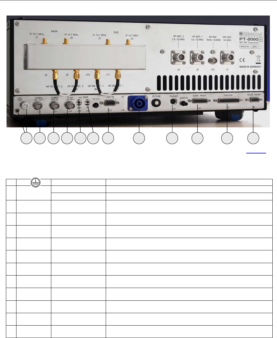
Connection Sockets J12 … J22
No NAME Type Description
Banana Plug 4mm Grounding wire – must be connected toHN-8000 power supply E
M6 Grounding stud – must be connected to HN-8000 power supply and to station ground
J12 10 MHz Ref.
OUT
BNC Output for an external 10 MHz reference signal (clock) for synchronization of PT-8000 to
other equipment
J13 10 MHz Ref.
IN
BNC Input of internal/external 10MHz reference clock (internal: derived from 20 MHz system
clock with 0.05 ppm) for synchronization of external equipment to PT-8000
J14 TX ext.
+20 dBm
BNC TX external output (1.8…148 MHz). Level is +20 dBm to drive transverter or external
power amplifier
J15 ext. SPKR
add.
EIA-453 / IEC 60603-11
Phone Plug / TRS 3.5mm
Additional external speaker output. Use to connect the speaker at HN-8000 in addition to
built in speaker
J16 ext. SPKR
alt.
EIA-453 / IEC 60603-11
Phone Plug / TRS 3.5mm
Alternate external speaker output. Use to connect an alternate speaker to the built in
system
J17 AUX-TX
(PTT/ALC)
DE-9
(D-Sub 9pol)
J18 DC
IN
CliffCon
4-pol
Power connector for interconnection cable to HN-8000 power supply
J19 Keyboard
mini-DIN
PS/2 Connector
To be implanted later.
J20 AUDIO
IN/OUT
DA-15
(D-Sub 15pol)
To be implanted later.
J21 Transverter
DB-25
(D-Sub 25pol)
To be implanted later.
J22 Remote
RS 232
DE-9
(D-Sub 9pol)
Interface to update firmware of PT-8000
Table 4
E
J12 J13 J14 J16 J17 J18 J19 J20 J21 J22 J15
Picture 3
PT-8000
A
·
B
·
C User Manual C–5
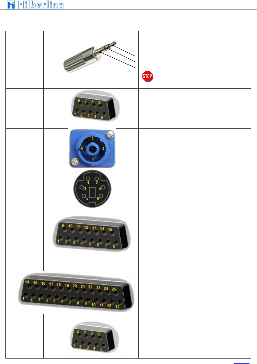
Wiring of J15 … J22
Nr. Name Typ Function And Outline
J15
J16
ext. SPKR
add.
ext. SPKR
alt.
Connect an additional (PT-8000 speaker will stay ON) or an
alternate speaker (PT-8000 speaker will be OFF)
1 Tip + audio output (4,5 W max)
2 Ring + audio output
3 Sleeve GND
Caution: Using mono type plugs will shorten the
audio output and may damage the
transceiver
J17 AUX-TX
(PTT/ALC)
To be implanted later.
J18 DC
IN
PT-8000A PT-8000B PT-8000C
1 (2-) 13,8 VDC 13,8 VDC 13,8 VDC
2 (1+) 50 VDC PA <Not Connected> <Not Connected>
3 (1-) GND GND GND
4 (2+) <Not Connected> 100 VDC PA <Not Connected>
J19 Keyboard
To be implanted later.
J20 AUDIO
IN/OUT
To be implanted later.
J21 Transverter
To be implanted later.
J22 Remote
RS 232
1 <Not Connected> 6 <Not Connected>
2 RS232 TX 7 RS232 RTS
3 RS232 RX 8 <Not Connected>
4 RS232 DTR 9 <Not Connected>
5 GND
Table 5
C–6 Part C Installation And Operation
Miscellaneous
DC-Fuse 13.8 V DC circuit breaker for final PA rated 13,8 V / 25 Amp. for PT-8000C and
50 V / 15 Amp. or 100 V / 15 Amp. for PT-8000A/B
TX-ALC Sensitivity of ALC input (J17, pin 6) from external PA to reduce TX power out.
AUDIO IN Sensitivity of Audio data input (J20, pin 2) – rated 0 dBm.
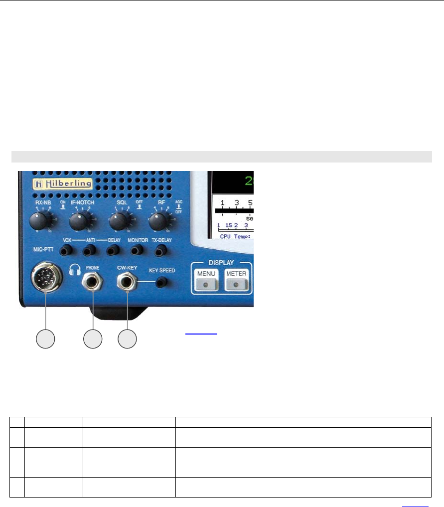
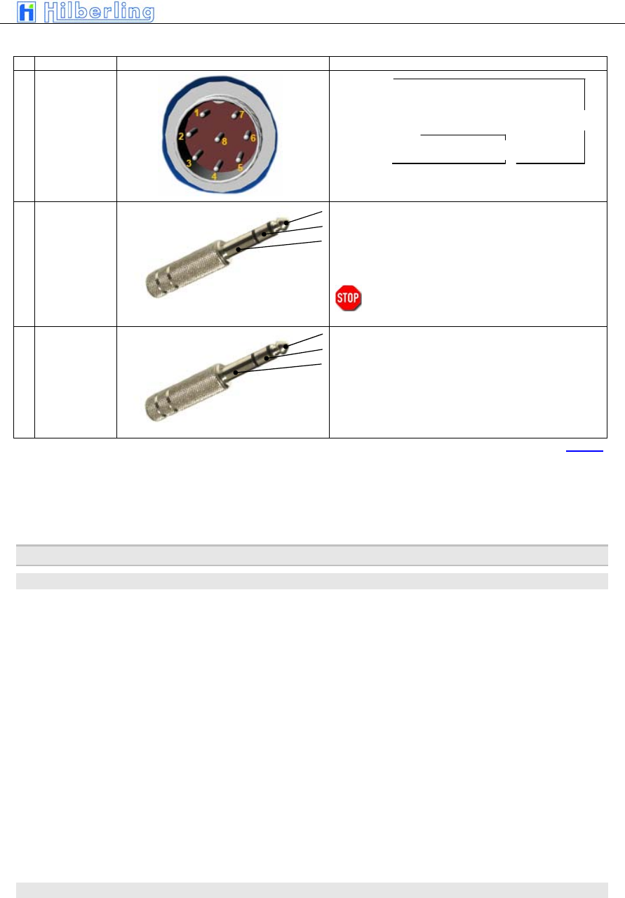
4.2 Connectors At Front Panel
Connection Sockets 1 ... 3
Nr. Name Typ Beschreibung
1 MIC-PTT
Microphone Socket
8-pol
Microphone connector for Hilberling T9 and Data input 0 dBm
2 PHONE
EIA-453 / IEC 60603-11
TRS 6.3 mm
Headphones low impedance (8 Ω). When plugged in the speaker(s) will be cut off.
NOTE: pushing the volume controls for MAIN and SUB will switch on the speaker(s)
momentarily
3 CW-KEY
EIA-453 / IEC 60603-11
TRS 6.3 mm
Keyer for CW
Table 6
1 2 3
Picture 4
PT-8000
A
·
B
·
C User Manual C–7
Wiring
Nr. Name Typ Funktion und Anschlussbelegung
1 MIC-PTT
0 dBm
1 MIC-Audio
2 PTT
3 RX-MAIN Audio (headset)
4 0 dBm IN
5 MIC IN +DC
6 RX-SUB Audio (headset))
7 MIC-GND
8 PTT-GND
2 PHONE
1 Tip + Audio OUT
2 Ring + Audio OUT
3 Sleeve GND
NOTE: Audio for PHONE is derived from audio preamplifier
especially designed for phone operations.
Caution: Using mono type plugs will shorten the
audio output and may damage the
transceiver
3 CW-KEY
1 Tip DOT CW-Key
2 Ring DASH <Not Connected>
3 Sleeve GND GND
STATUS: Keyer ON Keyer OFF
Table 7
5 P
OWER
S
UPPLY
5.1 General
Each model PT-8000 A/B is equipped with its appropriate power supply all named HN-8000. The only
difference in appearance for the PT-8000A-model and the PT-8000B-model is the final amplifier DC
input power instrument at the front panel.
The HN-8000 is a switching power supply with industry standard. It complies with special regulations in
some countries regarding power factor compensation (PFC).
Operating voltages from the mains can be in the range of 90 VAC to 260 VAC without any degradation in
output power. Only the efficiency will vary slightly. The HN-8000 operating temperature is controlled by
up to 4 fans (PT-8000B). The HN-8000 accompanied with the PT-8000A and PT-8000B delivers 50 VDC
@ 15Amps and 100 VDC @15 A for the high power B-model.
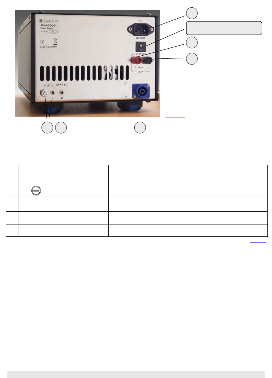
5.2 Rear Panel
Electret Mic
Dynamic Mic
C–8 Part C Installation And Operation
Connection Sockets J1 ... J5
Miscellaneous
AC-FUSE Circuit breaker for AC mains at rear panel plug J5 rated 16 A @ 90 … 270 V AC
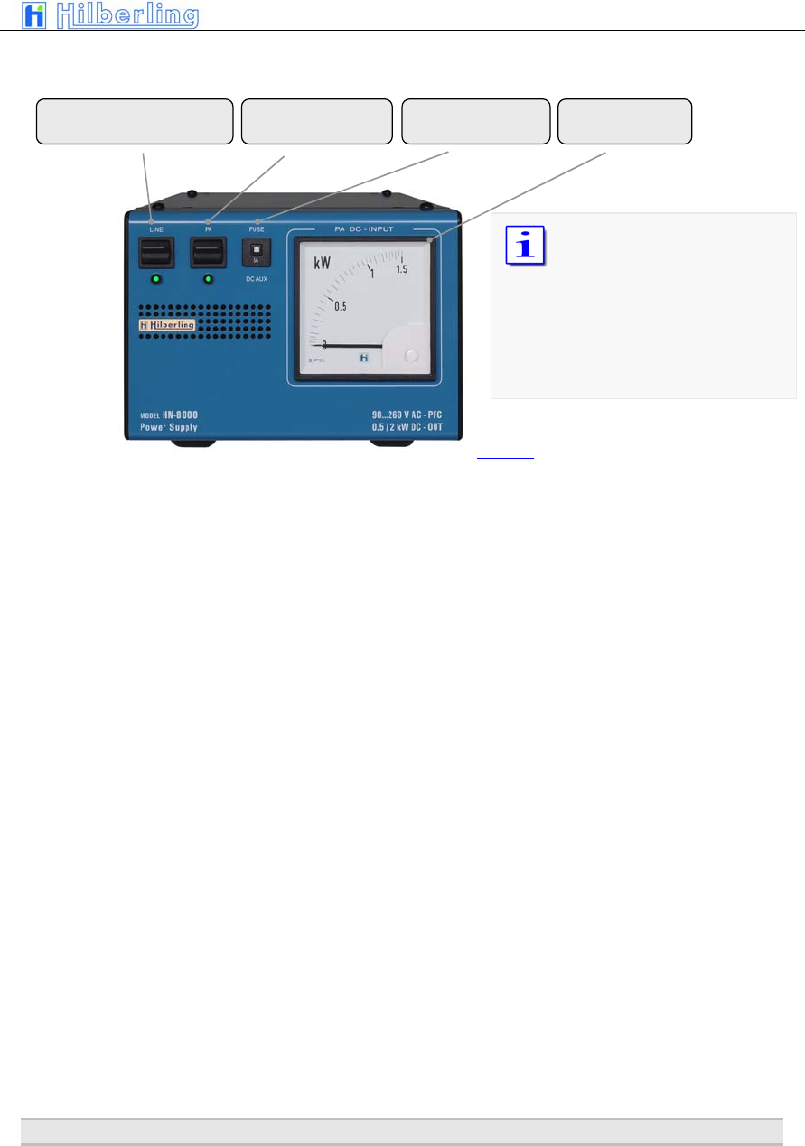
5.3 Front Panel
Nr. Name Type Description
J1 AC IEC-60320-C13 Input main power 90 – 270V AC
J2/3 13,8 V DC Banana Plug 4 mm + Clamp Auxiliary output 13.8V DC
Banana Plug 4 mm Grounding wire – must be connected to PT-8000 transceiver
E
M6 Grounding stud – must be connected to PT-8000 transceiver and to station ground.
J4 SPKR 8 Ω EIA-453 / IEC 60603-11
Phonostecker / TRS 3.5 mm Input for built in speaker from PT-8000 J15 or J16
J5 DC CliffCon
4-pol
Power connector for interconnection cable to PT-8000 J18.
Table 8
E J4 J5
J1
J2
J3
Circuit breaker for AC
Picture 5
PT-8000
A
·
B
·
C User Manual C–9
Miscellaneous
DC FUSE Circuit breaker for DC AUX at rear panel banana plugs J2/J3 rated 5 A @ 13.8 V DC
6 A
CCESSORIES
ON/OFF for DC Low Power
DC AUX
ON/OFF
DC Power Amplifier
DC-Fuse
AUX Power Meter
The power meter indicates
the DC input power of the
final power amplifier – hence
computation of efficiency
could be easily done by
comparing RF-power out as
indicated on PT-8000 display
and DC-input shown here.
Picture 6
C–10 Part C Installation And Operation
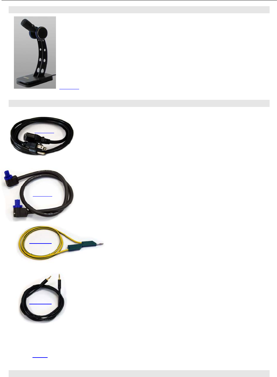
6.1 Microphone Hilberling T9
Best suited for all voice operations is the Hilberling T9 microphone especially
designed for the PT-8000.
Isolated from any mechanical vibrations and designed to be used from more
closer as well as from greater distance it will always guarantee high fidelity
audio and if desired an extra punch to the signal.
Impedance is 600 Ω @ 1kHz. The acoustic characteristic is kidney-shaped.
6.2 Wiring/Cables
AC-line voltage cable for HN-8000; length appr. 1,70 m
DC-cable HN-8000PT-8000; length appr. 1,10 m
Ground cable HN-8000PT-8000; length appr. 1,50 m
Speaker cable HN-8000PT-8000; length appr. 1,50 m
BILD fehlt RS232-data cable to connect a PC; length appr. 1,80 m
6.3 Pull Out Instruction
Picture 7
Picture 8
Picture 10
Picture 11
Bild 12
Picture 9
PT-8000
A
·
B
·
C User Manual C–11
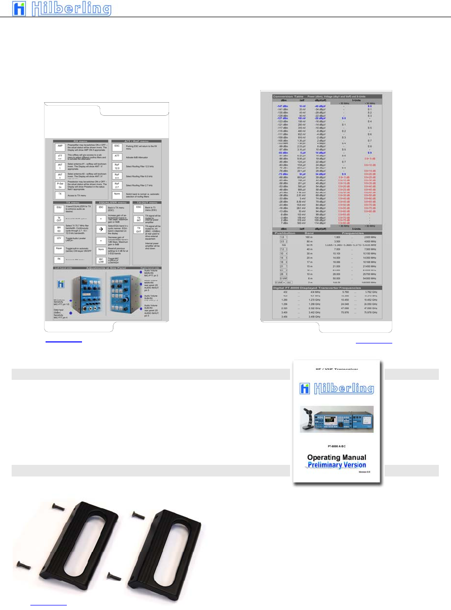
Just pull out the two quick reference cards to obtain useful information – a quick operating reference and
A conversion table dBm – dBµV – S-units.
Upper left hand card Lower right hand card
6.4 Operating Manual
This Operating Manual Version 1.0
6.5 Handles
Two handles may attached to the PT-8000 easily
using the mounting material provided.
Picture 13 Picture 14
Picture 15

C–12 Part C Installation And Operation
–– This page is intentionally blank ––
Part C Installation And Operation
PT-8000
A
·
B
·
C User Manual C–13
7
I
NSTALLATION
A
ND
C
ONNECTIONS
Prior to any operation of the PT-8000 read this Operation Manual carefully.
The PT-8000 will be delivered with the following presettings:
• The preselector is aligned and all data’s are stored in RX-CPU memory which is buffered through
a NiCd battery
• The transmitter is limited to the frequencies in compliance with FCC regulations
The default values for the operation variables are (these default values are set after a hard reset as well)
TBD
Prior applying main power to the power supply HN-8000 verify:
Rear panel
• Antenna(s) are connected properly
• Grounding stud is connected to station ground
• Grounding wire is connected to both PT-8000 and HN-8000
• DC-cable is connected to both HN-8000 and PT-8000
For initial operation we recommend not to connect external amplifier, transverter or devices for remote
operation.
Front panel
• Microphone attached
These controls ahould be set fully counter clockwise:
• Volume controls MAIN/SUB
• TX-RWR
• MIC-GAIN
• PROC
Power ON sequence PT-8000
• Turn ON both LINE and PA on HN-8000
• Turn ON POWER at PT-8000
The POWER switch at the PT-8000 does not switch the voltage from the PA
power supply. This is done by the PA switch at the HN-8000 only.
It is up to the operator to switch PA OFF during reception only.
8 F
RONT PANEL
C
ONTROLS
,
D
ISPLAY AND THEIR
F
UNCTION
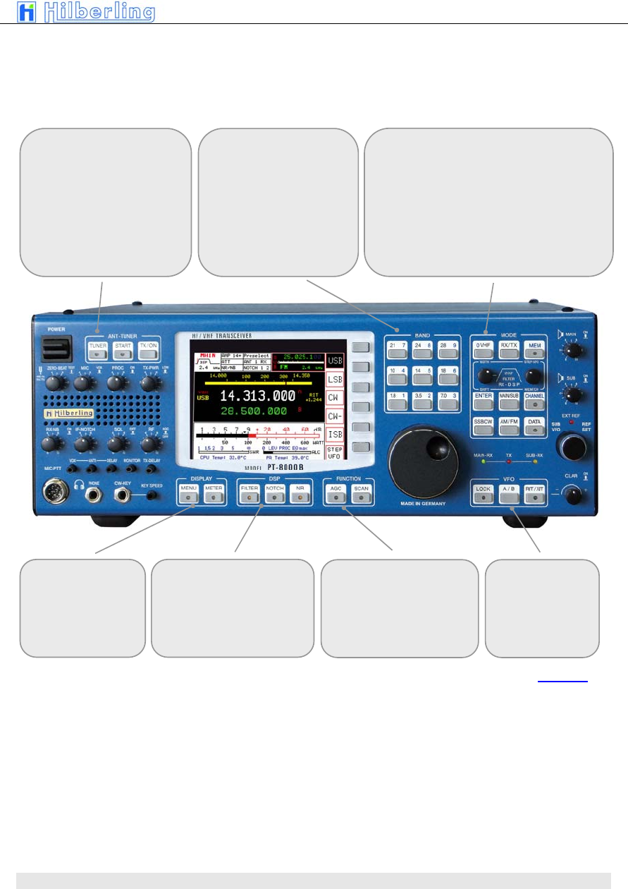
8.1 Front Panel Controls
Volume MAIN- and SUB-RX
Speaker ONOFF
C–14 Part C Installation And Operation
Function NAME Description
Power ON/OFF POWER Main power is supplied through this switch.
Before turning ON verify audio volume settings for MAIN and SUB-RX are turned
counter-clockwise. After switching to ON:
LED MAIN-RX will illuminate
an intermitted beep will indicate that the initialization is in progress
the display will stay dark completed (approximately 5 seconds) until the initialization process is
completed
Display ÷ The displayrepresents the primary means to control through soft switches and to show all relevant
data for RX and TX operations.
Volume MAIN-RX : MAIN Volume for audio MAIN-Receiver. The RX is always turned on – audio is always present
regardless of RX-status (active or in the background – see below). Pushing toggles the speaker
ON and OFF (depending on NORMAL or SPLIT Audio Mode – see page C42)
Volume SUB-RX : SUB Volume for audio SUB-Receiver. The RX is always turned on – audio is always present regardless
of RX-status (active or in the background – see below). Pushing toggles the speaker ON and OFF
(depending on NORMAL or SPLIT Audio Mode – see page C42)
Primary
Tuning Knob
÷ Tuning of VFO A/B of “active” RX. MAIN- and SUB-RX are always receiving. The term “active” is
used in the following context: “Active” means which RX (MAIN or SUB) is controlled by the main
Display (through soft switches) and which RX-Data is completely shown in the display.
Default setting: MAIN RX is the active RX
SUB VFO Tuning of VFO A/B of RX, which is not the „active“ one i.e. working in the Background (see
above). Default setting: SUB-RX is in the background
Secondary
Tuning Knob
REF-SET When operating the PT-8000 with an external reference (10MHz-clock) this control will allow
aligning the timing in small increments. This mode is indicated by the LED „EXT-REF“
Table 9
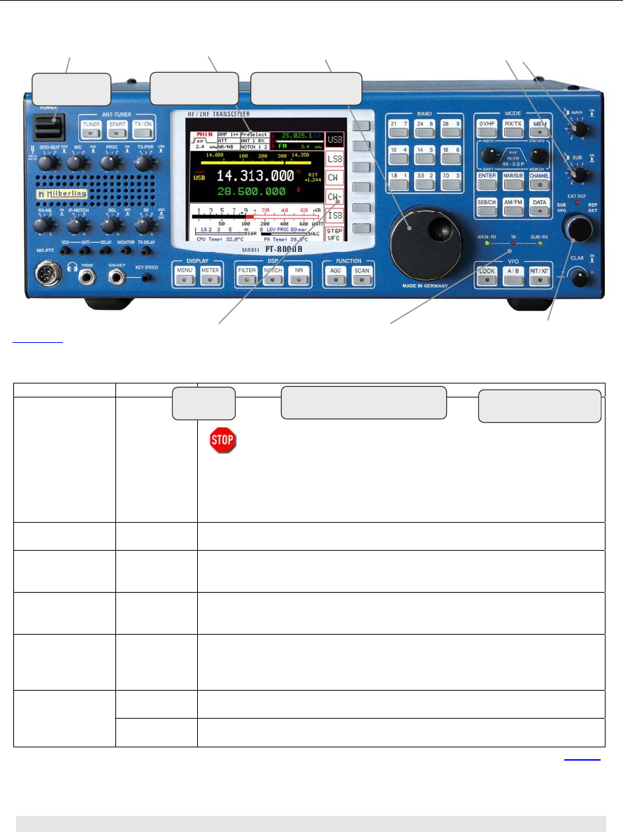
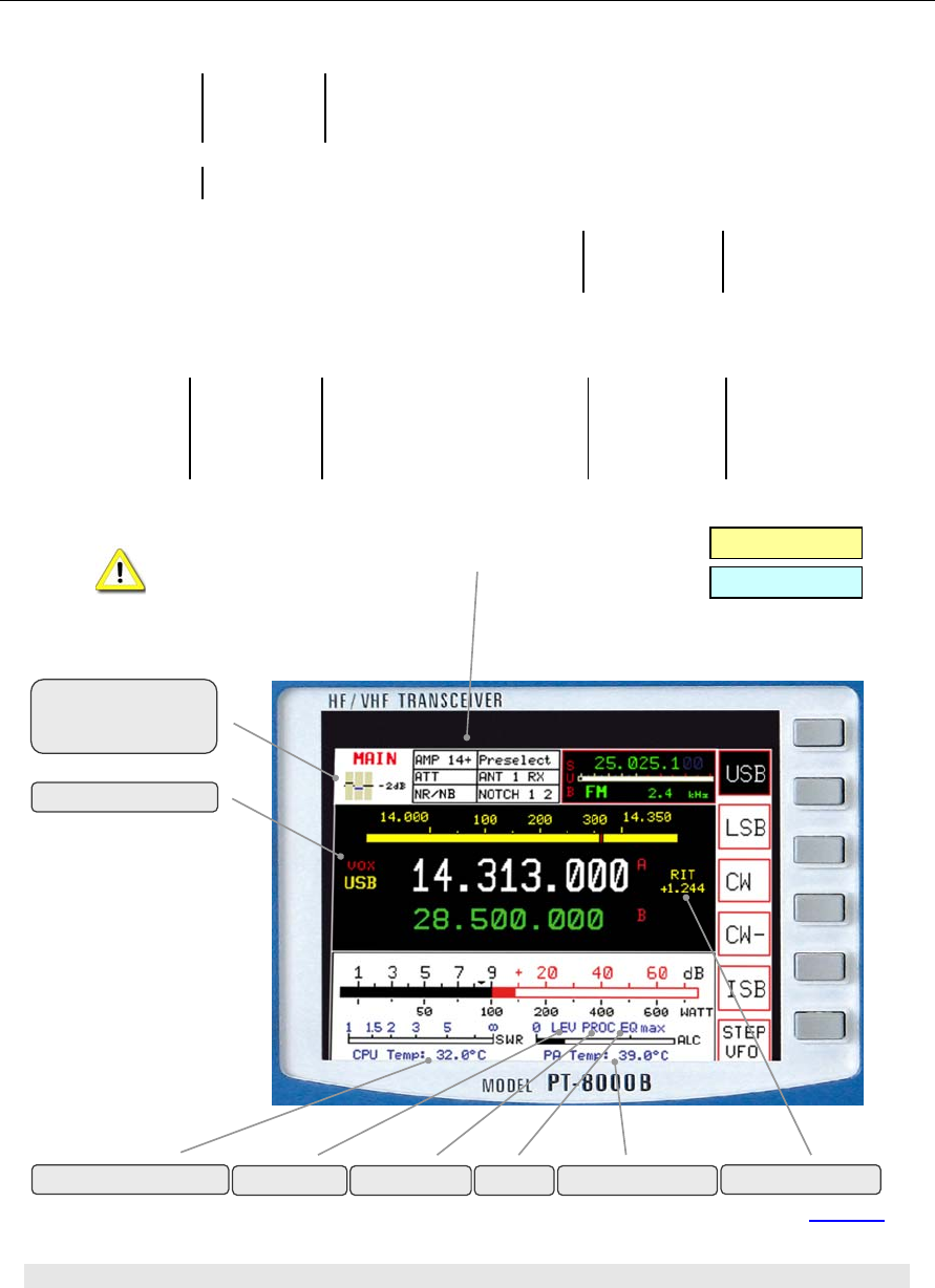
8.2 Display
The display of the PT-8000 shows relevant data of MAIN- and SUB-RX and the TX.
POWER
ONOFF TFT-Display Main Tuning
Tuning 2nd RX
LED for status
MAIN-RX / TX / SUB-RX
Softkeys
Picture 16
PT-8000
A
·
B
·
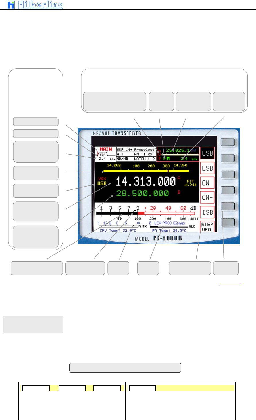
C User Manual C–15
• All settings fort the active RX
• Main settings for the non-active resp. for the RX
in the background
• General Data for RX and TX
• Functions to be activated by the adjacent keys
(Soft keys)
The keys right next to the functions depicted on the display are the so-called
„Soft keys“. They activate/select the functions named on the display. These
functions will vary with the menu selected through pressing different controls
on the front panel.
RX in background (here: SUB) with
limited access through controls
Selected VFO for RX in background
RX
which is selected as
active
Note: Each VFO
setting includes
bandwidth and mode
SWR
Squelch Marker
b
S-Meter
Power Output Soft keys Function of Key
Selected VFO
Frequency + ID
(A or B)
Bandwidth 2nd IF
Filter allocated to
selected VFO
RX- ID (MAIN/SUB)
standby VFO
Frequency + ID
(A or B)
Selected VFO
allocated Mode
Mode Frequency Bandwidth of
2nd IF filters
DSP Filter Marker
RX ID
(MAIN/SUB
TRansVerter/CONVerter)
Band Information
or Linear Scale
Picture 17
ALC
Soft keys
and
Soft key menu
AMP AMP 7+ AMP 14+ . Preselect
Statusfield – display options
C–16 Part C Installation And Operation
A blank status field indicates that the corresponding
function is OFF (ATT; AMP; Presel; NB/NR; Notch etc.)
8.3 Clustered Front Panel Controls
TX 3-Band-Equalizer
if EQ-menu is selected
VOX ON
HF Mode
VHF Mode
DSP-
noise reduction
ON
RX-
noise blanking
ON
NR + NB
ON
DSP-
Notchfilter
ON
IF-
Notchfilter
ON
DSP + IF
Notchfilter
ON
ON
for f ≥ 1.8 MHz
for f >7 MHz for f >14 MHz
ON
available between f = 1.8 ...30 MHz
Preamplifier
Attenuator
Preselector
Selected antenne
Picture 18
RIT/XIT ON
LEVeler ON PROC ON PA TemperatureEQ ON
MAIN-CPU Temperature
PT-8000
A
·
B
·
C User Manual C–17
Various controls are clustered – indicated through
surrounding white boxes painted on the panel
8.4 Controls With Integrated Push-Button Function And Controls For Adjustments
BAND
– Select HF-Ham Band
Note: 60m not present
– Numerical input of
frequencies
ANT-TUNER and MOX
– Activation of Tuner
– Start tuning cycle
– Manual TX/ON - MOX
DISPLAY
– Select special MENU
DSP
Activation of
– Digital Filter
– Automatic Notch Filter
– Automatic Noise Reduction (NR)
FUNCTION
– Automatic Gain Control (AGC)
– Activate Scan Function
V
FO
– Lock VFO
– toggle VFO A/B
– Activation of RIT/XIT
MODE
– Select VHF-Band
„0“- Key for numerical Input
– Select basic RX/TX- menu
– Storage of frequencies
– Filter selection (Xtal and DSP)
– STEP-VFO
– Activate numerical Input
– Selct RX (MAIN or SUB)
– Recall channels and Channel storage management
– Select mode (SSB/CW/AM/FM/DATA)
Picture 19
C–18 Part C Installation And Operation
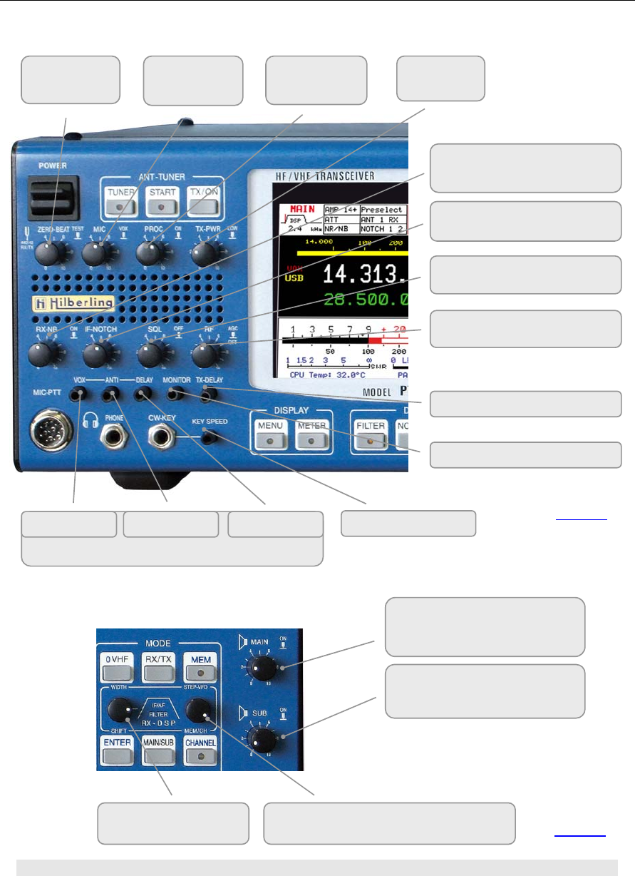
8.5 Side Panel Controls
NOISE BLANKER
Activate
IF-NOTCH FILTER
Activate
SQUELCH threshold and
Override
RF-GAIN
AGC Off
Volume MONITOR
TX-Delay
Adjustments / settings for VOX
Sensitivity ANTI TRIP DELAY
ZERO BEAT
Activate
MIC-GAIN
VOX
PROCESSOR
Activate
TX-POWER
High/Low
CW Key Speed
Volume MAIN RX
Push function switches speaker
according to AUDIO Normal/Split
Volume SUB RX
Push function switches speaker
accordin
g
to AUDIO Normal/S
p
lit
See also AUDIO Menu on page C42
Filter WIDTH/SHIFT
toggle
STEP VFO MEM/CH
select digit select channel
Picture 20
Picture 21
PT-8000
A
·
B
·
C User Manual C–19
Left hand side
P2 coarse adjustment of microphone sensitivity
front panel 1: MIC-PTT pin 1/5
P6 adjustment of data input (0 dBm) sensitivity
front panel 1: MIC-PTT pin 4
The adjustment of sensitivity from MIC and
Data Input are twofold: coarse adjustment is
Done at an early stage right after the input
transformers. MIC gain settings from the
front panel controls amplifier and gain leveler
circuit on the TX board.
Right hand side
P1 coarse adjustment of audio volume MAIN-RX
front panel 1: MIC-PTT pin 3
P3 coarse adjustment of audio volume MAIN-RX
rear panel J20: AUDIO IN/OUT pin 5
P4 coarse adjustment of audio volume SUB-RX
front panel 1: MIC-PTT pin 3
P5 coarse adjustment of audio volume SUB-RX
rear panel J20: AUDIO IN/OUT pin 20
Use an appropriate tool to adjust the controls to prevent any damage to the
variable resistors
8.6 Keys With LED And LEDs
Picture 22
Picture 23
C–20 Part C Installation And Operation
Because the operator should be aware of some major functions whether they
are active or deactivated certain push buttons incorporate a LED:
MEM MENU
CHANNEL METER
DATA FILTER
LOCK NOTCH
RIT/XIT NR
TUNE AGC
START SCAN
The PT-8000 incorporates a transmitter and two independent receivers (MAIN
and SUB). Both receivers are permanently operating. Even if a receiver is „in
the background“ i.e. not fully accessible through all main controls the receiver
is operating with its last settings when it has been the „active“ one.
One transmitter and two receivers are operated in three main modes:
• MAIN-RX is active and SUB is working in the
background (green MAIN-RX LED is on)
or
• SUB-RX is active and MAIN is working in the
background (yellow SUB-RX LED is on)
• TX is operating (red TX-LED is on).
Note: The MAIN RX VFOs will always determine the transmit frequencies
The red LED EXT REF will be on when the PT-8000 20 MHz system clock is
no longer the internal one. An external 10MHz signal is representing the
frequency reference when this LED is on.
9 MAIN-
A
ND
SUB-RX
O
PERATIONS
Picture 24
MAIN RX
and
SUB RX
PT-8000
A
·
B
·
C User Manual C–21
The PT-8000 incorporates a transmitter and two independent receivers (MAIN
and SUB). Both receivers are permanently operating. Even if a receiver is „in
the background“ i.e. not fully accessible through all main controls the receiver
is operating with its last settings when it has been the „active“ one.
Two controls are doubled, hence for these functions MAIN-/SUB-RX are
always accessible regardless of their status:
1. The selected VFO of the RX working in the background is always
accessible through SUB VFO.
2. The volume of MAIN- and SUB-RX are permanently adjustable through
the respective controls MAIN and SUB.
3. Both knobs have a “push” function: Depending on the AUDIO setting
NORMAL/SPLIT the audio from MAIN and SUB are allocated to the
speakers and are turned ON and OFF (see page C42)
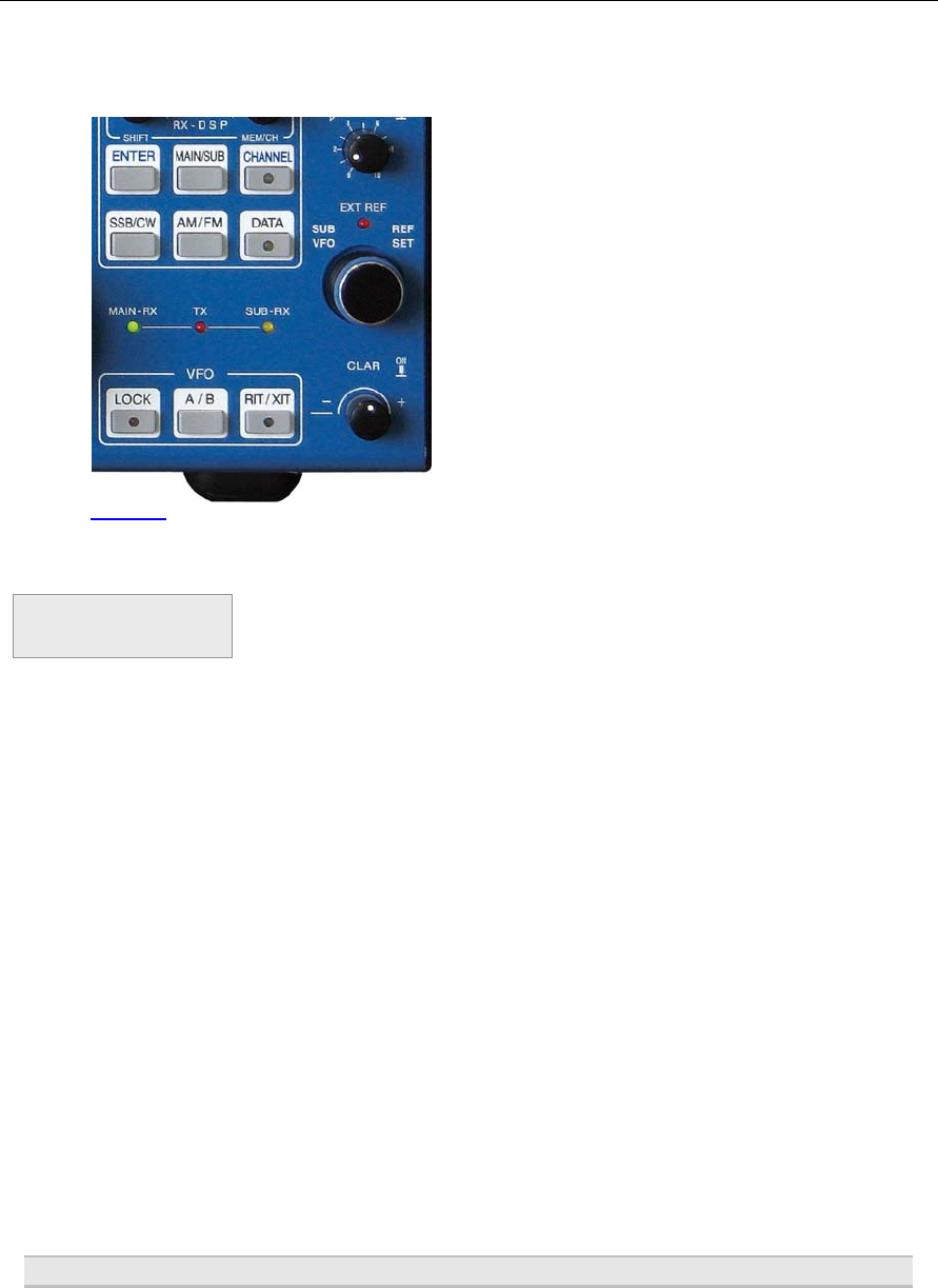
The push button MAIN/SUB (see picture 27 page C11) toggles between the
two RX changing their status „active“ or „background“. During initial start up
the PT-8000´s MAIN-RX is the active one.
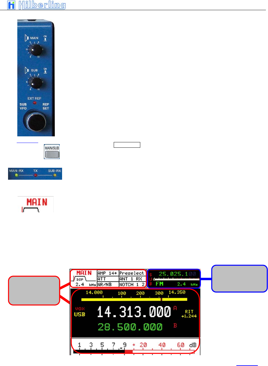
• LED MAIN-RX and LED SUB-RX indicate which
RX is the active one
• The Display shows in the upper left corner MAIN
or SUB
• Frequency, mode, filter bandwidths are
displayed for MAIN and SUB respectively
Activation of noise blanker, DSP, DSP-notch and the squelch marker are
displayed for the active RX exclusively.
Picture 25
Settings from
RX which is in
the active one
Settings from RX
which is in the
back
g
round
Picture 26

C–22 Part C Installation And Operation
When toggling between MAIN- and SUB-RX the actual settings of the controls
used at last are not transferred to the new active RX – instead the former
settings of this RX are the actual one – until they are overwritten by the
respective control.
The squelch threshold set to the RX working in the background will stay the
actual one when this RX becomes the active – until one touches the squelch
control to set the threshold to a new setting.
The large S-meter is always allocated to the active RX. The smaller S-meter
is indicating the fieldstrenght of the RX working in the background.
Pressing PTT when SUB-RX is the active one will toggle MAIN- and SUB-RX
instantaneously. As mentioned before only the MAIN-RX can operate with the
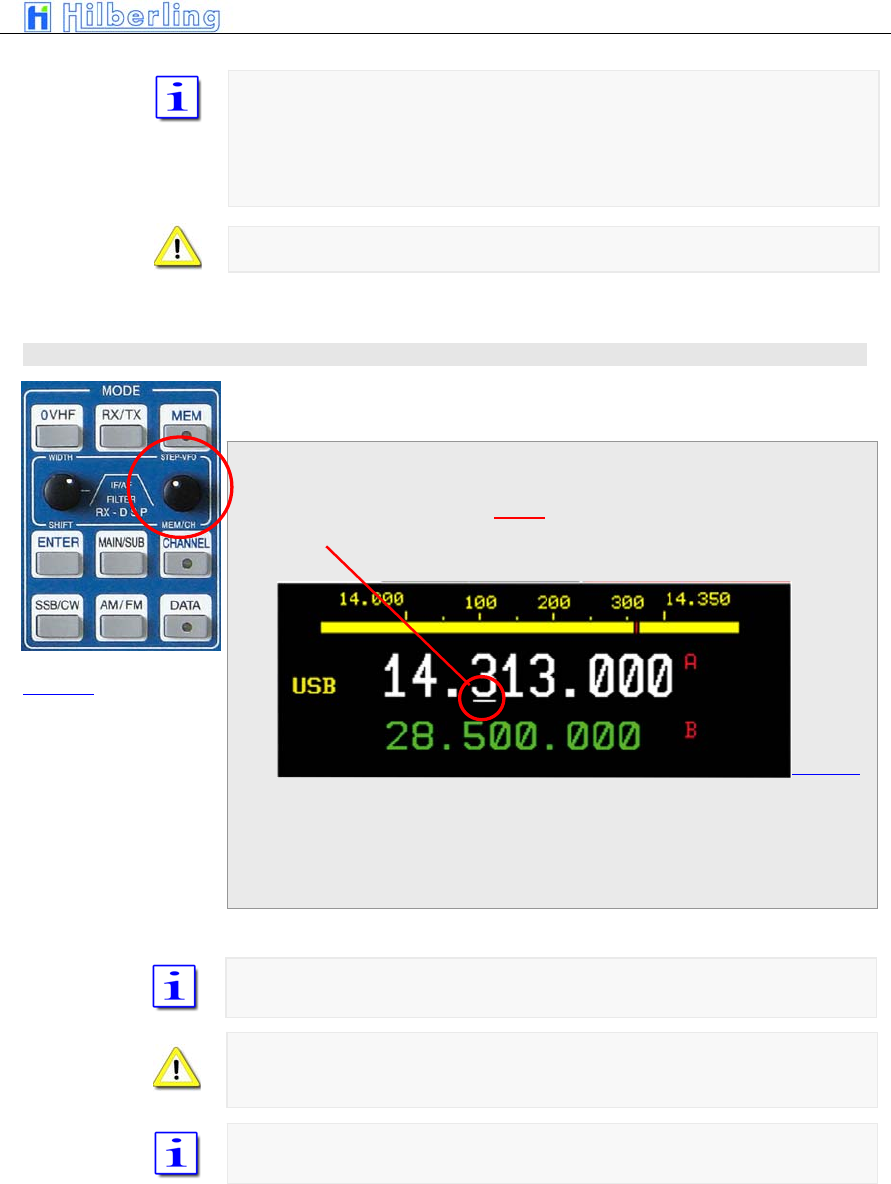
TX as a transceiver.
When transmitting SUB-RX may be used to monitor own RF-signal. Receiving
with SUB-RX on a separate antenna is limited however: Excessive field
strength may trip the protection circuits. Receiving at frequencies adjacent to
the tranmitting frequency may be limited even by the superior dynamic
characteristics of the PT-8000 receivers - which are of course finite.
Example
PT-8000
A
·
B
·
C User Manual C–23
SSB/CW menu
10 M
ODES
O
F
O
PERATION
(MODE)
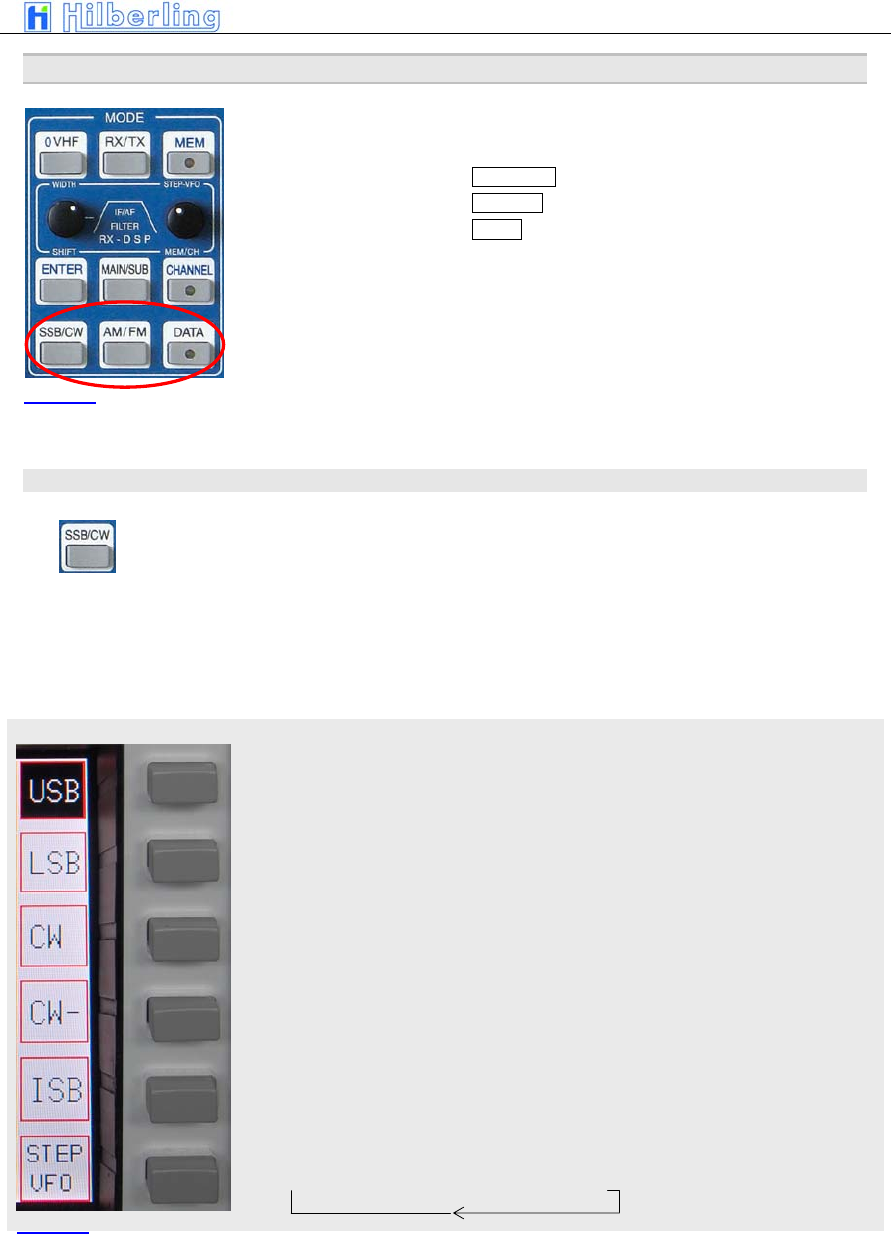
In order to select different modes pushbuttons are available (see Figure ….)
in the clustered area MODES:
• SSB / CW (where ISB is selectable)
• AM / FM
• DATA
When SSB/CW or AM/FM is pressed the last selected mode (SSB/CW or
AM/FM) is memorized and reactivated. The display shows the activated mode
inverse.
10.1 SSB / CW (Single Side Band / Continuous Wave)
Pressing SSB/CW will call up the SSB/CW soft key menu:
10.1.1 SSB (Single Side Band)
Upper Side Band
Lower Side Band
Continuous Wave normal mode (CW-pitch in USB)
Continuous Wave inverse mode (CW-pitch in LSB)
Independent Side Band – the ISB menus will appear (see below)
Cyclic change of frequency tuning steps:
→ 1 Hz → 10 Hz → 100 Hz → 1 kHz →
Picture 27
Picture 28
C–24 Part C Installation And Operation
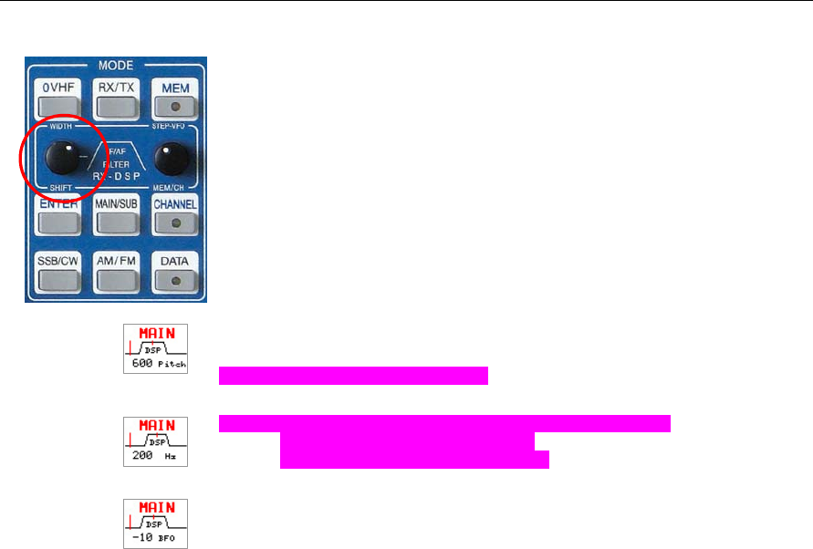
10.1.2 CW (Continuous Wave)
When CW or CW- is selected pushing the WIDTH/SHIFT control will cycle
between Pitch – Width – BFO. Turn WIDTH/SHIFT to control:
Pitch - will change the beat frequency of the received signal. At the same
time the center frequency of the DSP-filter is shifted accordingly.
Range 400 … 1000 in 50 increments
Width – will change the DSP-filter width with following values:
50 / 100 / 200 / 400 / 500 / 600 Hz
When DSP is disabled: 500 Hz fixed.
BFO – will change the beat frequency of the CW signal from –250 Hz to
+250 Hz in 10 Hz increments without changing the center frequency of the
DSP filter.
PT-8000
A
·
B
·
C User Manual C–25
ISB Menü
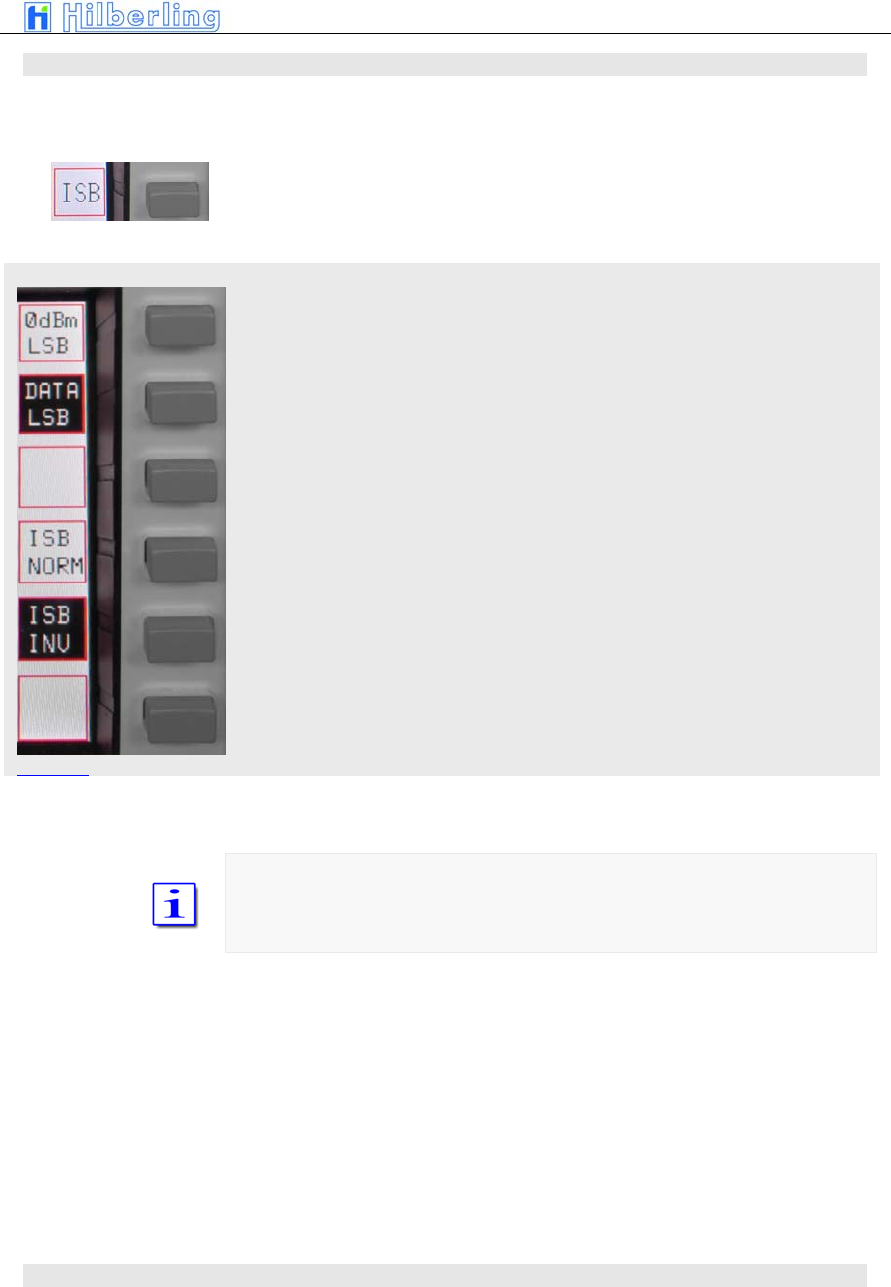
10.2 ISB (Independent Side Band)
During independent sideband operations MAIN- and SUB-RX are tuned to the
same frequency but on different sidebands. Both sidebands are transmitted
and modulated independently.
Pressing ISB will call up the ISB menu:
„0dBm“ input (connected to MIC jack) will be transmitted on USB/LSB –
depending on status of ISB NORM/INV
DATA input (connected to J17 on rear panel) will be transmitted on USB/LSB
– depending on status of ISB NORM/INV
ISB normal - 0dBm or DATA input are transmitted on USB. Voice will be on
LSB
ISB inverse - 0dBm or DATA input are transmitted on LSB. Voice will be on
USB
In ISB mode one sideband is selected for transmission of data either trough
„0dBm“ or „DATA“ input either on USB (ISB normal) or LSB (ISB inverse).
The other sideband will always transmit the voice signal fed trough the MIC-
jack at the front panel.
10.3 AM / FM (Amplitude Modulation / Frequency Modulation)
Picture 29
C–26 Part C Installation And Operation
AM menu
FM menu
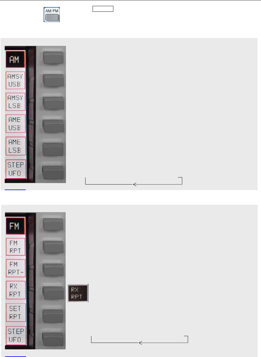
Pressing AM / FM will place the PT-8000 in AM/FM mode whatever has been
the last mode. If the mode is already AM or FM the alternate mode will be
activated.
The according soft key menu (AM or FM) will be called up.
Amplitude Modulation (carrier and two sidebands)
AM Synchronous (carrier and Lower Sideband)
AM Synchronous (carrier and Upper Sideband)
AM single sideband (AME – AM Equivalent) (carrier and Lower Sideband)
AM single sideband (AME – AM Equivalent) (carrier and Upper Sideband
Cyclic change of frequency tuning steps:
→ 1 Hz → 10 Hz → 100 Hz → 1 kHz →
Frequency Modulation (standard mode)
FM repeater mode. The transmit frequency is lower than the receive
frequency (standard). Frequency shift default value is 600 kHz
FM repeater mode. The transmit frequency is higher than the receive
frequency (inverse). Frequency shift default value is 600 kHz
Press and hold to monitor the transmit frequency – squelch is
deactivated ; RX RPT is displayed inverse.
(Only available if repeater mode is selected)
Press to set the frequency shift for repeater mode (see note below)
Cyclic change of frequency tuning steps:
→ 1 Hz → 10 Hz → 100 Hz → 1 kHz →
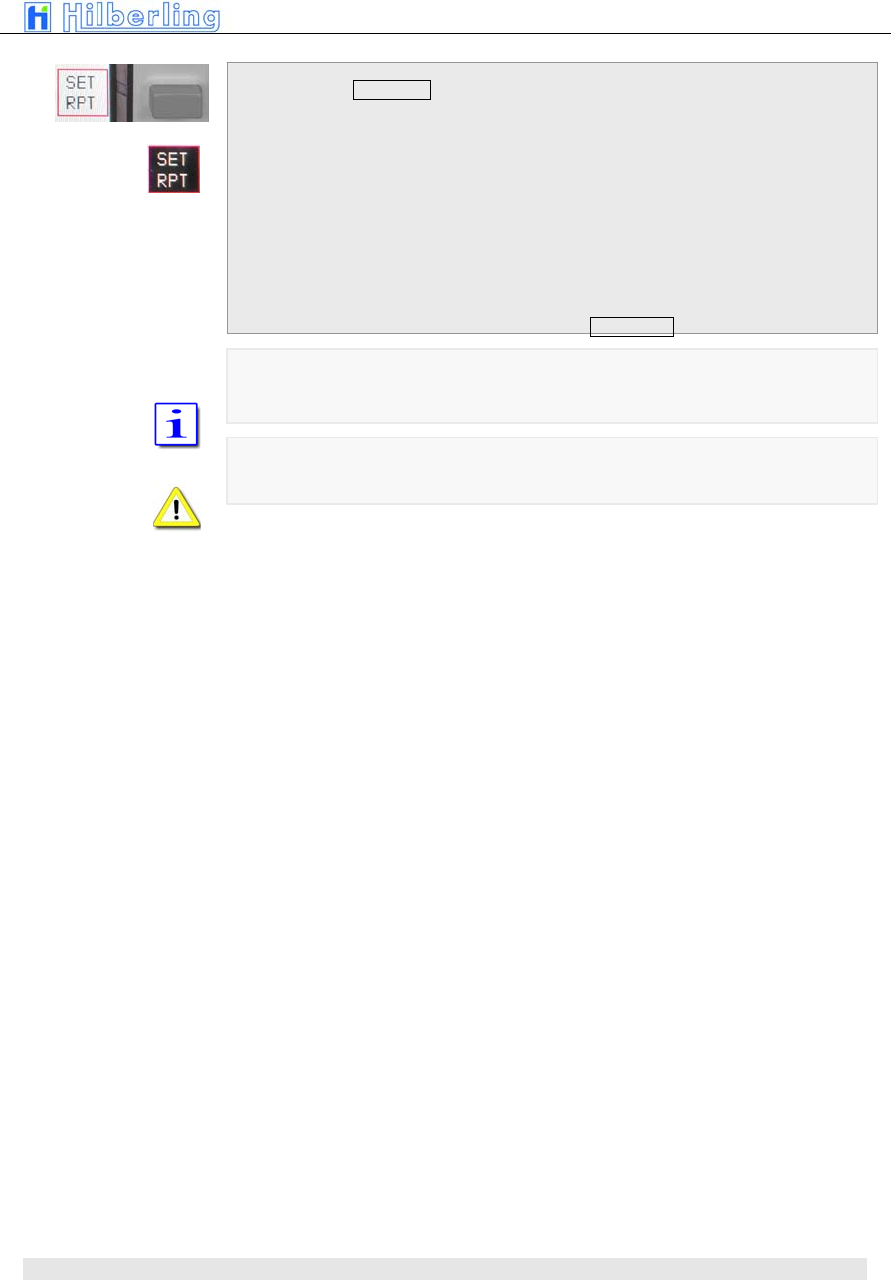
How to set the repeater frequency shift
Picture 30
Picture 31
PT-8000
A
·
B
·
C User Manual C–27
If the soft key SET RPT is depressed
• SET RPT will be inverse
• VFO display will show actual transmit frequency
• Set VFO to desired transmit frequency hence
define the shift within a tuning range from 0 …
2.000kHz.
The frequency resolution selected for the VFO
will apply for this setting.
• Pressing the SET RPT pushbutton again will
terminate the SET RPT modus.
Changing to a different mode will terminate SET RPT as well.
Numerical frequency input not possible
10.4 DATA Transmission
C–28 Part C Installation And Operation
DATA menu
Picture 32
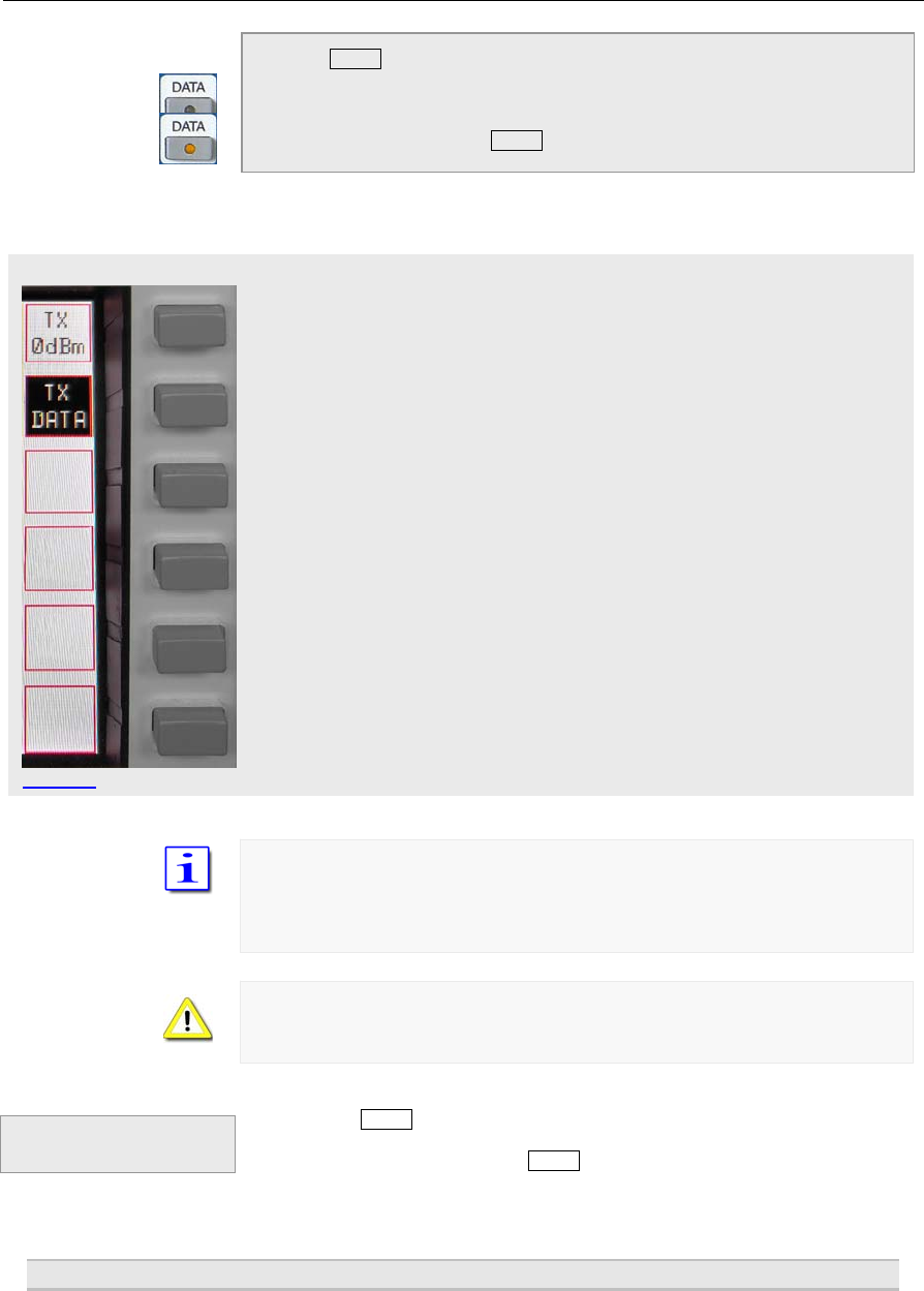
Pressing DATA will call up the DATA soft key menu:
• DATA - LED will turn on
• If ISB mode is activated the ISB menu will be
called up. Otherwise the following menu will be
displayed
•
Signals at the 0dBm input will be transmitted
Signals at the DATA input will be transmitted
TX 0dBm and TX DATA are working alternatively. Only one signal can be
selected
DATA mode may be selected in all modes
If DATA mode is not selected PTT through RS232 handshake signal is not
possible
Pressing the DATA pushbutton again will terminate the DATA modus but only
if the DATA menu is displayed. Call up of this menu is mandatory for the
termination. After termination the DATA-LED will be off.
11 S
ELECTING
F
REQUENCIES
Termination of
DATA Operation
PT-8000
A
·
B
·
C User Manual C–29
To select a frequency four different means are available:
7. Select a BAND
8. Numerical input
9. Recall from a channel
10. Tuning with VFO
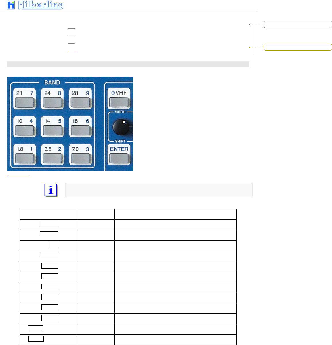
11.1 BAND select
11.1.1 HF BANDS
Pressing a BAND pushbutton selects one of
two stored frequency within the desired BAND.
The last used frequency of this BAND will be
recalled. Pressing BAND again will toggle
between the last two frequencies used within
this BAND.
In case the BAND limits are exceeded trough
tuning the last valid frequency that has been
stored will remain.
Mode and bandwidth are stored together with the respective frequency.
The following BANDS are defined in the PT-8000 software
Pushbutton Band Frequencies
1.8 1 160 m 1.800 ... 2.000 MHz
3.5 2 80 m 3.500 ... 4.000 MHz
n/a 60 m 5.3305 / 5.3465 / 5.3665 / 5.3715 / 5.4035 MHz
7.0 3 40 m 7.000 ... 7.300 MHz
10 4 30 m 10.100 ... 10.150 MHz
14 5 20 m 14.000 ... 14.350 MHz
18 6 17 m 18.068 ... 18.168 MHz
21 7 15 m 21.000 ... 21.450 MHz
24 8 12 m 24.890 ... 24.990 MHz
28 9 10 m 28.000 ... 29.700 MHz
0 VHF + Soft key 6 m 50.000 ... 54.000 MHz
0 VHF + Soft key 2 m 144.000 ... 148.000 MHz
Table 10
Picture 33
Formatted: Bullets and Numbering
Formatted: Bullets and Numbering
C–30 Part C Installation And Operation
VHF menu
A numerical input of a frequency within the selected band will overwrite one of
the two stored frequencies (the last frequency used).
The two stored frequencies of a band are correlated to each VFO. Selecting
the alternate VFO will give access to another two frequencies in that band
(which were used with this VFO). Of course this is applicable for both MAIN-
and SUB-RX.
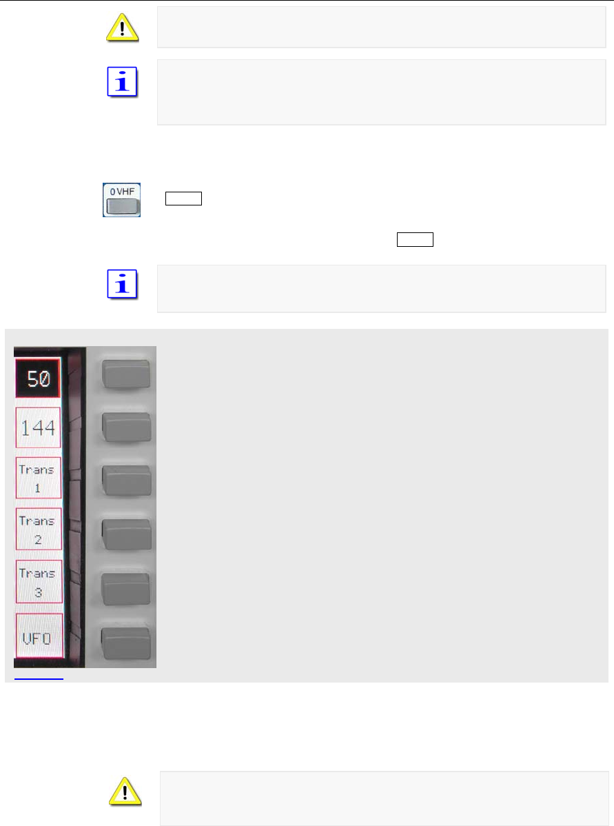
11.1.2 VHF-Bands
Two VHF-bands are covered – 6m (50 MHz) and 2m (144 MHz). Pushing
0 VHF (located in the cluster MODE) will call up the VHF menu and will recall
the last frequency used in VHF (50 MHz or 144 MHz). The respective band
will be displayed inverse. Like on HF the last two frequencies used on VHF
are recalled through the band pushbutton 0 VHF.
If a transverter has been used the last time VHF was activated the respective
softkey will be displayed inverse. The specific transverter will be activated
again.
Activates 6m band (here it is activated). Pushing repeatedly will toggle
between the last two frequencies used in this band
Activates 2m band. Pushing repeatedly will toggle between the last two
frequencies used in this band
Activates transverter #1
Activates transverter #2
Activates transverter #3
VFO menu will be called up
After selecting a tranverter the last used tranverter frequency will be displayed
and the tranverter menu will be called up.
Only one transverter can be activated at a time for each of the receivers. To
operate two transverters MAIN- and SUB-RX must be allocated to different
transverters.
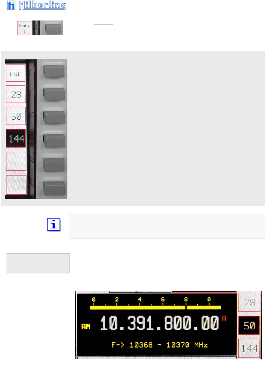
11.1.3 Transverter Operation
Picture 34
PT-8000
A
·
B
·
C User Manual C–31
TRANSVERTER menu
Picture 35
Pushing Trans 1 softkey (VHF menu) will call up allocated Transverter menu
(same applies to the other transverter settings):
Transverter operation 28 MHz band (28 ... 30 MHz)
Transverter operation 50 MHz band (50 ... 52 MHz)
Transverter operation 144 MHz band (142 ... 148MHz)
The allocated band for the transverter will be displayed inverse. If the soft key
is pushed and held the transverter operation frequency band are displayed
instead of the standby VFO frequency.
• Call up VHF menu (pushing = VHF)
• Select transverter #1 … #3
• Selects transverter band – push and hold
respective soft key
Changing of
allocated
transverters
Picture 36
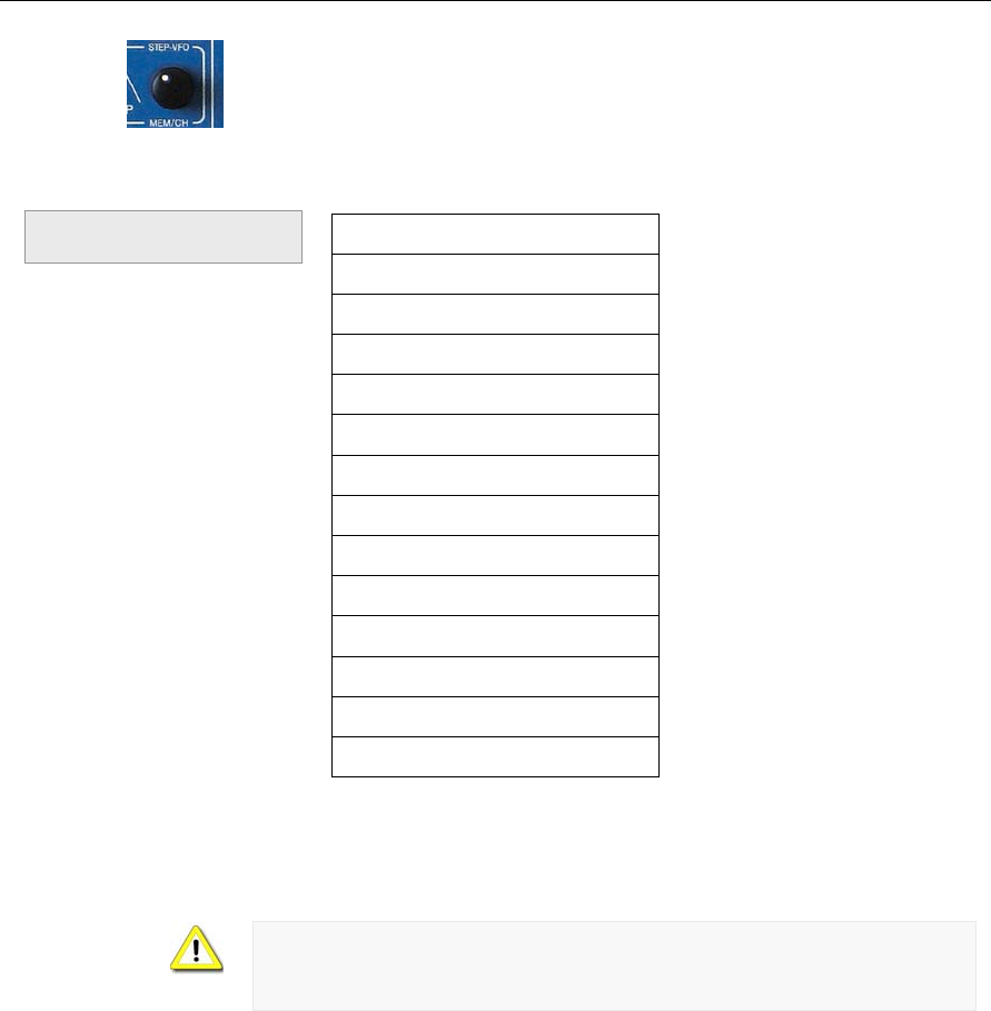
C–32 Part C Installation And Operation
The display shows instead of standby VFO frequency the transverter
operation frequency band. Using control STEP VFO / MEM/CH gives access
to all transverter operation frequency bands as listed below.
Frequencies
432 ... 434 MHz
435 ... 437 MHz
1.268 ... 1.270 GHz
1.296 ... 1.298 GHz
2.320 ... 2.322 GHz
3.400 ... 3.402 GHz
3.456 ... 3.458 GHz
5.760 ... 5.762 GHz
10.368 ... 10.370 GHz
10.450 … 10.452 GHz
24.048 … 24.050 GHz
47.088 ... 47.090 GHz
75.976 ... 75.978 GHz
Table 11
When operating with transverters the TX signal is only available at TX-ext.
J14 at the rear panel. Max. power level at J14 is +20dBm. Hooking up
multiple transverters requires external distribution of TX signals from TX-ext.
J14
Transverter Operation
Frequency Bands
PT-8000
A
·
B
·
C User Manual C–33
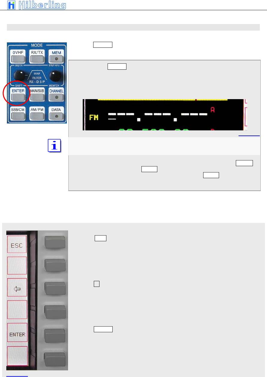
ENTER menu
11.2 Numerical Frequency Input
Pressing ENTER (located in the cluster MODE) will activate the numerical
frequency input.
When pressing ENTER
• The frequency display will show blanks for all
digits. A cursor indicates which field can be
edited.
The number of blanks/digits shown depends on the resolution selected
(see10.4 VFO menu).
• Pressing the respective numbers from 1.8 1 to
28 9 allocated to the BAND buttons (located in
the cluster BAND) and 0 VHF (located in the
cluster MODE) will insert the digits from left to
right.
• The ENTER menu will call up
Pushing ESC soft key will terminate the numerical input. The last used
frequency will be displayed instead. The last used menu will be called up
Pushing deletes the last numerical input. The curser will reappear at the
position
Pushing ENTER soft key acknowledges the frequency input. The last used
soft key menu will be called up.
Pi t 37
Picture 38
Picture 39

C–34 Part C Installation And Operation
It is not necessary to key all digits. Pushing ENTER after the last digit will set
all lower digits to zero. After a valid numerical input is acknowledged the
frequency will be displayed and the respective RX will operate on that
frequency.
After the least significant digit is typed in the numerical input is terminated and
the frequency is transferred to the respective VFO.
In case the input is not acknowledged through ENTER soft key or finished
after 10 seconds the numerical input will be terminated and the last frequency
used will be selected again. The last used soft key menu will be called up.
In case the input frequency is a valid BAND frequency one of the stored
frequency in that BAND will be overwritten by the numerical input.
PT-8000
A
·
B
·
C User Manual C–35
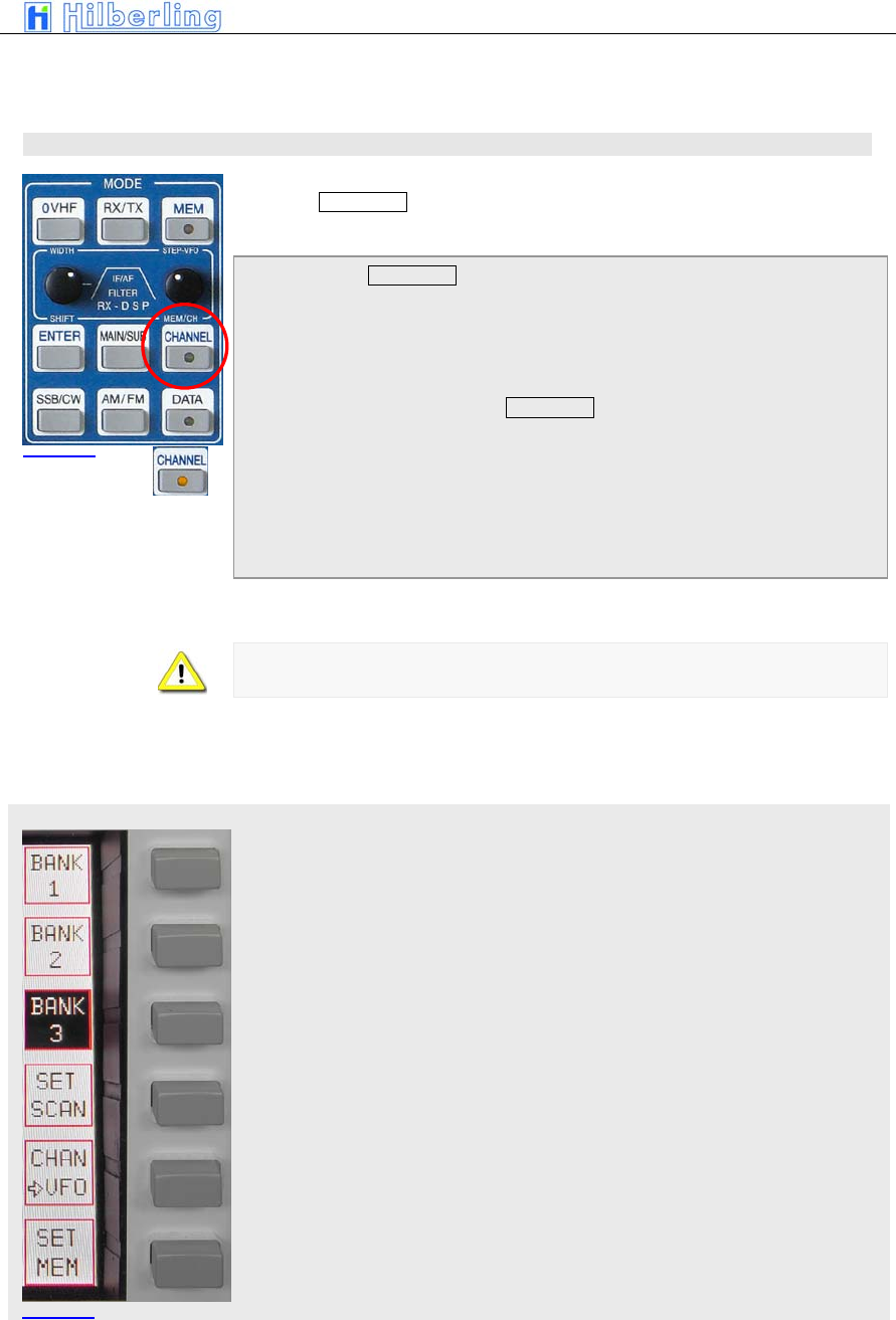
CHANNEL menu
11.3 CHANNEL Operation
Pressing CHANNEL (located in the cluster MODE) gives access to 3 banks
of memory channels each storing 99 frequencies
When pressing CHANNEL
• the last used channel will be activated.
• the CHANNEL LED will be on
• the CHANNEL menu will be called up
• The frequency of the standby VFO will
disappear. Instead information about the active
channel are displayed (see page C24)
When a CHANNEL is selected toggling between MAIN-/SUB-RX and VFO-
A/B is inhibited
The Channel softkey menu offers the following function:
Selecting bank #1
Selecting bank #2
Selecting bank #3
Select (earmark) actual channel for SCAN-Modus
Writing channel to selected VFO (A or B) from active RX (MAIN or SUB)
Writing frequency of selected VFO (A or B) to selected channel
Picture 40
Picture 41

C–36 Part C Installation And Operation
PT-8000
A
·
B
·
C User Manual C–37
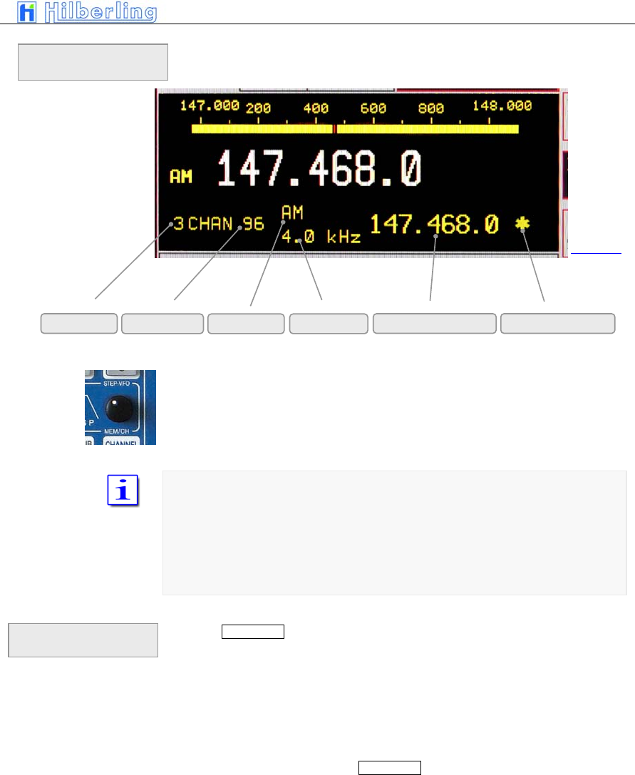
After selecting the memory bank (#1 … #3) the control MEM/CH / STEP-VFO
gives access to the 99 stored frequencies.
Both MAIN- and SUB-RX can read and write into the memory
Channels which are selected for SCAN operation are marked by an asterisk
(*). If the frequency of the marked channel lies within the SCAN boundaries it
will be used for SCAN operations.
Pushing CHANNEL again will terminate the CHANNEL operation:
• the last used VFO frequency will be activated
• the channel menu will be called up again in case
a different soft key menu was activated during
channel operations
• otherwise the channel soft key menu will be left
and the last used soft key menu will be called up
• the CHANNEL LED will be off
CHANNEL
information display
Termination of
CHANNEL Operation
Bank # Channel # Mode Bandwidth Stored Frequency SCAN identifier
Picture 42
C–38 Part C Installation And Operation
VFO menu
11.4 MAIN Tuning Knob
Primary means of tuning the active RX (Main- or SUB-RX) is the main tuning
knob.
General frequency coverage is 9 kHz to 54 MHz and 110 MHz to 170 MHz.
Due to the frequency scheme of the PT-8000 the frequency from 54 MHz to
110 MHz is blanked out.
Transmit operation is only possible on the allocated amateur radio bands (see
Tab on page C20)
In case the transmit boundaries are to be modified (commercial application;
new amateur radio frequencies) please contact Hilberling GmbH for further
information about a software update.
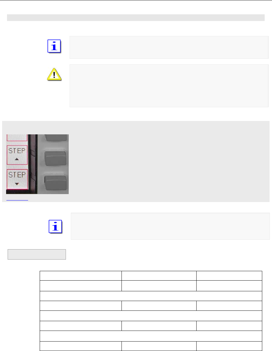
The tuning increments are adjustable through STEP selection, which is
allocated to the VFO soft key menu.
STEP up (towards fine tuning) decreases the tuning increments by power of
10. Additional digits appear at the VFO frequency readout
STEP down (towards coarse tuning) increases the tuning increments by
power of 10. Lesser digits appear at the VFO frequency readout
The selectable increments are 1 Hz / 10 Hz / 100 Hz / 1 kHz.
Not displayed digits are set to 0.
VFO frequency displayed Transceiver-Frequency Tuning with
1.234.567 1.234,567 kHz 1 Hz increments
1st pushing STEP up
1.234.56 1.234,560 kHz 10 Hz increments
2nd pushing STEP up
1.234.5 1.234,500 kHz 100 Hz increments
3rd pushing STEP up
1.234 1.234,000 kHz 1 kHz increments
Table 12
Example
Picture 43
PT-8000
A
·
B
·
C User Manual C–39
Pushing STEP down will initiate the reverse process towards fine tuning
Each mode has been allocated a default tuning increment setting
AM / FM: 100 Hz
SSB / CW: 10 Hz
Changing modes will reset the current setting to the default values.
11.5 STEP-VFO Control
The STEP-VFO Control is placed in the cluster MODE. The control enables to
tune in 10 kHz, 100 kHz and 1 MHz increments.
Pushing the knob activates the STEP-VFO function:
• A curser appears at the 100 kHz digit of the
frequency display.
Turning the knob will now tune the VFO by 100 kHz steps. Pushing the knob
a second time will move the curser to the 10 kHz digit. Turning the knob will
result in tuning the VFO by 10 kHz steps. Pushing the knob another time will
display the curser under the 1 MHz digit – hence tuning can now be
established by 1 MHz steps.
Pushing the knob again will result in a movement of the curser again to the
100 kHz digit, then 1 kHz and 1 MHz again.
Neither pushing the knob nor turning the control for more than 3 seconds will
terminate the STEP-VFO function. If re-activated by pushing the knob the
cursor will be at the place used at last.
When power up the PT-8000 the curser will initially alway occur at the 100
kHz (default value) position when activating STEP-VFO.
Picture 44
Picture 45
C–40 Part C Installation And Operation
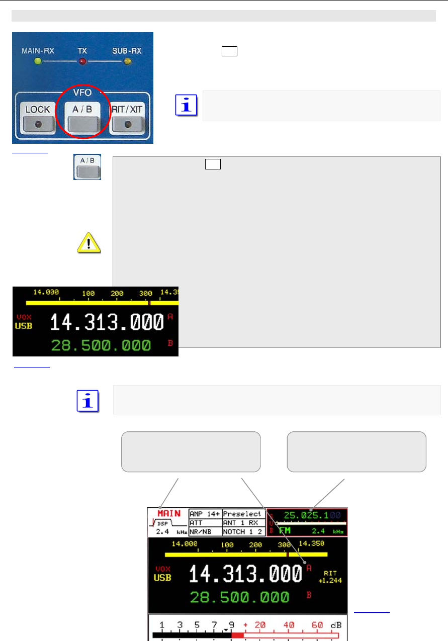
11.6 VFO Management
Both receivers (MAIN- and SUB-RX) have its own VFOs – VFO A
and VFO B. Switching between VFO A and VFO B is established
through VFO A/B pushbutton. The button is located in the cluster
VFO.
In addition to the frequencies the VFOs store the filter
(bandwidth) and mode information.
When pressing VFO A/B:
• In case the VFO softkey menu is already
displayed the respective RX will change its VFO
(A=>B or B=>A).
• If a different softkey menu is displayed the first
push of VFO A/B will call up the VFO softkey
menu. The second push will alter the VFO A an
VFO B.
• Both frequencies displayed for the active RX will alter its
position. The white display always shows the selected
VFO. The VFO can be identified through the red
nominators A/B.
• The smaller green display always shows the alternate
VFO that is not selected and in red its identifier.
Only the SUB-RXs selected VFO frequency is displayed without its identifier.
Active RX
(shown MAIN-RX)
selected VFO (shown VFO A)
RX in background
(shown SUB-RX)
F
r
e
q
uenc
y
of selected VFO
Picture 46
Picture 48
Picture 47
PT-8000
A
·
B
·
C User Manual C–41
VFO menu MAIN
VFO menu SUB
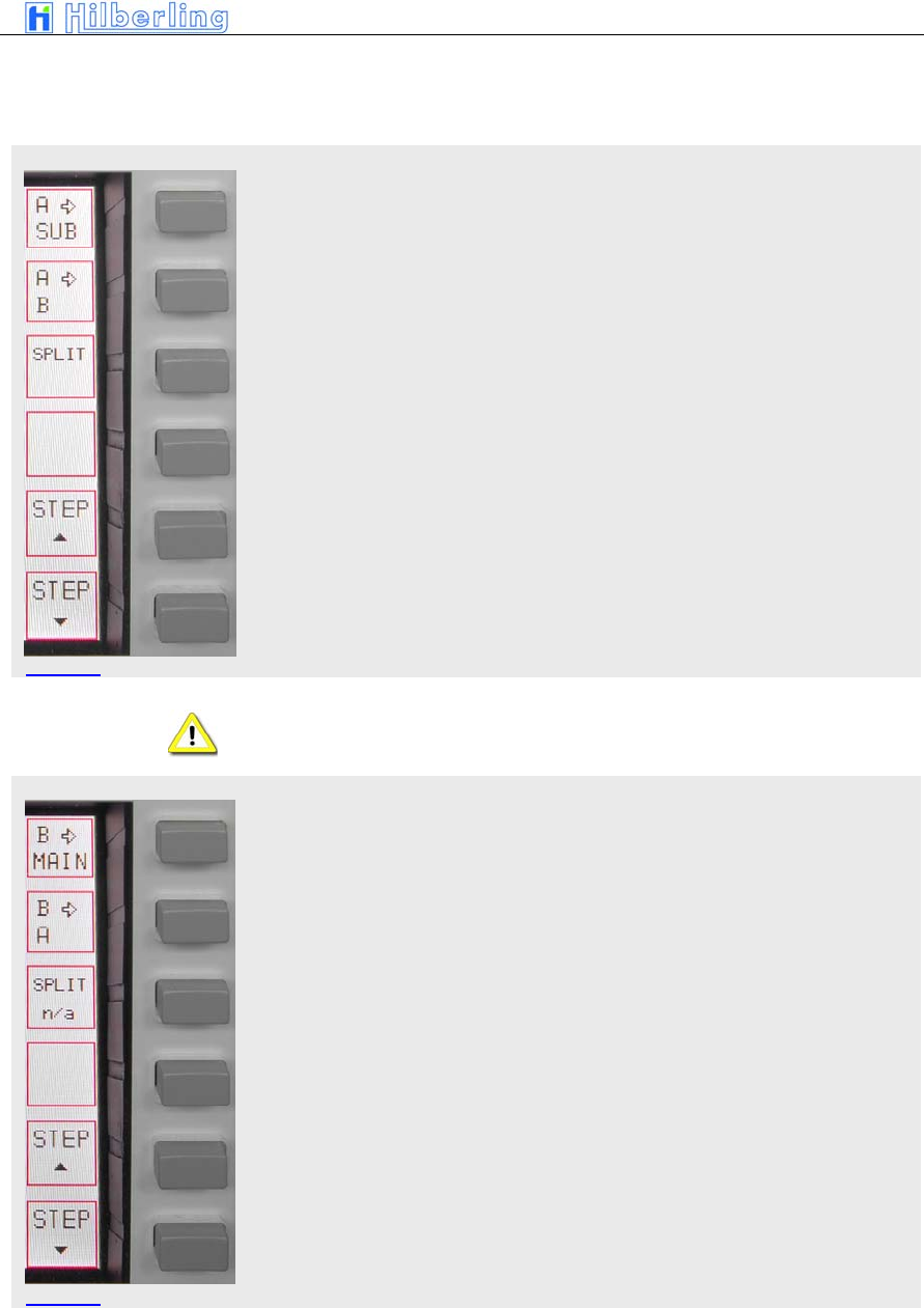
The VFO softkey menu offers the following function:
The frequency of the selected VFO (shown VFO B) from the active RX
(shown MAIN-RX) is copied to the selected VFO from the SUB-RX
The frequency of the selected VFO (shown VFO B) is copied to the alternate
VFO
VFO SPLIT: The Frequency of the selected VFO (shown VFO B) will be used
for receive; the alternate VFO (shown VFO A) will determine transmit
frequency
SPLIT operation using VFO A and VFO B (= “VFO SPLIT”) is only possible
with the MAIN-RX.
The frequency of the selected VFO (shown VFO B) from the active RX
(shown SUB-RX) is copied to the selected VFO from the MAIN-RX
The frequency of the selected VFO (shown VFO B) is copied to the alternate
VFO
VFO SPLIT not applicable for SUB-RX
Picture 49
Picture 50

C–42 Part C Installation And Operation
11.7 SPLIT Operation
There are various ways to split between transmit- and receive frequencies.
Keep in mind that the PT-8000 represents a transmitter with two identical
receivers. However, to link a receiver with the transmitter as a transceiver is
only possible with the MAIN-RX. Hence only the MAIN-RX VFOs can
determine the transmit frequency.
Three ways for SPLIT operation are available:
• Operating with MAIN-RX using SPLIT VFO
function as described in 11.6.
This is the “regular” method which gives you
quick access to the desired SPLIT.
This way the resources of the PT-8000 are used
economical.
• Tuning MAIN-RX on the desired transmit
frequency and using SUB-RX for receive.
This way you can listen to the transmit and to the
receive frequency simultaneously which can give
some advantages in difficult (crowded)
environments. However all resources of the PT-
8000 are used. The SUB-RX can not be tasked
with other valuable operations like band
monitoring, transverter operation etc.
• Using MAIN-RX and detuning RX or TX through
RIT and XIT.
The least elegant method. SPLIT is limited to
10kHz.
SPLIT Operation using VFO SPLIT function
Tune with VFO A to the station you would like to call. Select VFO B and tune
to the desired transmit frequency. Make sure the same mode is selected.
Reselect VFO A. Press SPLIT. Now VFO A is for receive and VFO B is for
transmit.
Of course you can tune with VFO B to receive and tune VFO A to the
(split)transmit frequency. Selecting SPLIT will always chose the alternate VFO
for transmit. Pressing VFO A/B will alternate RX and TX frequencies.
Pressing SPLIT again will terminate SPLIT operation.
The actual operating frequency in RX/TX will always be displayed as the
selected VFO frequency; i.e. during SPLIT the display will change with T/R
switching.
SPLIT Operation using MAIN-RX and SUB-RX
Tune with SUB-RX (either VFO) to the station you would like to call. Tune with
MAIN-RX to the desired transmit frequency. You can monitor the stations
calling and the station to be called simultaneously. This might give
advantages in crowded environments. Use the volume control for MAIN and
SUB to adjust convenient monitoring.
SPLIT Operation using RIT/XIT
Tune with MAIN-RX to the frequency of the station you want to call. Engage
XIT and select an offset that you desire to call the station.
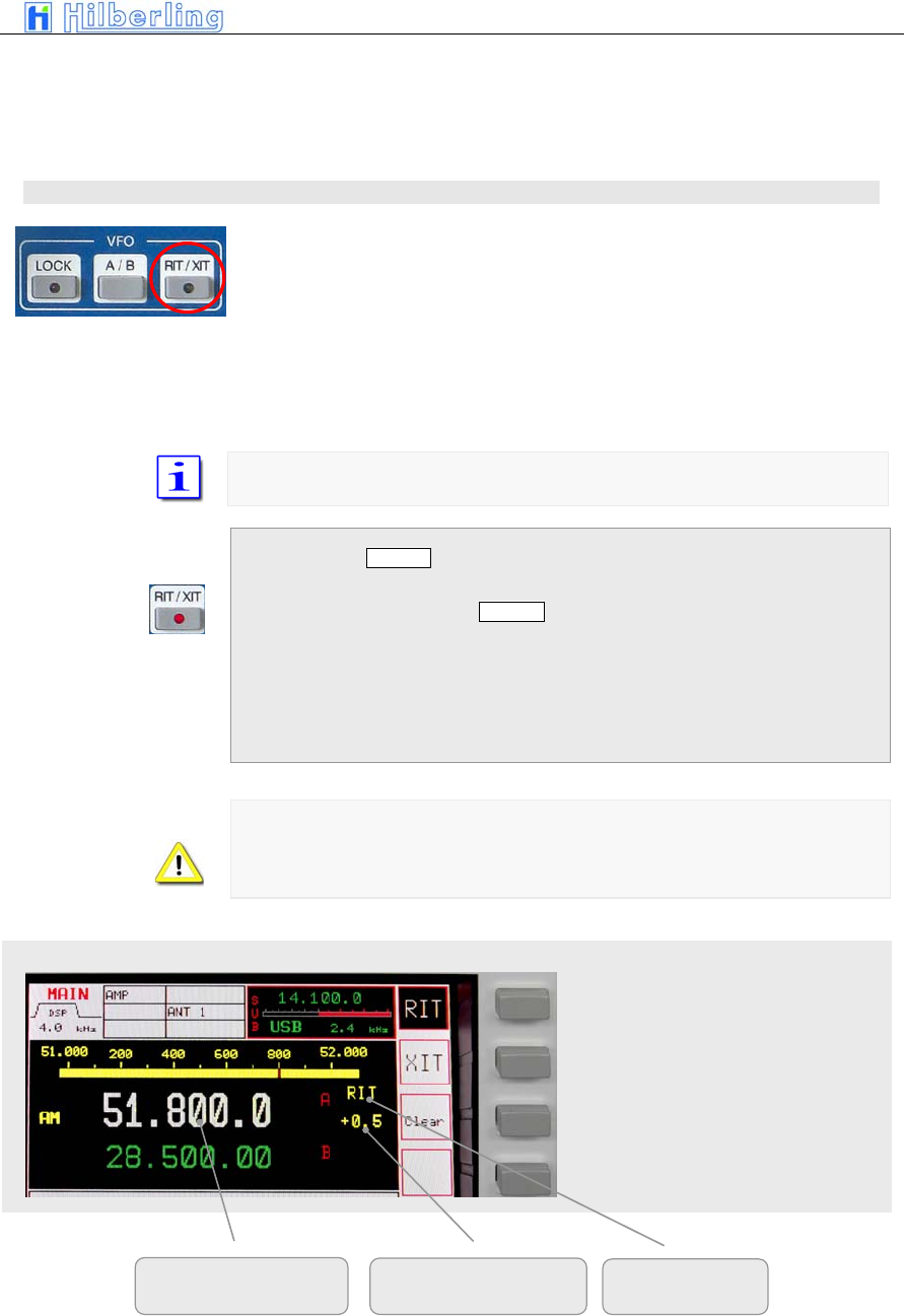
PT-8000
A
·
B
·
C User Manual C–43
RIT/XIT menu / RIT/XIT offset
Tune MAIN-RX to the desired transmit frequency to call a station that works
split. Engage RIT and tune RIT to receive the station you want to call.
The offsets for XIT/RIT are limited to 9.999kHz.
11.8 RIT / XIT
RIT (Receiver Incremental Tuning) allows to shift/adjust the receiving
frequency plus/minus 9.999 kHz from the transmit frequency. The MAIN-RX
and the transmitter are no longer „transceive“. RIT is only possible with the
MAIN-RX.
XIT (Transmitter Incremental Tuning) allows to shift/adjust the transmitting
frequency plus/minus 9.999 kHz from the receiving frequency. The MAIN-RX
and the transmitter are no longer „transceive“. RIT is available with the MAIN-
RX only.
The tuning range of RIT/XIT is always plus/minus 9.999 kHz
When pushing RIT/XIT located in the cluster VFO:
• RIT/XIT-LED will be on
• The RIT/XIT softkey menu will be called up - RIT
or XIT are displayed inverse to show status
• CLAR control is enabled
• RIT or XIT and the offset is displayed right next
to the frequency
In case of RIT only the display will show the actual frequency resulting from
the RIT offset. During XIT always the receiving frequency will be displayed.
The status RIT or XIT will be shown in the display together with the offset
adjusted.
Activate RIT (shown)
Activate XIT
Clear the offset to 0
Only for RIT: resulting
RX fre
q
uenc
y
Offset RIT and XIT RIT or XIT
Pi t 51
Pi t 52
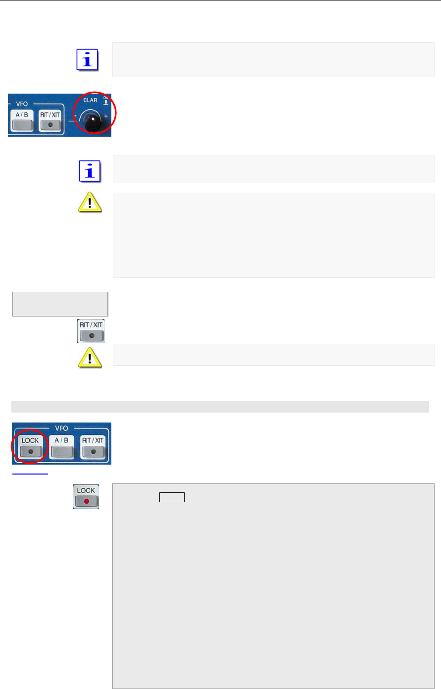
C–44 Part C Installation And Operation
When activating RIT/XIT the last used status (RIT or XIT) will be selected.
Pushing RIT/XIT again will terminate the RIT/XIT function.
To adjust the offset frequency turn the knob called CLAR (clarifier) located
next to the cluster VFO.
The tuning increments of the CLAR control is identical to the selected STEP
rate.
RIT/XIT are not available for SUB-RX.
In case the SUB-RX is the active oneXIT/RIT and the offset are no longer
displayed.
In case the SUB-RX is the active one and XIT is activated for the MAIN-RX,
pushing PTT will display the MAIN-RX as the active one. XIT and the offset
are indicated.
If the RIT/XIT softkey menu is displayed pushing RIT/XIT will terminate this
modus. If the menu is not displayed pushing RIT/XIT will call it up and a
second push will terminate ROT/XIT operation.
The RIT/XIT-LED will extinguish.
Changing MODE will always terminate RIT/XIT operation
11.9 LOCK Function
All controls that will have an effect on the frequency selected can be locked
through pushing LOCK which is located in the cluster VFO.
Engaging LOCK will turn its LED on
The following controls (knobs, buttons) are effected by LOCK:
• MAIN-RX VFO
• SUB-RX VFO
• STEP-VFO
• BAND
• CHANNEL / MEM
• RIT / XIT
Termination of
RIT/XIT operation
Pi t 53
Picture 54
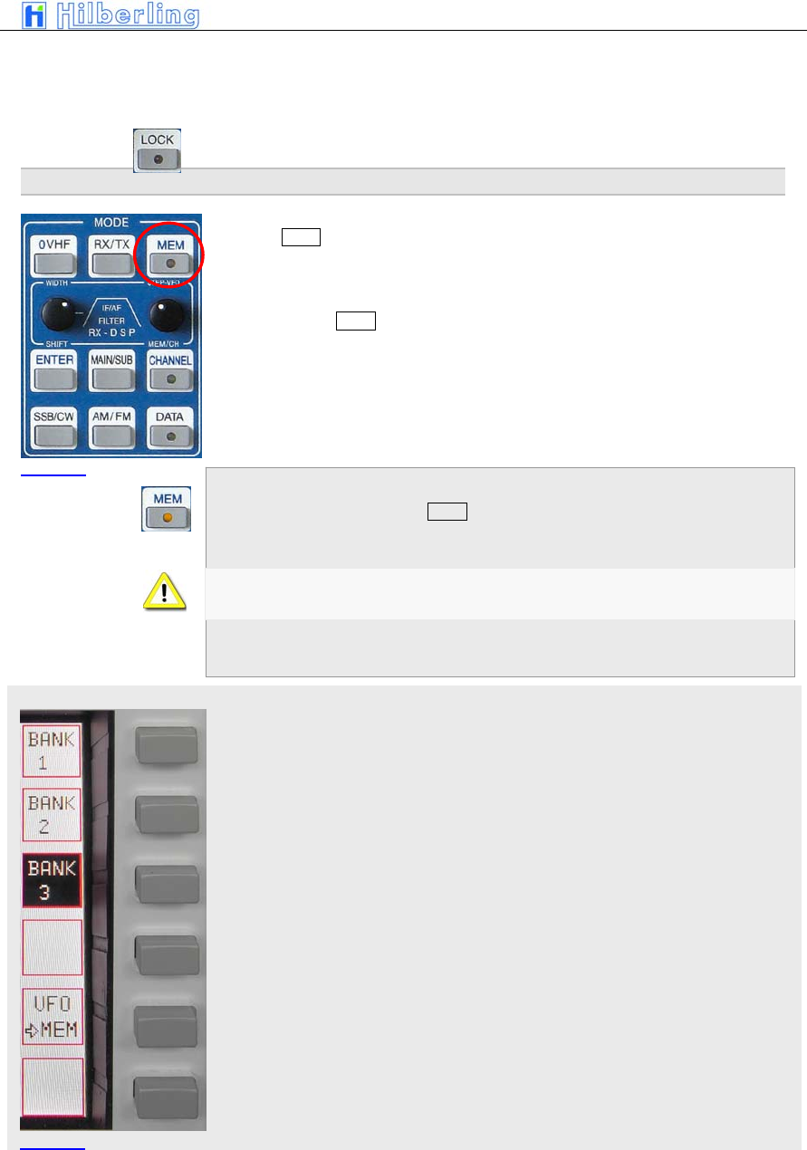
PT-8000
A
·
B
·
C User Manual C–45
MEM menu
• MAIN / SUB
• VFO A / B
• MODE
Pushing LOCK again will terminate locking of controls.
12 M
EMORY
O
PERATION
(MEM)
Pushing MEM in the cluster MODE will store the frequency of the active RX to
one of the 99 memories organized in thee banks.
Other than CHANNEL operation (see page C-23) the RX will stay on its tuned
frequency while MEM functions are executed.
• MEM-LED will be on
When activating MEM toggling between MAIN- and SUB-RX and VFO-A/B
are inhibited.
• MEM softkey menu will be called up:
Selecting bank #1
Selecting bank #2
Selecting bank #3
Write displayed VFO frequency of active RX to selected memory (see below).
MODE and filter selection will be stored as well.
Picture 55
Picture 56
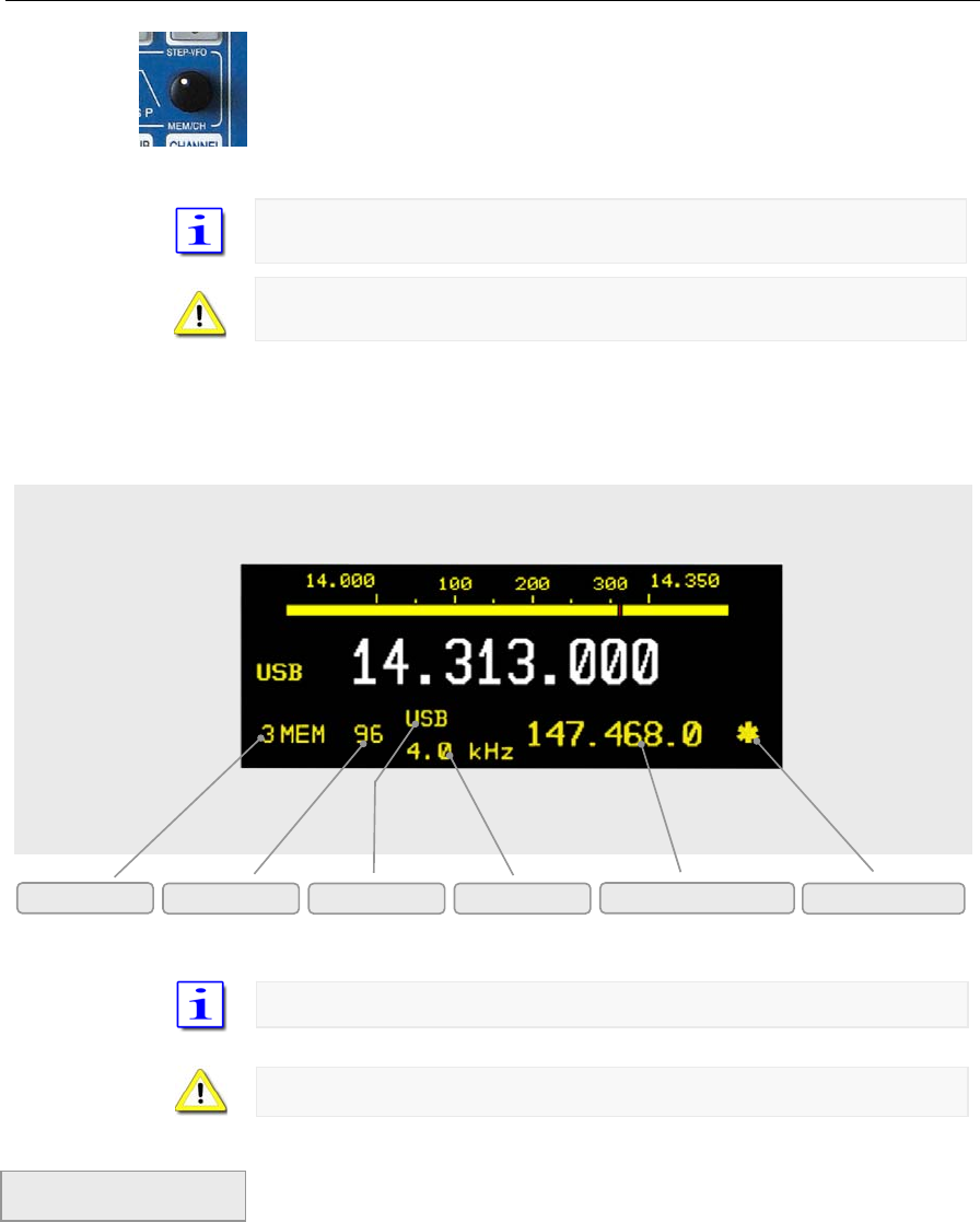
C–46 Part C Installation And Operation
Display Information
Pushing softkey BANK 1, BANK 2 and BANK 3 gives access to other banks.
Use MEM/CH to select desired memory/channel. Pushing softkeys VFO >
MEM“ will write the VFO frequency to the selected memory.
Always the last used bank # is selected and displayed with its first empty
memory
In case all memories are written the last used memory will be displayed and
overwritten.
• The frequency display of the standby VFO will
be substituted by the information shown below:
Memories are accessible from both MAIN- and SUB-RX.
When attempting to overwrite memories there will be no warning.
If the MEM softkey menu is displayed pushing MEM will terminate this modus.
If the menu is not displayed pushing MEM will call it up and a second push
will terminate MEM operation. MEM-LED will turn off.
Bank # Memory # Mode Bandwidth Stored Frequency SCAN Marker
Pi t 57
Termination of
MEM modus
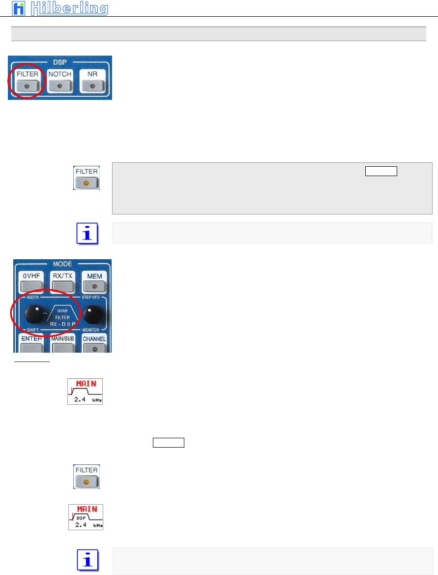
PT-8000
A
·
B
·
C User Manual C–47
13 F
ILTER
B
ANDWIDTH AND
S
HIFT
F
UNCTION
(W
IDTH
/S
HIFT
)
Filtering in the PT-8000 is obtained by Roofing Filters (1st IF @ 70.7 MHz)
and Channel Filters (2nd IF @ 10.7 MHZ). The channel filters can be further
enhanced by a DSP (Digital Signal Processing) working in the audio range.
The DSP filtering will:
• Interpolate between analogue filter bandwidths
• Sharpen the filter flanks
• Shift the placement of the filters
Acitvating DSP filtering is accomplished by the pushbutton FILTER in the
cluster called DSP. If DSP filtering is engaged, FILTER-LED is on.
After power on the DSP filters are off (Default value).
Appropriate roofing filters are selected automatically
WIDTH and SHIFT control located in the cluster MODE is used to adjust the
filter bandwidth and to shift the passband across the spectrum.
Pushing the knob will toggle between WIDTH and SHIFT function.
In case the FILTER-LED is off only the analogue (Xtal) filters are active. The
selected bandwidth is dispayed and graphically expressed.
The position of the passband relative to the carrier frequency (represented by
a vertical line) is indicated as well.
Pushing FILTER button will activate the DSP. Additional filter will enhance the
overall filter response:
FILTER-LED will be on
The display will indicate DSP operation
Depending on the MODE there are analogue filters available which are
interpolated in bandwidth by the DSP.
Pi t 58
Picture 59

C–48 Part C Installation And Operation
Depending on MODE the following Xtal-filters (analogue filters) and passband
shifts are available (using WIDTH and SHIFT control):
Width 1.8 / 2.0 / 2.4 / 2.7 / 3.1 / 6.0 kHz
Shift 100 Hz - 600 Hz in 100 Hz steps
The 2.7 kHz filter is the allocated roofing filter for SSB
Width 0.5 / 1.8 kHz
Shift/Pitch 400 Hz – 10000 Hz in 100 Hz steps
The 2.7 kHz filter is the allocated roofing filter for CW
Width 6.0 / 15 kHz
Shift n/a
The 6.0 and 12.0 kHz filter are the respective roofing filter for AM
Width 6.0 / 7.5 / 15.0 kHz
Shift n/a
The 6.0 / 7.5 and 12.0 kHz filter are the respective roofing filter for FM
For 7.5 and 15.0 kHz the 10.7 MHz Xtal filters are bypassed.
For FM the “bandwidth” is related to the audio response only; RF-bandwidth
remains always 6 or 12 kHz respectively
Depending on MODE the following bandwidths (through the combination of
digital and analogue filters) and passband shifts are available (using WIDTH
and SHIFT control):
Width 1.0 / 1.2 / 1.4 / 1.6 / 1.8 / 1.9 / 2.0 / 2.1 / 2.2 / 2.3 / 2.4 / 2.5
2.6 / 2.7 / 2.8 / 2.9 / 3.0 / 3.1 / 3.2 / 3.3 / 3.4 / 3.5 / 4.6 / 6.0 kHz
Shift 0 Hz – 600 Hz in 50 Hz steps
The 2.7 kHz filter is the allocated roofing filter for SSB
Width 50 / 100 / 200 / 400 / 500 / 600 / 800 / 1000 Hz
Shift/Pitch 400– 1000 Hz in 50 Hz steps
The 2.7 kHz filter is the allocated roofing filter for CW
Width 4 / 5 / 7 / 8 kHz
Shift n/a
The 6.0 and 12.0 kHz filter are the respective roofing filter for AM
Width 2.4 / 2.5 / 2.6 / 2.7 / 2.8 / 2.9 / 3.0 / 3.1 / 3.2 / 3.3 / 3.4 / 3.5
4.6 / 6.0 / 7.5 kHz / 8.0 kHz (Bypass)
Shift n/a
The 6.0 and 12.0 kHz filter are the respective roofing filter for FM
For > 4.6 kHz the 10.7 MHz Xtal filters are bypassed.
For FM the “bandwidth” is related to the audio response only; RF-bandwidth
remains always 6 or 12 kHz respectively
DSP OFF
LSB/USB
CW
AM
FM
DSP ON
LSB/USB
CW
AM
FM
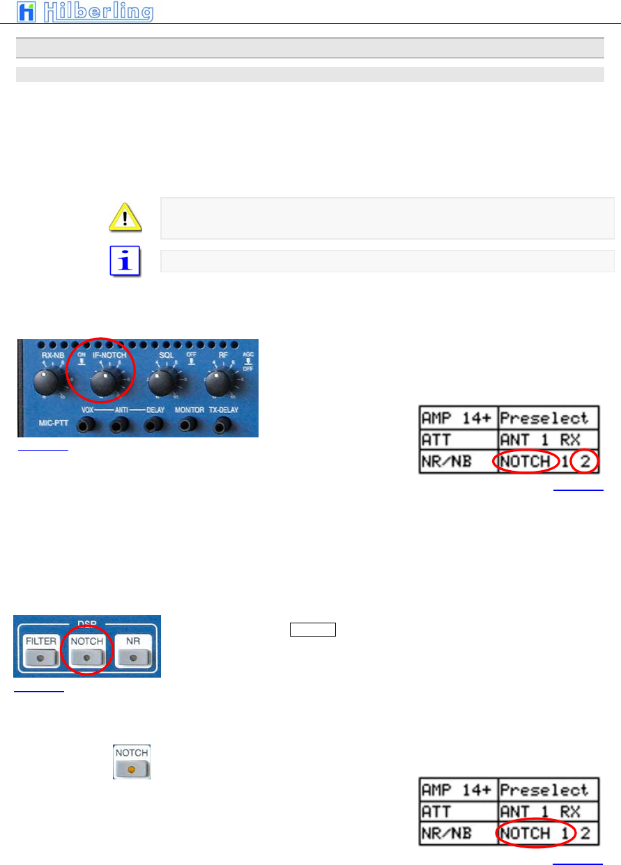
PT-8000
A
·
B
·
C User Manual C–49
14 N
OTCH
/
N
OISEREDUCTION
/
N
OISEBLANKER
14.1 Notch Filter Functions
Two Notch filter of different type are available in the PT-8000. One is working
at 1st IF 70.7 MHz – it´s the classical type of manual notch filtering using a
Xtal bridge – the IF-NOTCH. The other one is part of the DSP – it´s an
Automatic Notch Filter (ANF) – here called the DSP NOTCH.
DSP NOTCH and IF-NOTCH may be engaged simultaneously.
Notch filtering is not available in AM and FM. In case NOTCH filtering is active
and modes are changed to AM/FM both NOTCHs will cease operation.
After power on both NOTCH filters are off (Default value).
14.1.1 IF-NOTCH
The IF-NOTCH will be activated by pushing the control IF-
NOTCH which is located as depicted. On the display it is
outlined as NOTCH 2.
• The display will show NOTCH 2
• Turning IF-NOTCH will adjust the varable notch
through the passband hence the interference will
be almost nullified.
14.1.2 DSP-NOTCH
Pushing the button NOTCH located in the cluster DSP will activte the
automatic notch filtering. On the display the DSP NOTCH is outlined as
NOTCH 1.
The DSP will now detect even multiple interferences and will cancel them
effectively.
• DSP NOTCH-LED will be on
• The display will show NOTCH 1
Picture 60
Picture 61
Picture 62
Picture 63
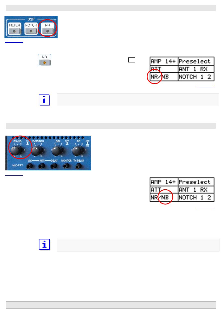
C–50 Part C Installation And Operation
14.2 Noise Reduction
Pushing the button NR located in the cluster DSP will active the Automatic
Noise Reduction (ANR or NR). On the display the DSP NR is outlined as NR.
• DSP NR-LED will be on
• The display will show NR
After power on NR is off (default value)
14.3 Noise Blanker
The RX-NB will be activated by pushing the control RX-NB
which is located as depicted. On the display it is outlined
as NB.
• The display will show NOTCH 2
Turning the RX-NB control will adjust the threshold of the noise blanker to the
specific situation. Noise is dramatically reduced hence improving the
readability of weak signals.
After power on NR is off (default value)
15 S
QUELCH
Picture 64
Picture 65
Picture 66
Picture 67
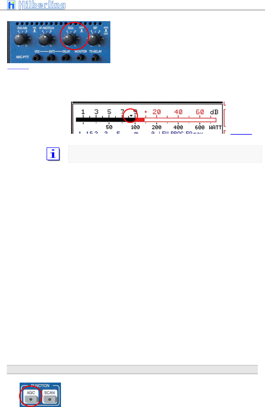
PT-8000
A
·
B
·
C User Manual C–51
The SQUELCH (SQ) will be activated by pushing the
control SQL which is located as depicted.
The threshold for squelch operation is adjusted by turning
the knob. Observing the S-Meter one can monitor the
threshold adjustment through the squelch marker
(triangle).
A triangle is moving in the S-meter according to the threshold setting of the
SQL control.
Once the SQL is activated and the threshold has engaged i.e. the RX is silent,
push and hold the SQL to override the threshold momentarily.
16 RX
G
AIN
C
ONTROL
(AGC
/
RF-GAIN)
Picture 68
Picture 69
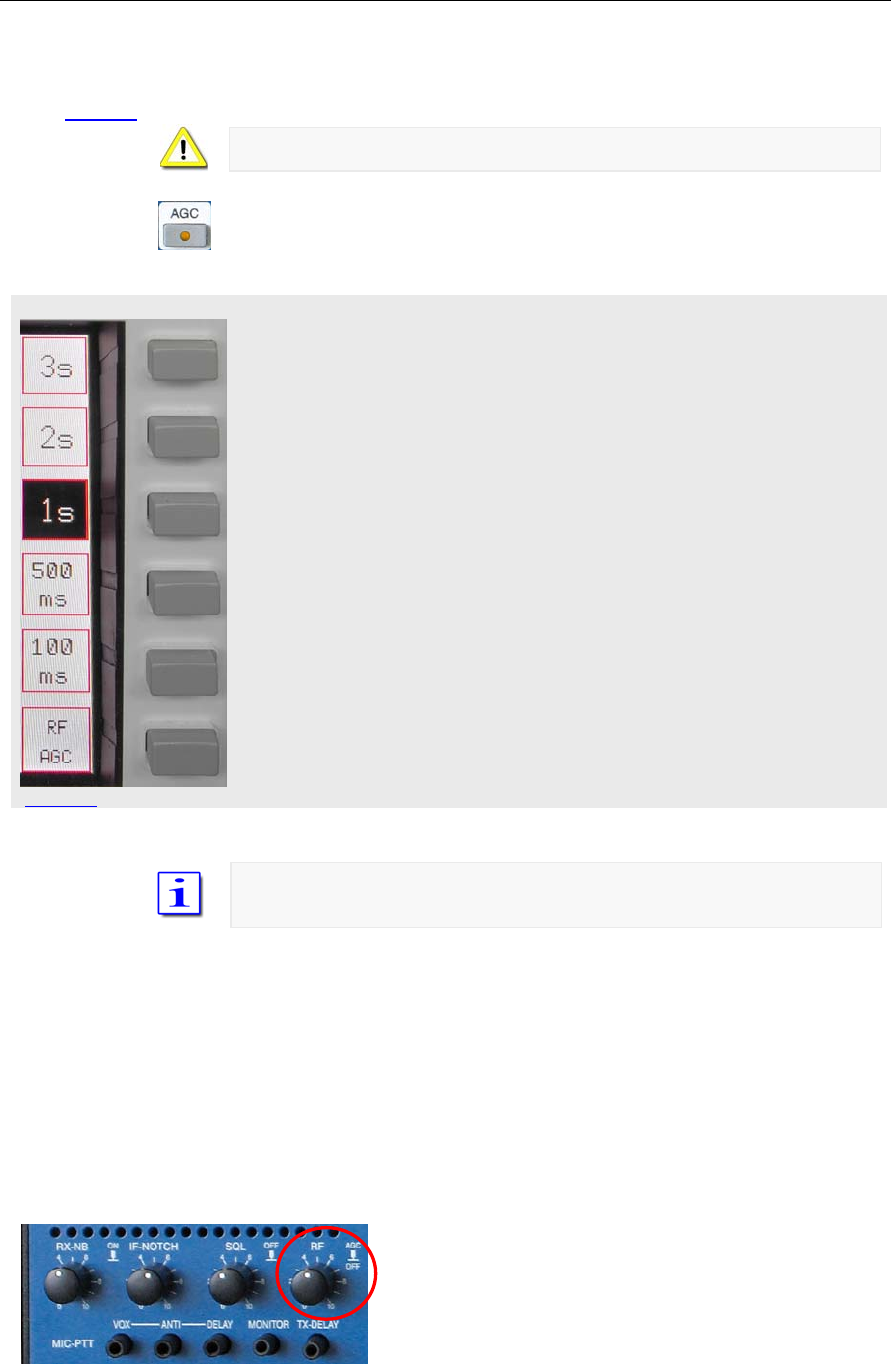
C–52 Part C Installation And Operation
AGC menu
Picture 71
The AGC (Automatic Gain Control) is active after power on, its hang time is 2
seconds (default value). Manual control of the AGC system is initiated through
the AGC pushbutton located in the cluster FUNCTION.
AGC-LED is off during standard operation.
Pushing AGC will call AGC menu
• AGC-LED will be on.
• The AGC softkey menu will be called up:
Select AGC hang time 3 sec
Select AGC hang time 2 sec (default value)
Select AGC hang time 1 sec
Select AGC hang time 500 msec
Select AGC hang time 100 msec
The key toggles between RF-AGC / Audio-AGC (see below)
To prevent missing of weak signals during tuning the MAIN- or SUB-RX AGC
hang time will be always 100 msec.
The AGC-voltage is derived from the RF-signal after it has passed the
channel filters (10.7 MHz). The DSP will narrow the passband – hence out of
(DSP)- filter signals may still derive AGC voltage. This can be annoying
especially during CW operation. The solution is to switch to Audio-AGC.
AGC is derived from the audio to overcome situations described above.
Normal operation is RF-AGC.
Picture 70
RF-AGC
Audio-AGC
PT-8000
A
·
B
·
C User Manual C–53
The control knob RF is located as depicted. It allows to cut
off AGC action by pushing and to adjust an RF threshold
by turning.
AGC threshold
Turning the control RF will adjust the AGC threshold to a level which can be
monitored by observing the S-Meter. The AGC threshold can be raised to a
certain level where signals below are significantly less audible than signals
above the threshold where AGC action will level out the audio.
AGC OFF
Pushing the RF control will cut off any AGC action.
• 1. The display will show AGC-OFF
• 2. AGC-LED will be on
• 3. S-Meter will fall back to zero
In case a signal is present the audio volume may exceed the comfort level
Turning the RF control allows to adjust the RF gain according to the situation.
17 F
REQUENCY
S
CANNING
(SCAN)
Picture 72
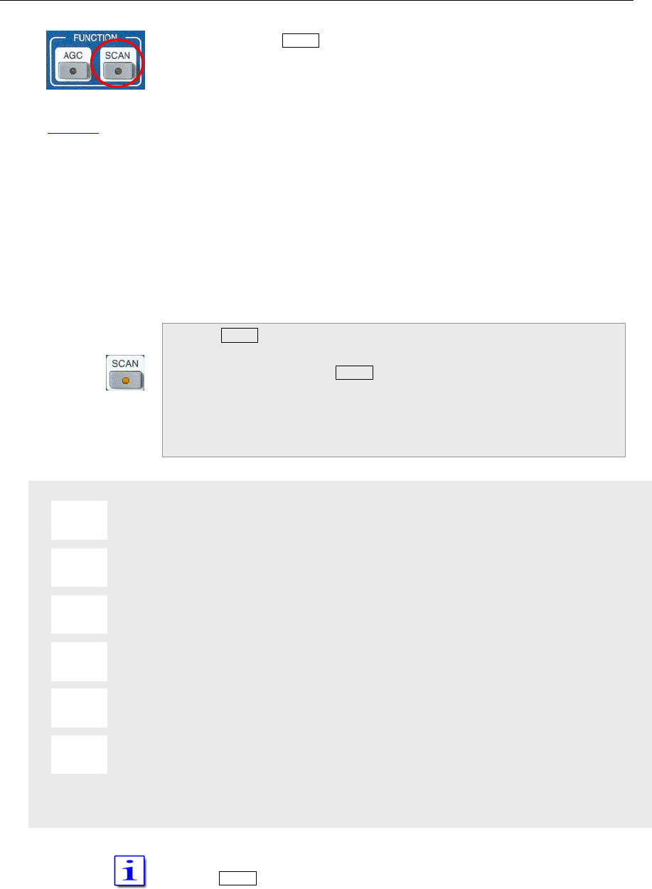
C–54 Part C Installation And Operation
SCAN menu
Pushing the button SCAN located in cluster FUNCTION will activate scanning
of channels which are earmarked for scanning (see page C33). The receiver
will scan any frequency between 9 kHz and 29.999 MHz, and it will scan
frequencies from 50.0 to 54.0 MHz and 144.0 to 148.0 MHz.
These frequencies will be checked for a signal.
The RX will scan the channels from lower to higher frequencies with the
stored MODE and bandwidth.
• If the squelch is engaged scanning will Stopp
when a signal on a scanned channel opens the
squelch
• If the squelch is open, the RX will pause on the
scanned frequency for a time defined. After this
time has elapsed the scanning will continue.
• If the squelch engages during the pause
scanning will continue immediately
Pushing SCAN will:
• SCAN-LED will be on
• The frequency of the standby VFO will
disappear. Instead information about the
scanned channel is displayed as in channel
modus (see page C33)
• SCAN softkey menu will be called up
Delay time is 5 seconds
Delay time is 10 seconds
Delay time is 15 seconds
Delay time is 20 seconds
Delay time is 25 seconds
Delay time is infinite
Scanning will be terminated upon activating PTT, VFO tuning, STEP-VFO or
pushing SCAN. The frequency of the stanby VFO will reappear.
5 s
10 s
15 s
20 s
25 s
∞
Picture 74
Pi t 74
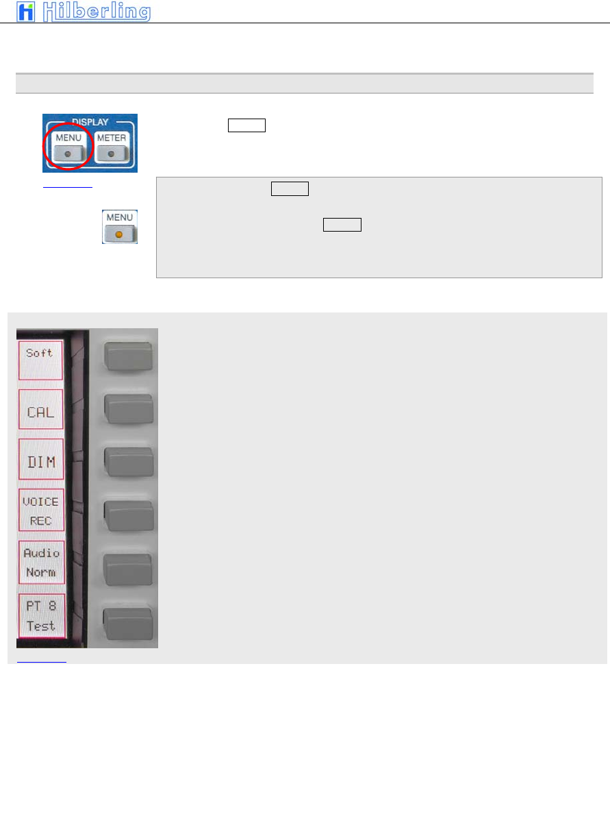
PT-8000
A
·
B
·
C User Manual C–55
MENU menu
Picture 76
18 C
ALIBRATION
,
V
OICE
R
ECORDER
The button MENU located in the cluster DISPLAY provides access to various
settings and calibration routines of the PT-8000, to the spectrum display
(band scope and channel scope) and the voice recorder.
Pushing the button MENU
• MENU-LED will be on
• MENU Softkey menu will be called up
Display software version RX CPU and access to update software
Internal reference and preselector
Brightness of display
Voice recorder (recording functions)
The key toggles between Audio Norm/Split (see below)
Various test functions may be activated TBD
Audio Normal will feed audio from MAIN and SUB to both speakers (PT-8000
and HN-8000). The volume of both RX is controlled by the appropriate knobs
MAIN and SUB.
Pushing MAIN or SUB in Audio Normal will turn off PT-8000 speaker (MAIN)
or HN-8000 speaker (SUB)
Audio Split will separate audio from MAIN and SUB hence MAIN is fed to
PT-8000 speaker and SUB to HN-8000 speaker.
Picture 75
Audio-Norm
Audio-Split
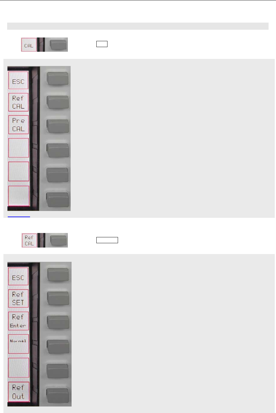
C–56 Part C Installation And Operation
CAL menu
Ref CAL menu
Pi t 78
18.1 Reference Calibration And Preselector Calibration
Pushing CAL softkey will call up Calibration menu:
Return to MENU menu
Call Ref CAL menu (internal reference)
Call Pre CAL menu (alibration routine for preselector)
18.1.1 Reference Calibration
Pushing Ref CAL softkey will call up Reference Calibration menu:
Return to CAL menu
Activate entry of correction value for reference oscillator through VFO
MAIN/REF-SET control. Values are –16106 to +16106
Store the correction value
Set correction value back to zero
Picture 77
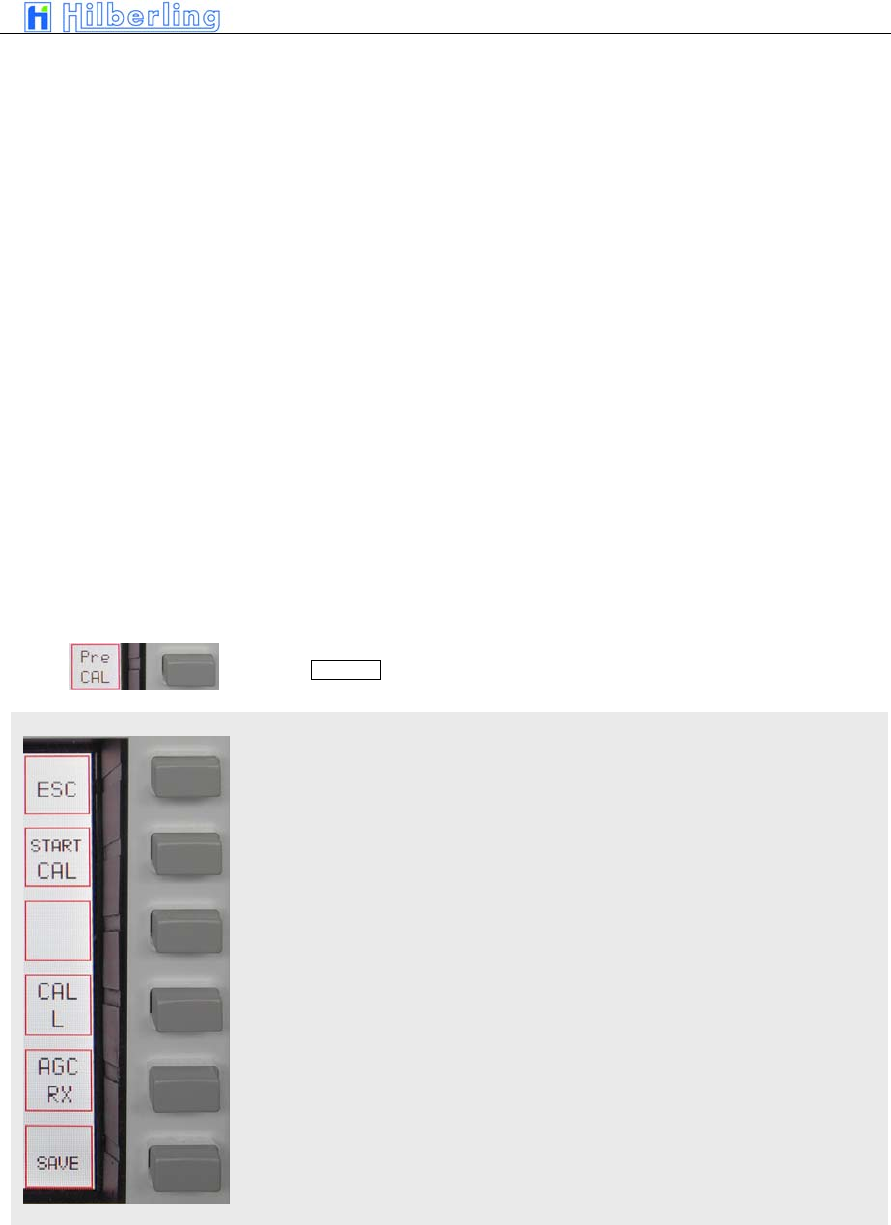
PT-8000
A
·
B
·
C User Manual C–57
Pre CAL menu
Pi t 80
Toggle reference output ON / OFF
The display will change to a blue screen
(TBD)
18.1.2 Preselector Calibration
Pushing Pre CAL softkey will call up Preselector Calibration menu:
Return to the CAL menu
Start calibration routine
Call CAL L menu (adjust inductors of preselector manually)
TBD
TBD
Pi t 79 (TBD)
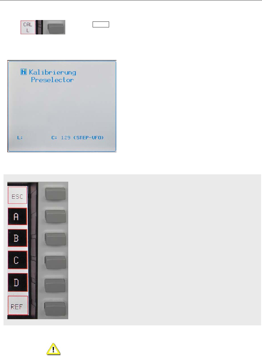
C–58 Part C Installation And Operation
CAL L menu
Pi t 82
Pushing CAL L softkey will call up a menu which allows to calibrate the
preselector manually by tuning the L component. Segments of the main
inductor may be added by activating A/B/C/D simultaneously:
The display will change
The alignment of the preselector can be done
manually. Both C and L may be tuned. This function is
preliminary – it will only work on the actual frequency
tuned – i.e. there is no storage of data yet.
To align use a signal received on the tuned frequency
or by means of a signal generator.
The capacitors of the preselector may be manually
tuned by rotating the STEP-VFO control. Tuning range
is between 1 and 255.
Tuning the Cs is possible without activating a software
menu – unlike tuning L (see below).
Return to the Pre CAL menu
Select part A of main inductor
Select part B of main inductor
Select part C of main inductor
Select part D of main inductor
TBD
Tuning of preselector is normally not necessary – the alignment has been
done in the factory. However if done one should bear in mind preselector
calibration will take around 30 minutes. No HF antenna should be attached to
the unit during calibration.
Pi t 81
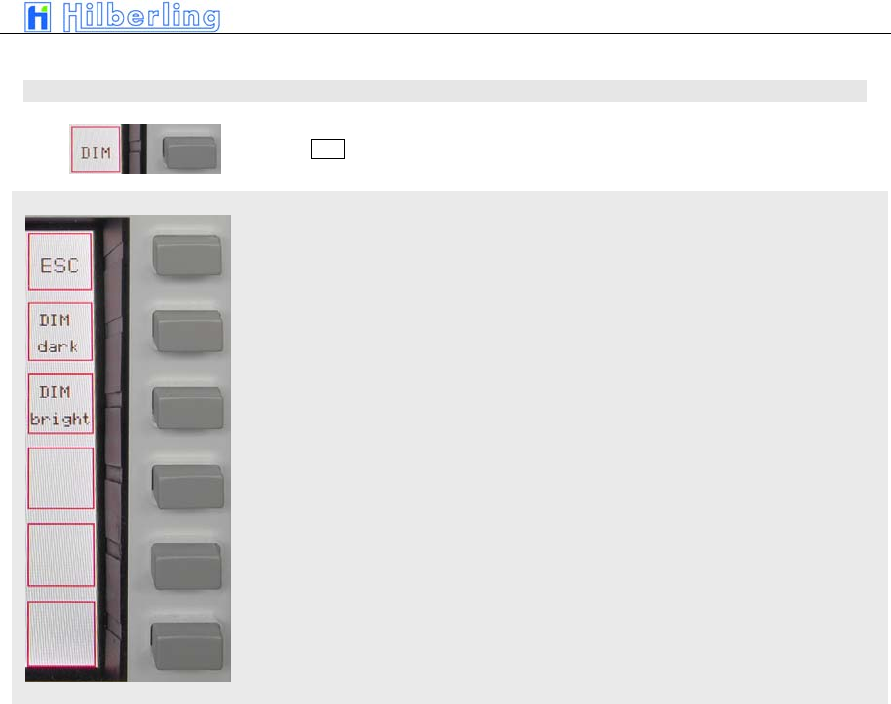
PT-8000
A
·
B
·
C User Manual C–59
DIM menu
18.2 Brightness Display (DIM)
Pushing DIM softkey will call up DIM menu:
Return to the MENU menu
Pushing repeatedly will dim the display
Pushing repeatedly will increase background light of display
Pi t 83
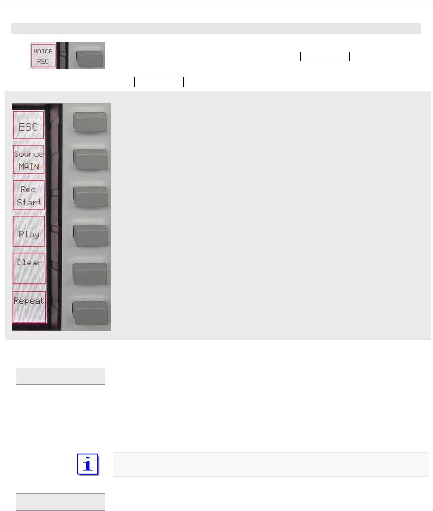
C–60 Part C Installation And Operation
VOICE REC menu
18.3 Recording Functions (Voice Recorder)
Activation of voice recorder by pushing softkey VOICE REC:
The VOICE REC softkey menu will be called up:
Leave VOICE REC submenu and get to MENU
Select source for recording in a sequential order: MAIN-RX; SUB-RX; TX –
the respective sources will be displayed
Start and Stop of recording (toggle mode); Start and Stop will be displayed
accordingly
Play and Stop playing (toggle mode); Play and Stop will be displayed
accordingly
Clear recording memory; all records are deleted
Loop all recordings
• If the last recording is not deleted the actual
recording will be added
• In case the memory has reached its capacity the
recording will be ceased. Rec Start will be
displayed. However a new record in not possible
until the memory has been cleared.
The memory has a capacity to record 120 seconds
• Playback will always start at the very beginning
of the records
If the records are to be transmitted simply key the TX
• When playback is finished (end of record or
Stop) Play softkey is displayed.
Pi t 84
Recording
Playback
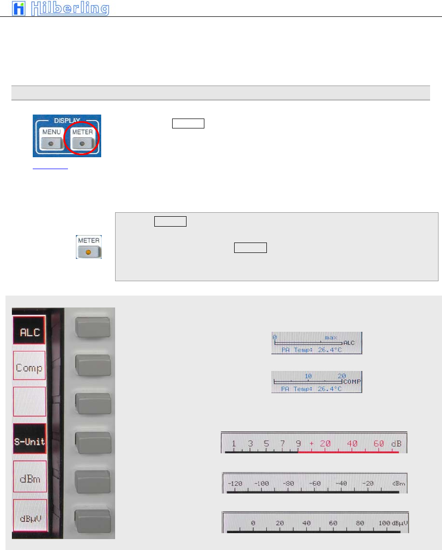
PT-8000
A
·
B
·
C User Manual C–61
METER menu
• The loop function may be activated during
playback; the record will be repeated endless
until Stop is activated
19
M
ETERING
O
F
PT-8000
(METER)
The button METER located in the cluster DISPLAY allows to change the
units displayed for the S.Meter (active RX):
Hams radio units S + dB, dBm or dBµV.
The meaning of the smaller right hand scale may also be altered from ALC
and Compression level.
Pushing METER will:
• METER-LED will be on
• The METER softkey-menu will be called up
ALC (Automatic Level Control) from TX will be displayed
Compression level from TX will be displayed
S-Meter indicates ham
radio standard: S + dB
S-Meter indicates: dBm
S-Meter indicates: dBµV
Picture 85
Pi t 86
Pi t 87
Pi t 88
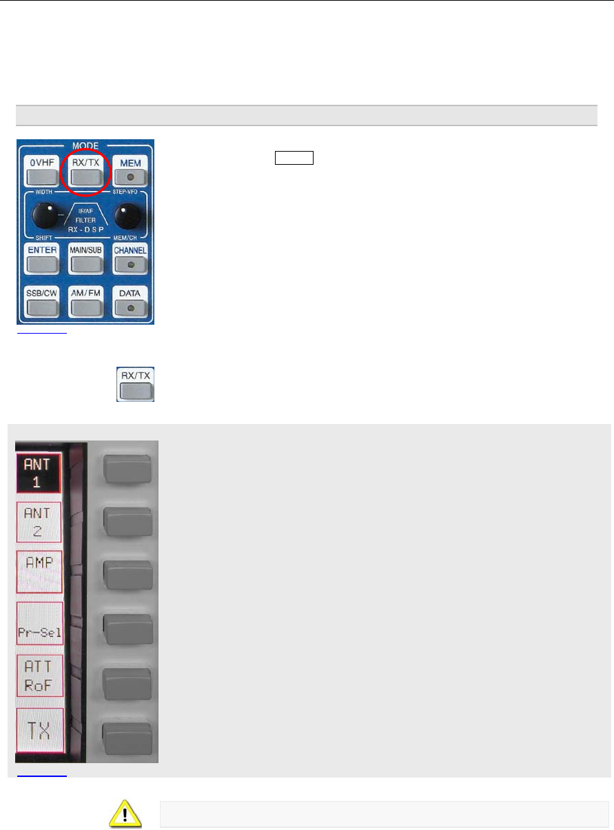
C–62 Part C Installation And Operation
RX menu HF
Picture 90
20
B
ASIC
S
ETTINGS
RX/TX
Pushing the button RX/TX located in the cluster MODE will call up two types
of menus which gives access to various basic settings for RX and TX.
If the last used menus (TX or RX) will be called up.
Depending on whether HF or VHF is selected the menus and display
described below may vary.
RX menu HF
Select antenna #1 or – second press – antenna #1 for TX and an additional
RX antenna. Softkey will be shown invers. The Display will show ANT 1 or
ANT 1 RX if appropriate.
Select antenna #2 – softkey will be shown invers. The Display will show ANT
2 if appropriate.
Preamplifier may be switches ON, ON + 7kHz HPF and ON + 14kHz HPF.
Softkey will be shown invers. The Display will show blank, AMP, AMP 7+ or
AMP 14+
Preselector may be switches ON or OFF. Softkey will be shown invers. The
Display will show Preselect in the status field if appropriate.
This softkey will give access to a sub menu to select different roofing filters
and to activate the attenuator
Access to TX menu
When working VHF preselector is not available (see below).
Picture 89
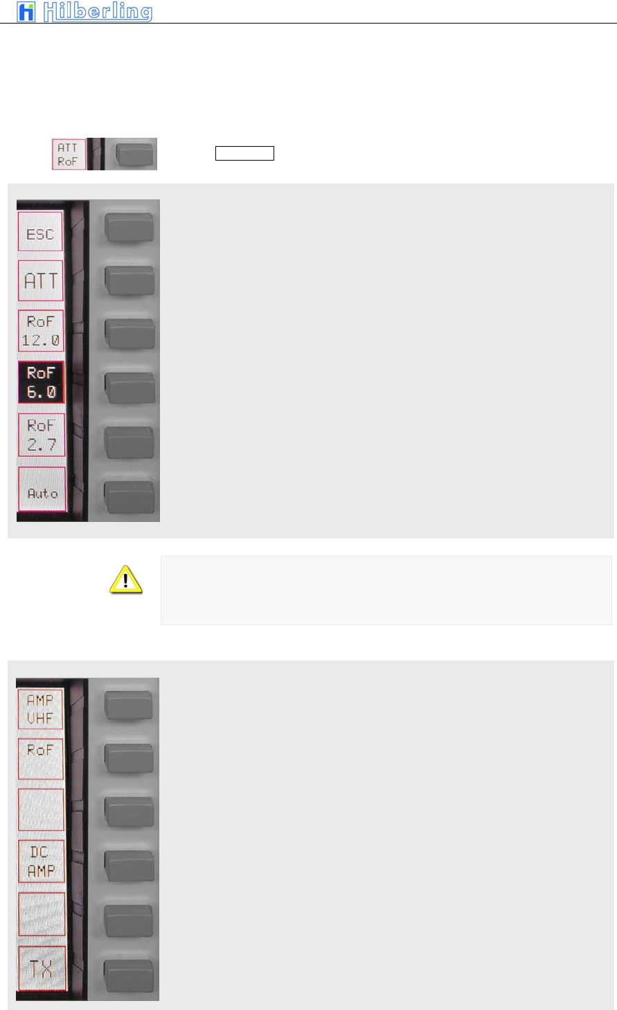
PT-8000
A
·
B
·
C User Manual C–63
ATT / RoF menu HF
RX menu VHF
Pushing ATT / RoF softkey will call up ATT/RoF menu HF
Pushing ESC will return to the RX menu
Activate 6dB Attenuator
Select Roofing Filter 12.0 kHz
Select Roofing Filter 6.0 kHz
Select Roofing Filter 2.7 kHz
Switch back to normal i.e. automatic selection of roofing filters
If the Noise Blanker is activated the 12 kHz roofing filter will always be
selected
If MODE is changed the selection will be normal, i.e. automatic. Same is true
for power ON condition.
RX menu VHF
This softkey will give access to a sub menu to select different roofing filters
When activating this function 12 Volt DC are fed to the coaxial cable in order
to run remote switches or remotely operated amplifiers through this supply
voltage. The current is rated to 1 Amps.
Pi t 91
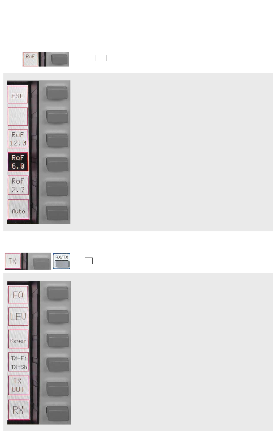
C–64 Part C Installation And Operation
RoF menu VHF
TX menu
Access to TX menu
Pushing RoF softkey will call up RoF menu VHF
Pushing ESC will return to the RX menu
Select Roofing Filter 12.0 kHz
Select Roofing Filter 6.0 kHz
Select Roofing Filter 2.7 kHz
Switch back to normal i.e. automatic selection of roofing filters
The TX softkey menu offers the following functions:
Access to 3 band EQUALIZER menu for TX to enhance audio as desired.
Toggle Leveler ON/OFF
Access to KEYER menu
Access to TX-Filter / TX-Shift menu
Toggle built-in automatic (iambic) CW-keyer ON/OFF
Pi t 93
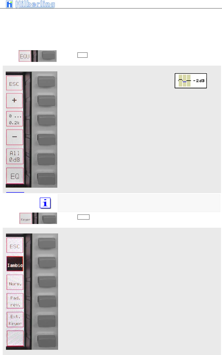
PT-8000
A
·
B
·
C User Manual C–65
EQUALIZER menu
KEYER menu
Access to TX Out menu
Access to RX menu
Pushing EQU softkey will call up the EQUALIZER menu:
Back to TX menu
Increase gain of selected EQU-band in 1dB Steps. Maximum gain is +9dB
Select EQU-band in a cyclic manner. EQU-band is depicted on the display
Decrease gain of selected EQU-band in 1dB Steps. Maximum gain is -9dB
Reset all previous settings to 0 dB for all 3 EQU-bands
Toggle Equalizer ON / OFF
The EQU-bands are defined:
0 ... 200 Hz / 200 ... 1500 Hz / 1500 ... 3000Hz
Pushing Keyer softkey will call up the KEYER menu:
Back to TX menu
Selects “iambic” mode of the internal keyer
Selects “normal” mode of internal keyer
Reverses paddle function to accommodate left-/right hand operation
Pi t 94
Picture 95
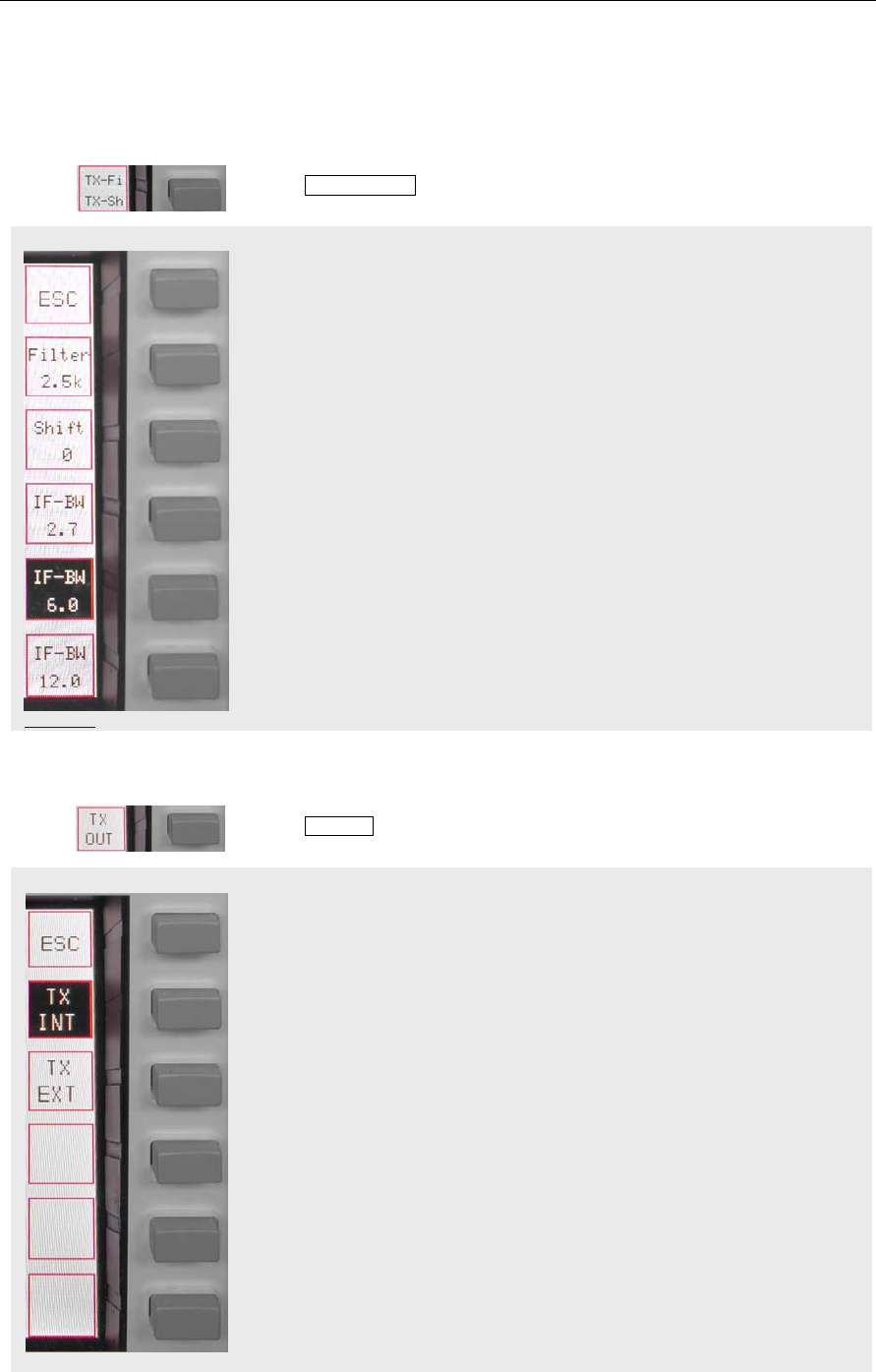
C–66 Part C Installation And Operation
TX-Filter / TX-Shift menu
Picture 97
TX-OUT menu
Shuts off internal keyer to allow use of external keying device
Pushing TX-Fi / TX-Sh softkey will call up the TX-Filter / TX-Shift menu:
Return to TX menu
Press and hold while turning STEP-VFO control to select filter bandwidths
between 2.5 kHz and 3.4 kHz
Press and hold while turning STEP-VFO control to adjust TX filter shift (TX-
passband) from 0 Hz to +300 Hz in 25 Hz increments
Select 2.7 kHz 70.7 MHz bandwidth
Select 6.0 kHz 70.7 MHz bandwidth
Select 12 kHz 70.7 MHz bandwidth
Pushing TX-OUT softkey will call up TX OUT menu
Return to TX menu
TX-signal will be routed to internal power amplifier
TX-signal will be routed to J14 (BNC; +20dBm) at rear panel to drive external
equipment. Internal power amplifier will be shut down.
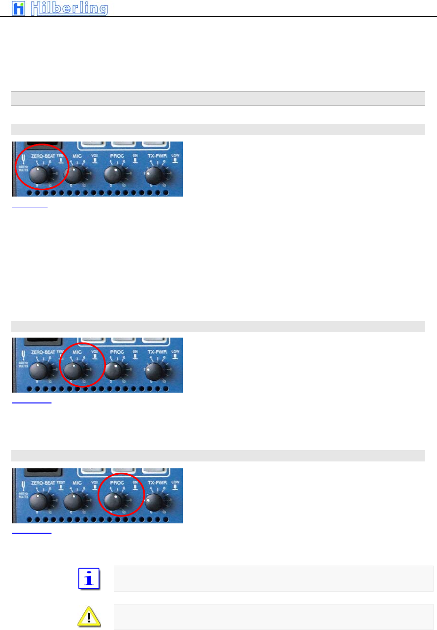
PT-8000
A
·
B
·
C User Manual C–67
21 T
RANSMITTER
C
ONTROLS
Various controls for transmitter settings are located on the front panel as depicted.
21.1 ZERO-BEAT
Pushing ZERO-BEAT control will activate a 440 Hz tone
in RX and TX mode.
In TX mode a 440 Hz tone will be transmitted.
In RX the tone can be heard in both RX. The volume might be adjusted by
turning the knob.
Given both transmitting and receiving stations can activate a 440 Hz tone an
interference might be heard in case both station vary in RX and/or TX
frequencies.
21.2 MIC
Turning MIC will adjust microphone sensitivity. Adjust
not to exceed ALC limits shown on the ALC-meter.
Pushing MIC will turn ON and OFF VOX
21.3 PROC
Pushing PROC will turn ON and OFF microphone
processor. Turning the knob will increase the processor
level. Adjust not to exceed COMP limits shown on the
COMP-meter.
If PROC is active COMP ON will be displayed
PROC is only available in USB/LSB
Picture 99
Picture 100
Picture 101
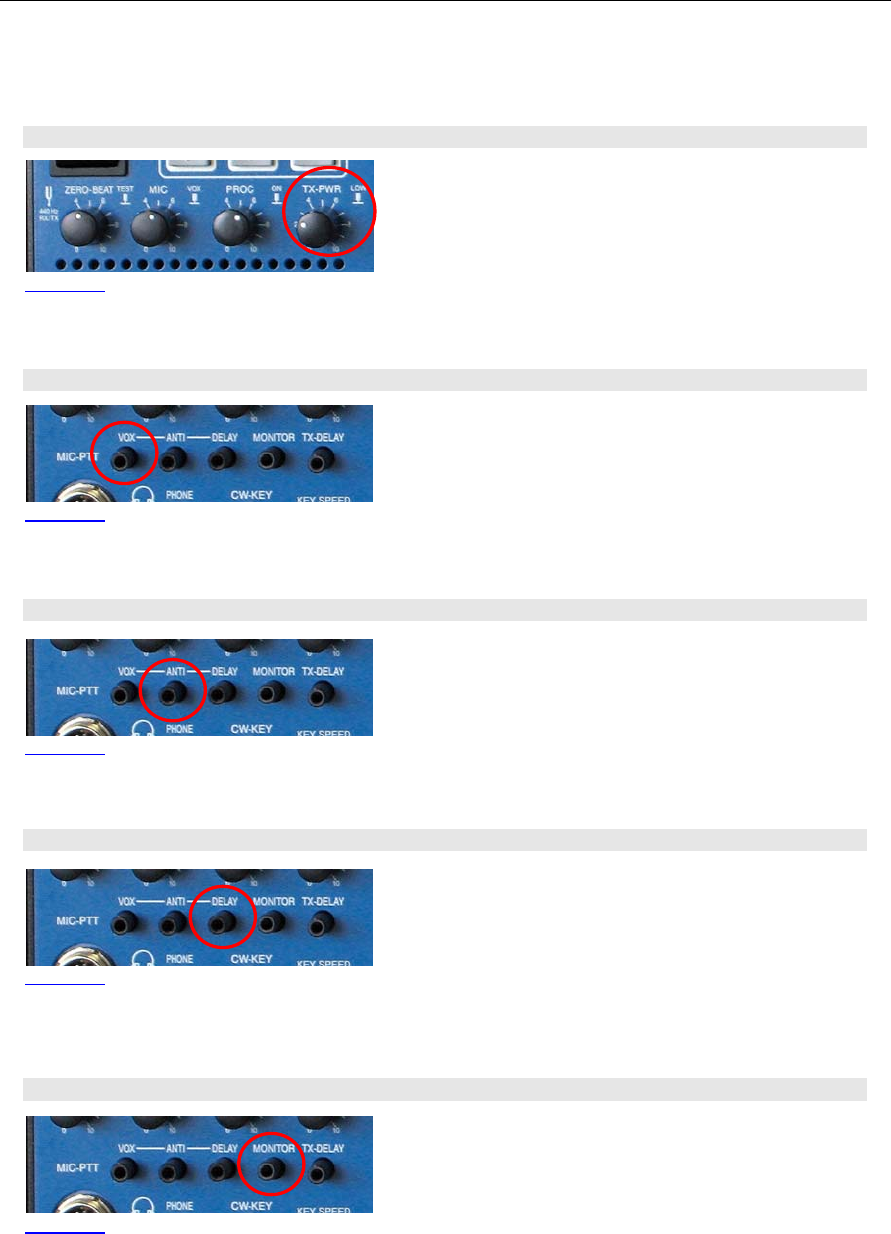
C–68 Part C Installation And Operation
21.4 TX-PWR
Pushing the TX-PWR control will toggle the transmitter
between low- and high power (10/25 Watts on HF/VHF
and 100/600Watts on HF for Model A/B). Turning the
knob allows continuous variation of power output in
these two ranges.
21.5 VOX
If VOX has been turned on this control adjusts the
trigger level for VOX activation. Adjust sensitivity to your
convenience and speech habits.
21.6 ANTI-TRIP
Signals from the speaker(s) might trigger or trip the VOX
unintentionally. ANTI-TRIP will countereffect this. Adjust
to get both reliable action and anti-trip of VOX circuit.
21.7 DELAY (of VOX)
DELAY of VOX circuit allows to adjust the hold time of
VOX activation hence to get smooth VOX operation and
to counteract any VOX switching between fluently
spoken voice.
21.8 Monitoring Function (MONITOR)
Turning the MONITOR control will adjust the volume auf
the audio to monitor the transmission of PT-8000.
Picture 102
Picture 103
Picture 104
Picture 105
Picture 106
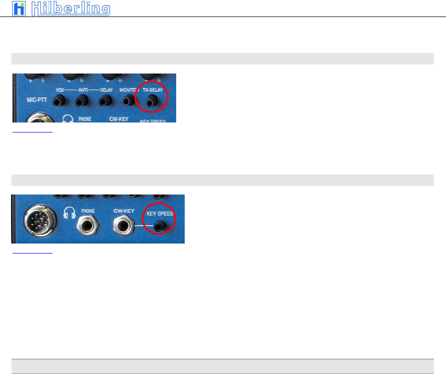
PT-8000
A
·
B
·
C User Manual C–69
21.9 TX-DELAY (CW)
Turning TX-Delay clockwise will increase the time for
transmit/receive switching (turn-around time) during CW
mode. Setting TX-Delay fully counter clockwise ensures
the shortest T/R turn-around possible – called BK (break
in).
21.10 KEY SPEED
Turning KEY SPEED controls the speed of the internal
iambic keyer between 5 and XX WPM.
The CW weight remains constant.
22 O
PERATING
A
UXILIARY
E
QUIPMENT
TBD
Picture 107
Picture 108

C–70 Part C Installation And Operation
Part D Annex
23
S
OFTWARE
U
PDATE
TBD

PT-8000
A
·
B
·
C User Manual C–71
–– This page is intentionally blank ––

C–72 Part C Installation And Operation