Hill Phoenix Onrb Users Manual Orb
ORB to the manual 4d13b5bd-dc8b-4b73-a37d-017305c636d9
2015-02-09
: Hill-Phoenix Hill-Phoenix-Onrb-Users-Manual-565193 hill-phoenix-onrb-users-manual-565193 hill-phoenix pdf
Open the PDF directly: View PDF ![]() .
.
Page Count: 44

HANDBOOK
INSTALLATION & OPERATION
REACH-IN
BEVERAGE
CASES
P057333G
Rev. 12 6/06
MODEL: ORB, ORBH,
ONRB & ONRBH
COMPONENT

Welcome to the ORIGIN2display case family. We’re very pleased you
joined us.
This installation and operation handbook has been especially
prepared for everyone involved with ORIGIN2display cases – owners,
managers, installers and maintenance personnel.
You’ll find this book different than traditional manuals. The most
dramatic difference is the use of many more illustrated instructions to
make it easier to read and to help you get the most from this innovative
new design. When you follow the instructions you should expect
remarkable performance, attractive fits and finish, and long case life.
We are interested in your suggestions for improvement both in case
design and in this handbook. Please call/write to:
Hill PHOENIX
Marketing Services Department
1925 Ruffin Mill Rd.
Colonial Heights, VA 23834
Tel: 804-526-4455
Fax: 804-526-7450
or visit our web site at
www.hillphoenix.com
We wish you the very best in outstanding food merchandising and a
long trouble-free operation.

1
TABLE OF CONTENTS
GENERAL INFORMATION – PAGES 3 - 8
General information, first step recommendations and case dimensional drawings.
THE USE OF CASTERS – PAGE 9
Cases roll on casters–general use and caster removal.
LINE-UP – PAGES 10 - 11
A twelve step procedure for initial case lineup with illustrations.
TRIM-OUT – PAGES 12 - 13
A fifteen step procedure for trimming out cases with illustrations.
REFRIGERATION PIPING – PAGE 14
Diagrams show coil outlet, case controls location, and other piping tips.
PLUMBING – PAGE 15
Information on drain connections.
ELECTRICAL HOOKUP AND WIRING DIAGRAMS – PAGES 16 - 25
Complete information on electrical connections.
CONTROL SETTING GUIDELINE – PAGES 26 - 29
Recommended settings for all case controls.
DEFROST AND TEMPERATURE CONTROL – PAGE 30
Defrost data - electric and hot gas defrost. Sensor bulb locations.
PRODUCT LOADING – PAGE 31
Air flow and load limits.
USE AND MAINTENANCE – PAGES 32 - 33
Cleaning and fan information.
PARTS ORDERING – PAGES 34 - 36
Replacement parts identification.
APPENDIX A - PAGE 37
NOTES - PAGE 38
PRODUCT WARRANTY - Inside Back Cover

2

3
GENERAL INFORMATION
DESCRIPTION OF CASES: The refrigerated display cases described in this handbook
are part of the Hill PHOENIX, Origin2design series. Specifically covered in this manual are
models ORB reach-in beverage, ORBH high reach-in beverage, ONRB narrow reach-in bev-
erage, & ONRBH high narrow reach-in beverage.
STORE CONDITIONS: Hill PHOENIX cases are designed to operate in an air conditioned
store with a system that can maintain 75OF (24OC) store temperature and 55 percent (maxi-
mum) relative humidity (CRMA conditions). Case operation will be adversely affected by
exposure to excessively high ambient temperatures and/or humidity.
REFRIGERATION SYSTEM OPERATION: Air cooled condensing units require ventilation for
efficient performance of condensers. Machine room temperatures must be a minimum of
65OF in winter and a maximum of 95OF in summer. Minimum condensing temperatures
should be no less than 70OF.
RECEIVING CASES: Examine fixtures carefully for shipping damage and shortages. For
information on shortages contact the Service Parts Department at 1-800-283-1109.
APPARENT DAMAGE: A claim for obvious damage must be noted on the freight bill or
express receipt and signed by the carriers agent, otherwise the carrier may refuse the claim.
CONCEALED DAMAGE: If damage is not apparent until after the equipment is unpacked,
retain all packing materials and submit a written request to the carrier for inspection within
15 days of receipt of equipment.
LOST ITEMS: This equipment has been carefully inspected to insure the highest level of
quality. Any claim for lost items must be made to Hill PHOENIX within 48 hours of receipt
of equipment.
TECHNICAL SUPPORT: If any technical questions arise regarding a refrigerated display
case contact our Customer Service Department in Richmond at 1-804-526-4455. For any
questions regarding our refrigeration systems or electrical distribution centers contact our
Customer Service Department in Conyers at 1-770-285-3200.
CONTACTING FACTORY: Should you need to contact Hill PHOENIX regarding a specific
fixture, be sure to know the case model number and serial number. This information is on
the serial plate located on the top flue panel of the case (see next page for details). Ask for
a Service Parts Representative at 1-804-526-4455.
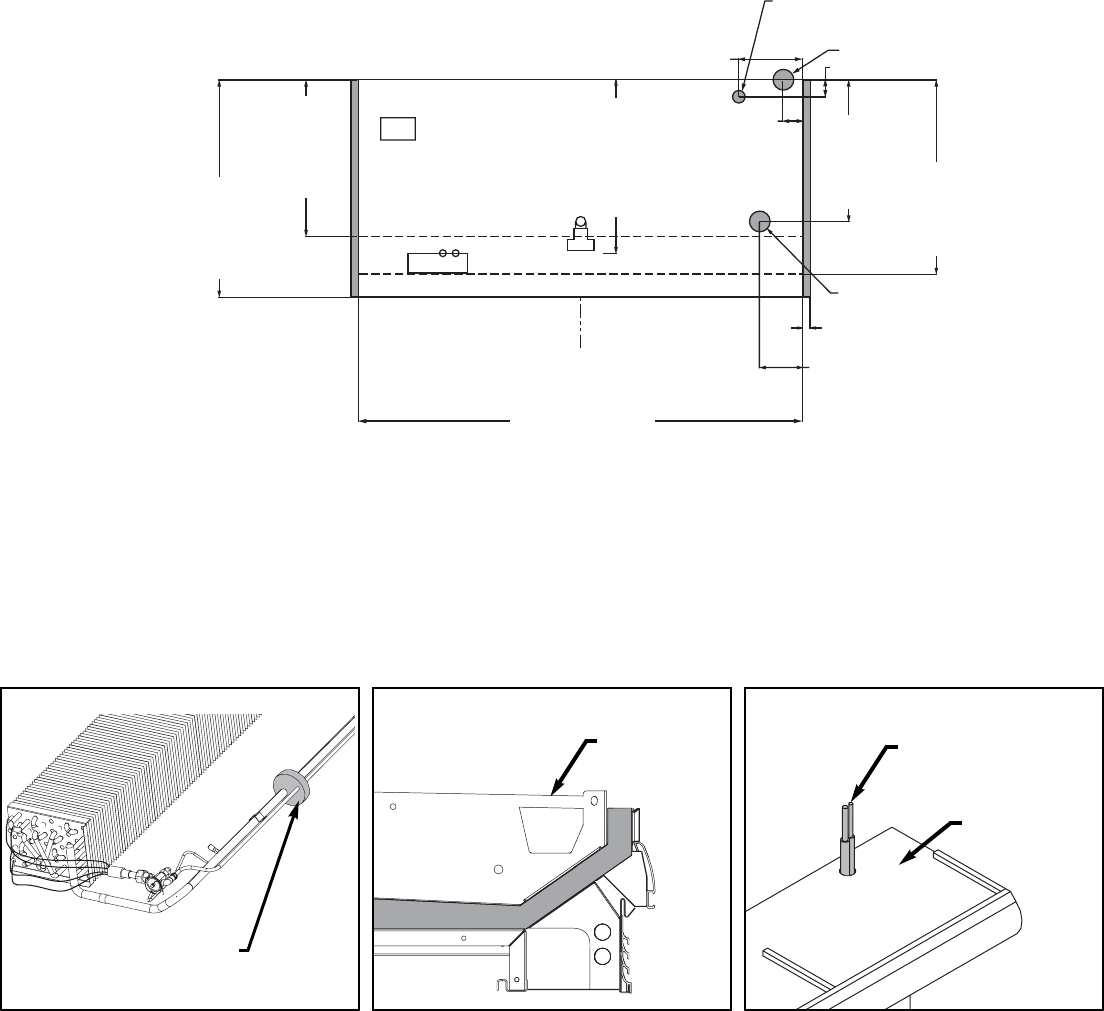
4
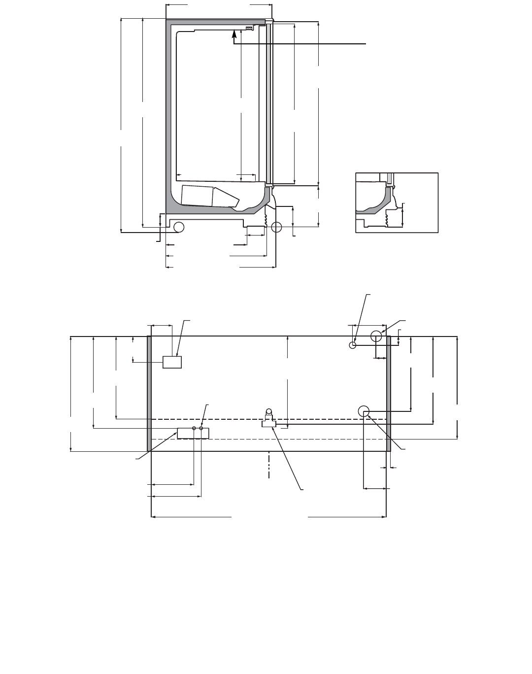
41 7/16 in [105.2 cm]
81 1/4 in
[206.3 cm]
83 1/4 in
[211.5 cm]
6 13/16 in [17.2 cm]*
42 11/16 in [108.4 cm]
COIL PLENUM
30 7/8 in [78.4 cm]
59 in
[149.9 cm] 62 3/8 in
[158.4 cm]
(Door Height)
64 in
[162.6 cm]
(Frame Height)
C
L
34 11/16 in
[88.1 cm]
31 9/16 in
[80.2 cm]
10 in
[25.4 cm]
JUNCTION BOX
(STANDARD)
8 in [20.3 cm]
WIRING-TO-TOP
(OPTIONAL)
35 1/8 in
[89.2 cm]
**
1 1/2" PVC DRAIN
CONNECTION
28 5/8 in
[72.7 cm]
33 9/16 in
[85.3 cm]
39 1/4 in
[99.7 cm]
REFRIGERATION
1 1/2 in
[3.8 cm]
{END}
8 11/16 in [22.1 cm]
FRONT OF CASE
5 1/8 in
[13.1 cm]
16 1/16 in
[40.9 cm]
8 1/2 in
[21.6 cm]
31 9/16 in [80.2 cm]
39 1/4 in [99.7 cm]
NOTES:
* STUB-UP AREA
** RECOMMENDED STUB-UP CENTERLINE FOR ELECTRICAL AND HUB DRAINS
z ENDS ADD APPROXIMATELY 1 INCH TO CASE HEIGHT
z WIRING-TO-THE-TOP- ADDS APPROXIMATELY 1 INCH TO CASE HEIGHT
z A 2" MINIMUM AIR GAP IS REQUIRED BETWEEN THE REAR OF THE CASE AND A WALL
z SUCTION LINE (ALL LENGTHS) 1/2"
z LIQUID LINE (ALL LENGTHS) - 3/8", LIQUID LINE w/ HOT GAS DEFROST (ALL LENGTHS) - 1/2"
z AVAILABLE SHELF SIZES: WIRE SHELVES 16", 18", 20", 22" & 23 1/2"
SOLID SHELVES 18", 20", 22", 24" & 27"
(TOP SHELF MUST BE 24" OR SHORTER WHEN USING 27" SHELVES.
RECOMMENDED CONFIGURATION IS 1 - 24" SHELF AND 4 - 27" SHELVES BELOW
TOP SHELF)
60 in [152.4 cm] {2 Door}
90 in [228.6 cm] {3 Door}
120 in [304.8 cm] {4 Door}
150 in [381.0 cm] {5 Door}
180 in [457.2 cm] {6 Door}
4 in [10.2 cm]
PIPING-TO-TOP
(OPTIONAL)
12 3/4 in [32.4 cm] 3 3/8 in [8.6 cm]
REAR REFRIGERATION
(13 15/16" off of floor)
42 11/16 in
[108.4 cm]
7 1/2 in
[19.1 cm]
1/2 BUMPER OPTION
ELECTRICAL
16 1/16 in [40.8 cm]
18 9/16 in [47.1 cm]
Amp plate &
Serial Plate
location
MODEL
ORB
GENERAL INFORMATION
5
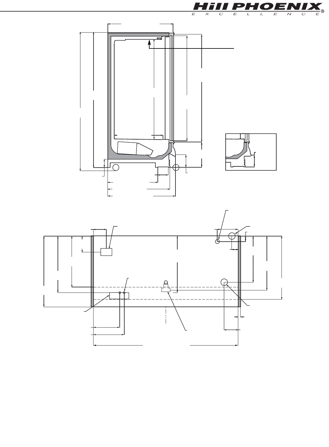
NOTES:
* STUB-UP AREA
** RECOMMENDED STUB-UP CENTERLINE FOR ELECTRICAL AND HUB DRAINS
z ENDS ADD APPROXIMATELY 1 INCH TO CASE HEIGHT
z WIRING-TO-THE-TOP- ADDS APPROXIMATELY 1 INCH TO CASE HEIGHT
z A 2" MINIMUM AIR GAP IS REQUIRED BETWEEN THE REAR OF THE CASE AND A WALL
z SUCTION LINE (ALL LENGTHS) 1/2"
z LIQUID LINE (ALL LENGTHS) - 3/8", LIQUID LINE w/ HOT GAS DEFROST (ALL LENGTHS) - 1/2"
z AVAILABLE SHELF SIZES: WIRE SHELVES 16", 18", 20", 22" & 23 1/2"
SOLID SHELVES 18", 20", 22", 24" & 27"
(TOP SHELF MUST BE 24" OR SHORTER WHEN USING 27" SHELVES.
RECOMMENDED CONFIGURATION IS 1 - 24" SHELF AND 4 - 27" SHELVES BELOW
TOP SHELF)
7 1/2 in
[19.1 cm]
1/2 BUMPER OPTION
41 7/16 in [105.2 cm]
6 13/16 in [17.2 cm]*
42 11/16 in [108.4 cm]
COIL PLENUM
30 7/8 in [78.4 cm]
5 1/8 in
[13.1 cm]
16 1/16 in
[40.9 cm]
8 1/2 in
[21.6 cm]
31 9/16 in [80.2 cm]
39 1/4 in [99.7 cm]
85 1/16 in
[216.0 cm]
87 1/16 in
[221.1 cm]
63 in
[160.1 cm] 66 3/8 in
[168.6 cm]
(Door Height)
68 in
[172.7 cm]
(Frame Height)
C
L
34 11/16 in
[88.1 cm]
31 9/16 in
[80.2 cm]
10 in
[25.4 cm]
JUNCTION BOX
(STANDARD)
8 in [20.3 cm]
WIRING-TO-TOP
(OPTIONAL)
35 1/8 in
[89.2 cm]
**
1 1/2" PVC DRAIN
CONNECTION
28 5/8 in
[72.7 cm]
33 9/16 in
[85.3 cm]
39 1/4 in
[99.7 cm]
REFRIGERATION
1 1/2 in
[3.8 cm]
{END}
8 11/16 in [22.1 cm]
FRONT OF CASE
4 in [10.2 cm]
PIPING-TO-TOP
(OPTIONAL)
12 3/4 in [32.4 cm] 3 3/8 in [8.6 cm]
REAR REFRIGERATION
(13 15/16" off of floor)
42 11/16 in
[108.4 cm]
60 in [152.4 cm] {2 Door}
90 in [228.6 cm] {3 Door}
120 in [304.8 cm] {4 Door}
150 in [381.0 cm] {5 Door}
180 in [457.2 cm] {6 Door}
96 in [243.8 cm] {8' case}
144 in [365.8 cm] {12' case}
ELECTRICAL
16 1/16 in [40.8 cm]
18 9/16 in [47.1 cm]
MODEL
ORBH
Amp plate &
Serial Plate
location
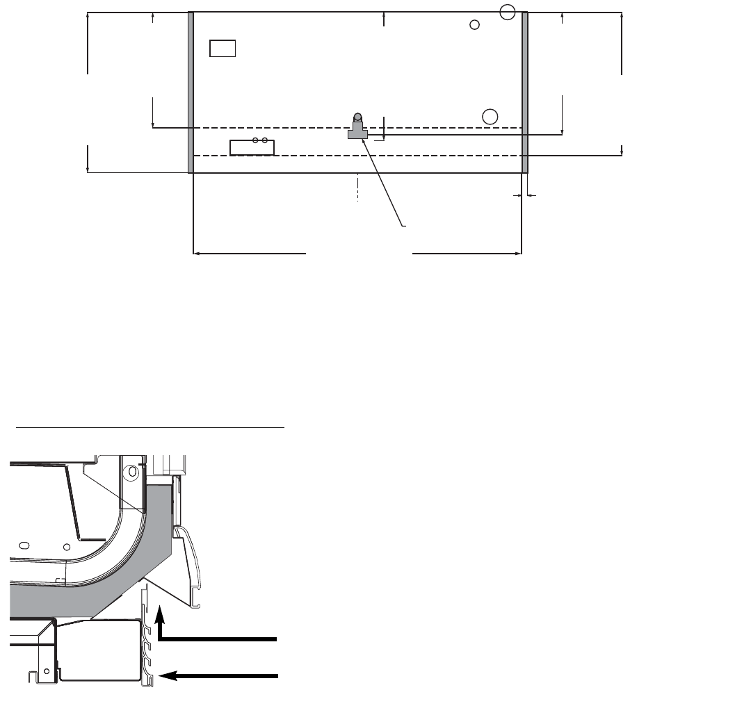
6
C
L
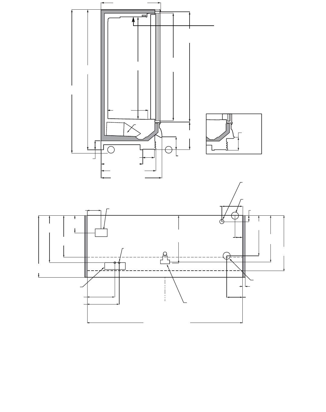
NOTES:
* STUB-UP AREA
** RECOMMENDED STUB-UP CENTERLINE FOR ELECTRICAL AND HUB DRAINS
z ENDS ADD APPROXIMATELY 1 INCH TO CASE HEIGHT
z WIRING-TO-THE-TOP- ADDS APPROXIMATELY 1 INCH TO CASE HEIGHT
z A 2" MINIMUM AIR GAP IS REQUIRED BETWEEN THE REAR OF THE CASE AND A WALL
z SUCTION LINE (ALL LENGTHS) 1/2"
z LIQUID LINE (ALL LENGTHS) - 3/8", LIQUID LINE w/ HOT GAS DEFROST (ALL LENGTHS) - 1/2"
z AVAILABLE SHELF SIZES: WIRE SHELVES 16", 18", 20" & 22"
SOLID SHELVES 18", 20" & 22"
(TOP SHELF MUST BE 20" OR SHORTER. RECOMMENDED CONFIGURATION IS 20"
SHELF AND 4 22" SHELVES BELOW TOP SHELF)
JUNCTION BOX
(STANDARD)
WIRING-TO-TOP
(OPTIONAL)
ELECTRICAL
1 1/2" PVC DRAIN
CONNECTION
REFRIGERATION
FRONT OF CASE
10 in
[25.4 cm]
8 in [20.3 cm]
16 1/16 in [40.8 cm]
18 9/16 in [47.1 cm]
27 9/16 in
[70.0 cm]
**
23 1/4 in
[59.1 cm]
26 7/8 in
[68.3 cm]
1 1/2 in [3.8 cm]
{END}
8 11/16 in [22.1 cm]
COIL
PLENUM
23 1/4 in
[59.1 cm]
6 13/16 in [17.3 cm]*
24 3/16 in
[61.4 cm]
31 7/8 in
[81.0 cm]
35 3/8 in [89.8 cm]
5 1/8 in
[13.1 cm]
16 1/4 in
[41.3 cm]
8 in
[20.3 cm]
64 in
[162.6 cm]
(Frame Height)
62 3/8 in
[158.4 cm]
(Door Height)
59 in
[149.9 cm]
24 3/16 in [61.4 cm]
31 7/8 in [81.0 cm]
27 5/16 in
[69.4 cm]
REAR REFRIGERATION
(12 1/4" off of floor)
4 in
[10.2 cm]
PIPING-TO-TOP
(OPTIONAL)
3 3/8 in [8.6 cm]
12 3/4 in [32.4 cm]
60 in [152.4 cm] {2 Door}
90 in [228.6 cm] {3 Door}
120 in [304.8 cm] {4 Door}
150 in [381.0 cm] {5 Door}
81 1/4 in
[206.4 cm]
83 1/4 in
[211.5 cm]
34 5/8 in [88.0 cm]
7 1/2 in
[19.1 cm]
1/2 BUMPER OPTION
35 3/8 in
[89.8 cm]
MODEL
ONRB
Amp plate &
Serial Plate
location
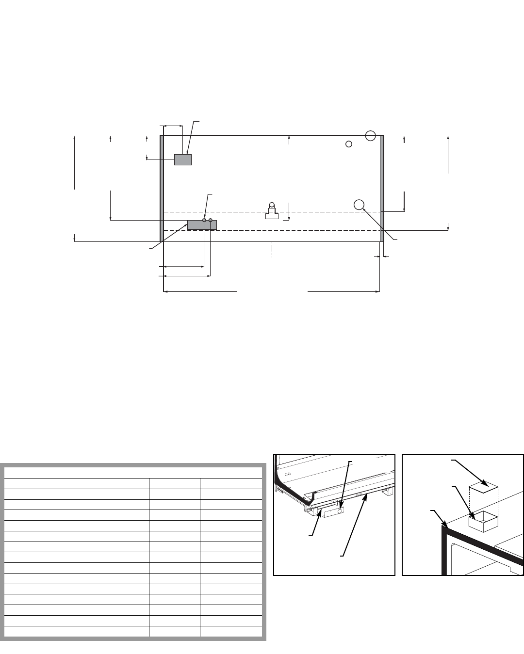
GENERAL INFORMATION
7
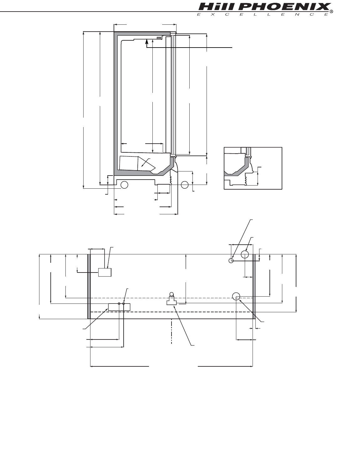
NOTES:
* STUB-UP AREA
** RECOMMENDED STUB-UP CENTERLINE FOR ELECTRICAL AND HUB DRAINS
z ENDS ADD APPROXIMATELY 1 INCH TO CASE HEIGHT
z WIRING-TO-THE-TOP- ADDS APPROXIMATELY 1 INCH TO CASE HEIGHT
z A 2" MINIMUM AIR GAP IS REQUIRED BETWEEN THE REAR OF THE CASE AND A WALL
z SUCTION LINE (ALL LENGTHS) 1/2"
z LIQUID LINE (ALL LENGTHS) - 3/8", LIQUID LINE w/ HOT GAS DEFROST (ALL LENGTHS) - 1/2"
z AVAILABLE SHELF SIZES: WIRE SHELVES 16", 18", 20" & 22"
SOLID SHELVES 18", 20" & 22"
(TOP SHELF MUST BE 20" OR SHORTER. RECOMMENDED CONFIGURATION IS 20"
SHELF AND 4 22" SHELVES BELOW TOP SHELF)
PIPING-TO-TOP
(OPTIONAL)
COIL
PLENUM
23 1/4 in
[59.1 cm]
6 13/16 in [17.3 cm]*
35 3/8 in [89.8 cm]
5 1/8 in
[13.1 cm]
16 1/4 in
[41.3 cm]
8 in
[20.3 cm]
24 3/16 in [61.4 cm]
31 7/8 in [81.0 cm]
34 5/8 in [88.0 cm]
7 1/2 in
[19.1 cm]
1/2 BUMPER OPTION
87 1/16 in
[221.1 cm]
85 1/16 in
[216.0 cm]
63 in
[160.0 cm]
66 3/8 in
[168.6 cm]
(Door Height)
68 in
[172.7 cm]
(Frame Height)
C
L
JUNCTION BOX
(STANDARD)
WIRING-TO-TOP
(OPTIONAL)
1 1/2" PVC DRAIN
CONNECTION
REFRIGERATION
FRONT OF CASE
10 in
[25.4 cm]
8 in [20.3 cm]
27 9/16 in
[70.0 cm]
**
23 1/4 in
[59.1 cm]
26 7/8 in
[68.3 cm]
1 1/2 in [3.8 cm]
{END}
8 11/16 in [22.1 cm]
24 3/16 in
[61.4 cm]
31 7/8 in
[81.0 cm]
27 5/16 in
[69.4 cm]
REAR REFRIGERATION
(12 1/4" off of floor)
4 in
[10.2 cm]
3 3/8 in [8.6 cm]
12 3/4 in [32.4 cm]
60 in [152.4 cm] {2 Door}
90 in [228.6 cm] {3 Door}
120 in [304.8 cm] {4 Door}
150 in [381.0 cm] {5 Door}
35 3/8 in
[89.8 cm]
ELECTRICAL
16 1/16 in [40.8 cm]
18 9/16 in [47.1 cm]
MODEL
ONRBH
Amp plate &
Serial Plate
location
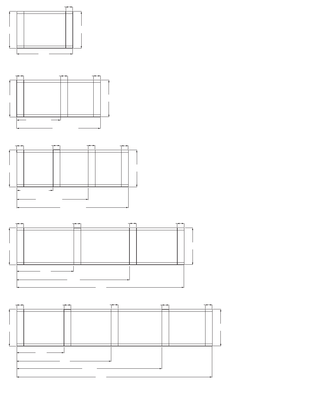
149 1/4"
97 3/16"
48 7/16"
5 DOOR CASE
FRONT OF CASE
119 1/4" (4dr CASE)
143 1/4" (12' CASE)
38 13/16" (4dr CASE)
44 5/8" (12' CASE)
4 DOOR CASE
FRONT OF CASE
77 3/16" (4dr CASE)
92 5/8" (12' CASE)
59 1/4"
4"
2 DOOR CASE
FRONT OF CASE
6"
6"
89 1/4" (3dr CASE)
95 1/4" (8' CASE)
3 DOOR CASE
8' CASE
FRONT OF CASE
47 1/2" (3dr CASE)
49 1/8" (8' CASE)
6" 4"
4"
4" 4"
4"
4" 4" 6"
23 3/16"
NARROW
31 11/16"
STANDARD
23 3/16"
NARROW
23 3/16"
NARROW
23 3/16"
NARROW
31 11/16"
STANDARD
31 11/16"
STANDARD
31 11/16"
STANDARD
179 1/4"
81 5/8"
43 3/16"
6 DOOR CASE
FRONT OF CASE
4"
4" 6" 6"
4"
23 3/16"
NARROW
31 11/16"
STANDARD
132 13/16"
8
GENERAL INFORMATION
BASEHORSE
LOCATION FOR
MODEL
ONRB, ONRBH,
ORB & ORBH
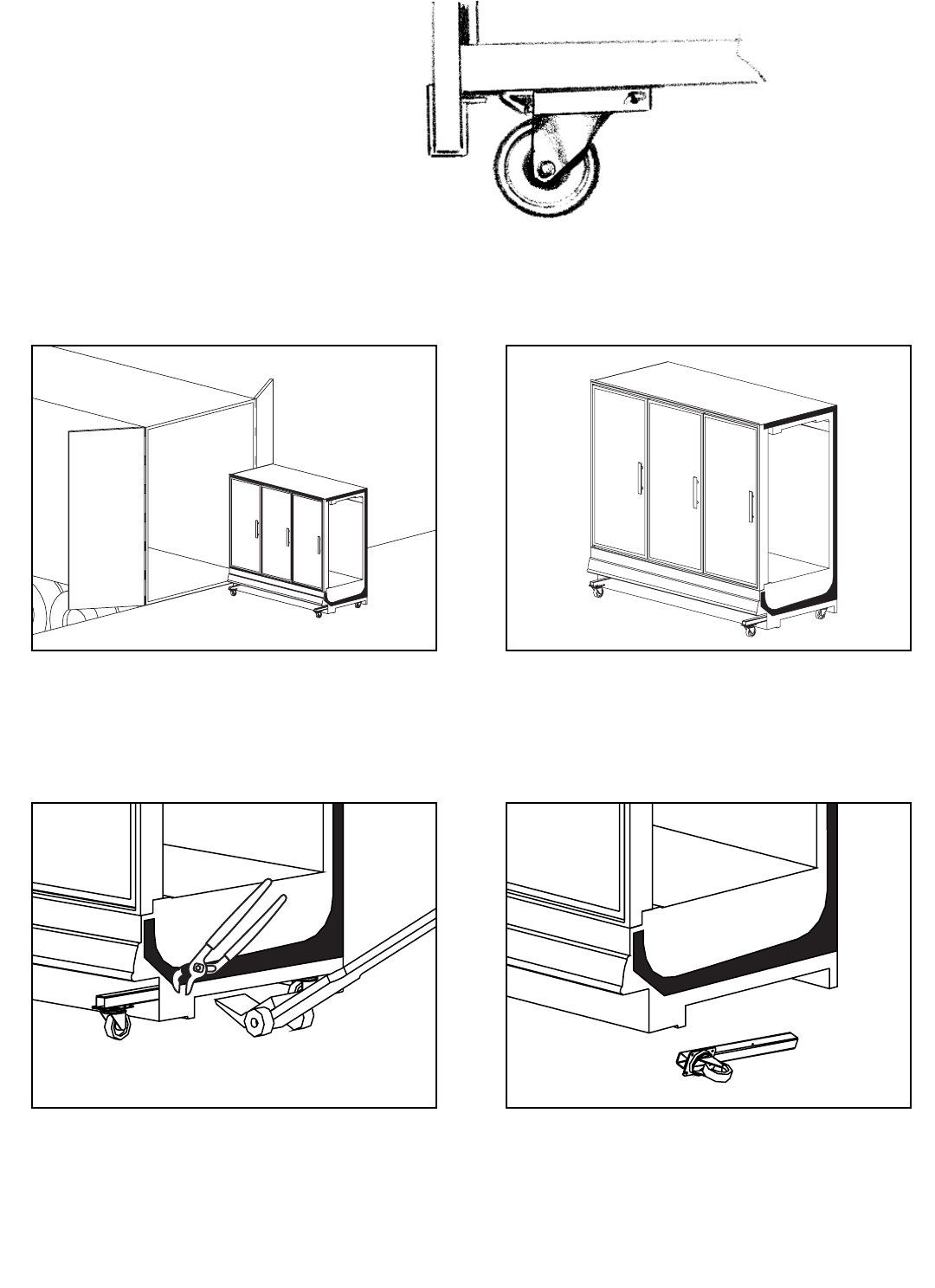
9
CASES
MOVE ON
CASTERS
FOR EASIER INSTALLATION
ORIGIN2cases are manufactured and shipped to
stores with casters installed on the base frame to
make the job of moving cases easier for everyone
involved with the manufacturing, shipping and instal-
lation process.
Casters not only speed up the process, but they also
reduce the chance of damage from raising and low-
ering cases with ”J” bar to place them on dollies,
skates or rollers. In most situations, one or two per-
sons can move the case with ease.
34
12
CASTERS MAY BE DISCARDED.
ROLL OUT OF TRUCK. When there is a truck - level
delivery dock, cases may be rolled directly from the
truck to the store floor. [CAUTION] If skid boards are
required to unload cases, casters should be removed
prior to sliding them down the skid; after which they
can be reinstalled on case.
ROLL TO LINEUP POSITION. Casters may remain in
place to move the cases to staging areas around the
store, prior to final installation. When ready for final
line-up, roll the case to set position, then remove
casters.
REMOVE COTTER PIN. Removing the casters is
easy. Simply flatten and hammer out cotter pins
then lift the case with “J” bar, and the casters will
fall off.
[CAUTION] Make certain hands are out of the way.

10
5
Set Shims On Basehorse Locations
Locate basehorse positions along
chalk lines. Spot shim packs at each
basehorse location.
LINE UP
1
Consult With General Contractor
Ask the general contractor if there
have been changes in the building
dimensions since the print you are
using was issued. Also, ask the
points of reference from which you
should take dimensions to locate the
cases. 2
Snap Chalk Lines
Mark floor where cases are to be
located for the entire lineup.
4
Level Floor. Use Laser Transit
Leveling is necessary to assure prop-
er case alignment. Locate highest
point on chalk line as reference for
determining height of shim-pack
levelers. A laser transit is recom-
mended for precision and requires
just one person.
BASE RAIL BASE RAIL
3
Snap Lines On Base Rail
Locations
Snap lines where base rails are posi-
tioned, not the front or back edges of
the cases. See case cross section
drawings, pages 4-8, for rail location
dimensions.
6
Position First Case In Lineup,
Remove Casters, Level
Roll first case into position. Raise
case from end under cross support
using “J” bar. Remove cotter pins
and casters. [CAUTION! Keep hands
from under case] Level case on
shims.
11
Ask about our case installation video available by request through your local Hill PHOENIX Sales or Field Service
Representative.
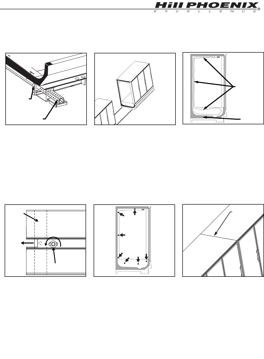
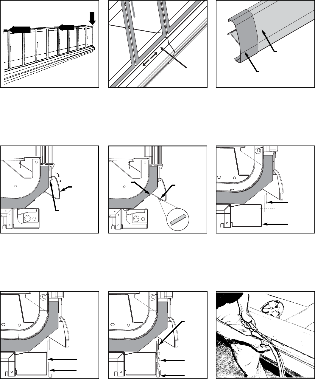
12
Add Sealant to Top Case Joint.
Once cases are pushed tightly togeth-
er and bolted run a bead of sealant
along the top joint.
11
Bolt Cases Together Using Bolt
Holes Provided
Push cases tightly together. Bolt
cases together through the holes
provided. Tighten until all margins
are equal; do not over tighten. If bolt
5interferes with shelf positioning, it
may be removed once cases are set.
10
Loosen Master Bumper
Loosen screws on master bumper.
Move bumper joint to a position for
sliding between adjoining case
bumper.
BUMPER
SCREW
BUMPER
JOINT
1
2
3
5
7
6
4
7
Remove Outriggers
Remove cotter pin from outrigger by
cutting tie strap. Either pull the out-
rigger out from the front or insert a
crowbar into the tube from the back
and push the outrigger out. 8
Position Next Case In Line Up
Roll case approximately 6’ from
adjoining case. Remove casters on
the end nearest to the next case.
Allow casters to remain on opposite
end to assist in pushing cases togeth-
er - then remove them.
CAULK
OUTRIGGER
COTTER PIN
LOCATION
9
Remove Shipping Accessories
From Case. Add Sealant.
Remove anything from the case that
may interfere with case joining. Apply
the foam tape that is shipped loose in
the case to the end breakers on each
side of the case. Run a bead of
sealant around the entire end before
pushing cases tightly together.
CAULK
FOAM TAPE
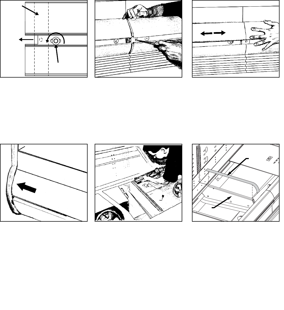
12
56
Apply acrylic tape over pipe chase seam.
Tape is found with the ship loose items
and acts as a watershed preventing
water from settling in case joint.
Seal joints along pipe chase seam
with the caulk provided.
Now that cases have been positioned and leveled, you may proceed to trim-out case line-
up. Trim parts have been designed to be applied easily with only a small number of fas-
teners required. Most external parts are adjustable to achieve almost invisible, snug-fit-
ting joints and a high level of excellence in fit and finish.
TRIM OUT
BUMPER
SCREW
BUMPER
JOINT
1
Adjust polymer master bumper joints,
if required. First loosen bumper
screws. 2
Slide bumper joint to the center of the
joint between the two cases. Use
screw driver in hole provided. 3
Slide master bumper left or right to
close seam as required. Bumper joint
neatly finishes any gap that may
remain.
4
Close seam where bumper joins case
end. Bumper joint closes seam that
may develop if master bumper is
moved away from end to close case-
to-case joint seam.
ACRYLIC
TAPE
PIPE
CHASE
11
10
9
12
Attach the upper kickplate retainer,
which is shipped loose with the case.
Line up the retainer with the kickplate
bracket and secure with the screws
provided. The kickplate brackets are
shipped loose with the ORZ and
ORZH models but come installed on
the ONRZ and ONRZH models.
If the case has a Streamlyne front
style the bumper may be shipped
loose in the case. Before installing
bumper on the case install the exter-
nal bumper joint on the Streamlyne
bumper. Simply slide the joint over
the bumper for either case-to-case or
case-to-end joints.
151413 Insert nose bumper into master
bumper channel. Roll nose bumper
into channel along entire lineup (up to
96’). We recommend that the nose
bumper be left in the store 24 hours
before installing. DO NOT STRETCH
the bumper during installation as it
will shrink to its original length and
leave a gap.
Insert top of kickplate into the upper
kickplate retainer. Slide the kickplate
up into retainer then down on the “J”
rail.
Attach the “J” rail, which is shipped
loose with the case. Line up the rail
with the kickplate bracket and secure
with the screws provided.
Once the Streamlyne bumper has
been properly seated, attach the
bumper to the tank with the screws
provided. Insert the bumper align-
ment pin into the underside of the
bumper to help align it to the bumper
on the next case.
Place the hook of the Streamlyne
bumper on the lip of the master
bumper bracket and rotate the
bumper down while pushing it in.
Once the top edge of the bumper has
slipped under the color band make
sure it is pushed in as far as it will go.
13
7
Insert exterior cornice joint at every
case joint. The exterior cornice joints
are shipped loose with each case
COLOR
BAND
8
Close joints on color band by sliding
the panels together. The color band
can be moved left or right as required
to allow adjustment.
KICKPLATE
BRACKET
UPPER
KICKPLATE
RETAINER
KICKPLATE
BRACKET
“J” RAIL
KICKPLATE
UPPER
KICKPLATE
RETAINER
“J” RAIL
EXTERNAL
BUMPER JOINT
STREAMLYNE
MASTER BUMPER
MASTER BUMPER
BRACKET
BUMPER
ALIGNMENT PIN
LOCATION
STREAMLYNE
MASTER
BUMPER
SCREW
C
L
31 9/16 in
[80.2 cm]
(STANDARD)
35 1/8 in
[89.2 cm]
(STANDARD)
**
28 5/8 in
[72.7 cm]
(STANDARD)
39 1/4 in
[99.7 cm]
(STANDARD)
REFRIGERATION
1 1/2 in
[3.8 cm]
{END}
8 11/16 in [22.1 cm]
FRONT OF CASE
NOTES:
** RECOMMENDED STUB-UP CENTERLINE FOR ELECTRICAL AND HUB DRAINS
z SUCTION LINE (ALL LENGTHS) 1/2"
z LIQUID LINE (ALL LENGTHS) - 3/8", LIQUID LINE w/ HOT GAS DEFROST (ALL LENGTHS) - 1/2"
60 in [152.4 cm] {2 Door}
90 in [228.6 cm] {3 Door}
120 in [304.8 cm] {4 Door}
150 in [381.0 cm] {5 Door}
180 in [457.2 cm] {6 Door}
4 in [10.2 cm]
PIPING-TO-TOP
(OPTIONAL)
12 3/4 in [32.4 cm] 3 3/8 in [8.6 cm]
REAR REFRIGERATION
(13 15/16" off of floor)
42 11/16 in
[108.4 cm]
(STANDARD)
27 9/16 in
[70.0 cm]
(NARROW)
**
23 1/4 in
[59.1 cm]
(NARROW)
24 3/16 in
[61.4 cm]
(NARROW)
31 7/8 in
[81.0 cm]
(NARROW)
35 3/8 in
[89.8 cm]
(NARROW)
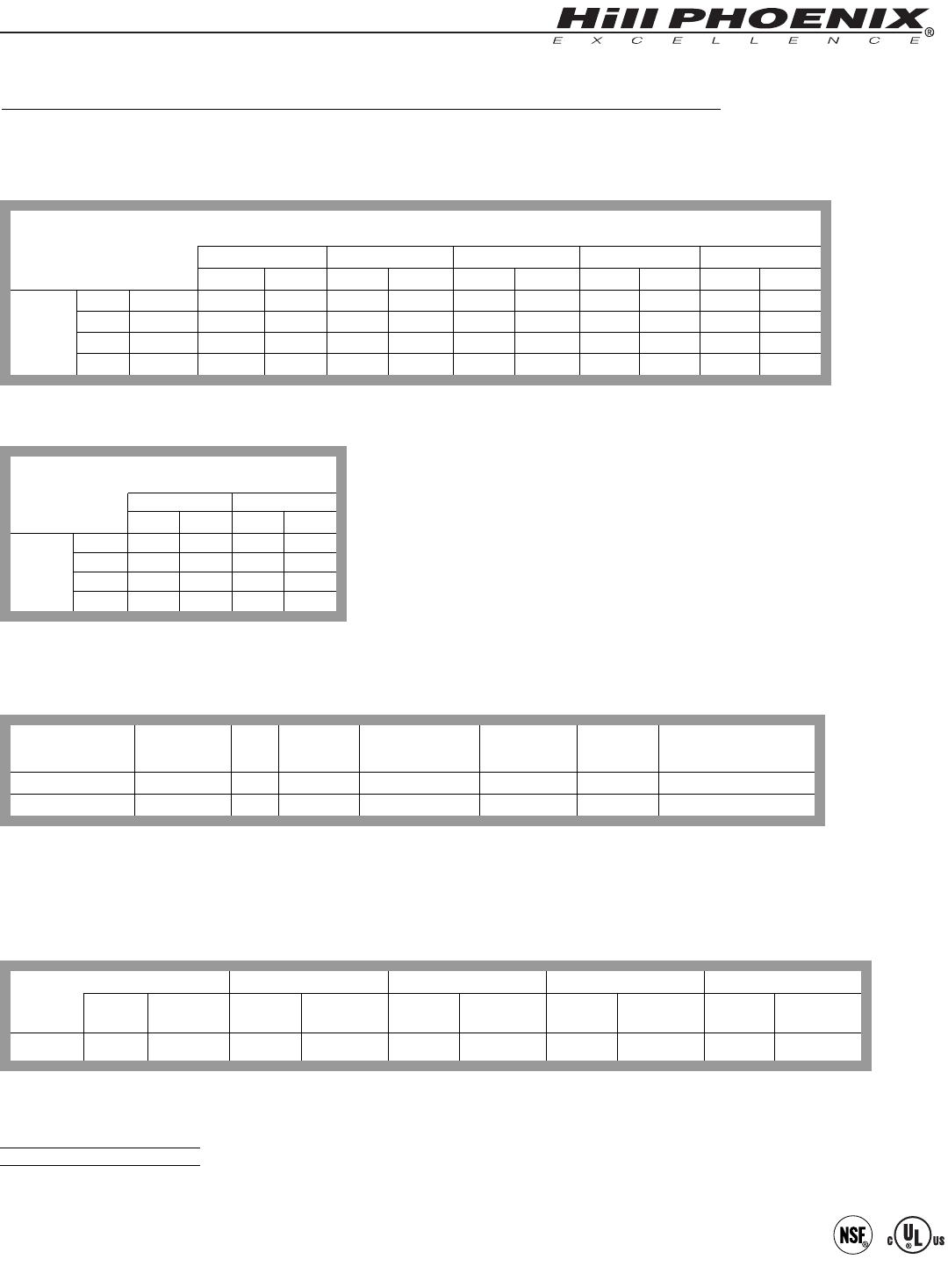
REFRIGERATION PIPING
14
Refrigeration components and the coil
outlet hole are located to provide the best
access for installation and maintenance. As
the diagrams below indicates, the coil outlet
hole is positioned forward on the right hand
side of the case, fully visible in front of the fan
plenum. An optional piping-to-top configura-
tion can be ordered that runs the refrigeration
lines through the top of the case at the location
shown below. Note that on the narrow six
door case an extra support is present on the
end frames that requires case-to-case piping
to be fed through the opening.
The expansion valve and other con-
trols are located on the left-hand side of the
case, are accessible without lifting the fan
plenum, and may be reached by lifting only
the left hand deck pan.
If it becomes necessary to penetrate
the case bottom make certain it is sealed
afterward with canned-foam sealant and
white RTV.
REMOVE SHIPPING BLOCKS
REMOVE THE SHIPPING BLOCKS
THAT PROTECT THE REFRIGERATION
LINES DURING SHIPMENT BEFORE
OPERATING THE CASE.
CANOPY
FRONT OF CASE
PIPING-TO-TOP
MODEL
ORB, ORBH, ONRB & ONRBH
NARROW 6 DOOR SUPPORT
EXTRA FRAME
SUPPORT REFRIGERATION LINES
PIPED-TO-TOP
15
PLUMBING
The drain outlet is located front and
center of the cases for convenient access and
is especially molded out of ABS material. The
“P” trap, furnished with the case, is construct-
ed of schedule 40 PVC pipe. Care should be
given to assure that all connections are water
tight and sealed with the appropriate PVC or
ABS cement.
The lines can be run left or right of the
tee with the proper pitch to satisfy local
drainage requirements.
The kickplate is shipped loose with the
case for field installation, therefore you
should have open access to the drain line
area.
If the kickplate has been installed, you
will find it very easy to remove. See instruc-
tions below, or the trim out section of this
manual on page 13.
C
L
31 9/16 in
[80.2 cm]
(STANDARD)
1 1/2" PVC DRAIN
CONNECTION
33 9/16 in
[85.3 cm]
(STANDARD)
39 1/4 in
[99.7 cm]
(STANDARD)
1 1/2 in
[3.8 cm]
{END}
FRONT OF CASE
NOTES:
** RECOMMENDED STUB-UP CENTERLINE FOR ELECTRICAL AND HUB DRAINS
42 11/16 in
[108.4 cm]
(STANDARD)
26 7/8 in
[68.3 cm]
(NARROW)
24 3/16 in
[61.4 cm]
(NARROW)
31 7/8 in
[81.0 cm]
(NARROW)
35 3/8 in
[89.8 cm]
(NARROW)
35 1/8 in
[89.2 cm]
(STANDARD)
**
27 9/16 in
[70.0 cm]
(NARROW)
**
60 in [152.4 cm] {2 Door}
90 in [228.6 cm] {3 Door}
120 in [304.8 cm] {4 Door}
150 in [381.0 cm] {5 Door}
180 in [457.2 cm] {6 Door}
96 in [243.8 cm] {8' case}
144 in [365.8 cm] {12' case}
MODEL
ORB, ORBH, ONRB & ONRBH
HOW TO REMOVE KICKPLATE
LIFT UP FROM “J”
RAIL AND PULL OUT
KICKPLATE
16
ELECTRICAL HOOKUP
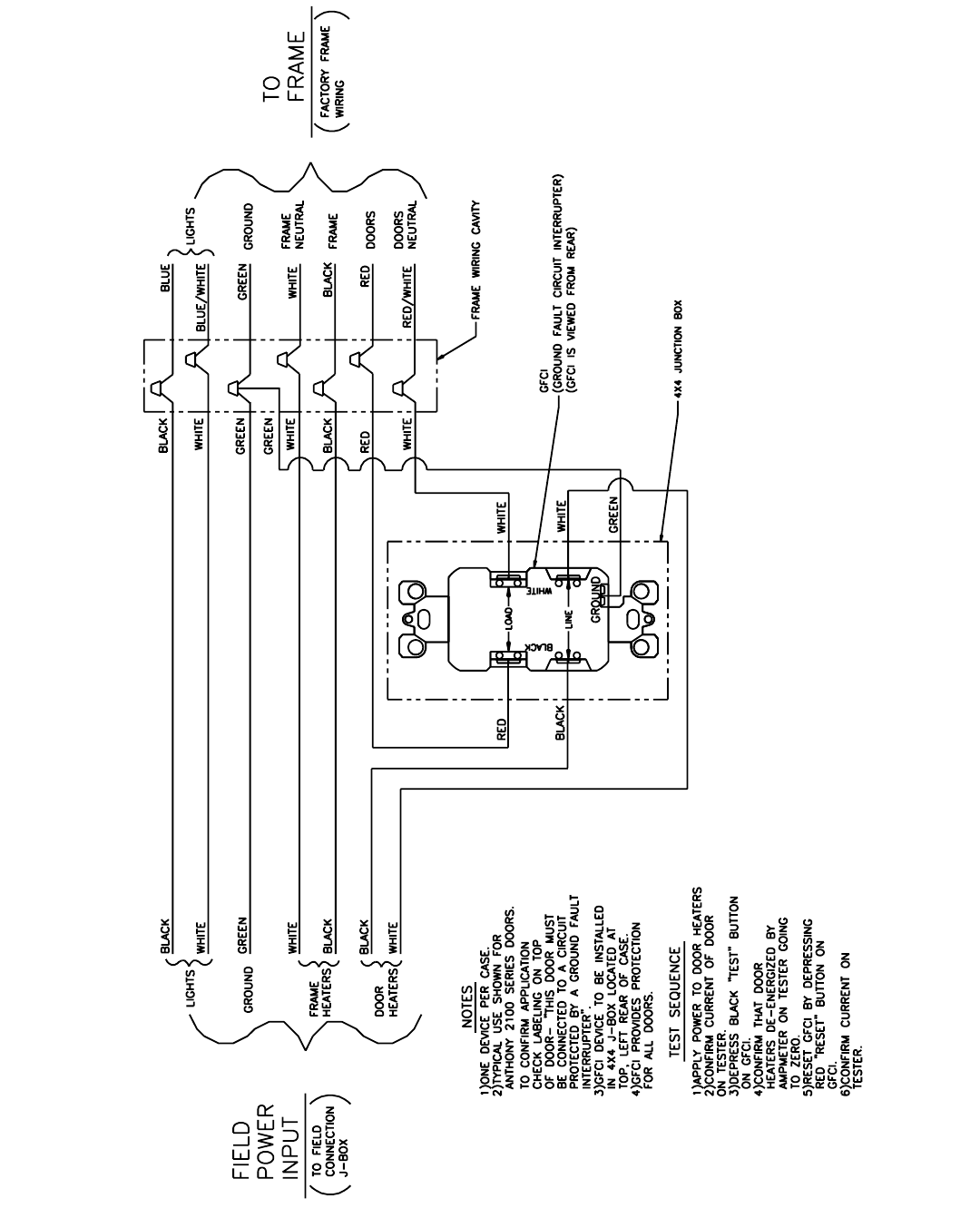
For case-to-case wiring, run “greenfield”,
or other conduit, between junction boxes.
When connecting to the junction box on the
bottom left side of the case, field wiring should
exit the junction box from the right hand side,
furthest away from case wiring, increasing room
inside for wire connecting.
Electrical hookups are made to a
junction box located at the bottom left
hand front of the case. At the owners
option the case made be wired to a junction
box located on the top left rear of the case.
DEFROST HEATERS, 208/240 VOLTS L1
L2
RED
BLUE
EVAPORATOR FANS, 120 VOLT
ANTI-CONDENSATE HEATERS, 120 VOLT
WIRE NUMBERCOMPONENT COLOR CODING
BLACK
TEMPERATURE CONTROL, 120 VOLT
LIGHTS, 120 VOLT
DEFROST TERMINATION CONTROL, 120 VOLT
WHITE
3
4
11
12
13
14
19
20
21
WHITE
BLACK
WHITE
BLACK
YELLOW
YELLOW
PURPLE
ORANGE23
WIRING NUMBERS AND COLORS
EQUIPMENT GROUNDING CONDUCTOR GREEN
-
BLACK
WHITE
DOOR & FRAME ANTI-COND. HEATERS, 120 VOLT 15
16
WIRING-TO-TOP
CONTINUOUS
RACEWAY
JUNCTION BOX
COVER
JUNCTION BOX
CANOPY
WIRING-TO-JUNCTION BOX
JUNCTION
BOX COVER
JUNCTION
BOX
C
L
34 11/16 in
[88.1 cm]
(STANDARD)
31 9/16 in
[80.2 cm]
(STANDARD)
10 in
[25.4 cm]
JUNCTION BOX
(STANDARD)
8 in [20.3 cm]
WIRING-TO-TOP
(OPTIONAL)
ELECTRICAL
35 1/8 in
[89.2 cm]
(STANDARD)
**
39 1/4 in
[99.7 cm]
(STANDARD)
REFRIGERATION
1 1/2 in
[3.8 cm]
{END}
FRONT OF CASE
NOTES:
** RECOMMENDED STUB-UP CENTERLINE FOR ELECTRICAL AND HUB DRAINS
z WIRING-TO-THE-TOP- ADDS APPROXIMATELY 1 INCH TO CASE HEIGHT
42 11/16 in
[108.4 cm]
(STANDARD) 31 7/8 in
[81.0 cm]
(NARROW)
24 3/16 in
[61.4 cm]
(NARROW)
27 5/16 in
[69.4 cm]
(NARROW)
35 3/8 in
[89.8 cm]
(NARROW)
27 9/16 in
[70.0 cm]
(NARROW)
**
60 in [152.4 cm] {2 Door}
90 in [228.6 cm] {3 Door}
120 in [304.8 cm] {4 Door}
150 in [381.0 cm] {5 Door}
180 in [457.2 cm] {6 Door}
96 in [243.8 cm] {8' case}
144 in [365.8 cm] {12' case}
16 1/16 in [40.8 cm]
18 9/16 in [47.1 cm]
MODEL
ORB, ORBH, ONRB & ONRBH
17
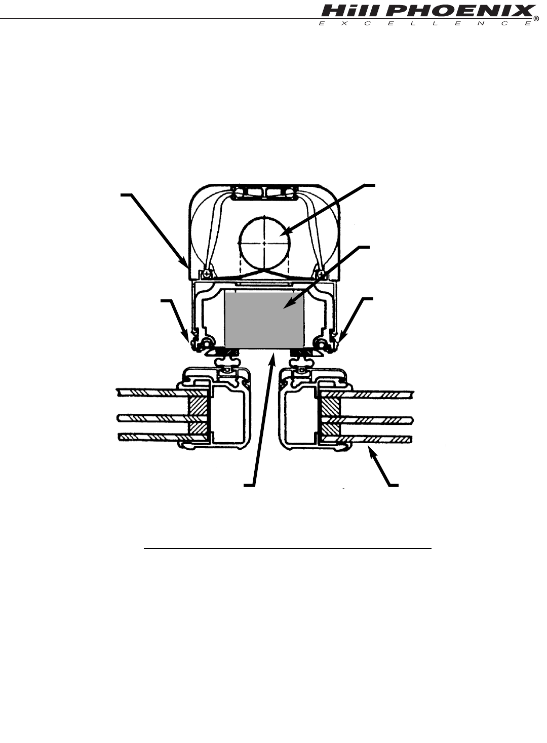
BALLASTS ACCESS
The electronic ballasts that operate the vertical prism door lights are located in the door frame for
Anthony® door frames.
ANTHONY®FRAMES
1. REMOVE CORNER BEADS (2)
2. REMOVE ACCESS COVER
3. REPLACE BALLAST
ANTHONY®FRAMES
STEPS TO REPLACE THE BALLAST
1. CORNER BEAD
2. ACCESS COVER
3. BALLAST
DOOR
MULLION LIGHT
1. CORNER BEAD
18
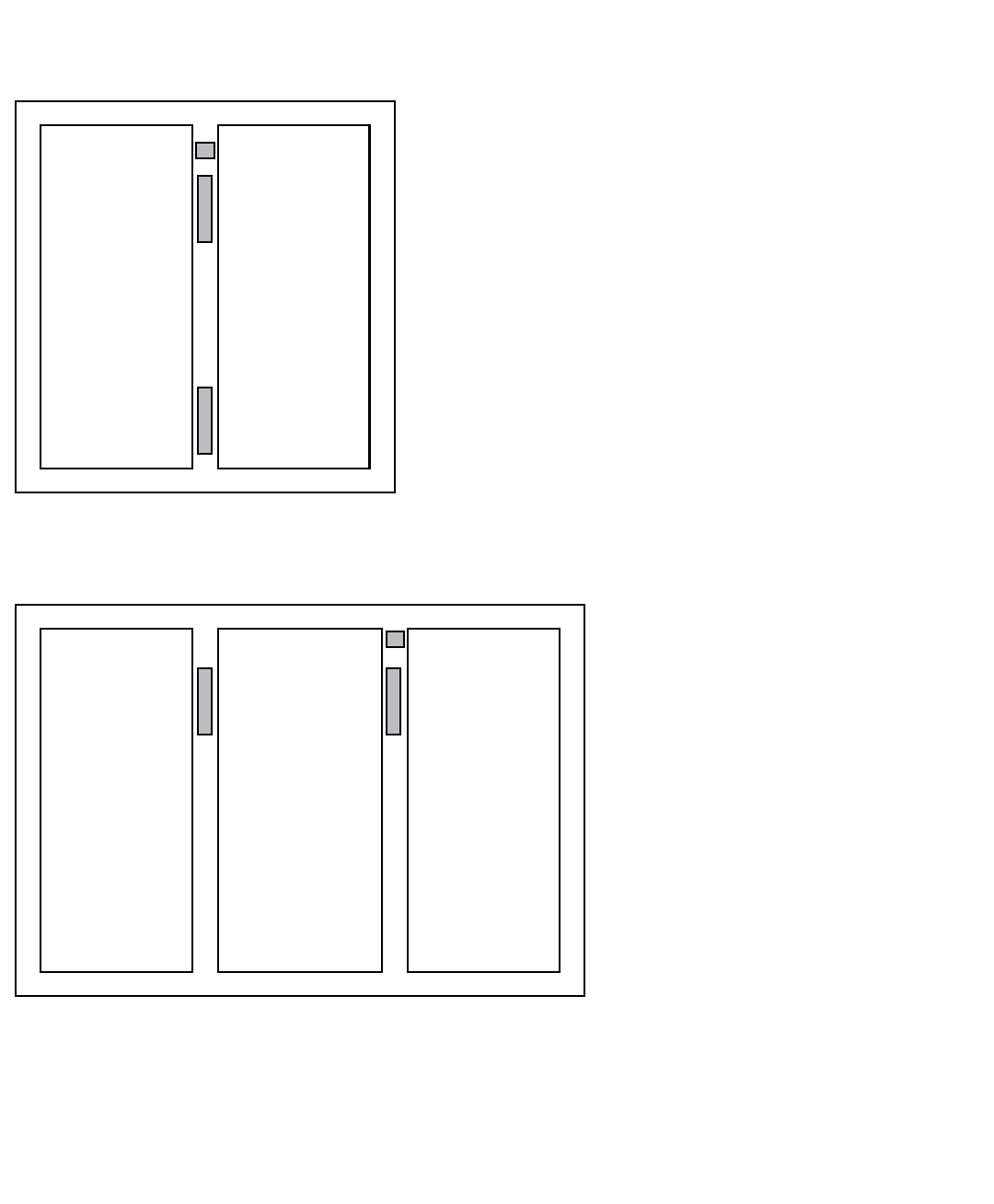
BALLAST LOCATIONS
POWER LEADS
LAMP LEADS
LAMP 1
LAMP 2
LAMP 3
FILTER
BALLAST FOR
LAMP 2
BALLAST FOR
LAMPS 1 & 3
POWER LEADS
LAMP LEADS
LAMP 1
FILTER
BALLAST FOR
LAMPS 3 & 4
LAMP 2
LAMP 3
LAMP 4
BALLAST FOR
LAMPS 1 & 2
2 DOOR MODELS
3 DOOR MODELS
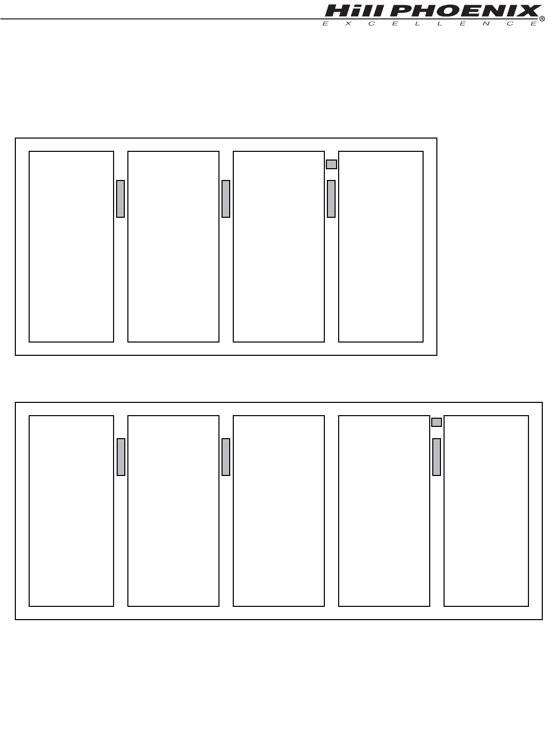
19
POWER LEADS
LAMP LEADS
LAMP 1
FILTER
BALLAST FOR
LAMPS 4 & 5
LAMP 2
LAMP 3
LAMP 4
LAMP 5
BALLAST FOR
LAMP 3
BALLAST FOR
LAMPS 1 & 2
POWER LEADS
LAMP LEADS
LAMP 1
BALLAST FOR
LAMPS 5 & 6
FILTER
LAMP 2
LAMP 3
LAMP 4
LAMP 5
LAMP 6
BALLAST FOR
LAMPS 3 & 4
BALLAST FOR
LAMPS 1 & 2
4 DOOR MODELS
5 DOOR MODELS
20
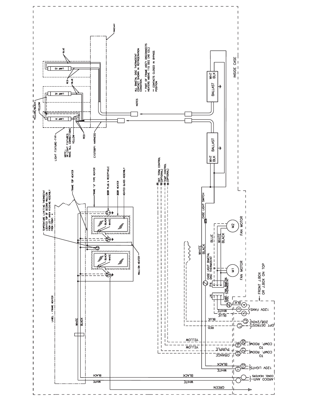
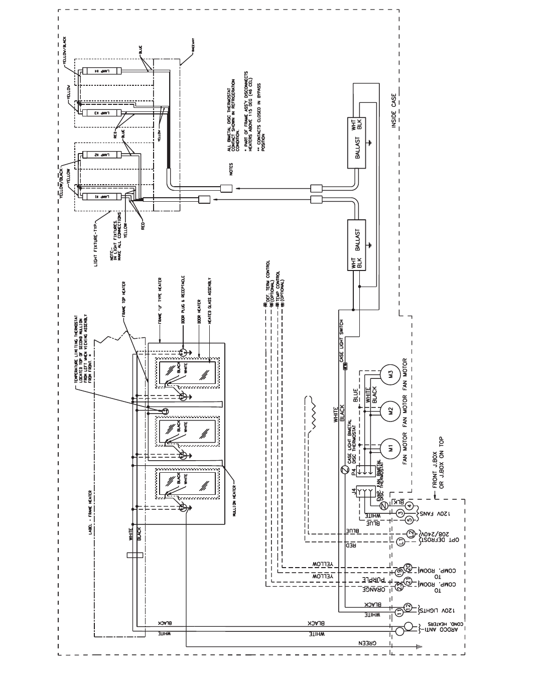
WIRING DIAGRAMS-
15
16
ORB, ORBH,
ONRB & ONRBH
2 DOOR
21
WIRING DIAGRAMS-
15
16
ORB, ORBH,
ONRB & ONRBH
3 DOOR - 8’
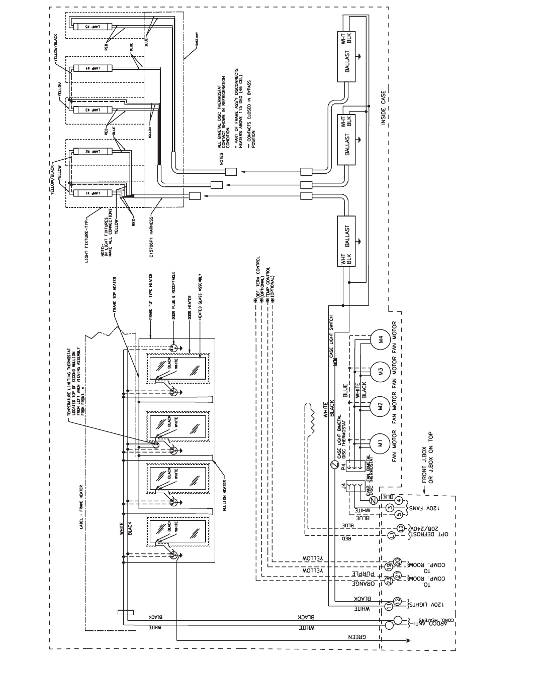
22
WIRING DIAGRAMS-
15
16
ORB, ORBH,
ONRB & ONRBH
4 DOOR - 12’
23
WIRING DIAGRAMS-
BLACK
WHITE
RED
C15706P1 HARNESS
YELLOW/BLACK
YELLOW
YELLOW
BLUE
COMP. ROOM
COMP. ROOM
OPT DEFROST
19
120V LIGHTS
12 21
11 23
20
208/240V
L1
WHITE
YELLOW
GREEN
BLACK
YELLOW
BLK
120V FANS
54
3
WHITE
INSIDE CASE
M1
FAN MOTOR
J4 P4
M2
FAN MOTOR
M5
FAN MOTOR
TO
TO
OR J.BOX ON TOP
FRONT J.BOX
MULLION HEATER
HEATED GLASS ASSEMBLY
FRAME "U" TYPE HEATER
DOOR PLUG & RECEPTACLE
DOOR HEATER
FRAME TOP HEATER
FROM LEFT WHEN VIEWING ASSEMBLY
LOCATED TOP OF SECOND MULLION
TEMPERATURE LIMITING THERMOSTAT
FROM FRONT. *
LAMP #2
LAMP #1
YELLOW
BLUE
RED
LIGHT FIXTURE-TYP.
LAMP #4
LAMP #3
RACEWAY
BLUE
YELLOW
YELLOW/BLACK
BLUE
WHITE
BLACK
WHT
BLK BALLAST WHT
BLK
BALLAST
15
ANTI-
16
COND. HEATERS
WHITE
BLACK BLACK
WHITE
SCAN-X SENSOR BUTTON LOC.-TOP
CASE LIGHT BIMETAL
DISC THERMOSTAT
BLACK
WHITE
CASE LIGHT SWITCH
EVAP. FAN BIMETAL
DISC THERMOSTAT
ORANGE
PURPLE
L2
DEF. TERM CONTROL
(OPTIONAL)
TEMP CONTROL
(OPTIONAL)
NOTES ALL BIMETAL DISC THERMOSTAT
CONTACT SHOWN IN REFRIGERATION
CONDITION.
* PART OF FRAME ASS’Y DISCONNECTS
HEATERS ABOVE 115 DEG (46 CEL)
** CONTACTS CLOSED IN BYPASS
POSITION
WHITE
BLACK
BLACK
WHITE WHITE WHITE
BLACK BLACK
M3
FAN MOTOR
BLK
WHT
BALLAST
FAN MOTOR
M4
BLACK
WHITE
YELLOW
LAMP #5
RED
LAMP #6
YELLOW/BLACK
BLUE
YELLOW
NOT USED
{
{
{
{
{
{
MAKE ALL CONNECTIONS
IN LIGHT FIXTURES.
NOTE:-
L1
L2
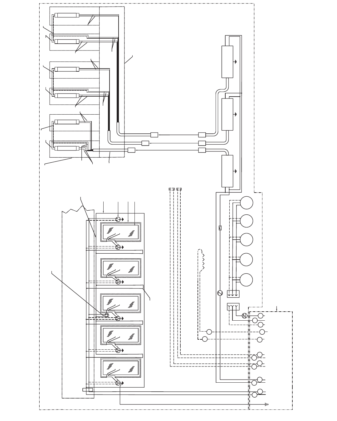
ORB, ORBH,
ONRB & ONRBH
5 DOOR
24
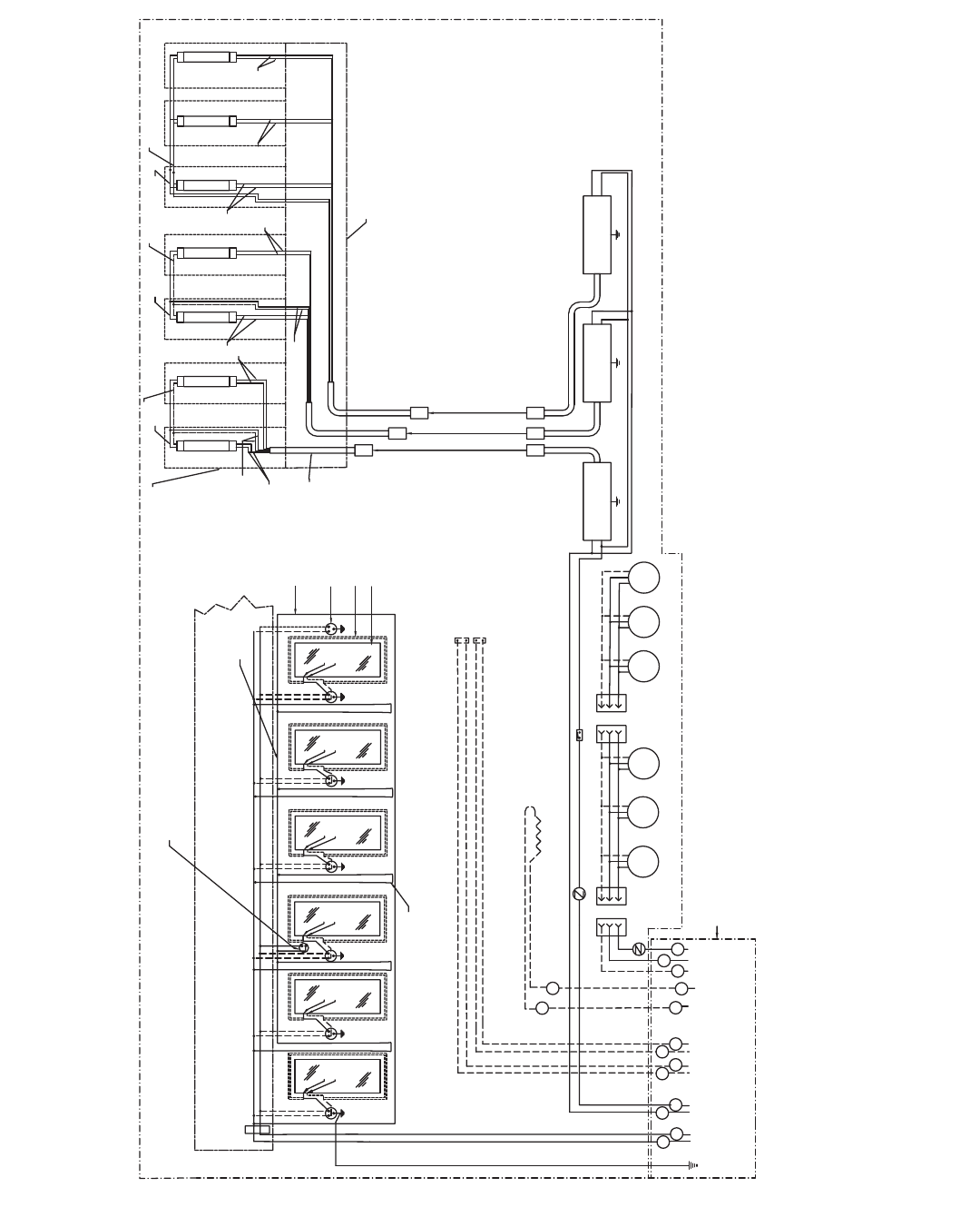
WIRING DIAGRAMS-
BLACK
WHITE
RED
C15706P1 HARNESS
YELLOW/BLACK
YELLOW
YELLOW
BLUE
COMP. ROOM
COMP. ROOM
OPT DEFROST
19
120V LIGHTS
12 21
11 23
20
208/240V
L1
WHITE
YELLOW
GREEN
BLACK
YELLOW
BLK
120V FANS
54
3
WHITE
INSIDE CASE
M1
FAN MOTOR
M2 M5
TO
TO
OR J.BOX ON TOP
FRONT J.BOX
MULLION HEATER
HEATED GLASS ASSEMBLY
FRAME "U" TYPE HEATER
DOOR PLUG & RECEPTACLE
DOOR HEATER
FRAME TOP HEATER
FROM LEFT WHEN VIEWING ASSEMBLY
LOCATED TOP OF SECOND MULLION
TEMPERATURE LIMITING THERMOSTAT
FROM FRONT. *
LAMP #2
LAMP #1
YELLOW
BLUE
RED
LIGHT FIXTURE-TYP.
LAMP #4
LAMP #3
RACEWAY
BLUE
YELLOW
YELLOW/BLACK
BLUE
WHITE
BLACK
WHT
BLK BALLAST WHT
BLK
BALLAST
15
ANTI-
16
COND. HEATERS
WHITE
BLACK BLACK
WHITE
CASE LIGHT BIMETAL
DISC THERMOSTAT
BLACK CASE LIGHT SWITCH
EVAP. FAN BIMETAL
DISC THERMOSTAT
ORANGE
PURPLE
L2
DEF. TERM CONTROL
(OPTIONAL)
TEMP CONTROL
(OPTIONAL)
NOTES ALL BIMETAL DISC THERMOSTAT
CONTACT SHOWN IN REFRIGERATION
CONDITION.
* PART OF FRAME ASS’Y DISCONNECTS
HEATERS ABOVE 115 DEG (46 CEL)
** CONTACTS CLOSED IN BYPASS
POSITION
WHITE
BLACK
BLACK
WHITE WHITE WHITE
BLACK BLACK
M3
BLK
WHT
BALLAST
M4
BLACK
WHITE
LAMP #5
BLUE
LAMP #6
YELLOW/BLACK
BLUE
RED
NOT USED
WHITE
BLACK
M6
LAMP #7
BLUE
J4 P4
FAN MOTOR FAN MOTOR FAN MOTOR FAN MOTOR FAN MOTOR
{
{
{
{
{
{
MAKE ALL CONNECTIONS
IN LIGHT FIXTURES.
NOTE:-
L1
L2
ORB & ORBH
6 DOOR
25
WIRING DIAGRAMS- GFI
26
CASE OPERATION
Glass Door Reach-in Beverage Merchandiser
ORB - 2, 3, 4, 5 & 6-door
All measurements are taken per ARI 1200 - 2002 specifications.
Medium Temperature Defrost Schedule
No. Per Day Hours
1 12 midnight
2 12 am - 12 pm
3 6 am - 2 pm - 10 pm
4 12 - 6 am - 12 - 6 pm
COMPONENT
5If timed off defrost is utilized. If electric or hot gas defrost is utilized case only requires 1 defrost per day.
6NOTE: - - - not an option on this case model.
Electric Defrost
Defrosts
Per Day
45
Model
ORB
Fail-safe
(min)
30
Termination
Temp. (°F)
47
Defrost Controls
Timed Off Defrost
Fail-safe
(min)
30
Termination
Temp. (°F)
40
Hot Gas Defrost
Fail-safe
(min)
24
Termination
Temp. (°F)
47
Reverse Air Defrost
Fail-safe
(min)
- - -6
Termination
Temp. (°F)
- - -
Run-Off
Time (min)
6 - 8
Guidelines & Control Settings
2BTUHs/door listed are for parallel operation. Conventional ratings may be approximated by multiplying listed rating by 1.04.
3 High efficiency fans reduce refrigeration load by 96 BTUHs/fan.
4Average discharge air velocity at peak of defrost.
8303
8003
BTUH/door2
Model
32
34
Evaporator
(°F)
36
38
38
40
Return Air
(°F)
380
380
Discharge Air Velocity4
(FPM)
Discharge Air
(°F)
ORB - Deli/Dairy
ORB - Beverage
Superheat Set
Point @ Bulb (oF)
6-8
6-8
Enh.
Enh.
Coil
Type
2-door
3-door
4-door
5-door
6-door
Standard Fans
Amps
1.00
1.50
2.00
2.50
3.00
Watts
60
90
120
150
180
Defrost Heaters
208 Volts
Amps
4.39
4.96
6.51
7.96
9.40
Watts
914
1032
1355
1655
1955
240 Volts
Amps
5.06
5.71
7.55
9.17
10.79
Watts
1215
1370
1813
2201
2589
Anti-Condensate
Heaters
120 Volts
Amps
1.01
1.49
1.96
2.40
2.92
Watts
121
179
235
288
350
Fans
per
Case
2
3
4
5
6
High Efficiency
Fans
120 Volts
Amps
0.31
0.46
0.61
0.77
0.92
Watts
18.4
27.6
36.8
46.0
55.2
Electrical Data
ORB
Model
120 Volts
1Not applicable.
Maximum
Lighting
120 Volts
Amps
1.50
1.90
2.40
2.90
3.40
Watts
180
228
288
348
408
Typical per
Light Row
120 Volts
Amps
NA1
NA
NA
NA
NA
Watts
NA
NA
NA
NA
NA
Lighting Data
2-door
3-door
4-door
5-door
6-door
ORB
Model
27
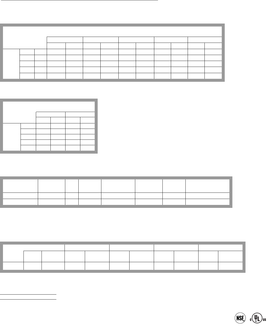
High Glass Door Reach-in Beverage Merchandiser
ORBH - 2, 3, 4, 5, 6-door, 8’ & 12’
COMPONENT
All measurements are taken per ARI 1200 - 2002 specifications.
Medium Temperature Defrost Schedule
No. Per Day Hours
1 12 midnight
2 12 am - 12 pm
3 6 am - 2 pm - 10 pm
4 12 - 6 am - 12 - 6 pm
1Not applicable.
Maximum
Lighting
120 Volts
Amps
1.50
1.90
2.40
2.90
3.40
1.90
2.40
Watts
180
228
288
348
408
228
288
Typical per
Light Row
120 Volts
Amps
NA1
NA
NA
NA
NA
NA
NA
Watts
NA
NA
NA
NA
NA
NA
NA
Lighting Data
2-door
3-door
4-door
5-door
6-door
8’
12’
ORBH
Model
2-door
3-door
4-door
5-door
6-door
8’
12’
Standard Fans
Amps
1.00
1.50
2.00
2.50
3.00
1.50
2.00
Watts
60
90
120
150
180
90
120
Defrost Heaters
208 Volts
Amps
4.39
4.96
6.51
7.96
9.40
3.85
5.78
Watts
914
1032
1355
1655
1955
800
1200
240 Volts
Amps
5.06
5.71
7.55
9.17
10.79
4.44
6.67
Watts
1215
1370
1813
2201
2589
1065
1600
Anti-Condensate
Heaters
120 Volts
Amps
1.06
1.55
2.07
2.54
3.07
1.61
2.23
Watts
127
186
248
305
368
193
268
Fans per
Case
2
3
4
5
6
3
4
High Efficiency
Fans
120 Volts
Amps
0.31
0.46
0.61
0.77
0.92
0.70
0.93
Watts
18.4
27.6
36.8
46.0
55.2
42
56
Electrical Data
ORBH
Model
120 Volts
6If timed off defrost is utilized. If electric or hot gas defrost is utilized case only requires 1 defrots per day.
7NOTE: - - - not an option on this case model.
Electric Defrost
Defrosts
Per Day
46
Model
ORBH
Fail-safe
(min)
30
Termination
Temp. (°F)
47
Defrost Controls
Timed Off Defrost
Fail-safe
(min)
30
Termination
Temp. (°F)
40
Hot Gas Defrost
Fail-safe
(min)
24
Termination
Temp. (°F)
47
Reverse Air Defrost
Fail-safe
(min)
- - -7
Termination
Temp. (°F)
- - -
Run-Off
Time (min)
6 - 8
Guidelines & Control Settings
2ORBH-8’ has 3 doors, ORBH-12’ has 4 doors.
3BTUHs/door listed are for parallel operation. Conventional ratings may be approximated by multiplying listed rating by 1.04.
4 High efficiency fans reduce refrigeration load by 96 BTUHs/fan.
5Average discharge air velocity at peak of defrost.
8304
8004
9304
9004
BTUH/door3
Model2
32
34
32
34
Evaporator
(°F)
36
38
36
38
38
40
38
40
Return Air
(°F)
280
280
280
280
Discharge Air Velocity5
(FPM)
Discharge Air
(°F)
ORBH-2, 3, 4, 5 & 6dr - Deli/Dairy
ORBH-2, 3, 4, 5 & 6dr - Beverage
ORBH-8’ & 12’ Deli/Dairy
ORBH-8’ & 12’- Beverage
Superheat Set
Point @ Bulb (oF)
6-8
6-8
6-8
6-8
Enh.
Enh.
Enh.
Enh.
Coil
Type
28
CASE OPERATION
1Not applicable.
All measurements are taken per ARI 1200 - 2002 specifications.
Medium Temperature Defrost Schedule
No. Per Day Hours
1 12 midnight
2 12 am - 12 pm
3 6 am - 2 pm - 10 pm
4 12 - 6 am - 12 - 6 pm
6If timed off defrost is utilized. If electric or hot gas defrost is utilized case only requires 1 defrost per day.
7NOTE: - - - not an option on this case model.
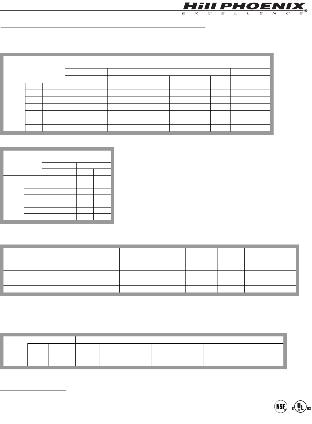
Electric Defrost
Defrosts
Per Day
46
Model
ONRB
Fail-safe
(min)
30
Termination
Temp. (°F)
47
Defrost Controls
Timed Off Defrost
Fail-safe
(min)
30
Termination
Temp. (°F)
40
Hot Gas Defrost
Fail-safe
(min)
24
Termination
Temp. (°F)
47
Reverse Air Defrost
Fail-safe
(min)
- - -7
Termination
Temp. (°F)
- - -
Run-Off
Time (min)
6 - 8
Maximum
Lighting
120 Volts
Amps
1.50
1.90
2.40
2.90
Watts
180
228
288
348
Typical per
Light Row
120 Volts
Amps
NA1
NA
NA
NA
Watts
NA
NA
NA
NA
Lighting Data
2-door
3-door
4-door
5-door
ONRB
Model
2-door
3-door
4-door
5-door
Standard Fans
Amps
1.00
1.50
2.00
2.50
Watts
60
90
120
150
Defrost Heaters
208 Volts
Amps
4.39
4.96
6.51
7.96
Watts
914
1032
1355
1655
240 Volts
Amps
5.06
5.71
7.55
9.17
Watts
1215
1370
1813
2201
Anti-Condensate
Heaters
120 Volts
Amps
1.01
1.49
1.96
2.40
Watts
121
179
235
288
Fans per
Case
2
3
4
5
High Efficiency
Fans
120 Volts
Amps
0.31
0.46
0.61
0.77
Watts
18.4
27.6
36.8
46.0
Electrical Data
ONRB
Model
120 Volts
COMPONENT
Guidelines & Control Settings
2All data listed is for an ONRB configured with 20” shelves.
3BTUHs/door listed are for parallel operation. Conventional ratings may be approximated by multiplying listed rating by 1.04.
4 High efficiency fans reduce refrigeration load by 96 BTUHs/fan.
5Average discharge air velocity at peak of defrost.
8304
8004
BTUH/door3
Model
32
34
Evaporator
(°F)
36
38
38
40
Return Air
(°F)
460
460
Discharge Air Velocity5
(FPM)
Discharge Air
(°F)
ONRB2- Deli/Dairy
ONRB2- Beverage
Superheat Set
Point @ Bulb (oF)
6-8
6-8
Enh.
Enh.
Coil
Type
Narrow Glass Door Reach-in Beverage Merchandiser
ONRB - 2, 3, 4 & 5-door
29
1Not applicable.
All measurements are taken per ARI 1200 - 2002 specifications.
Medium Temperature Defrost Schedule
No. Per Day Hours
1 12 midnight
2 12 am - 12 pm
3 6 am - 2 pm - 10 pm
4 12 - 6 am - 12 - 6 pm
Maximum
Lighting
120 Volts
Amps
1.50
1.90
2.40
2.90
Watts
180
228
288
348
Typical per
Light Row
120 Volts
Amps
NA1
NA
NA
NA
Watts
NA
NA
NA
NA
Lighting Data
2-door
3-door
4-door
5-door
ONRBH
Model
2-door
3-door
4-door
5-door
Standard Fans
Amps
1.00
1.50
2.00
2.50
Watts
60
90
120
150
Defrost Heaters
208 Volts
Amps
4.39
4.96
6.51
7.96
Watts
914
1032
1355
1655
240 Volts
Amps
5.06
5.71
7.55
9.17
Watts
1215
1370
1813
2201
Anti-Condensate
Heaters
120 Volts
Amps
1.06
1.55
2.07
2.54
Watts
127
186
248
305
Fans per
Case
2
3
4
5
High Efficiency
Fans
120 Volts
Amps
0.31
0.46
0.61
0.77
Watts
18.4
27.6
36.8
46.0
Electrical Data
ONRBH
Model
120 Volts
COMPONENT
6If timed off defrost is utilized. If electric or hot gas defrost is utilized case only requires 1 defrost per day.
7NOTE: - - - not an option on this case model.
Electric Defrost
Defrosts
Per Day
46
Model
ONRBH
Fail-safe
(min)
30
Termination
Temp. (°F)
47
Defrost Controls
Timed Off Defrost
Fail-safe
(min)
30
Termination
Temp. (°F)
40
Hot Gas Defrost
Fail-safe
(min)
24
Termination
Temp. (°F)
47
Reverse Air Defrost
Fail-safe
(min)
- - -7
Termination
Temp. (°F)
- - -
Run-Off
Time (min)
6 - 8
Guidelines & Control Settings
2All data listed is for an ONRBH configured with 20” shelves.
3BTUHs/door listed are for parallel operation. Conventional ratings may be approximated by multiplying listed rating by 1.04.
4 High efficiency fans reduce refrigeration load by 96 BTUHs/fan.
5Average discharge air velocity at peak of defrost.
8304
8004
BTUH/door3
Model
32
34
Evaporator
(°F)
36
38
38
40
Return Air
(°F)
405
405
Discharge Air Velocity5
(FPM)
Discharge Air
(°F)
ONRBH2- Deli/Dairy
ONRBH2- Beverage
Superheat Set
Point @ Bulb (oF)
6-8
6-8
Enh.
Enh.
Coil
Type
High Narrow Glass Door Reach-in Beverage Merchandiser
ONRBH - 2, 3, 4 & 5-door
30
DEFROST AND TEMP CONTROL
This case is equipped with either
Electric, Hot Gas, or Timed-Off defrost at the
owners option. The sensor bulb and probe
for electric defrost termination control, the
sensor bulb for timed-off defrost termination
control, and the sensor bulb for temperature
control are all located behind the rear baffle
at the location shown in illustration 1below.
The discharge air probe is located behind a
3 1/2” plug button on the top flue panel also
shown in diagram 1. The hot gas defrost ter-
mination sensor bulb and probe are attached
to the dump line, as shown in diagram 2
below, which is in the front, left hand side of
the case.
The defrost termination control
thermostat and the temperature control
thermostat are located inside the junction
box on the lower, left front of the case as
shown in diagram 3.
It is important to consult the control
setting guidelines shown on pages 26-29
before setting defrost times. Further
adjustment may be required depending
on store conditions
Discharge air probe location
(Behind 3 1/2” plug button in
top flue). Hot gas defrost termination
control sensor bulb and
probe location.
THERMOSTAT
1
2
• Electric defrost termination control sensor bulb location
• Electric defrost termination probe location
• Temperature control sensor bulb location
(Behind 3 -1/2” plug button in rear baffle).
3
CONTINUOUS
RACEWAY
31
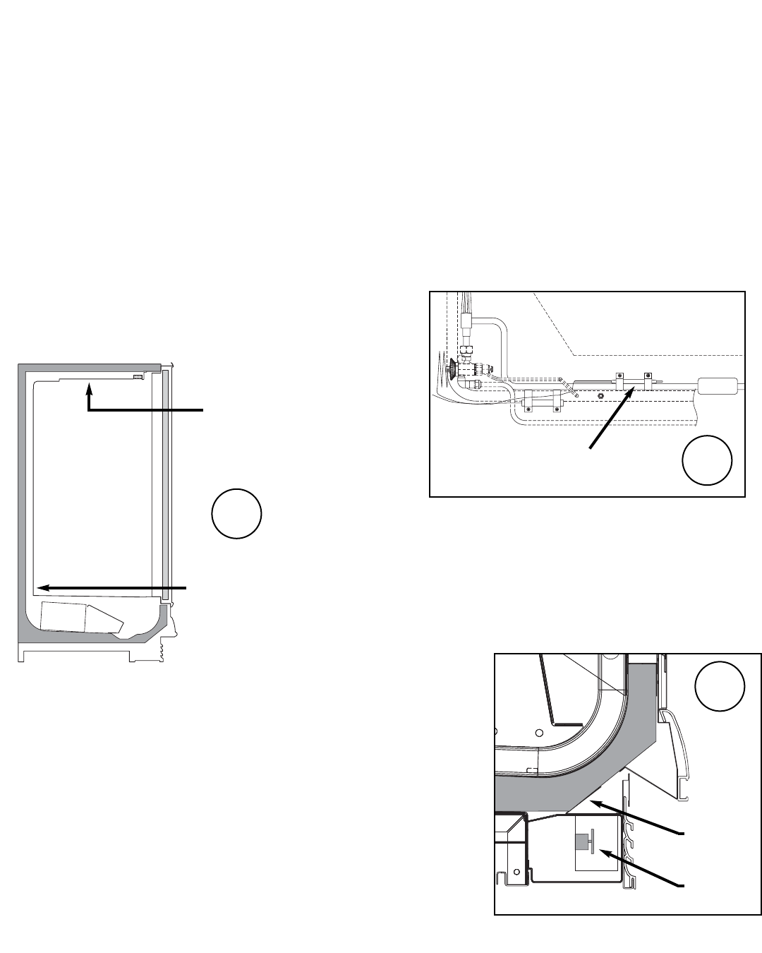
AIR FLOW AND PRODUCT LOADING
Cases have been designed to provide maxi-
mum product capacity within the refrigerated
air envelope. It is important that you do not
overload the food product display so that it
impinges on the air flow pattern.
DISCHARGE..............1
LOAD LIMIT...............2
AIR FLOW..................3
RETURN AIR GRILL...4
Overloading will cause malfunction and the
loss of proper temperature levels, particularly
when discharge and return air sections are
covered. Please keep products within the load
limit lines shown on these diagrams.
4
3
2
1
MODEL
ORB, ORBH,
ONRB & ONRBH
32
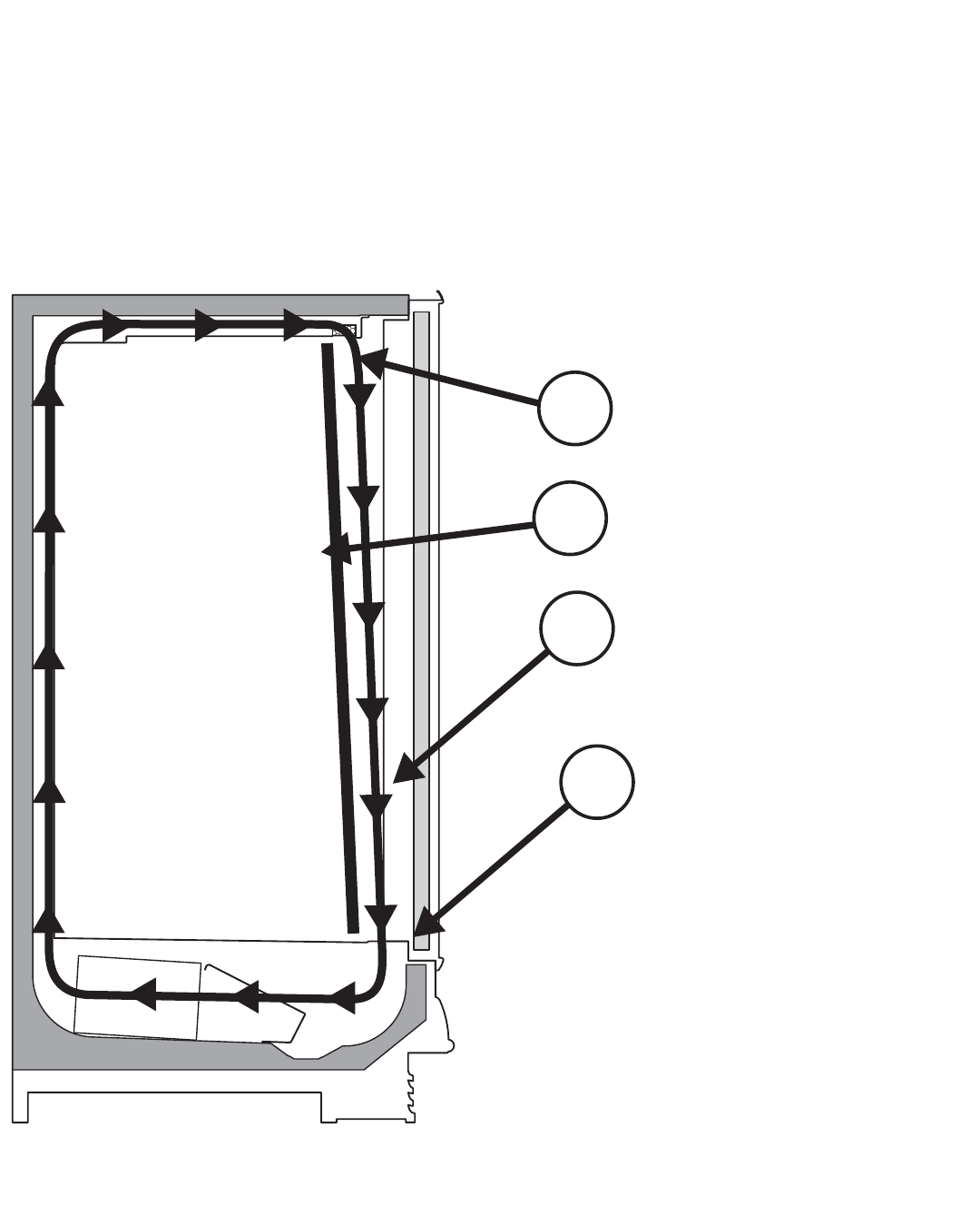
USE AND MAINTENANCE
CASE CLEANING
Case is designed to facilitate cleaning. There is a wide
radius formed on the front and back of the inside bottom of
the tank (ORB & ORBH) that helps accelerate liquid flow
and eliminates difficult-to-clean sharp corners. All surfaces
pitch to a deep-drawn drain trough that angles toward the
front and center of case where the waste outlet is located
for easy access.
The coil is covered to keep food fluids from entering,
but the cover lifts up easily when coil cleaning is desired.
The single piece fan plenum lifts up for cleaning, exposing a
major portion of the inside bottom of the tank. Make certain
fan plenum is properly closed after cleaning to avoid air
leaks.
CLEANING PROCEDURES
• A periodic cleaning schedule should be established to maintain proper sanitation, insure maximum operating efficiency, and
avoid the corrosive action of food fluids on metal parts that are left on for long periods of time. We recommend cleaning once
a week.
• To avoid shock hazard, be sure all electrical power is turned off before cleaning. In some installations, more than one
disconnect switch may have to be turned off to completely de-energize the case.
• Check waste outlet to insure it is not clogged before starting the cleaning process and avoid introducing water faster than the
case drain can carry it away.
• Avoid spraying cleaning solutions directly on fans or electrical connections.
• Provide a temporary separator between those cases which are being cleaned and those which are not.
• Allow cases to be turned off long enough to clean any frost or ice from coil and flue areas.
• Remove and clean discharge honeycomb. You may need to use spray detergent and a soft, long bristle brush.
• Use mild detergent and warm water. When necessary, water and baking soda solution will help remove case odors. Avoid
abrasive scouring powders or pads.
• Remove front panels and clean underneath the case with a broom and a long handled mop. Instructions for removing the
front panels can be found on page 13 of this manual.
• Use warm water and a disinfecting cleaning solution when cleaning underneath the cases.
• When cleaning antifog doors please refer to Appendix A, on page 37, for more details.
POSITIVE DRAIN OFF
SINGLE PIECE FAN PLENUM LIFT UP
SINGLE PIECE FAN
PLENUM SWINGS
UP FOR EASY
CLEANING
PLENUM
COIL
33
37 37
37 37
37
37 37
37 37
37 37
37 37 37
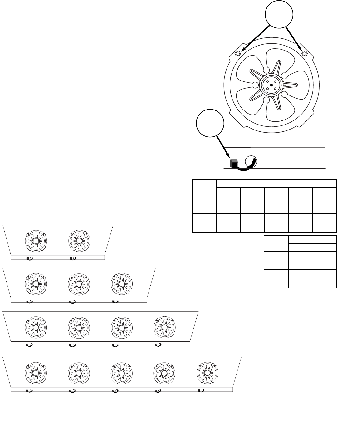
FANS
The evaporator fans are equipped with either
9 watt fan motors, 1550 RPM’s, or 12 watt fan
motors, 1650 RPM’s. Both motors have a counter
clockwise rotation when viewed from the shaft end.
The fan blades are 8” in diameter and the blades are
pitched as shown on the chart below. It is impor-
tant that the blade pitch be maintained as spec-
ified. Do not attempt a field modification by
altering the blades.
Fan motors may be changed with an easy
two-step process without lifting up the plenum,
thereby avoiding the necessity to unload the entire
product display to make a change:
1. Unplug the fan motor, easily accessible out
side the plenum
2. Remove two fasteners, then lift out the
entire fan basket
1
2
2 DOOR
3 DOOR - 8’
6 DOOR (2)
4 DOOR - 12’
5 DOOR
USE AND MAINTENANCE
Model ORB, ORBH, ONRB, & ONRBH
No.
Fans
Blade
Pitch
3 Door
3
37o
2 Door
2
37o
4 Door
4
37o
5 Door
5
37o
6 Door
6
37o
Model ORBH
No.
Fans
Blade
Pitch
12’
3
37o
8’
2
37o
34
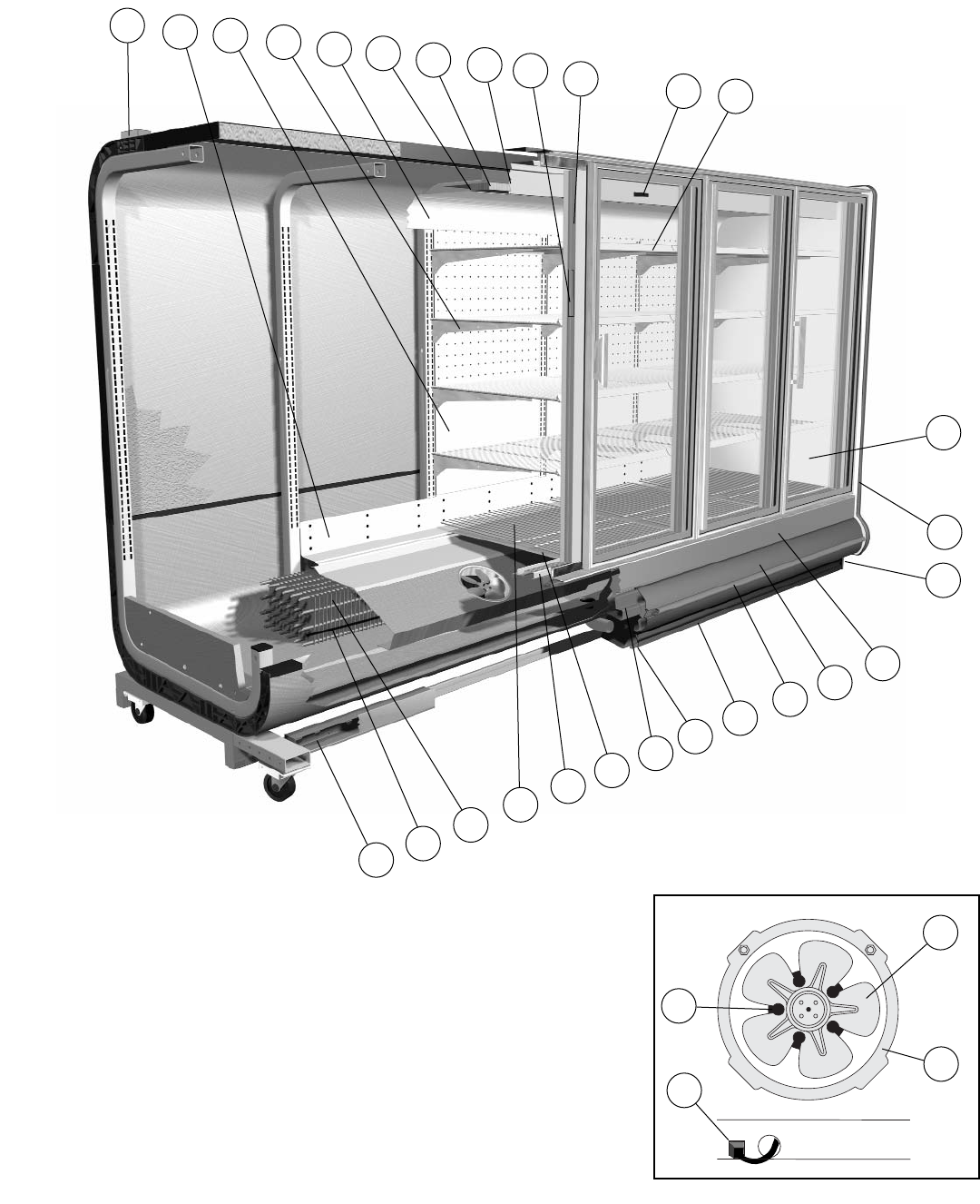
PARTS ORDERING
23
24
11
9
1
2
17
88
E02
E01
55
4
87
10
15
20
23
E08
E09
E11
E10
E20
12
13
69
81
82
83
25
56
78

35
Model ORB, ORBH, ONRB & ONRBH
Location Part Descriptions
Number
1Kickplate, Storm Grey
2Master Bumper, 3/4, 1/2, Featherstone, Smoke, White, French Vanilla, Black
3Lower Front Panel, Painted Custom Color (Not Shown)
4Color Band, Painted Custom Color or Stainless
9Deck Pan, Painted, Unpainted
10 Wire Shelving, White, With or Without Covers
11 Front Baffle, Aluminum
12 Honeycomb, 1”x 4”x 48”
13 Honeycomb Retainer, Painted
15 Upper Rear Baffle, Center or End
17 Nose Bumper, Polymer Custom Color
20 Lower Rear Baffle, Painted
23 Electrical Junction Box, (mounted on bottom left front or on top left rear)
24 “J” Rail, for Kickplate
25 Top Flue Panel, Painted
36 Plug Button, (Not Shown)
55 Door, Specify Mask Color, Ardco or Anthony, Door Handle Type, Low or
Medium Temperature Application, Left or Right Hand Swing
56 Door Frame, Ardco or Anthony, Low or Medium Temperature Application
69 Coil
78 Bumper Retainer
81 Bottom Wire Racks
82 Tag Moulding, PVC or Aluminum
83 Thermometer, Includes Bracket
87 End Assembly, Solid, Custom Color, Identify Left or Right hand, Color of
Panel, and Color of End Trim Color
88 End Kickplate, Painted, Stainless Steel
E01 Defrost Heaters
E02 Anti-Condensate Heaters, Discharge
E08 Ballast, Electronic, (Identify by brand name and model number)
E09 Fan Motor - STATE HIGH EFFICIENCY OR STANDARD
E10 Fan Blade
E11 Fan Basket, 8”
E20 Fan Cord-Set, High Efficiency or Standard

36
PARTS ORDERING
Procedure
1. Contact the Service Parts Department
Hill PHOENIX
1925 Ruffin Mill Road
Colonial Heights, Virginia 23834
Tel: 800-283-1109
Fax: 804-526-3897
2. Provide the following information about the part you are ordering:
• Model number and serial number of the case on which
the part is used.
• Length of part, if applicable, I.E. 60”, 90”, 120”, 150”, or 180”
• Color of part if painted, or color of polymer part.
• Whether part is for left hand or right hand application.
• Whether shelves are with or without lights.
• Quantity
*Serial plate is located on top flue panel on the left hand side of the
case (See illustrations on pages 4-7).
3. If parts are to be returned for credit, ask the Parts Department to
furnish you with a Return Materials Authorization Number.

37
APPENDIX - A
CLEANING INSTRUCTIONS FOR ANTIFOG COATING
Antifog Coating Cleaning Instructions (ANTIFOG B):
Materials
CAUTION:
1. Only use deionized or distilled water with 2% cleaning solution (P/N 05-14700-0001) to clean the
antifog coating. Do not apply cleaning solution full strength! Do not use commercial glass
cleaners containing ammonia or alcohol.
2. Only use soft lint-free wipers, such as Kimwipes or Soft-Tech paper wipers. Do not use cloth
rags or standard paper towels--these are abrasive and may damage the coating.
3. Do not use abrasive compounds to clean the coating. Do not use razor blades or sharp
instruments to remove residue from the coating.
Initial Cleaning (New Doors)
• Remove protective plastic film on the inside surface of the door.
• Apply diluted cleaning solution to the coating surface.
• Using gentle pressure, wipe glass over the entire surface with soft wipers once in the horizontal
direction, followed by once in the vertical direction.
• Gently dry the surface of the coating with new wipers.
• Repeat the above cleaning and drying cycle two more times.
Periodic Maintenance Cleaning
• Apply diluted cleaning solution to the coating surface.
• Using gentle pressure, wipe the entire surface of the glass with soft wipers.
• If the solution freezes on the surface of the glass, do not attempt to scrape off the ice from the
coating surface with force; either allow the inside surface of the door to warm up, or apply more
deionized water on the coating surface until the ice has melted enough to be removed by gentle
force.
• Gently dry the surface of the coating with new wipers.
• Please note that a newly cleaned freezer door glass will initially form a frost layer that will take
several hours to completely dissipate.
06-14654-0000 Rev X4

38
NOTES

6/00
WARRANTY
HEREINAFTER REFERRED TO AS MANUFACTURER
FOURTEEN MONTH WARRANTY. MANUFACTURER’S PRODUCT IS WARRANTED TO BE FREE FROM
DEFECTS IN MATERIAL AND WORKMANSHIP UNDER NORMAL USE AND MAINTENANCE FOR A
PERIOD OF FOURTEEN MONTHS FROM THE DATE OF ORIGINAL SHIPMENT. A NEW OR REBUILT
PART TO REPLACE ANY DEFECTIVE PART WILL BE PROVIDED WITHOUT CHARGE, PROVIDED THE
DEFECTIVE PART IS RETURNED TO MANUFACTURER. THE REPLACEMENT PART ASSUMES THE
UNUSED PORTION OF THE WARRANTY.
This warranty does not include labor or other costs incurred for repairing, removing, installing, shipping,
servicing, or handling of either defective parts or replacement parts.
The fourteen month warranty shall not apply:
1. To any unit or any part thereof which has been subject to accident, alteration, negligence, misuse or
abuse, operation on improper voltage, or which has not been operated in accordance with the
manufacturer’s recommendation, or if the serial number of the unit has been altered, defaced, or removed.
2. When the unit, or any part thereof, is damaged by fire, flood, or other act of God.
3. Outside the continental United States.
4. To labor cost for replacement of parts, or for freight, shipping expenses, sales tax or upgrading.
5. When the operation is impaired due to improper installation.
6. When installation and startup forms are not properly complete or returned within two weeks after startup.
THIS PLAN DOES NOT COVER CONSEQUENTIAL DAMAGES. Manufacturer shall not be liable under any
circumstances for any consequential damages, including loss of profit, additional labor cost, loss of
refrigerant or food products, or injury to personnel or property caused by defective material or parts or for
any delay in its performance hereunder due to causes beyond its control. The foregoing shall constitute
the sole and exclusive remedy of any purchases and the sole and exclusive liability of Manufacturer in
connection with this product.
The Warranties are Expressly in Lieu of All Other Warranties, Express of Implied and All Other
Obligations or Liabilities on Our Part. The Obligation to Repair or Replace Parts or Components
Judged to be Defective in Material or Workmanship States Our Entire Liability Whether Based on Tort,
Contract or Warranty. We Neither Assume Nor Authorize Any Other Person to Assume for Us Any
Other Liability in Connection with Our Product.
MAIL CLAIM TO:
Hill PHOENIX
Display Merchandisers
1925 Ruffin Mill Road
Colonial Heights, VA 23834
804-526-4455
Hill PHOENIX
Refrigeration Systems &
Electrical Distribution Products
709 Sigman Road
Conyers, GA 30013
770-285-3200

1925 Ruffin Mill Road, Colonial Heights, VA 23834
Due to our commitment to continuous improvement all specifications are subject to change without notice.
Hill PHOENIX is a Sustaining Member of the American Society of Quality.
Visit our web site at www.hillphoenix.com
804-526-4455
ASH6060
Warning
Maintenance & Case Care
When cleaning cases the following must be performed
PRIOR to cleaning:
To avoid electrical shock, be sure all electric power is
turned off before cleaning. In some installations, more
than one switch may have to be turned off to completely
de-energize the case.
Do not spray cleaning solution or water directly on fan
motors or any electrical connections.
All lighting receptacles must be dried off prior to insertion
and re-energizing the lighting circuit.
Please refer to the Use and Maintenance section of this installation manual.
