Hilscher Gesellschaft fuer Systemautomation mbH 0001 Hilscher RPi3 Automation Platform User Manual netPI NIOT E NPI3 51 EN RE UM 01 EN Draft 3
Hilscher Gesellschaft fuer Systemautomation mbH Hilscher RPi3 Automation Platform netPI NIOT E NPI3 51 EN RE UM 01 EN Draft 3
User Manual

User manual
netPI
NOIT-E-NPI3-51-EN-RE
Hilscher Gesellschaft für Systemautomation mbH
www.hilscher.com
DOC170801UM01EN | Revision 1 - Draft 1 | English | 2017-09 | Draft | Public

Table of contents 2/57
Table of contents
1 Introduction .............................................................................................................................. 4
1.1 About the user manual .....................................................................................................4
1.2 List of revisions ................................................................................................................4
1.3 Legal notes.......................................................................................................................5
2 Brief description ...................................................................................................................... 9
3 Device drawings..................................................................................................................... 10
3.1 Positions of the interfaces ..............................................................................................10
3.2 Dimensions ....................................................................................................................11
4 Connections and mounting .................................................................................................. 12
4.1 Mounting ........................................................................................................................12
4.2 Power supply..................................................................................................................12
4.3 LAN connectors..............................................................................................................12
4.4 Real-Time Ethernet connectors .....................................................................................12
4.5 USB connectors .............................................................................................................12
4.6 Wi-Fi antennas ...............................................................................................................12
4.7 HDMI connector .............................................................................................................13
5 LEDs........................................................................................................................................ 14
5.1 Positions of the LEDs on the gateway ...........................................................................14
5.2 Gateway status LEDs.....................................................................................................15
5.3 LEDs of the LAN interface..............................................................................................16
5.4 LEDs of the PROFINET IO Device interface..................................................................16
5.5 LEDs of the EtherNet/IP Adapter interface ....................................................................17
6 Commissioning the Edge Gateway ...................................................................................... 18
6.1 Establishing the IP address communication ..................................................................18
6.2 Using the web browser to establish a connection with the Edge Gateway ....................18
6.2.1 Using the host name ....................................................................................... 18
6.2.2 Access to the Edge Gateway in the Windows network environment .............. 19
7 Edge Gateway manager ........................................................................................................ 20
7.1 Calling the Edge Gateway Manager ..............................................................................20
7.2 Edge Gateway manager web page................................................................................21
8 Control Panel.......................................................................................................................... 22
8.1 Opening the control panel ..............................................................................................22
8.1.1 First login ........................................................................................................ 22
8.1.2 Secure connection .......................................................................................... 24
8.2 Control Panel commands...............................................................................................28
8.2.1 Overview and main menu ............................................................................... 28
8.2.2 System information and system time .............................................................. 29
8.2.3 Packet management ....................................................................................... 33
8.2.4 Network........................................................................................................... 35
8.2.5 Services .......................................................................................................... 37
8.2.6 User management .......................................................................................... 40
netPI | NOIT-E-NPI3-51-EN-RE
DOC170801UM01EN | Revision 1 - Draft 1 | English | 2017-09 | Draft | Public
© Hilscher 2017

Table of contents 3/57
8.2.7 Security certificates......................................................................................... 42
8.2.8 Help................................................................................................................. 46
8.2.9 Session ........................................................................................................... 46
9 Isolated application execution with Docker ........................................................................ 48
9.1 Working with Docker via the web GUI............................................................................48
9.1.1 The portainer.io interface ................................................................................ 48
10 Decommissioning, dismounting and disposal ................................................................... 51
10.1 Putting the device out of operation.................................................................................51
10.2 Removing device from top hat rail..................................................................................51
10.3 Disposal of waste electronic equipment.........................................................................51
11 Technical data ........................................................................................................................ 52
11.1 Technical data NIOT-E-NPI3-51-EN-RE........................................................................52
12 FCC authorization .................................................................................................................. 53
List of figures ......................................................................................................................... 54
List of tables........................................................................................................................... 56
Contacts.................................................................................................................................. 57
netPI | NOIT-E-NPI3-51-EN-RE
DOC170801UM01EN | Revision 1 - Draft 1 | English | 2017-09 | Draft | Public
© Hilscher 2017

Introduction 4/57
1 Introduction
1.1 About the user manual
This user manual describes the installation, configuration and functionality
of the Edge Gateway NIOT-E-NPI3-51-RE-EN.
1.2 List of revisions
Revision Date Author Change
1 2017-09-07 HH, RG All sections created.
Table1: List of revisions
netPI | NOIT-E-NPI3-51-EN-RE
DOC170801UM01EN | Revision 1 - Draft 1 | English | 2017-09 | Draft | Public
© Hilscher 2017

Introduction 5/57
1.3 Legal notes
Copyright
© Hilscher Gesellschaft für Systemautomation mbH
All rights reserved.
The images, photographs and texts in the accompanying materials (in the
form of a user's manual, operator's manual, Statement of Work document
and all other document types, support texts, documentation, etc.) are
protected by German and international copyright and by international trade
and protective provisions. Without the prior written consent, you do not
have permission to duplicate them either in full or in part using technical or
mechanical methods (print, photocopy or any other method), to edit them
using electronic systems or to transfer them. You are not permitted to make
changes to copyright notices, markings, trademarks or ownership
declarations. Illustrations are provided without taking the patent situation
into account. Any company names and product designations provided in
this document may be brands or trademarks by the corresponding owner
and may be protected under trademark, brand or patent law. Any form of
further use shall require the express consent from the relevant owner of the
rights.
Important notes
Utmost care was/is given in the preparation of the documentation at hand
consisting of a user's manual, operating manual and any other document
type and accompanying texts. However, errors cannot be ruled out.
Therefore, we cannot assume any guarantee or legal responsibility for
erroneous information or liability of any kind. You are hereby made aware
that descriptions found in the user's manual, the accompanying texts and
the documentation neither represent a guarantee nor any indication on
proper use as stipulated in the agreement or a promised attribute. It cannot
be ruled out that the user's manual, the accompanying texts and the
documentation do not completely match the described attributes, standards
or any other data for the delivered product. A warranty or guarantee with
respect to the correctness or accuracy of the information is not assumed.
We reserve the right to modify our products and the specifications for such
as well as the corresponding documentation in the form of a user's manual,
operating manual and/or any other document types and accompanying
texts at any time and without notice without being required to notify of said
modification. Changes shall be taken into account in future manuals and do
not represent an obligation of any kind, in particular there shall be no right
to have delivered documents revised. The manual delivered with the
product shall apply.
Under no circumstances shall Hilscher Gesellschaft für Systemautomation
mbH be liable for direct, indirect, ancillary or subsequent damage, or for
any loss of income, which may arise after use of the information contained
herein.
netPI | NOIT-E-NPI3-51-EN-RE
DOC170801UM01EN | Revision 1 - Draft 1 | English | 2017-09 | Draft | Public
© Hilscher 2017

Introduction 6/57
Liability disclaimer
The hardware and/or software was created and tested by Hilscher
Gesellschaft für Systemautomation mbH with utmost care and is made
available as is. No warranty can be assumed for the performance or
flawlessness of the hardware and/or software under all application
conditions and scenarios and the work results achieved by the user when
using the hardware and/or software. Liability for any damage that may have
occurred as a result of using the hardware and/or software or the
corresponding documents shall be limited to an event involving willful intent
or a grossly negligent violation of a fundamental contractual obligation.
However, the right to assert damages due to a violation of a fundamental
contractual obligation shall be limited to contract-typical foreseeable
damage.
It is hereby expressly agreed upon in particular that any use or utilization of
the hardware and/or software in connection with
·Flight control systems in aviation and aerospace;
·Nuclear fusion processes in nuclear power plants;
·Medical devices used for life support and
·Vehicle control systems used in passenger transport
shall be excluded. Use of the hardware and/or software in any of the
following areas is strictly prohibited:
·For military purposes or in weaponry;
·For designing, engineering, maintaining or operating nuclear systems;
·In flight safety systems, aviation and flight telecommunications systems;
·In life-support systems;
·In systems in which any malfunction in the hardware and/or software
may result in physical injuries or fatalities.
You are hereby made aware that the hardware and/or software was not
created for use in hazardous environments, which require fail-safe control
mechanisms. Use of the hardware and/or software in this kind of
environment shall be at your own risk; any liability for damage or loss due
to impermissible use shall be excluded.
Warranty
Hilscher Gesellschaft für Systemautomation mbH hereby guarantees that
the software shall run without errors in accordance with the requirements
listed in the specifications and that there were no defects on the date of
acceptance. The warranty period shall be 12 months commencing as of the
date of acceptance or purchase (with express declaration or implied, by
customer's conclusive behavior, e.g. putting into operation permanently).
The warranty obligation for equipment (hardware) we produce is 36
months, calculated as of the date of delivery ex works. The aforementioned
provisions shall not apply if longer warranty periods are mandatory by law
pursuant to Section 438 (1.2) BGB, Section 479 (1) BGB and Section 634a
(1) BGB [Bürgerliches Gesetzbuch; German Civil Code] If, despite of all
due care taken, the delivered product should have a defect, which already
netPI | NOIT-E-NPI3-51-EN-RE
DOC170801UM01EN | Revision 1 - Draft 1 | English | 2017-09 | Draft | Public
© Hilscher 2017

Introduction 7/57
existed at the time of the transfer of risk, it shall be at our discretion to
either repair the product or to deliver a replacement product, subject to
timely notification of defect.
The warranty obligation shall not apply if the notification of defect is not
asserted promptly, if the purchaser or third party has tampered with the
products, if the defect is the result of natural wear, was caused by
unfavorable operating conditions or is due to violations against our
operating regulations or against rules of good electrical engineering
practice, or if our request to return the defective object is not promptly
complied with.
Costs of support, maintenance, customization and product care
Please be advised that any subsequent improvement shall only be free of
charge if a defect is found. Any form of technical support, maintenance and
customization is not a warranty service, but instead shall be charged extra.
Additional guarantees
Although the hardware and software was developed and tested in-depth
with greatest care, Hilscher Gesellschaft für Systemautomation mbH shall
not assume any guarantee for the suitability thereof for any purpose that
was not confirmed in writing. No guarantee can be granted whereby the
hardware and software satisfies your requirements, or the use of the
hardware and/or software is uninterruptable or the hardware and/or
software is fault-free.
It cannot be guaranteed that patents and/or ownership privileges have not
been infringed upon or violated or that the products are free from third-party
influence. No additional guarantees or promises shall be made as to
whether the product is market current, free from deficiency in title, or can be
integrated or is usable for specific purposes, unless such guarantees or
promises are required under existing law and cannot be restricted.
Confidentiality
The customer hereby expressly acknowledges that this document contains
trade secrets, information protected by copyright and other patent and
ownership privileges as well as any related rights of Hilscher Gesellschaft
für Systemautomation mbH. The customer agrees to treat as confidential all
of the information made available to customer by Hilscher Gesellschaft für
Systemautomation mbH and rights, which were disclosed by Hilscher
Gesellschaft für Systemautomation mbH and that were made accessible as
well as the terms and conditions of this agreement itself.
The parties hereby agree to one another that the information that each
party receives from the other party respectively is and shall remain the
intellectual property of said other party, unless provided for otherwise in a
contractual agreement.
The customer must not allow any third party to become knowledgeable of
this expertise and shall only provide knowledge thereof to authorized users
as appropriate and necessary. Companies associated with the customer
shall not be deemed third parties. The customer must obligate authorized
netPI | NOIT-E-NPI3-51-EN-RE
DOC170801UM01EN | Revision 1 - Draft 1 | English | 2017-09 | Draft | Public
© Hilscher 2017

Introduction 8/57
users to confidentiality. The customer should only use the confidential
information in connection with the performances specified in this
agreement.
The customer must not use this confidential information to his own
advantage or for his own purposes or rather to the advantage or for the
purpose of a third party, nor must it be used for commercial purposes and
this confidential information must only be used to the extent provided for in
this agreement or otherwise to the extent as expressly authorized by the
disclosing party in written form. The customer has the right, subject to the
obligation to confidentiality, to disclose the terms and conditions of this
agreement directly to his legal and financial consultants as would be
required for the customer's normal business operation.
Export provisions
The delivered product (including technical data) is subject to the legal
export and/or import laws as well as any associated regulations of various
countries, especially such laws applicable in Germany and in the United
States. The products / hardware / software must not be exported into such
countries for which export is prohibited under US American export control
laws and its supplementary provisions. You hereby agree to strictly follow
the regulations and to yourself be responsible for observing them. You are
hereby made aware that you may be required to obtain governmental
approval to export, reexport or import the product.
Terms and conditions
Please read the notes about additional legal aspects on our netIOT web
site under http://www.netiot.com/netiot/netiot-edge/terms-and-
conditions/.
netPI | NOIT-E-NPI3-51-EN-RE
DOC170801UM01EN | Revision 1 - Draft 1 | English | 2017-09 | Draft | Public
© Hilscher 2017

Brief description 9/57
2 Brief description
netPI is a Raspberry Pi 3 architecture based platform for implementing
Cloud, Internet of Things and Industry 4.0 customized Edge Automation
projects safely over containerized software utilizing Docker.
The open source software „Docker“ by Docker, Inc. allows the user to
execute own applications on the secured Linux operating system of the
Edge Gateways while all protection mechanisms are fully preserved. The
applications are executed in protected, isolated runtime environments. To
accomplish this, Docker uses special techniques from virtualization of
operating systems.
netPI | NOIT-E-NPI3-51-EN-RE
DOC170801UM01EN | Revision 1 - Draft 1 | English | 2017-09 | Draft | Public
© Hilscher 2017
Device drawings 10/57
3 Device drawings
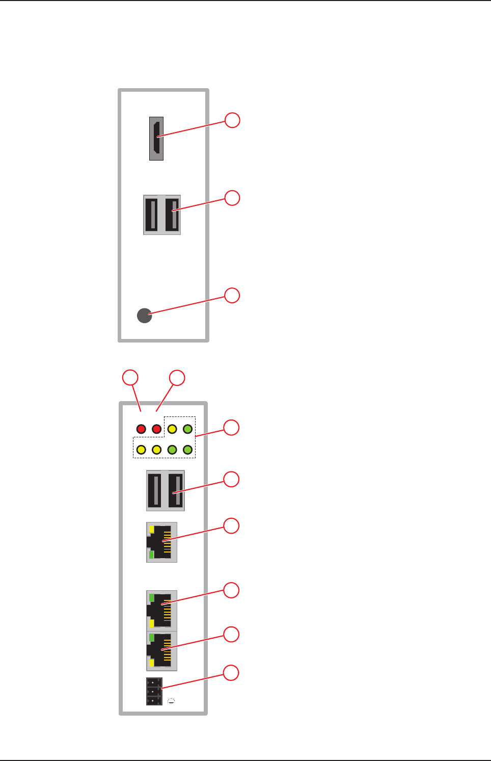
3.1 Positions of the interfaces
1
2
3
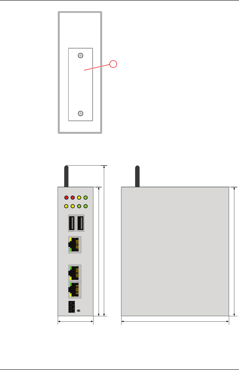
Figure1: NIOT-E-NPI3-51-EN-RE (Top view)
Fieldbus
ERR
NS 6
RUN
MS APL SYS
LED1 LED2 ACT POW
LINK
L/A
LINK
L/A
ACT
Rx/TX
ACT
Rx/TX
IN
CH0
OUT
CH1
--
+
7
8
9
10
11
5
4
Figure2: NIOT-E-NPI3-51-EN-RE (Front view)
netPI | NOIT-E-NPI3-51-EN-RE
DOC170801UM01EN | Revision 1 - Draft 1 | English | 2017-09 | Draft | Public
© Hilscher 2017
Device drawings 11/57
12
Figure3: NIOT-E-NPI3-51-EN-RE (Bottom view)
3.2 Dimensions
Fieldbus
ERR
NS
RUN
MS APL SYS
LED1 LED2 ACT POW
LINK
L/A
LINK
L/A
ACT
Rx/TX
ACT
Rx/TX
IN
CH0
OUT
CH1
--
+
120 mm
140 mm
40 mm
120 mm
100 mm
Figure4: Dimensions
netPI | NOIT-E-NPI3-51-EN-RE
DOC170801UM01EN | Revision 1 - Draft 1 | English | 2017-09 | Draft | Public
© Hilscher 2017

Connections and mounting 12/57
4 Connections and mounting
4.1 Mounting
Mount the Edge Gateway on a DIN rail onto the wall of the cabinet.
4.2 Power supply
DC 24V Pin Signal Description
- GND Ground (Reference potential)
+ +24 V DC +24 V DC
FE Functional earth
Table2: Power supply connector NIOT-E-TPI51-EN-RE
4.3 LAN connectors
The Edge Gateway has one LAN connector for connecting it to the cloud
network, positions (8) and (see section Positions of the
interfaces [}page10]).
The MAC addresses of the LAN interfaces are printed on the device label.
Section Configuring Ethernet communication (LAN) [}page35] describes,
how you can set the IP address parameters of the LAN interfaces.
4.4 Real-Time Ethernet connectors
The Edge Gateway has 2 RJ45-connectors to connect the fieldbus to a
Real-Time Ethernet network, positions (9) and (10) (see section Positions
of the interfaces [}page10]).
4.5 USB connectors
The Edge Gateway has 4 USB connectors (4 x USB 2.0), positions (2) and
(7) (see section Positions of the interfaces [}page10]). You do not need
the USB connectors for operation of the Edge Gateway. You need the USB
connector if you connect a keyboard in order to change settings in the
BIOS or if you do a firmware recovery with a USB stick.
4.6 Wi-Fi antennas
You can use the Edge Gateway for wireless network communication. The
Edge Gateway supports 2 Wi-Fi operating modes: Access Point and
Client. Operating mode Access Point allows the Edge Gateway to connect
to a mobile device in order to configure the Edge Gateway from a mobile
device.
Section WiFi describes how you activate the antennas and how to set the
Wi-Fi operating mode.
netPI | NOIT-E-NPI3-51-EN-RE
DOC170801UM01EN | Revision 1 - Draft 1 | English | 2017-09 | Draft | Public
© Hilscher 2017

Connections and mounting 13/57
4.7 HDMI connector
The Edge Gateway has an HDMI-connection for a monitor (position (1))
which is not required for the operation of the Edge Gateway.
netPI | NOIT-E-NPI3-51-EN-RE
DOC170801UM01EN | Revision 1 - Draft 1 | English | 2017-09 | Draft | Public
© Hilscher 2017
LEDs 14/57
5 LEDs
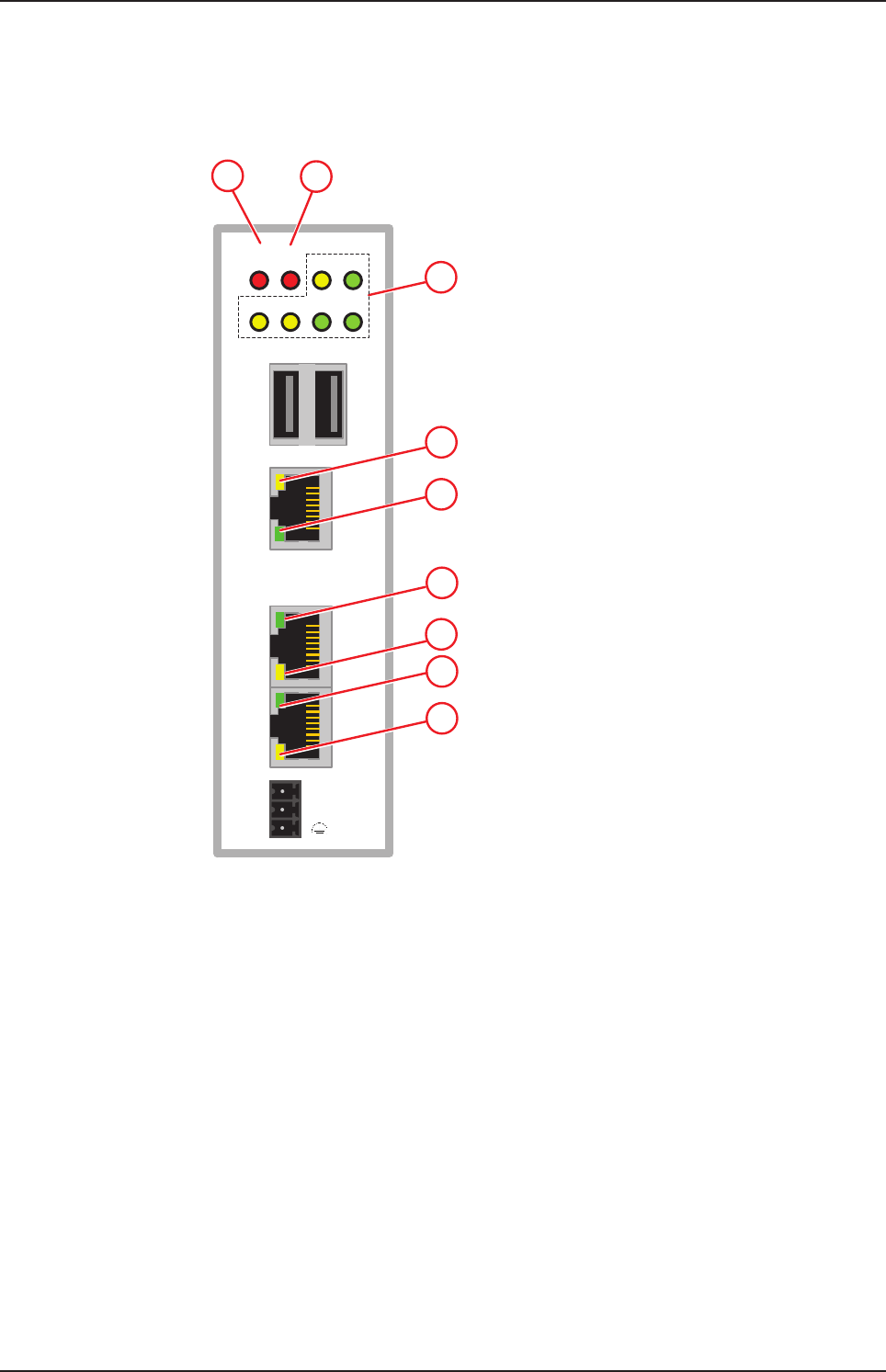
5.1 Positions of the LEDs on the gateway
Fieldbus
ERR
NS 3
RUN
MS APL SYS
LED1 LED2 ACT POW
LINK
L/A
LINK
L/A
ACT
Rx/TX
ACT
Rx/TX
IN
CH0
OUT
CH1
--
+
4
5
5
8
9
7
12
Figure5: NIOT-E-NPI3-51-EN-RE LED positions
netPI | NOIT-E-NPI3-51-EN-RE
DOC170801UM01EN | Revision 1 - Draft 1 | English | 2017-09 | Draft | Public
© Hilscher 2017
LEDs 15/57
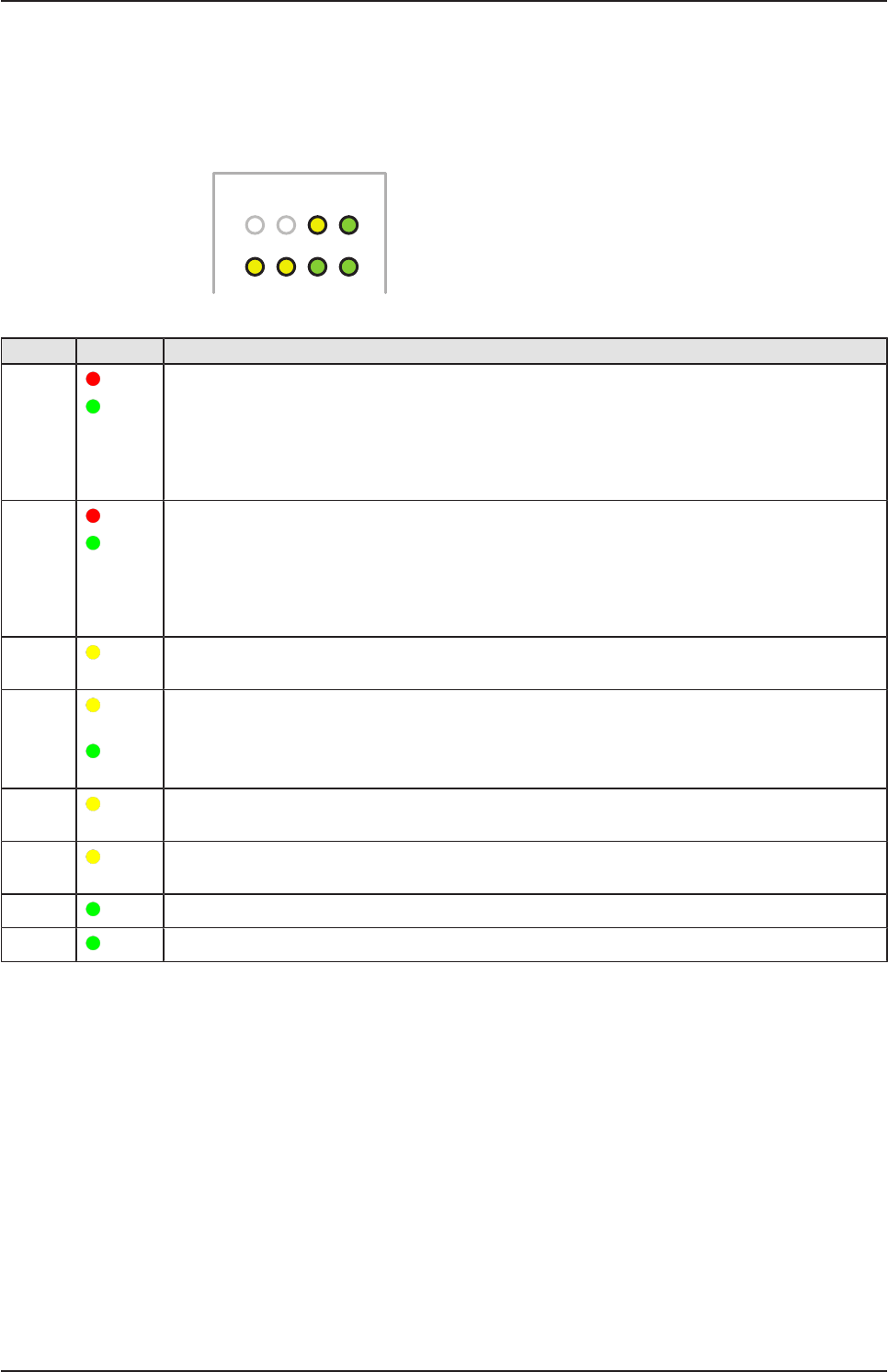
5.2 Gateway status LEDs
LEDs indicating communication status, system status, application status
and voltage supply. The position of the LEDs is indicated by position (3) in
section Positions of the LEDs on the gateway [}page14].
E
R
R
N
S
R
U
N
M
S
APL SYS
LED1 LED2 ACT POW
Figure6: Gateway state LEDs
LED Color Meaning
ERR
NS (red)/
(green)
LED communication status Real-Time-Ethernet.
Name and function depends on used RTE protocol:
PROFINET IO Device = ERR (Bus failure)
EtherNet/IP Adapter = NS(Network status) See section
See section LEDs of the PROFINET IO Device interface [}page16] and section LEDs of the
EtherNet/IP Adapter interface [}page17].
RUN
MS (red)/
(green)
LED communication status Real-Time-Ethernet.
Name and function depends on used RTE protocol:
PROFINET IO Device = RUN (System failure)
EtherNet/IP Adapter = MS (Module status)
See section LEDs of the PROFINET IO Device interface [}page16] and section LEDs of the
EtherNet/IP Adapter interface [}page17].
APL
( yellow)
Application status
SYS
(yellow)/
(green)
System status
LED1
( yellow)
GPIO12: can be programmed, currently not used.
LED2
(yellow)
GPIO13: can be programmed, currently not used.
ACT (green) Activity
POW (green) Voltage supply is OK
Table3: Description of gateway status LEDs
netPI | NOIT-E-NPI3-51-EN-RE
DOC170801UM01EN | Revision 1 - Draft 1 | English | 2017-09 | Draft | Public
© Hilscher 2017
LEDs 16/57
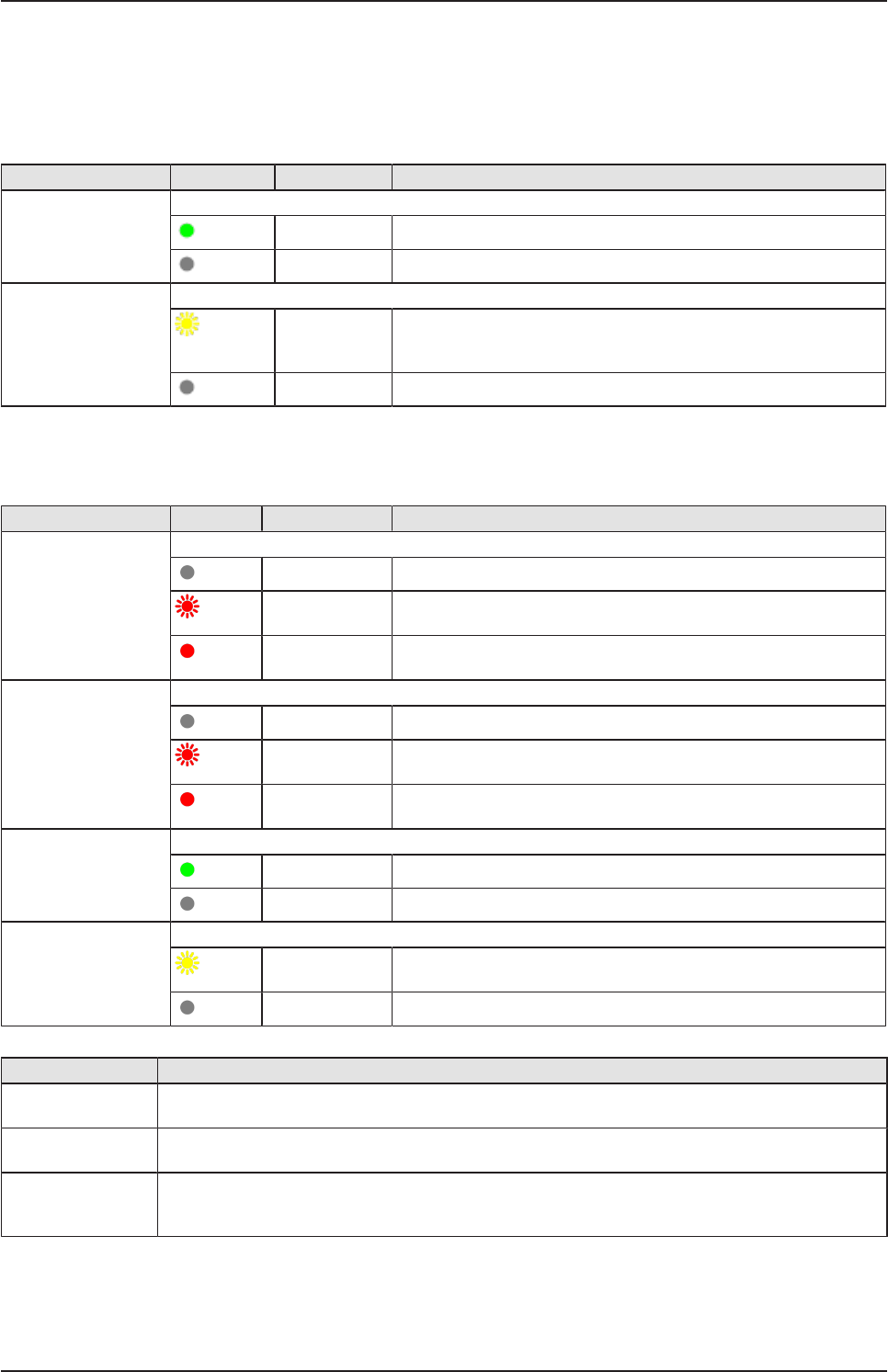
5.3 LEDs of the LAN interface
LEDs indicating state of the LAN communication. For the positions of the
LAN LEDs, see positions (2) and (3) in section Positions of the LEDs on the
gateway [}page14].
LED Color State Meaning
LINK
See position (3)
LED green
(green) On 100 MBit MBit network connection
(off) off 10 MBit or no network connection
RX/TX
See position (2)
LED yellow
(yellow) Flickering
(load
dependent)
The device sends/receives frames
(off) off The device does not send/receive frames.
Table4: LEDs LAN interface NIOT-E-TPI51-EN-RE
5.4 LEDs of the PROFINET IO Device interface
LED Color State Meaning
SF (System Failure)
Position in the device
drawing: (2)
Duo LED red/green
(off) (Off) No error
(red) Flashing
(1 Hz, 3 s)
DCP signal service is initiated via the bus.
(red) On Watchdog timeout; channel, generic or extended diagnosis
present; system error
BF (Bus Failure)
Position in the device
drawing: (1)
Duo LED red/green
(off) Off No error
(red) Flashing
(2 Hz)
No data exchange
(red) On No configuration;
or low speed physical link; or no physical link
LINK
CH0 (6) , CH1 (7)
LED green
(green) On The device is linked to the Ethernet.
(off) Off The device has no link to the Ethernet.
RX/TX
CH0 (8) , CH1 (9)
LED yellow
(yellow) Flickering (load
dependent)
The device sends/receives Ethernet frames.
(off) Off The device does not send/receive Ethernet frames.
Table5: LED states for the PROFINET IO-Device protocol
LED state Definition
Flashing
(1 Hz, 3 s)
The indicator turns on and off for 3 seconds with a frequency of 1 Hz:
“on” for 500 ms, followed by “off” for 500 ms.
Flashing
(2 Hz)
The indicator turns on and off with a frequency of 2 Hz:
“on” for 250 ms, followed by “off” for 250 ms.
Flickering (load
dependent)
The indicator turns on and off with a frequency of approximately 10 Hz to indicate high Ethernet
activity: "on" for approximately 50 ms, followed by "off" for 50 ms. The indicator turns on and off in
irregular intervals to indicate low Ethernet activity.
Table6: LED state definitions for the PROFINET IO-Device protocol
netPI | NOIT-E-NPI3-51-EN-RE
DOC170801UM01EN | Revision 1 - Draft 1 | English | 2017-09 | Draft | Public
© Hilscher 2017
LEDs 17/57
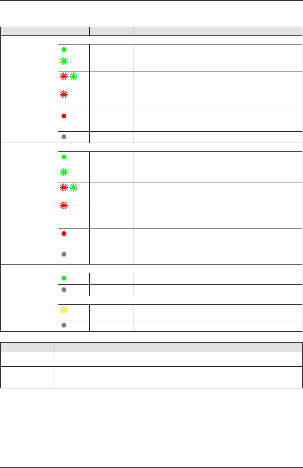
5.5 LEDs of the EtherNet/IP Adapter interface
LED Color State Meaning
MS
(module status)
Position in the device
drawing: (2)
Duo LED red/green
(green) On Device operational: The device is operating correctly.
(green) Flashing
(1 Hz)
Standby: The device has not been configured.
(red/green)
Flashing
(1 Hz)
Self-test:The device is performing its power up testing.
(red) Flashing
(1 Hz)
Minor fault: The device has detected a recoverable minor fault.
E. g. an incorrect or inconsistent configuration can be considered
as a minor fault.
(red) On Major fault: The device has detected a non-recoverable major
fault.
(off) Off No power: The power supply to the device is missing.
NS
(Network status)
Position in the device
drawing: (1)
Duo LED red/green
(green) On Connected: The device has at least one established connection
(even to the Message Router).
(green) Flashing
(1 Hz)
No connections:The device has no established connections, but
has obtained an IP address.
(red/green)
Flashing
(1 Hz)
Self-test:The device is performing its power up testing.
(red) Flashing
(1 Hz)
Connection timeout: One or more of the connections in which
this device is the target have timed out. This status will be finished
only if all timed out connections are reestablished or if the device
is reset.
(red) On Duplicate IP: The device has detected that its IP address is
already in use.
(off) (Off) Not powered, no IP address:The device does not have an IP
address (or is powered off).
LINK
CH0 (6) , CH1 (7)
LED green
(green) On The device is linked to the Ethernet.
(off) Off The device has no link to the Ethernet.
ACT
CH0 (8) , CH1 (9)
LED yellow
(yellow) Flickering (load
dependent)
The device sends/receives Ethernet frames.
(off) Off The device does not send/receive Ethernet frames.
Table7: LED states for the EtherNet/IP Adapter protocol
LED state Definition
Flashing (1 Hz) The indicator turns on and off with a frequency of 1 Hz:
“on” for 500 ms, followed by “off” for 500 ms.
Flickering (load
dependent)
The indicator turns on and off with a frequency of approximately 10 Hz to indicate high Ethernet
activity: on for approximately 50 ms, followed by off for 50 ms. The indicator turns on and off in
irregular intervals to indicate low Ethernet activity
Table8: LED state definitions for the EtherNet/IP Adapter protocol
netPI | NOIT-E-NPI3-51-EN-RE
DOC170801UM01EN | Revision 1 - Draft 1 | English | 2017-09 | Draft | Public
© Hilscher 2017

Commissioning the Edge Gateway 18/57
6 Commissioning the Edge Gateway
6.1 Establishing the IP address communication
An IP address is required to address the Edge Gateway in the LAN
network.
The following figure shows the factory setting of the LAN interfaces and the
assignment of the connections.
6.2 Using the web browser to establish a connection with the
Edge Gateway
You have three possibilities to access the Edge Gateway:
1. by means of the host name (see section Using the host
name [}page18])
2. by access via the Windows network (see section Access to the Edge
Gateway in the Windows network environment [}page19]),
3. by using the IP address (see section Using the IP address).
6.2.1 Using the host name
The Edge Gateway has a host name you can use to access the device.
Where do you find the host name on the device?
The device is delivered (factory setting) with a label printed at its bottom. In
the figure below the host name has a red frame.
Establishing a connection with the host name
ØEnter the following address in the address line of your browser:
https://<hostname>
Example: For the device with the host name NT0002A233E559 enter
https://NT0002A233E559
ðThe Edge Gateway Manager opens.
You can now use the Edge Gateway manager to configure the device. For
this purpose, read section Edge Gateway manager web page [}page21].
netPI | NOIT-E-NPI3-51-EN-RE
DOC170801UM01EN | Revision 1 - Draft 1 | English | 2017-09 | Draft | Public
© Hilscher 2017
Commissioning the Edge Gateway 19/57
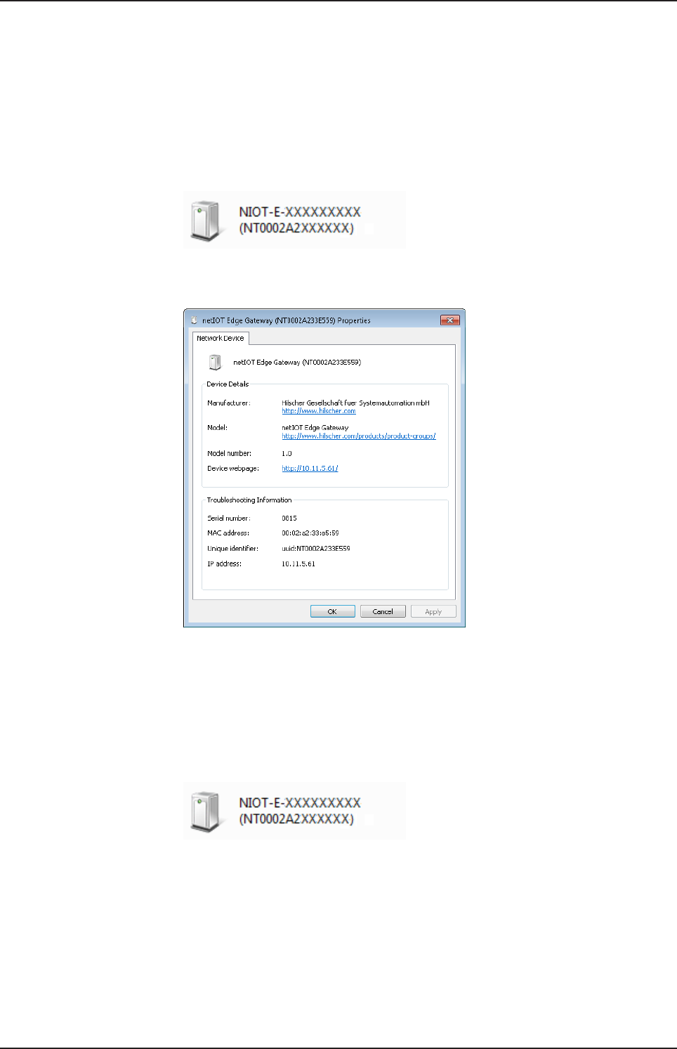
6.2.2 Access to the Edge Gateway in the Windows network environment
To be located easily in the network, the Edge Gateway uses the UPnP
technology (Universal Plug and Play). This technology will display the Edge
Gateway in the Windows network environment.
ØTo display all devices in the network, click on Network in the Windows
Explorer.
ÊYou will find the Edge Gateway under Other Devices:
Figure7: netIOT Edge Gateway in the Windows network
ØOpen the context menu of this entry and select Properties.
Figure8: Properties of the Edge Gateway
ÊThe menu provides information on the Edge Gateway, e.g. serial
number, MAC address, host name or die IP address.
ØClick on the link under Device web page.
ðThe Edge Gateway manager opens.
ØTo open the Edge Gateway manager, you can also double-click on the
device icon.
ðThe Edge Gateway manager opens.
You can now use the Edge Gateway manager to configure the device. For
this purpose, read section Edge Gateway manager web page [}page21].
netPI | NOIT-E-NPI3-51-EN-RE
DOC170801UM01EN | Revision 1 - Draft 1 | English | 2017-09 | Draft | Public
© Hilscher 2017
Edge Gateway manager 20/57
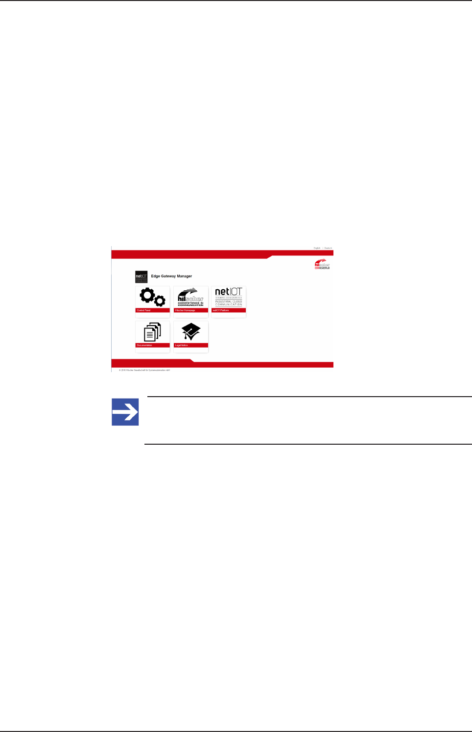
7 Edge Gateway manager
7.1 Calling the Edge Gateway Manager
The Edge Gateway manager is a web page with tiles that allow rapid
access to the applications integrated in the device or to external web
pages.
The Edge Gateway uses the secured HTTPS protocol to access web pages
stored in the Edge Gateway.
ØTo open the Edge Gateway manager, enter the following information in
the address line of your browser:
https://<Host name of the Edge Gateway>
or
https://<IP address of the Edge Gateway>
ðYour browser displays the Edge Gateway manager.
Figure9: Edge Gateway Manager
Note:
Remember that the secured HTTPS protocol is used here, not the
widely spread HTTP protocol.
netPI | NOIT-E-NPI3-51-EN-RE
DOC170801UM01EN | Revision 1 - Draft 1 | English | 2017-09 | Draft | Public
© Hilscher 2017
Edge Gateway manager 21/57
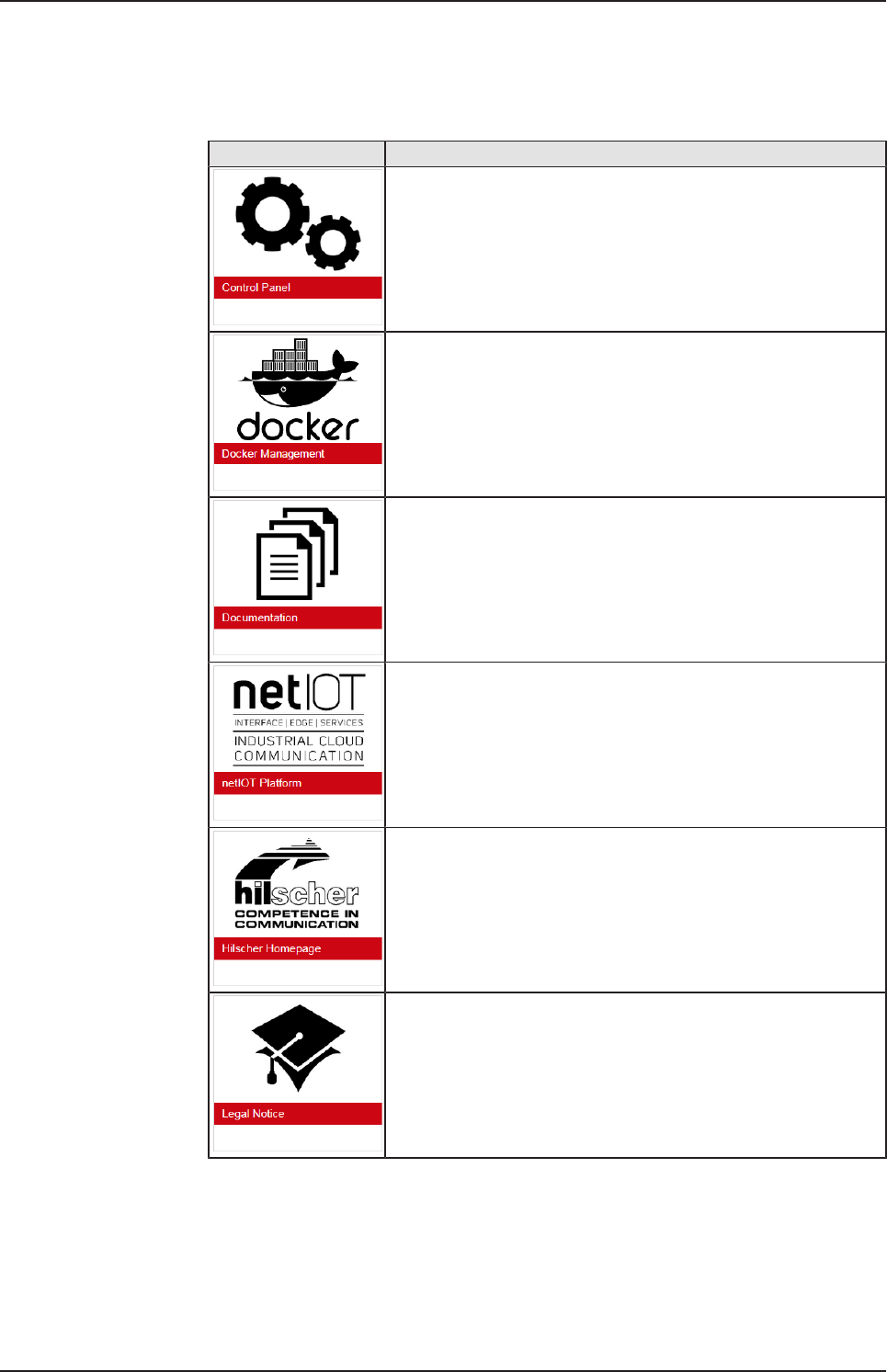
7.2 Edge Gateway manager web page
The Edge Gateway manager displays tiles that allow rapid access to the
applications integrated in the device or external web pages.
Icon Function
Opens the control panel of the Edge Gateway.
The control panel configures the Edge Gateway and displays
information on the system. Section Control Panel [}page22]
describes the possibilities of configuration as well as the displayed
information on the system.
Opens the Docker management.
See section Isolated application execution with
Docker [}page48].
Opens the Edge Gateway documentation stored in the device.
Opens the homepage of the netIOT platform in the Internet.
Requires a connection to the Internet.
Opens the Hilscher homepage in the Internet.
Requires a connection to the Internet.
Opens legal information concerning the Edge Gateway.
Requires a connection to the Internet.
Table9: Starting applications with the Edge Gateway manager
netPI | NOIT-E-NPI3-51-EN-RE
DOC170801UM01EN | Revision 1 - Draft 1 | English | 2017-09 | Draft | Public
© Hilscher 2017
Control Panel 22/57
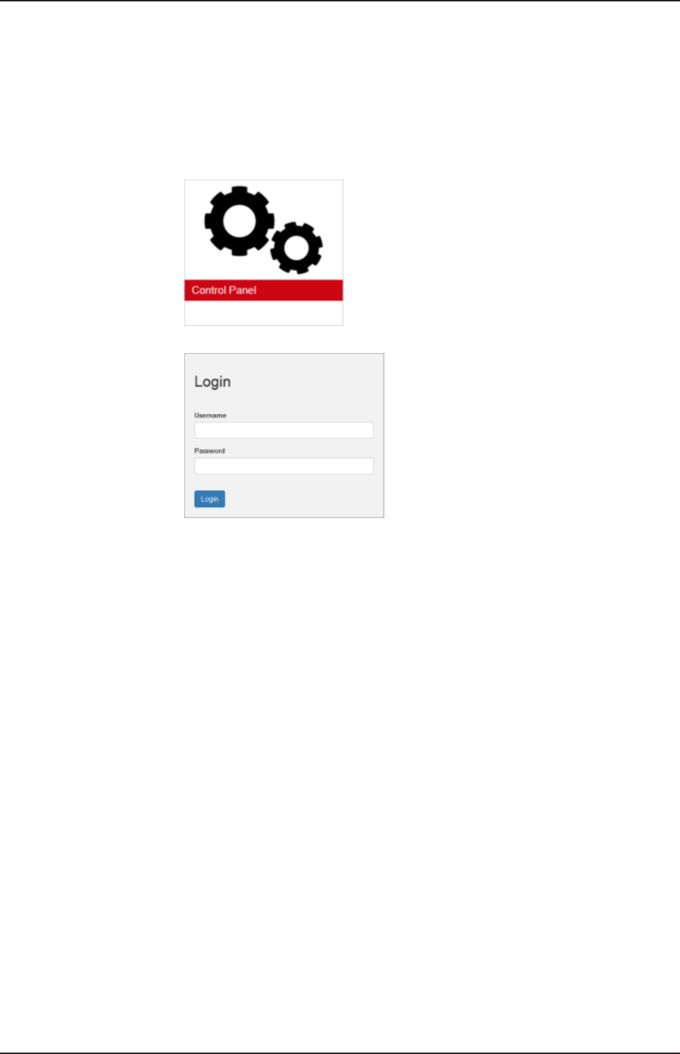
8 Control Panel
8.1 Opening the control panel
With the control panel you can configure the Edge Gateway and display
device-specific information.
ØClick the tile Control Panel.
ØThe login screen for the Control Panel is displayed.
ØEnter your user name and your password.
ØClick at Login.
ðThe Control Panel will be displayed.
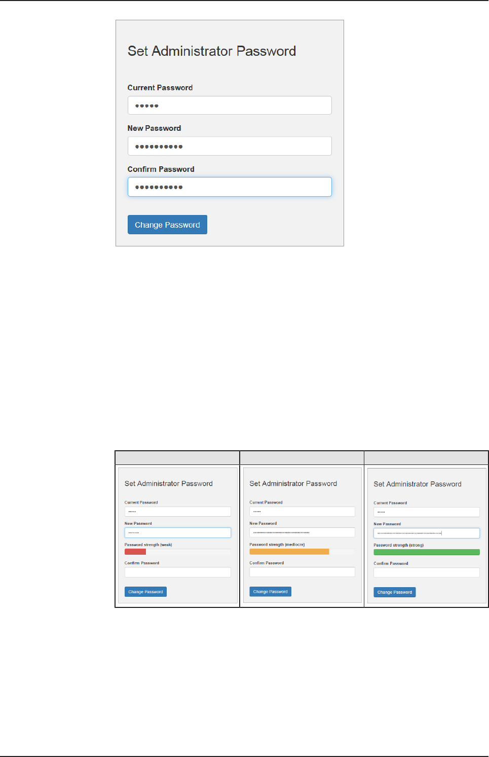
8.1.1 First login
Setting the administrator password when the control panel is called
for the first time
The dialog box Set Administrator Password is displayed when the control
panel is called for the first time.
netPI | NOIT-E-NPI3-51-EN-RE
DOC170801UM01EN | Revision 1 - Draft 1 | English | 2017-09 | Draft | Public
© Hilscher 2017
Control Panel 23/57
Figure10: Edge Gateway Manager - Setting the administrator password
To set a new administrator password, proceed as follows:
ØEnter the preset password under Current Password. With the first
commissioning, the password is:
admin
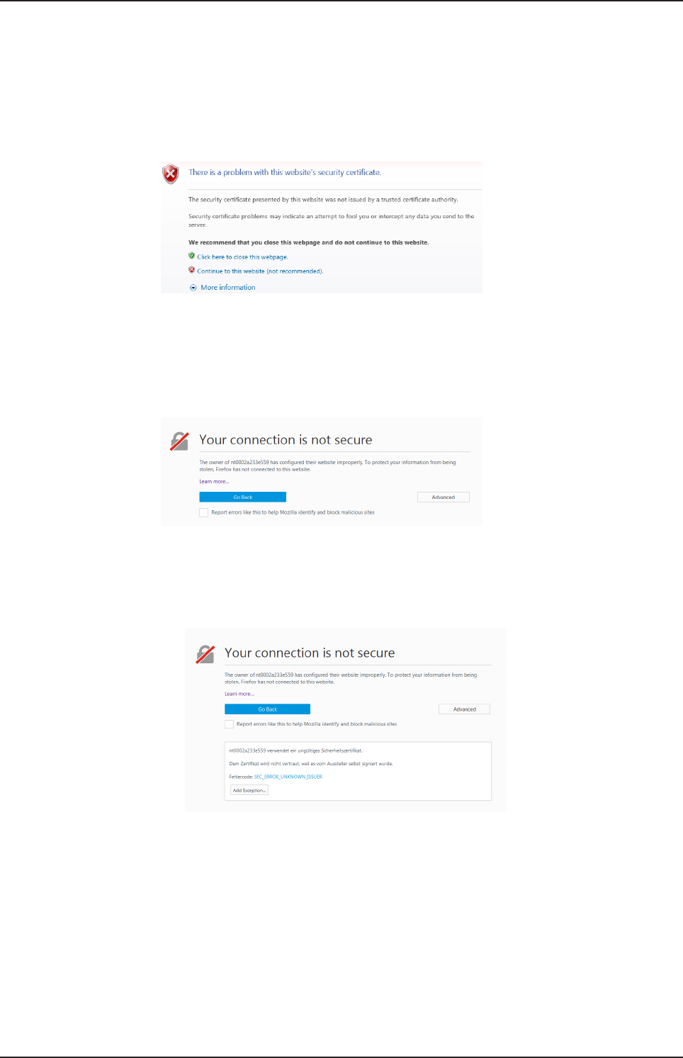
ØNow enter the new administrator password. The minimum allowed
length of the administrator password amounts to 7 characters. For
reasons of safety, Hilscher recommends using considerably more
characters. A strong password should contain small and capital letters
as well as numbers and special characters. In the dialog window
additionally a password quality indicator is displayed. The window
changes as follows depending on the quality of the specified password
with respect to its safety level (weak, mediocre or strong): Weak
password
Weak password Mediocre password Strong password
ØIf the specified password is indicated to be strong (display bar appears
in green), click at .
ðThus, the new administrator password for the user account Admin is
set.
netPI | NOIT-E-NPI3-51-EN-RE
DOC170801UM01EN | Revision 1 - Draft 1 | English | 2017-09 | Draft | Public
© Hilscher 2017

Control Panel 24/57
ðNow, you can work with the control panel as an administrator, you can
create further users in the user management, and assign access rights.
With the specified password you can work with the control panel as
administrator.
Also see about this
2User management [}40]
8.1.2 Secure connection
Edge Gateways support web connections secured by SSH/TSL via
https:// accesses only.
By definition, a secure connection can provide an efficient protection only if
a certificate proves that the server is secure. Only then can running
transactions of the initiating browser and the server be considered as
protected against interception and data theft.
This is why the browser at first inquires a certificate of verification from the
server (Gateway). This certificate proves that the issuer has verified the
security of the server. Each browser provides a preinstalled list of known
authorized issuers of certificates.
Each time the certificate of the server arrives at the browser, the browser
compares the issuer of the certificate with the issuers stored in the list of
known authorized issuers of certificates.
If the issuer of the certificate is not listed, the browser will signal a
certificate error and request the user's confirmation to continue because it
assumes that the connection is insecure.
As standard, Edge Gateways contain a certificate issued by Hilscher that is
not on the list of the known authorized issuers of certificates. Due to that,
the browser signals an insecure connection and requests the confirmation
to continue. When this confirmation has been given once, any future
connections will be established without further requests.
Note:
In the control panel you can replace this certificate any time by the
certificate of a known authorized issuer of certificates, see section
Uploading and installing own security certificates [}page43]).
netPI | NOIT-E-NPI3-51-EN-RE
DOC170801UM01EN | Revision 1 - Draft 1 | English | 2017-09 | Draft | Public
© Hilscher 2017
Control Panel 25/57
8.1.2.1 Connection without certificate with Microsoft Internet Explorer
Microsoft Internet Explorer: Edge Gateway Manager will not be
displayed
If you use the Microsoft Internet Explorer and the following page is
displayed, click the option Continue to this web site (not recommended).
Figure11: Security error message of the Internet Explorer
8.1.2.2 Connection without certificate with Firefox
If you use Firefox as a browser, a self-signed certificate will cause the
following error message:
Figure12: Security error message of the Firefox browser (1)
To avoid this message caused by a self-signed certificate, proceed as
follows:
ØTo display the complete message, click Advanced.
Figure13: Security error message of the Firefox browser (2)
ØTo define an exceptional rule that enables the display of the user
interface without repeated error messages, click Add Exception.
netPI | NOIT-E-NPI3-51-EN-RE
DOC170801UM01EN | Revision 1 - Draft 1 | English | 2017-09 | Draft | Public
© Hilscher 2017
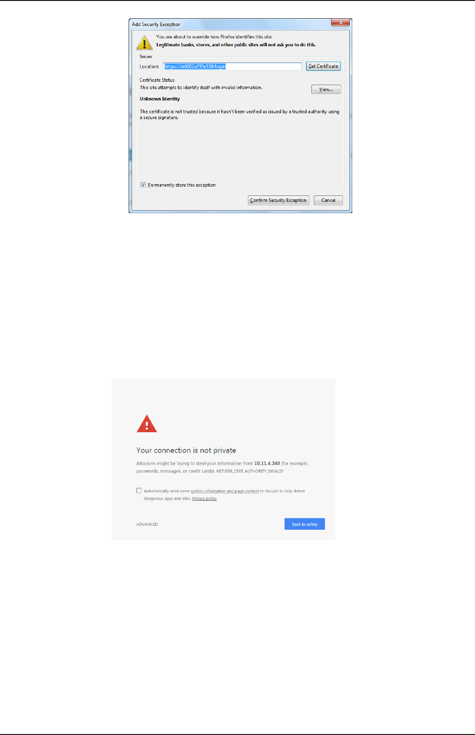
Control Panel 26/57
Figure14: Firefox dialog box: Adding exceptional safety rule
ØTo save the setting permanently, check the box Permanently store
this exception.
ØTo save the rule, click Confirm Security Exception.
ðWhen you open the control panel in future, security messages will no
longer be displayed.
8.1.2.3 Connection without certificate with Google Chrome
If you use Google Chrome as web browser, you will get the following error
message due to a self-signed certificate.
Figure15: Security error message of Google Chrome (1)
Proceed as follows in order to avoid the following message, which is
caused by a self-signed certificate,
ØClick at ADVANCED to display the complete message.
netPI | NOIT-E-NPI3-51-EN-RE
DOC170801UM01EN | Revision 1 - Draft 1 | English | 2017-09 | Draft | Public
© Hilscher 2017

Control Panel 27/57
Figure16: Security error message of Google Chrome (2)
ØIn order to continue, click at Proceed to ... (unsafe).
ðThe Control Panel is displayed.
netPI | NOIT-E-NPI3-51-EN-RE
DOC170801UM01EN | Revision 1 - Draft 1 | English | 2017-09 | Draft | Public
© Hilscher 2017

Control Panel 28/57
8.2 Control Panel commands
8.2.1 Overview and main menu
The following figure displays the main menu of the Control Panel.
Figure17: Main menu of the Control Panel
Menu Submenu Description Details in section
System Info Center Displaying the system information, monitoring of
the processor core temperature, and a system
monitor for the usage of CPU, main memory,
and SSD
Displaying system
information [}page29]
Time Settings of system time and time
synchronization.
Setting the system
time [}page30]
Reboot Rebooting the Linux operating system of the
Edge Gateway
Rebooting the
system [}page32]
Shutdown Shutting down the Linux operating system of the
Edge Gateway
System shutdown [}page32]
Package
Manager
Packages Managing the packages of the Linux-based
operating system of the Edge Gateway.
Packet management [}page33]
Network LAN Configuring the Ethernet interfaces to the field or
cloud.
Configuring Ethernet
communication
(LAN) [}page35]
WiFi Configuring the WiFi communication WiFi
Hostname Displaying and configuring the host name
identifying the Edge Gateway in the network.
Hostname [}page36]
Services Service List Displaying, starting, and stopping the services of
the Edge Gateway.
Services [}page37]
User
Management
Roles Displaying and configuring the permissions for
user roles.
Managing user roles [}page40]
Accounts Displaying user accounts und assigning user
roles.
Managing user
accounts [}page42]
Security SSL Certificate Installing the SSL safety certificate. Security certificates [}page42]
Help Info Displaying current software version. Help [}page46]
Session User Profile Displaying the permissions of the user. User profile [}page46]
Logout Logout Logout [}page47]
Table10: Functional overview of the Control Panel
For the pages which can be invoked via the Control Panel, the following
applies:
If for the selected page, no access right for reading is present, this has the
following implications:
·No data are displayed. All important controls and displays of the page
are grayed out respectively inactive.
·The error message Permission denied is displayed when accessing
the page.
If there is read but no write access right present, this has the following
implications:
netPI | NOIT-E-NPI3-51-EN-RE
DOC170801UM01EN | Revision 1 - Draft 1 | English | 2017-09 | Draft | Public
© Hilscher 2017

Control Panel 29/57
·The error message Permission denied is displayed when trying to
make a change.
8.2.2 System information and system time
8.2.2.1 Displaying system information
Open this page with System > Info Center. No access rights are required
in order to open this page. This page shows e.g. the firmware version and
the serial number of the Edge Gateway.
Figure18: Page Info Center
The Info Center displays the following information:
System info Description
Hardware ident. Serial number of the Edge Gateway
Model name Model designation of the Edge Gateway (NIOT-E-NPI3-51-RE-EN)
Firmware version Complete version designation of the firmware stored in the Edge
Gateway
System time Synchronization status of the internal clock of the Edge Gateway.
When the clock is synchronized via the network, the IP address and
the name of the time server used for synchronization will be
displayed. The user has to configure the time zone.
Processor name Name of the microprocessor (CPU) installed in the Edge Gateway.
Table11: Info Center: Area System info
Monitoring Description
CPU usage Number of microprocessor cores plus clock frequency and average
utilization of each core in the Edge Gateway
Memory utilization Size and average utilization of the main memory in the Edge Gateway
Storage space Display of available memory and the memory that is currently utilized
on the integrated Solid-State-Disk of the Edge Gateway
Table12: Info Center: Area Monitoring
netPI | NOIT-E-NPI3-51-EN-RE
DOC170801UM01EN | Revision 1 - Draft 1 | English | 2017-09 | Draft | Public
© Hilscher 2017
Control Panel 30/57
Temperature Description
CPU temperature Display of the temperature of each processor core in the Edge
Gateway
Table13: Info Center: Area Temperature
If the data of the area Monitoring cannot be read, this is grayed out.
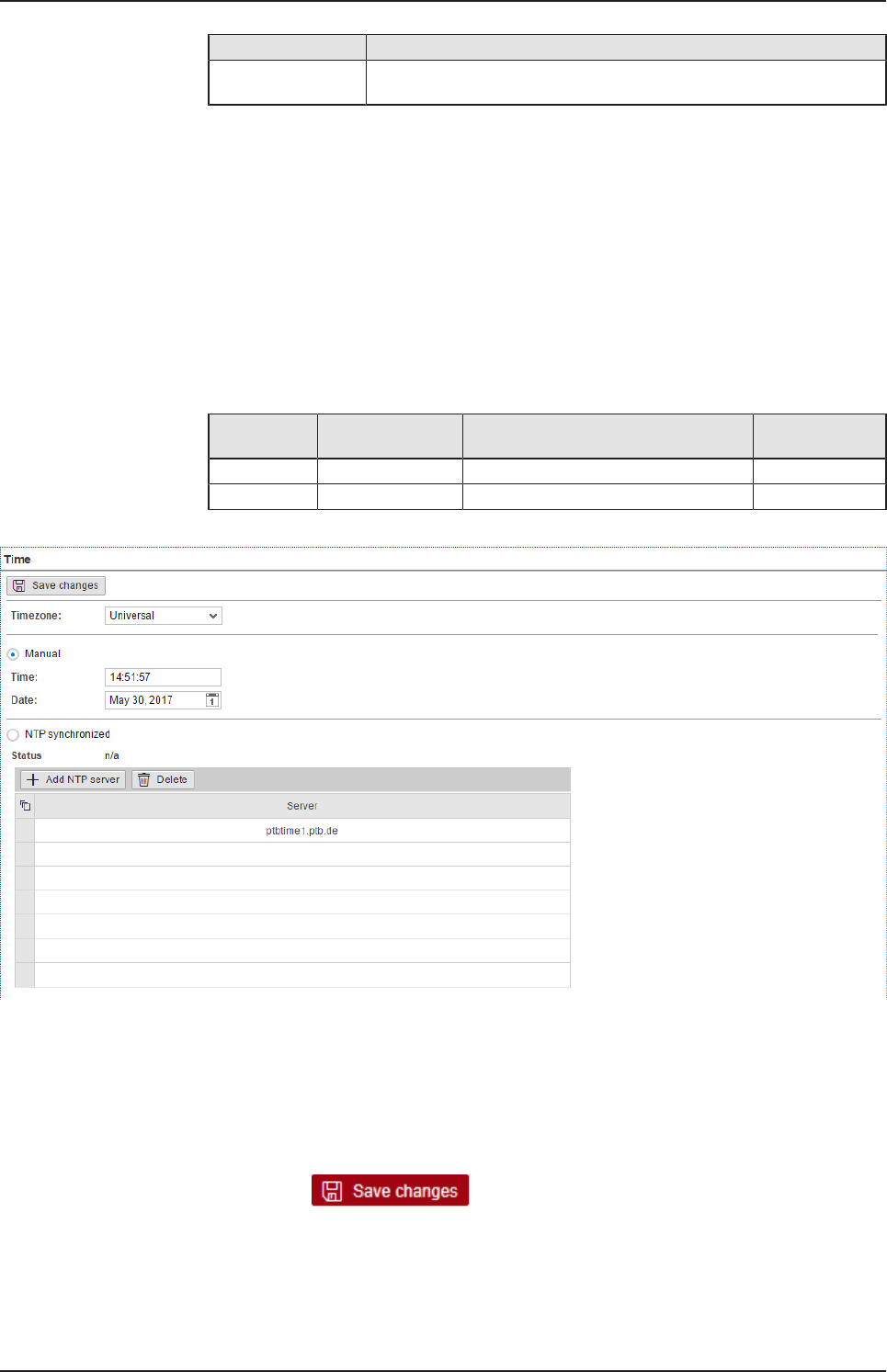
8.2.2.2 Setting the system time
Open this page with System > Time.
In order to access this page you require the following access right:
Setting the system time
On this page, you can set the system time and the time zone this time
relates to. You can set the system time in two ways:
Type Selection Method Standard
presetting
manually Manual selection by entering date and time yes
automatically NTP synchronized by means of a time server no.
Table14: Setting the system time
Figure19: Time configuration page
Setting the system time manually
ØClick the option Manual.
ØEnter the time in the input field Time in the format hh:mm:ss.
ØSet the date using the calendar input field Date.
ØClick at .
ðThe system time is set.
netPI | NOIT-E-NPI3-51-EN-RE
DOC170801UM01EN | Revision 1 - Draft 1 | English | 2017-09 | Draft | Public
© Hilscher 2017
Control Panel 31/57
Setting the system time automatically using a time server
You can synchronize the time using a time server that uses the Network
Time Protocol (NTP). Under NTP synchronized there is a list where you
can enter such time servers. The list of NTP servers will be worked off from
top to bottom until a server gives a valid answer and synchronization
occurs.
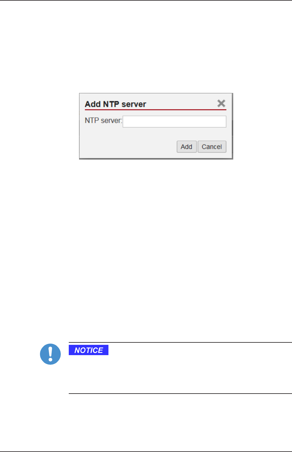
ØClick the option NTP Synchronized.
ØClick Add NTP server.
ÊThe dialog box for entering the NTP server is displayed.
ØIn the input field NTP server enter the address of a server which uses
the NTP to synchronize the time:
E.g.: To add the server for time synchronization of the Physikalisch-
Technische Bundesanstalt (the National Metrology Institute of
Germany) to the list, enter the address ptbtime1.ptb.de in the input
field NTP server.
ØClick Add.
ðThe system time is set via the NTP. As soon as the system time is set
successfully, the following information will be displayed under Status:
Synchronized to time server <IP address of the time
server>:<Port number of the time server > (<NTP
address of the time server>)
Setting the time zone
With the selection list Timezone you can adjust the time zone to your local
time in which the Edge Gateway is so that the set time can be interpreted
correctly (e.g. summer time conversion). For this purpose, the selection list
Timezone offers many setting options. The default value is Universal. For
Central European Time set CET.
Take care of the following notes:
Effects of setting the system time
Once the system has been set, system services and Node-RED flows,
which use the system time for synchronization, lose their reference time,
i.e. they refer to the new time set.
netPI | NOIT-E-NPI3-51-EN-RE
DOC170801UM01EN | Revision 1 - Draft 1 | English | 2017-09 | Draft | Public
© Hilscher 2017
Control Panel 32/57
Note:
For information on the NTP, see Wikipedia under https://
en.wikipedia.org/wiki/Network_Time_Protocol (English) or https://
de.wikipedia.org/wiki/Network_Time_Protocol (German). There you
will also find links to lists of NTP servers for various countries.
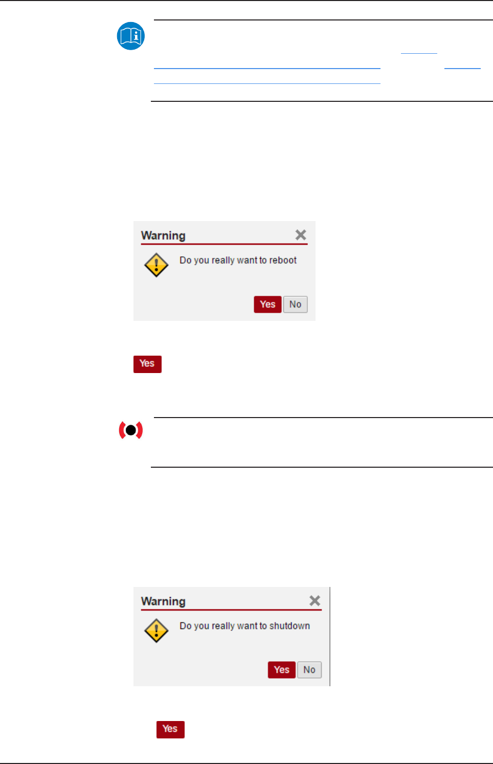
8.2.2.3 Rebooting the system
You have to login as Administrator to use this function.
In order to reboot the system:
ØWithin the Control Panel select menu entry System>Reboot
ÊThe following safety query is displayed:
Figure20: Reboot safety query
ØIf you really intend to reboot the system, answer to the safety query with
.
ðThe Linux operating system of your Edge Gateway is shut down and
then immediately restarted.
Note:
Take care of the consequences of shutting down and restarting for
your network, if you reboot the Edge Gateway.
8.2.2.4 System shutdown
You have to login as Administrator to use this function.
In order to shut down the system:
ØWithin the Control Panel select menu entry System>Shutdown.
ÊThe following safety query is displayed:
Figure21: Warning for consequences of shutdown
ØIf you really intend to shut down the system, answer to the safety query
with .
netPI | NOIT-E-NPI3-51-EN-RE
DOC170801UM01EN | Revision 1 - Draft 1 | English | 2017-09 | Draft | Public
© Hilscher 2017
Control Panel 33/57
ðThe Linux operating system of your Edge Gateway is shut down.
Note:
Take care of the consequences for your network, if you shut down
the Edge Gateway.
8.2.3 Packet management
8.2.3.1 Managing packets
Open this page with Package Manager > Packages.
In order to access this page you require the following access right:
Managing packets
This page contains the package management of the Linux-based operating
system of the Edge Gateway. This page
·lists the installed packages including version,
·adds new packages or
·updates already installed packages.
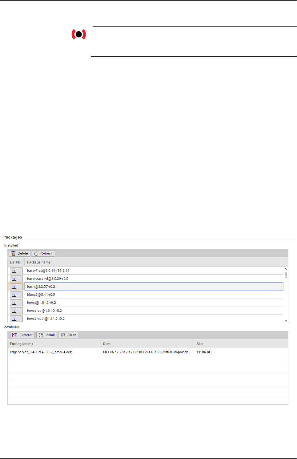
Table of installed packages
The area Packages of the table Installed shows you the list of the installed
packages.
Figure22: Packages installed
Each line of the list of the installed packages contains the name and
version of a package. To display a summary of the contents of a package,
click the button Details.
netPI | NOIT-E-NPI3-51-EN-RE
DOC170801UM01EN | Revision 1 - Draft 1 | English | 2017-09 | Draft | Public
© Hilscher 2017
Control Panel 34/57
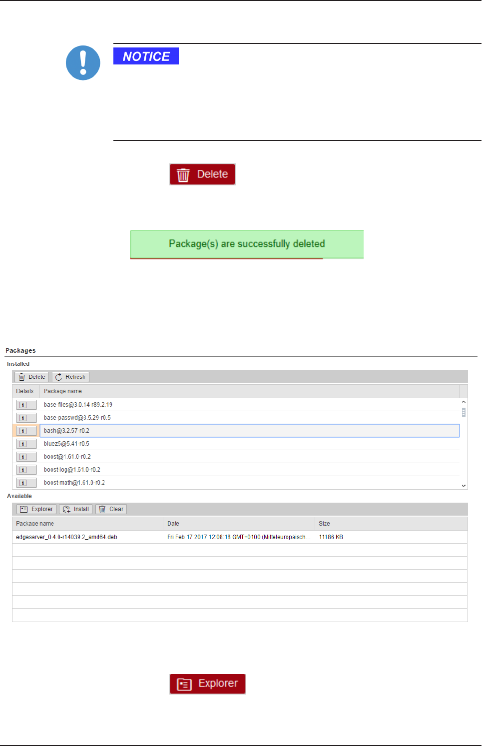
Deleting packages from the list of available packages
Risk of losing the data and the operational safety of the Edge Gateway
Delete packages only if you have profound knowledge of the operating
system LINUX and if you are absolutely sure that the package in question
can be deleted without any risk for the function of the Edge Gateway and its
operating system.
ØSelect the package to be deleted in table Installed.
ØClick at .
ðThe package is deleted from the Edge Gateway’s file system. If the
package file could be successfully deleted, the following message box
is displayed:
Table of available but not yet installed packages
The table Available displays the packages that are available for installation,
but which are not yet installed. You first have to select and add the
packages to be installed.
Figure23: Table of the packages that are available for installation
Selecting and installing the package file
ØClick at .
ÊA dialog for file selection is displayed.
netPI | NOIT-E-NPI3-51-EN-RE
DOC170801UM01EN | Revision 1 - Draft 1 | English | 2017-09 | Draft | Public
© Hilscher 2017
Control Panel 35/57
ØSelect the package file to be loaded. Debian package files have the
ending *.deb.
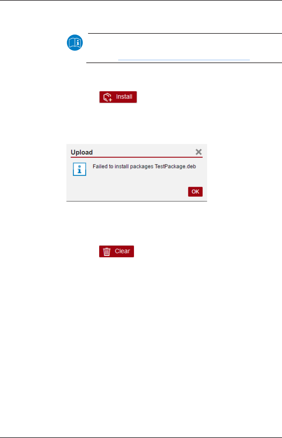
Note:
You can find more information on the Debian packet file format in
English at https://en.wikipedia.org/wiki/Deb_(file_format).
ðThe package within the selected file is checked for correctness. If the
Edge Gateway accepts the package, the name, creation date, and file
size of the package will be displayed in a line of the table Available.
ØClick at .
ðIf the Edge Gateway accepts the file, it will be installed, removed from
the table Available, and displayed in the table Installed.
ðIf the package cannot be installed, the message dialog Upload - Failed
to install... appears.
Figure24: Message box "Upload - Failed to install packages..."
Delete package file from list of available but not yet installed files
ØSelect the package file to be deleted. Package files have the
ending .deb.
ØClick at .
ðThe line containing the package file to be deleted is removed from the
list of available but not yet installed files.
8.2.4 Network
8.2.4.1 Configuring Ethernet communication (LAN)
Open this page with Network > LAN.
In order to access this page you require the following access right:
Access to LAN (Ethernet network)
On this page you configure the Ethernet interfaces eth0, eth1 (both on
the side of the cloud) and cifx0 (on the side of the fieldbus). For each
Ethernet interface you can configure how to set the IP address:
·The Edge Gateway is to obtain the IP address parameters automatically
from a DHCP server: Option DHCP.
·The IP address parameters are manually entered by the user: Option
Fixed address.
netPI | NOIT-E-NPI3-51-EN-RE
DOC170801UM01EN | Revision 1 - Draft 1 | English | 2017-09 | Draft | Public
© Hilscher 2017
Control Panel 36/57
The IP address parameters include the IP address, the subnet mask, the
Gateway address, and the IP addresses of the 1st and 2nd domain name
server.
The default IP address of the LAN connection port 2 is 192.168.253.1
with the subnet mask 255.255.255.0.
Column Meaning
Name displays the name of the LAN interface.
MAC address displays the MAC address of the LAN interface.
Settings Selecting the configuration method: Here you can select between
·DHCP (IP address parameters automatically obtained from a DHCP
server) or
·Fixed address (IP address parameters entered by the user)
If you enter the IP address manually, also always enter the subnet
mask and the Gateway address.
Domain Name
System
If you enter the IP address parameters manually, enter the IP address
of the 1st and 2nd domain name server.
Table15: Table LAN: Meaning of the columns
If you want to permanently save the changes you made, click at
afterwards.
8.2.4.2 Hostname
Open this page with Network > Hostname.
In order to access this page you require the following access right:
Access to hostname of Edge Gateway
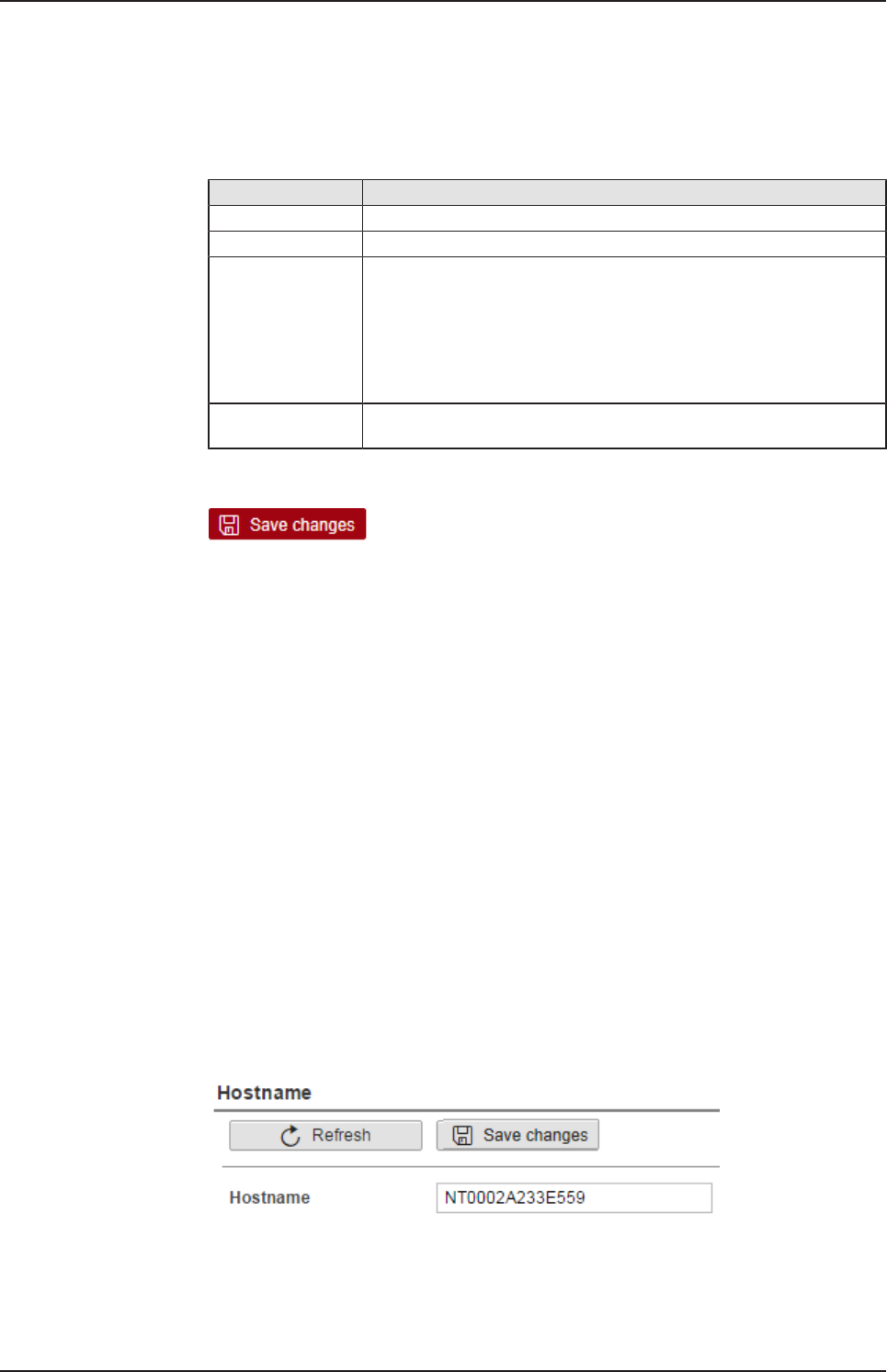
On this page you configure the host name.
The host name identifies the device via the WiFi or LAN network.
The default host name starts with the two letters "NT" followed by the LAN
MAC address of the LAN connection port 1 of the Edge Gateway. Example
NT0002A233E559. The default host name is printed on the label at the
bottom of the Edge Gateway. With the host name you can access the Edge
Gateway from your PC even without knowing the IP address of the Edge
Gateway (also see Using the web browser to establish a connection with
the Edge Gateway [}page18]).
If the Edge Gateway does not obtain an IP address from a DHCP server,
the system cannot translate the host name and you cannot access the
device.
Figure25: Hostname
netPI | NOIT-E-NPI3-51-EN-RE
DOC170801UM01EN | Revision 1 - Draft 1 | English | 2017-09 | Draft | Public
© Hilscher 2017
Control Panel 37/57
Input field Hostname
In order to specify the hostname, enter a string with arbitrary length
consisting of ASCII characters into the input field Hostname.
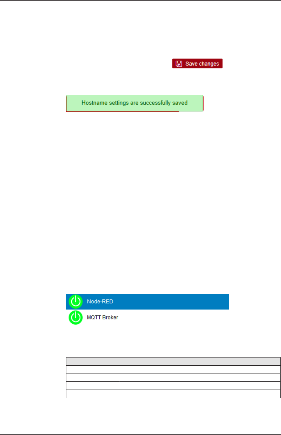
Saving the host name
The hostname is saved by clicking at .
If storing the hostname has succeeded, the following message box is
displayed:
8.2.5 Services
8.2.5.1 Starting, stopping and configuring services
Open this page with Services > Service List.
In order to access this page you require the following access right:
Configure Node-RED
Configure MQTT Broker
On this page you can
·display the list of the running services,
·display the operating status of each service,
·stop and start individual services,
·activate/deactivate Autostart, and
·download, upload and delete the flow of the Node-RED service.
The list of services is displayed at the left edge:
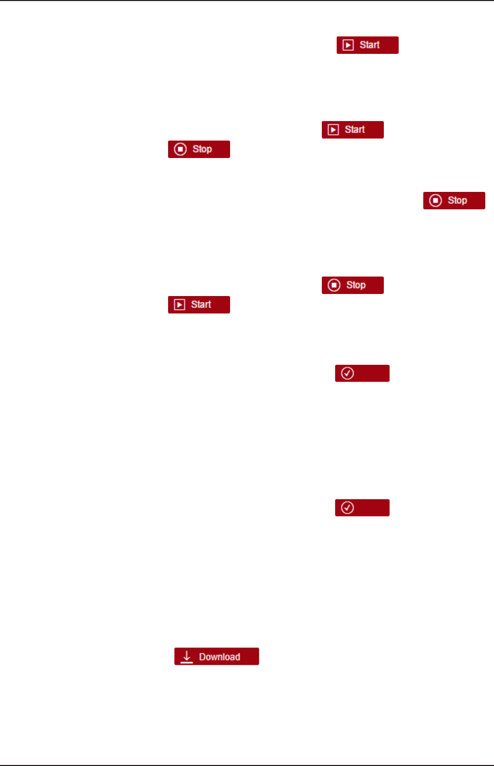
Figure26: List of default services
For a quick overview, the operating status of each service is displayed in
color.
Color Operating status
green The service is being executed.
yellow The service is configured, but not executed.
red The service is neither configured nor executed.
grey Right for accessing this service is missing
Table16: Operating statuses of the services
The following services can be started and stopped for any service:
netPI | NOIT-E-NPI3-51-EN-RE
DOC170801UM01EN | Revision 1 - Draft 1 | English | 2017-09 | Draft | Public
© Hilscher 2017
Control Panel 38/57
Start a service
ØIn order to start a service, click at button
ÊA security query appears:
ØConfirm it by clicking at OK.
ðThe displayed operating state changes from Stop to Running .
Simultaneously, the color of the icon left of the service you stopped,
changes to yellow. Finally, the button is replaced by the
button .
Stop a running service
ØIn order to stop a currently running service, click at button
ÊA security query appears:
ØConfirm it by clicking at OK.
ðThe displayed operating state changes from Running to Stop.
Simultaneously, the color of the icon left of the service you stopped,
changes to yellow. Finally, the button is replaced by the
button .
Activate autostart for a service
ØIn order to activate Autostart for a service, click at radio button enabled.
ØClick at the button with the hook symbol .
ÊA security query box appears:
ØClick at OK.
ðAutostart is activated.
Deactivate Autostart for a service
ØIn order to deactivate Autostart for a service, click at radio button
disabled.
ØClick at the button with the hook symbol.
ÊA security query appears:
ØClick at OK.
ðAutostart is deactivated.
The following actions only apply to the NodeRED service:
Download of the current NodeRED Flow
In order to store the current NodeRED flow into a file on your computer:
ØClick at .
ÊA message box depending from the used web browser (example shown
in figure: Microsoft Internet Explorer) asks you whether you want to
store the file containing the current NodeRED flow. The filename
consists of backup-flow_ and the current date in the format JJJJ-
MM-DD.
netPI | NOIT-E-NPI3-51-EN-RE
DOC170801UM01EN | Revision 1 - Draft 1 | English | 2017-09 | Draft | Public
© Hilscher 2017
Control Panel 39/57
ØSelect Store (as) and select the file path.
ðThe NodeRED flow is stored for further use with the file name
mentioned above within the selected path.
Upload of the current Node-RED Flow
Important:
Uploading a Node-RED flow overwrites the currently loaded flow
beyond retrieval. If you might need the currently loaded flow in
future, store it via Download prior to starting the upload.
ØClick at .
ÊA file selection dialog appears.
ØSelect the file with a stored Node-RED flow, which you want to upload.
ÊA security query informing about the risk of overwriting the current
Node-RED flow appears:
ØIf you are sure no longer to need the current NodeRED flow, click at
OK.
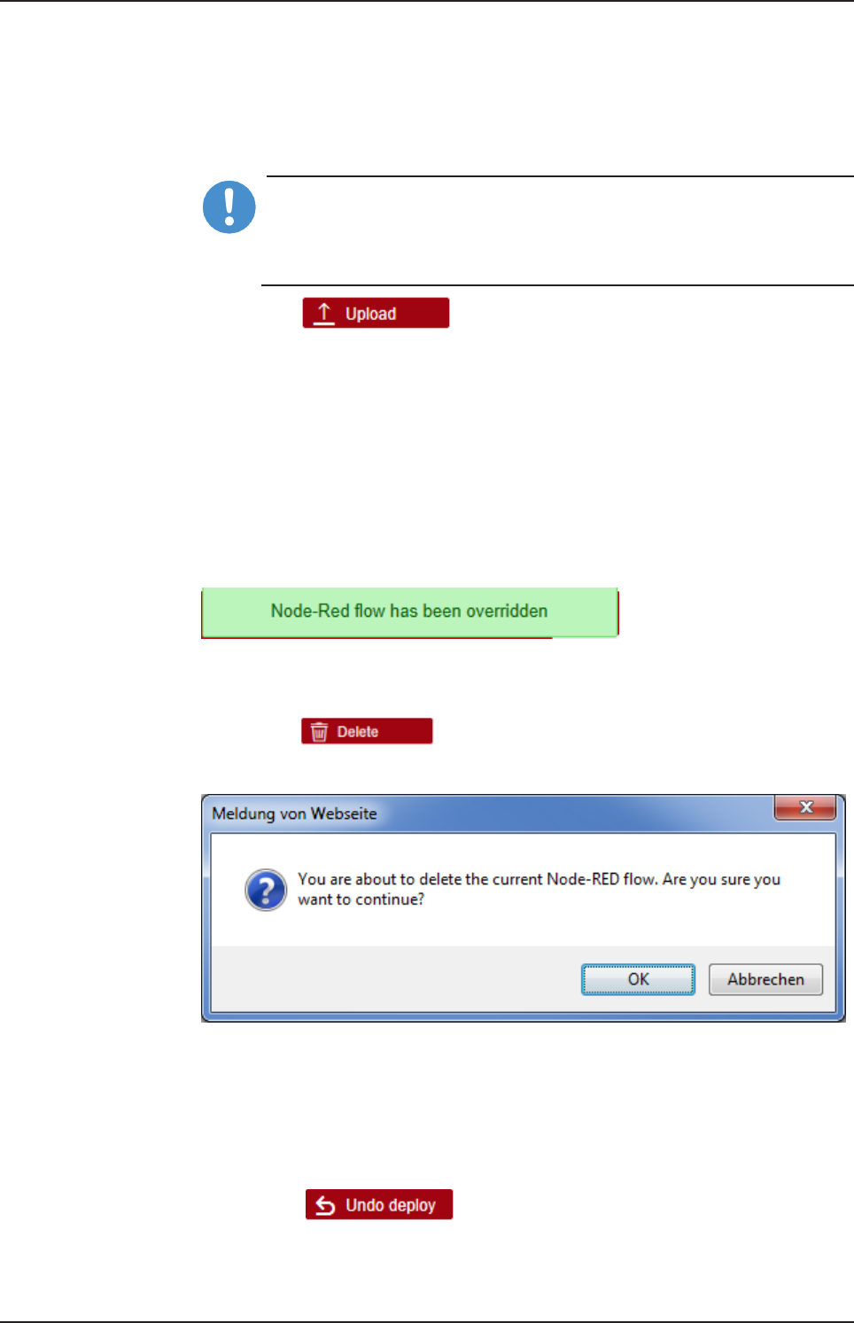
ðThe selected flow is uploaded now. This overwrites the previously
loaded flow. The message Node-RED flow has been overridden is
displayed.
Figure27: Message at overwriting of current NodeRED flow
Deleting the current Node-RED flow
ØClick at .
ÊThe following security request is displayed:
Figure28: Security request at deletion of current NodeRED flow.
ØClick at OK.
ðThe current Node-RED flow is deleted. Afterwards, there is no chance
to restore this flow anyway.
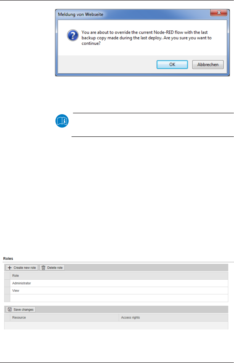
Undo last deploy in Node-RED
ØClick on .
ÊA security query warns for danger of data loss due to undo of deploy.
netPI | NOIT-E-NPI3-51-EN-RE
DOC170801UM01EN | Revision 1 - Draft 1 | English | 2017-09 | Draft | Public
© Hilscher 2017
Control Panel 40/57
Figure29: Security query for Undo last deploy
ØIf you are really sure that you want to undo the last deploy, then click on
OK.
ðThe last deploy is undone.
Note:
For further information about Deploy in Node-RED, see section
Menu Deploy.
8.2.6 User management
The administrator manages users by means of two configuration pages:
·User roles (determining new roles and assigning access rights) and
·User accounts (adding, processing, and deleting).
Defining a user account is accomplished by assigning a predefined role to
the user.
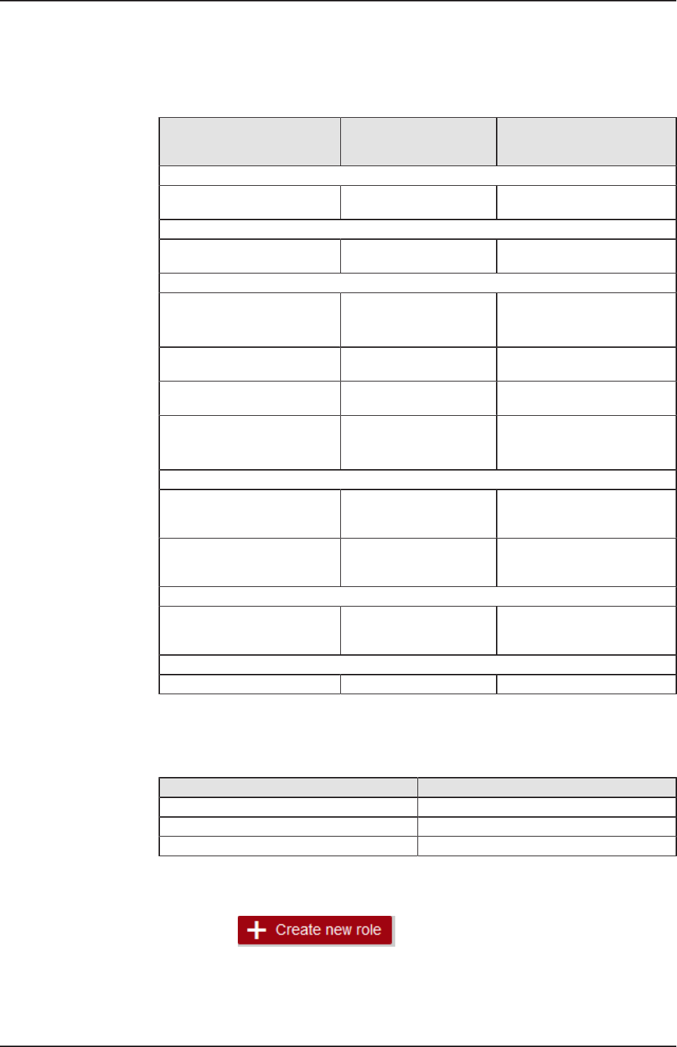
8.2.6.1 Managing user roles
Open this page with User Management > Roles.
On this page, you can determine roles and assign access rights onto
resources to these roles.
The roles Administrator and View are standard and cannot be deleted.
Figure30: Page for configuring roles
netPI | NOIT-E-NPI3-51-EN-RE
DOC170801UM01EN | Revision 1 - Draft 1 | English | 2017-09 | Draft | Public
© Hilscher 2017
Control Panel 41/57
An access right is set per resource. Each configuration page of the control
panel which contains settable device parameters is a resource. Access via
REST-API (see Functions of the Edge Server) is also a resource.
An access right can be assigned to the following single resources:
Access right / Resource Access to resource
accomplished via menu
entry
Usage
System
Setting the system time System >Time Setting the system
time [}page30]
Packet management
Managing packets Package Manager >
Packages
Managing packets [}page33]
Network access
Access to LAN (Ethernet
network)
Network > LAN Configuring Ethernet
communication
(LAN) [}page35]
Access onto WiFI (wireless
network)
Network > WiFi Configuring wireless
communication (WiFi)
Access onto hostname of Edge
Gateway
Network > Hostname Hostname [}page36]
Access onto Field network
(Ethernet network)
Network > Field
Services
Configure Node-RED Services > Node-RED Starting, stopping and
configuring
services [}page37]
Configure MQTT Broker Services > MQTT Broker Starting, stopping and
configuring
services [}page37]
Security
Install security certificates Security > SSL/TLS
Certicate
Uploading and installing own
security
certificates [}page43]
Edge Server
Access via REST-API Edge Server (REST API) Functions of the Edge Server
Table17: Access rights onto resources
Each resource may obtain one of the following access rights:
Access rights onto resource Checkbox
No access None
Read access only Read
Read and write access Read, Write
Table18: Access rights to resources
Adding a new role
ØClick at
netPI | NOIT-E-NPI3-51-EN-RE
DOC170801UM01EN | Revision 1 - Draft 1 | English | 2017-09 | Draft | Public
© Hilscher 2017
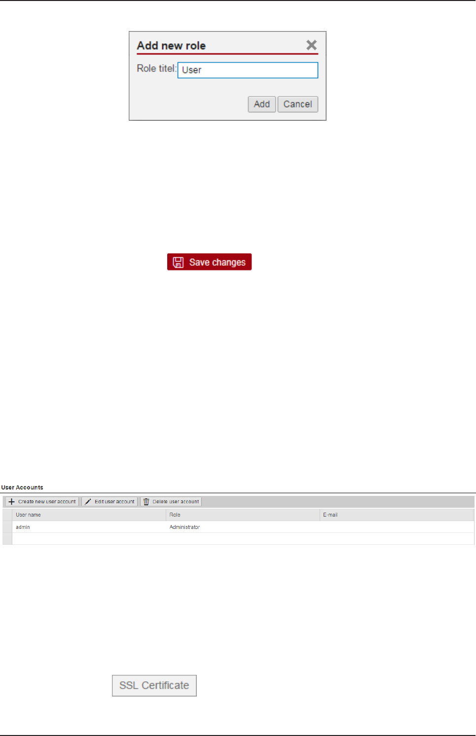
Control Panel 42/57
ðThe dialog box for entering the role name is displayed.
ØEnter a name for the role, e.g. User.
ØClick Add.
ðThe role is added.
Setting the access rights of a role
ØClick a role.
ðThe resources and access rights for this role will be displayed.
ØAssign the access right per resource.
ØClick at
The following figure shows the access rights of the administrator.
Also see about this
2Uploading and installing own security certificates [}43]
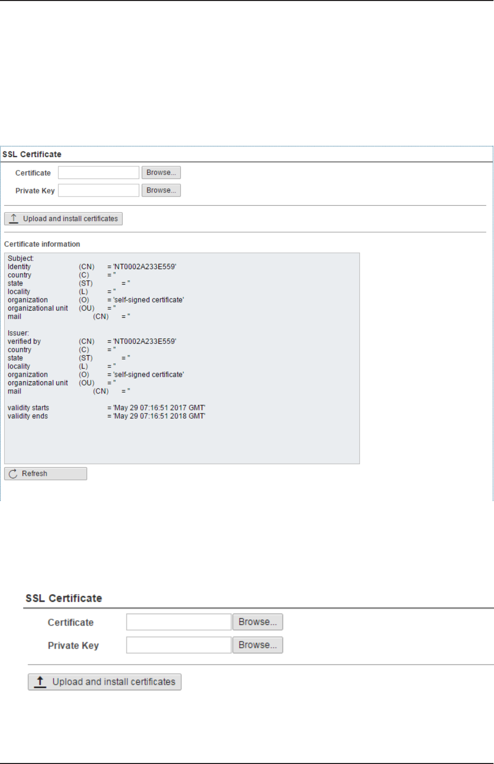
8.2.6.2 Managing user accounts
Open this page with User Management > Accounts.
On this page you can
·add
·process
·delete user accounts.
Figure31: User account page
Each user account has a user name, a password, and an assigned role.
8.2.7 Security certificates
The menu Security offers you the possibility to display the contents of
security certificates and to upload and install these.
It looks like:
Figure32: Security submenu
netPI | NOIT-E-NPI3-51-EN-RE
DOC170801UM01EN | Revision 1 - Draft 1 | English | 2017-09 | Draft | Public
© Hilscher 2017
Control Panel 43/57
On selection of menu entry SSL certificate the page SSL certificate is
opened.
In order to access this page you require the following access right:
Install security certificates
This page SSL certificate displays information about the currently used
security certificate. You also can upload and install a new security
certificate here (File extension *.pem, file size <=0.5 MB).
Figure33: Page SSL Certificate
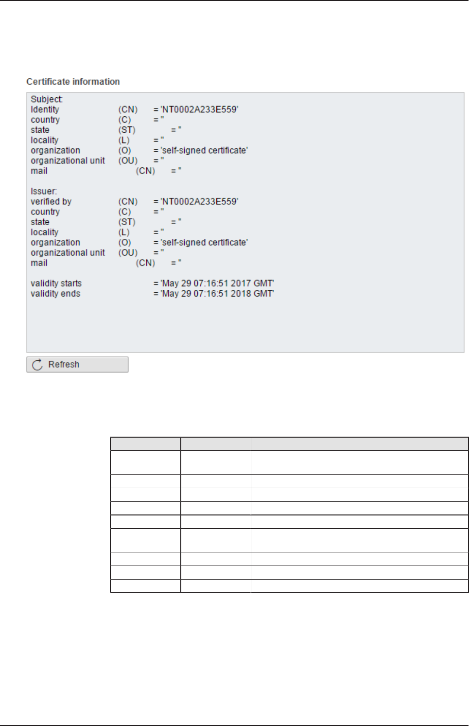
8.2.7.1 Uploading and installing own security certificates
In the upper area of page SSL Certificate you can select an own security
certificate including the private key that is associated with the certificate.
Figure34: SSL Certificate – Upload area
netPI | NOIT-E-NPI3-51-EN-RE
DOC170801UM01EN | Revision 1 - Draft 1 | English | 2017-09 | Draft | Public
© Hilscher 2017

Control Panel 44/57
Uploading and installing the certificate
1. In order to upload and install the certificate, proceed as follows:
ØSelect your certificate to be uploaded and installed with the Browse
button right of the field Certificate.
ØSelect the private key associated with your certificate with the Browse
button right of the field Private Key.
Note:
The expected file type for security certificates and private keys is
*.pem (Privacy enhanced electronic mail format). You can find
more information about this file format in Wikipedia at https://
en.wikipedia.org/wiki/Privacy-enhanced_Electronic_Mail.
ØClick at Upload and install certificates.
ðThe security certificate is uploaded and installed.
netPI | NOIT-E-NPI3-51-EN-RE
DOC170801UM01EN | Revision 1 - Draft 1 | English | 2017-09 | Draft | Public
© Hilscher 2017
Control Panel 45/57
8.2.7.2 Information about the currently loaded security certificate
In the lower area of page SSL Certificate information concerning the
currently loaded security certificate is displayed.
Figure35: SSL Certificate – Info area
The single lines have the following meanings:
Information about the security certificate
Line Abbreviation Meaning
Identity
/verified by
CN Identity/verified by
country C Country
state ST State
locality L Locality
organization O Organization
Organization
unit
OU Organization unit
mail CN E-mail address
Validity starts - Start of validity duration of certificate
Validity ends - End of validity duration of certificate
In factory-new state the Edge Gateway contains a self-signed certificate.
You should replace this by an own certificate that you can upload and
install in the way described above (see Uploading and installing own
security certificates [}page43]).
netPI | NOIT-E-NPI3-51-EN-RE
DOC170801UM01EN | Revision 1 - Draft 1 | English | 2017-09 | Draft | Public
© Hilscher 2017
Control Panel 46/57
8.2.8 Help
Open this page with Help> Info. No access rights are required in order to
open this page.
This page displays the firmware version of the Edge Gateway.
Figure36: Info page
8.2.9 Session
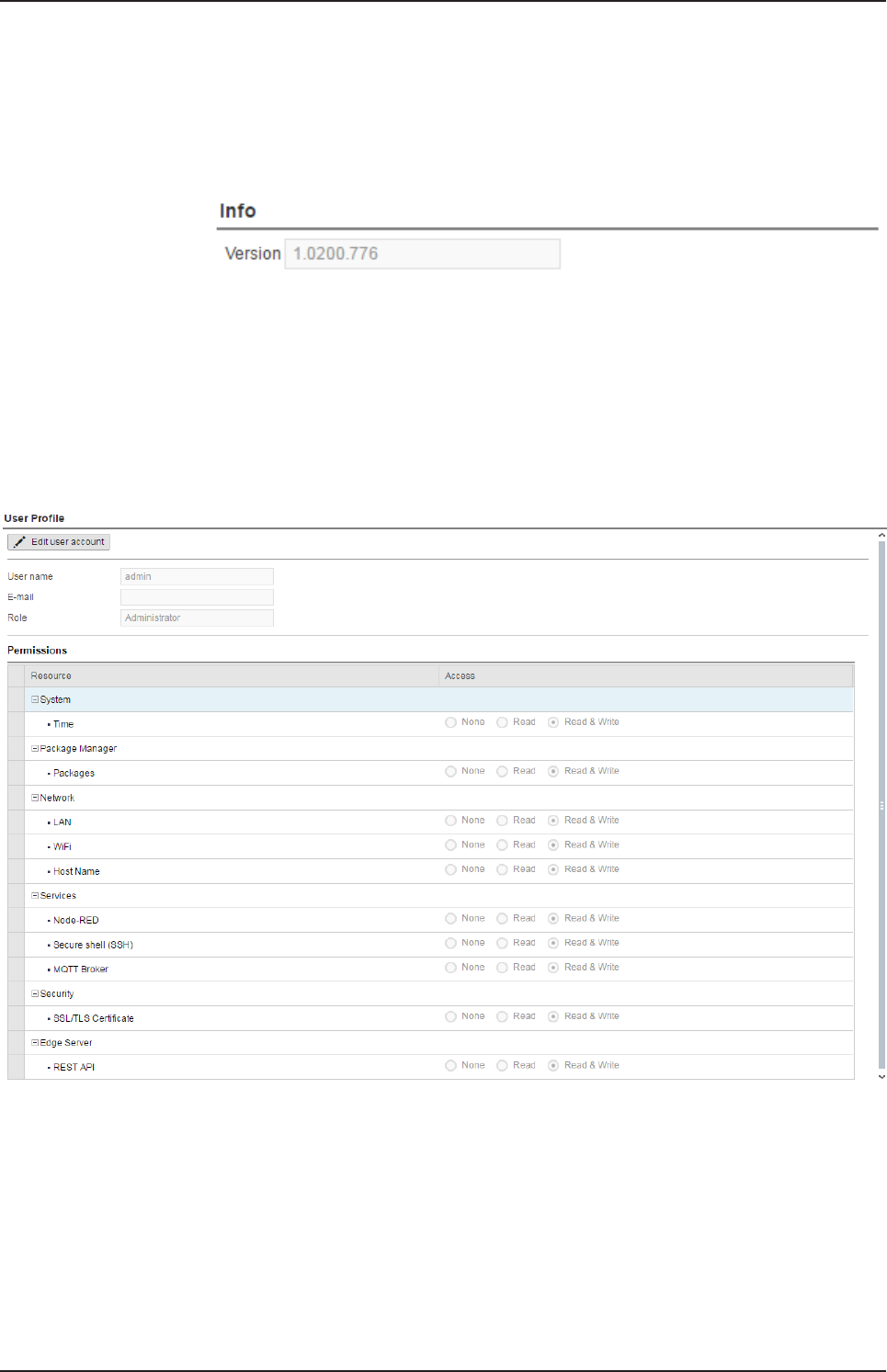
8.2.9.1 User profile
Open this page with Session> User Profile. No access rights are required
in order to open this page.
Figure37: User profile page
On this page you can
·display the access rights of your user account,
·change your E-mail address, and
·change your password.
netPI | NOIT-E-NPI3-51-EN-RE
DOC170801UM01EN | Revision 1 - Draft 1 | English | 2017-09 | Draft | Public
© Hilscher 2017
Control Panel 47/57
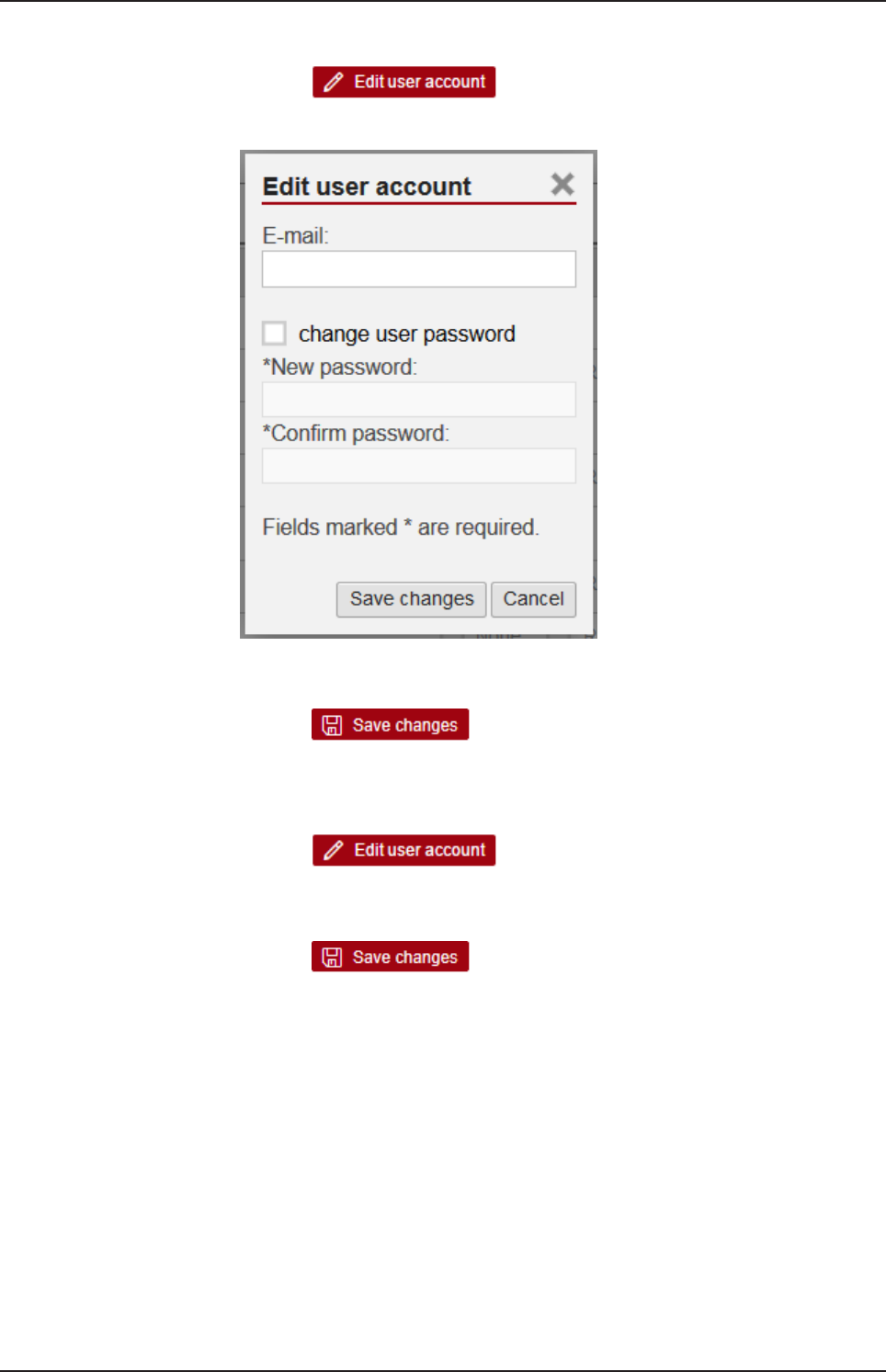
Changing the e-mail address
ØClick at .
ÊThe dialog Edit user account is displayed.
Figure38: Dialog "Edit user account"
ØSpecify your e-mail address at the input field E-mail.
ØClick at .
ðThe specified e-mail address is stored.
Changing the password
ØClick at .
ÊThe dialog Edit user account is displayed (see figure above).
ØCheck change user password.
ØClick at .
ØSpecify your password at the input field New Password.
ØIn order to confirm your input, specify your password again at the input
field Confirm Password.
ðThe changed password is stored.
8.2.9.2 Logout
To log out from the Edge Gateway, use Session> Logout. No access
rights are required to select this menu entry. Prior to accessing the Edge
Gateway again, a new login (Specifying user name and password) is
necessary.
netPI | NOIT-E-NPI3-51-EN-RE
DOC170801UM01EN | Revision 1 - Draft 1 | English | 2017-09 | Draft | Public
© Hilscher 2017

Isolated application execution with Docker 48/57
9 Isolated application execution with Docker
The Edge Gateway enables the user to execute his own applications within
the protected Linux operating system. A software platform becomes
necessary to allow the execution of said applications without
simultaneously opening the possibility of evading the safety mechanisms of
the Linux operating system. For that purpose, the Edge Gateway uses the
open-source software "Docker" from Docker Inc. (https://
www.docker.com/).
In order to work with Docker, read and write access rights at Docker UI are
required. You can check whether you have the required access rights via
the menu entry User profile [}page46]. Granting read and right access
rights requires administrator rights and is described in section Managing
user roles [}page40].
Note:
For more information on Docker, see the documentation of the
Docker organization under https://docs.docker.com/.
9.1 Working with Docker via the web GUI
This section describes
·how to operate Docker via the portainer.io interface of the browser
·how to run additional software on the Edge Gateway with Docker (using
the web server NGINX as an example).
9.1.1 The portainer.io interface
Tasks of the portainer.io interface
The portainer.io interface serves:
·to add new containers
·to provide functions for controlling the code execution such as Start,
Stop, Kill, Restart, Pause, Resume, and Remove
·to configure the containers.
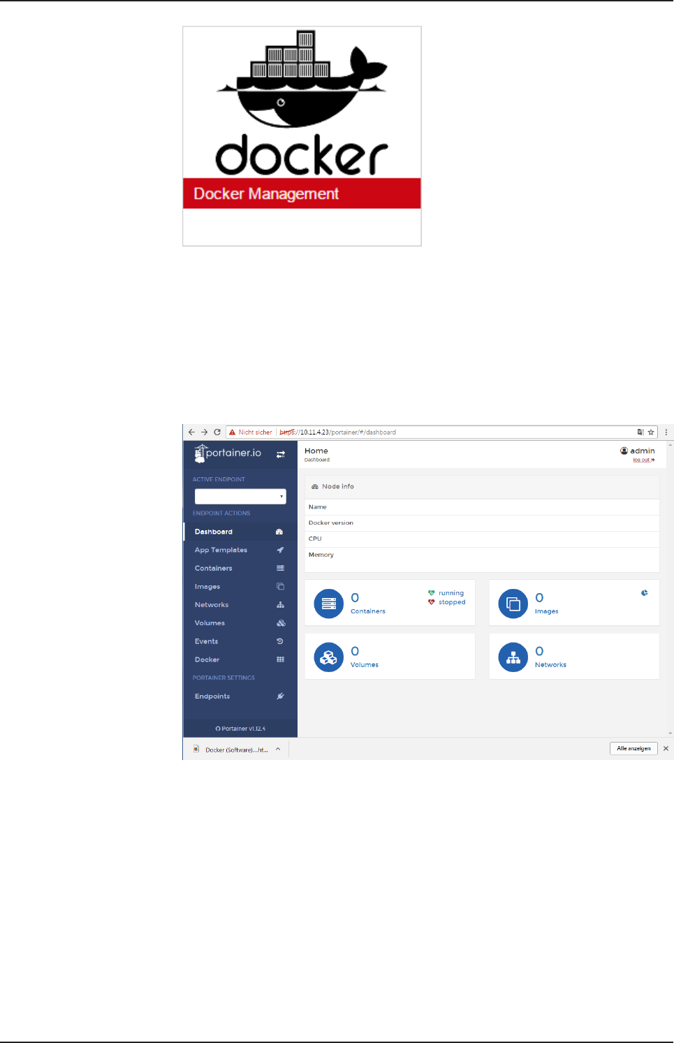
Starting the portainer.io interface for working with the containers
To start the portainer.io interface, proceed as follows:
ØOpen the Edge Gateway Manager, if it is not already open.
For this purpose see Calling the Edge Gateway Manager [}page20]
ØClick the tile Docker Management in the Edge Gateway Manager..
netPI | NOIT-E-NPI3-51-EN-RE
DOC170801UM01EN | Revision 1 - Draft 1 | English | 2017-09 | Draft | Public
© Hilscher 2017
Isolated application execution with Docker 49/57
Figure39: Tile Docker in the Edge Gateway Manager
ÊThe portainer.io login screen will be displayed. In the field Username,
admin is already entered. This is the only predefined user name.
ØEnter the password for the user name admin. This password is set in
the user management of the Edge Gateway Manager, see User
management [}page40].
ÊThe start page "Dashboard" of the user interface portainer.io will be
displayed.
Figure40: View of portainer.io dashboard
ØClick Containers in the menu on the left or Containers on the page
"Dashboard".
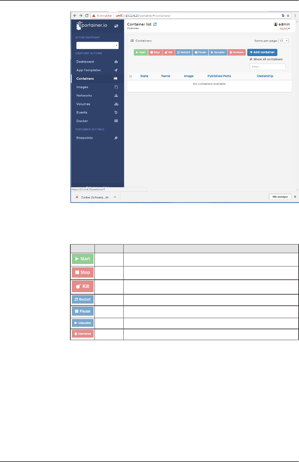
ðThe page "Container list" will be displayed. This list contains the names
and statuses of all currently known containers and provides the
functions for controlling the code execution.
netPI | NOIT-E-NPI3-51-EN-RE
DOC170801UM01EN | Revision 1 - Draft 1 | English | 2017-09 | Draft | Public
© Hilscher 2017
Isolated application execution with Docker 50/57
Figure41: Container list (portainer.io)
Functions for working with containers
Docker provides the following functions for controlling the code execution:
Icon Function Meaning
Start Starting a container
Stop Stopping a container
Kill Aborting the execution of a container
Restart Repeated starting of a container
Pause Interrupting the execution of a container temporarily
Resume Continuing the execution of a container after an interruption
Remove Deleting a container
Table19: Functions for working with containers
netPI | NOIT-E-NPI3-51-EN-RE
DOC170801UM01EN | Revision 1 - Draft 1 | English | 2017-09 | Draft | Public
© Hilscher 2017
Decommissioning, dismounting and disposal 51/57
10 Decommissioning, dismounting and disposal
10.1 Putting the device out of operation
Danger of Unsafe System Operation!
To prevent personal injury or property damage, make sure that the removal
of the device from your plant during operation will not affect the safe
operation of the plant.
ØDisconnect all communication cables from the device.
ØDisconnect the power supply plug.
ØRemove the device from the DIN top hat rail. .
10.2 Removing device from top hat rail
ØBefore dismounting the Edge Gateway from the top hat rail, first remove
the power supply cable and all data cables from the device.
ØPut a screw driver into the slot of the latch at the bottom of the device.
ØTo disengage the lock of the hook, pull down the latch with the screw
driver.
ØTake the device off the top hat rail.
10.3 Disposal of waste electronic equipment
Important notes from the European Directive 2002/96/EU “Waste Electrical
and Electronic Equipment (WEEE)”
Waste electronic equipment
This product must not be treated as household waste.
This product must be disposed of at a designated waste electronic
equipment collecting point.
Waste electronic equipment may not be disposed of as household waste.
As a consumer, you are legally obliged to dispose of all waste electronic
equipment according to national and local regulations.
netPI | NOIT-E-NPI3-51-EN-RE
DOC170801UM01EN | Revision 1 - Draft 1 | English | 2017-09 | Draft | Public
© Hilscher 2017

Technical data 52/57
11 Technical data
11.1 Technical data NIOT-E-NPI3-51-EN-RE
Parameter Value
Part number 1321.500
Application For IoT purpose.
Operating system PROFINET IO
EtherNet/IP
Operating system Security Enhanced Linux
CPU 1.2 GHz Broadcom BCM2837
LAN interface 1 x 10/100 Mbit, Microchip LAN9514
Fieldbus (Real-Time
Ethernet) interface
2 x 10/100 Mbit, Hilscher netX51
Memory 1 GB DDR3 RAM, 4 GB SD memory
Real-time clock Yes, maintenance free
Wi-Fi 802.11bgn
Display connection HDMI
USB 4 x USB 2.0 (500 mA)
Serial interface -
Power supply 19.2 V DC … 28 V DC
Current (at 24 V DC) Tbd
Operating temperature 0 °C ... + 60 °C
Dimensionen (H x W x L) 120 x 40 x 100 mm
Table20: Technical datd NIOT-E-TPI51-EN-RE
netPI | NOIT-E-NPI3-51-EN-RE
DOC170801UM01EN | Revision 1 - Draft 1 | English | 2017-09 | Draft | Public
© Hilscher 2017
Bluetooth V4.1
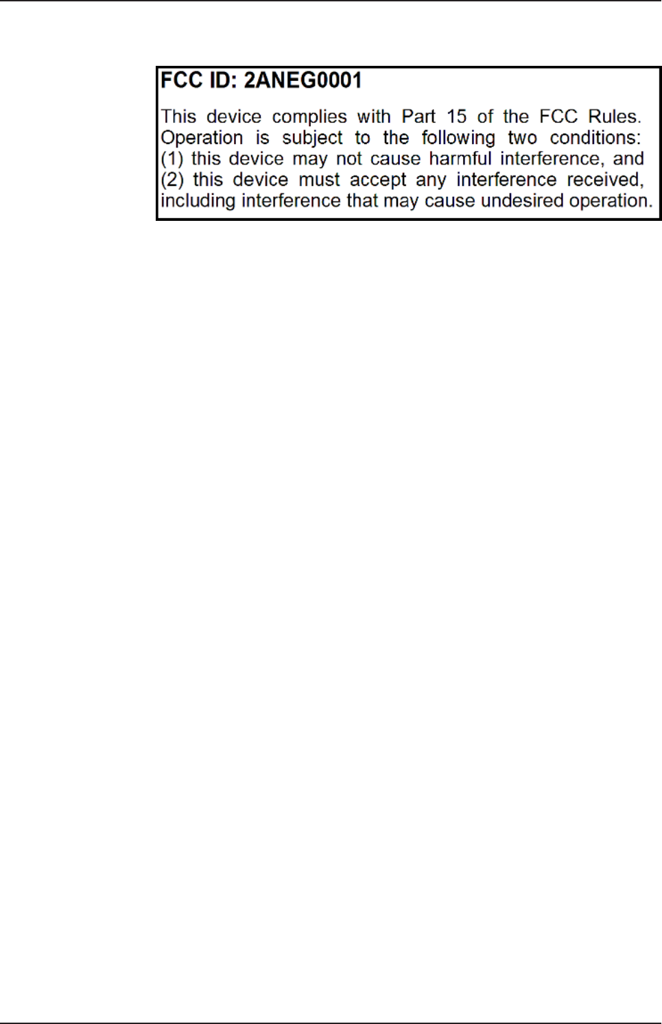
FCC authorization 53/57
12 FCC authorization
Figure42: FCC label
Changes or modifications not expressly approved by the party responsible
for compliance could void the user’s authority to operate the equipment.
This equipment has been tested and found to comply with the limits for a
Class B digital device, pursuant to Part 15 of the FCC Rules. These limits
are designed to provide reasonable protection against harmful interference
in a residential installation. This equipment generates, uses and can radiate
radio frequency energy and, if not installed and used in accordance with the
instructions, may cause harmful interference to radio communications.
However, there is no guarantee that interference will not occur in a
particular installation.
If this equipment does cause harmful interference to radio or television
reception, which can be determined by turning the equipment off and on,
the user is encouraged to try to correct the interference by one or more of
the following measures:
·Reorient or relocate the receiving antenna.
·Increase the separation between the equipment and receiver.
·Connect the equipment into an outlet on a circuit different from that to
which the receiver is connected.
·Consult the dealer or an experienced radio/TV technician for help.
This equipment complies with FCC radiation exposure limits set forth for an
uncontrolled environment. This equipment should be installed and operated
with minimum distance 20cm between the radiator and your body. This
transmitter must not be co-located or operating in conjunction with any
other antenna or transmitter.
netPI | NOIT-E-NPI3-51-EN-RE
DOC170801UM01EN | Revision 1 - Draft 1 | English | 2017-09 | Draft | Public
© Hilscher 2017

List of figures 54/57
List of figures
Figure 1: NIOT-E-NPI3-51-EN-RE (Top view)..................................................................... 10
Figure 2: NIOT-E-NPI3-51-EN-RE (Front view)................................................................... 10
Figure 3: NIOT-E-NPI3-51-EN-RE (Bottom view)................................................................ 11
Figure 4: Dimensions........................................................................................................... 11
Figure 5: NIOT-E-NPI3-51-EN-RE LED positions ............................................................... 14
Figure 6: Gateway state LEDs............................................................................................. 15
Figure 7: netIOT Edge Gateway in the Windows network ................................................... 19
Figure 8: Properties of the Edge Gateway........................................................................... 19
Figure 9: Edge Gateway Manager....................................................................................... 20
Figure 10: Edge Gateway Manager - Setting the administrator password ............................ 23
Figure 11: Security error message of the Internet Explorer................................................... 25
Figure 12: Security error message of the Firefox browser (1) ............................................... 25
Figure 13: Security error message of the Firefox browser (2) ............................................... 25
Figure 14: Firefox dialog box: Adding exceptional safety rule ............................................... 26
Figure 15: Security error message of Google Chrome (1)..................................................... 26
Figure 16: Security error message of Google Chrome (2)..................................................... 27
Figure 17: Main menu of the Control Panel ........................................................................... 28
Figure 18: Page Info Center .................................................................................................. 29
Figure 19: Time configuration page ....................................................................................... 30
Figure 20: Reboot safety query ............................................................................................. 32
Figure 21: Warning for consequences of shutdown .............................................................. 32
Figure 22: Packages installed................................................................................................ 33
Figure 23: Table of the packages that are available for installation....................................... 34
Figure 24: Message box "Upload - Failed to install packages..."........................................... 35
Figure 25: Hostname ............................................................................................................. 36
Figure 26: List of default services .......................................................................................... 37
Figure 27: Message at overwriting of current NodeRED flow................................................ 39
Figure 28: Security request at deletion of current NodeRED flow. ........................................ 39
Figure 29: Security query for Undo last deploy...................................................................... 40
Figure 30: Page for configuring roles..................................................................................... 40
Figure 31: User account page ............................................................................................... 42
Figure 32: Security submenu................................................................................................. 42
Figure 33: Page SSL Certificate ............................................................................................ 43
Figure 34: SSL Certificate – Upload area .............................................................................. 43
Figure 35: SSL Certificate – Info area ................................................................................... 45
Figure 36: Info page............................................................................................................... 46
Figure 37: User profile page .................................................................................................. 46
Figure 38: Dialog "Edit user account" .................................................................................... 47
Figure 39: Tile Docker in the Edge Gateway Manager.......................................................... 49
Figure 40: View of portainer.io dashboard............................................................................. 49
netPI | NOIT-E-NPI3-51-EN-RE
DOC170801UM01EN | Revision 1 - Draft 1 | English | 2017-09 | Draft | Public
© Hilscher 2017

List of figures 55/57
Figure 41: Container list (portainer.io) ................................................................................... 50
Figure 42: FCC label.............................................................................................................. 53
netPI | NOIT-E-NPI3-51-EN-RE
DOC170801UM01EN | Revision 1 - Draft 1 | English | 2017-09 | Draft | Public
© Hilscher 2017

List of tables 56/57
List of tables
Table 1: List of revisions ....................................................................................................... 4
Table 2: Power supply connector NIOT-E-TPI51-EN-RE ..................................................... 12
Table 3: Description of gateway status LEDs ....................................................................... 15
Table 4: LEDs LAN interface NIOT-E-TPI51-EN-RE............................................................ 16
Table 5: LED states for the PROFINET IO-Device protocol ................................................. 16
Table 6: LED state definitions for the PROFINET IO-Device protocol.................................. 16
Table 7: LED states for the EtherNet/IP Adapter protocol .................................................... 17
Table 8: LED state definitions for the EtherNet/IP Adapter protocol..................................... 17
Table 9: Starting applications with the Edge Gateway manager .......................................... 21
Table 10: Functional overview of the Control Panel ............................................................... 28
Table 11: Info Center: Area System info................................................................................. 29
Table 12: Info Center: Area Monitoring................................................................................... 29
Table 13: Info Center: Area Temperature............................................................................... 30
Table 14: Setting the system time .......................................................................................... 30
Table 15: Table LAN: Meaning of the columns....................................................................... 36
Table 16: Operating statuses of the services ......................................................................... 37
Table 17: Access rights onto resources.................................................................................. 41
Table 18: Access rights to resources...................................................................................... 41
Table 19: Functions for working with containers..................................................................... 50
Table 20: Technical datd NIOT-E-TPI51-EN-RE .................................................................... 52
netPI | NOIT-E-NPI3-51-EN-RE
DOC170801UM01EN | Revision 1 - Draft 1 | English | 2017-09 | Draft | Public
© Hilscher 2017

Contacts 57/57
Contacts
HEADQUARTERS
Germany
Hilscher Gesellschaft für
Systemautomation mbH
Rheinstrasse 15
D-65795 Hattersheim
Phone: +49 (0) 6190 9907-0
Fax: +49 (0) 6190 9907-50
E-Mail: info@hilscher.com
Support
Phone: +49 (0) 6190 9907-99
E-Mail: de.support@hilscher.com
SUBSIDIARIES
China
Hilscher Systemautomation (Shanghai) Co. Ltd.
200010 Shanghai
Phone: +86 (0) 21-6355-5161
E-Mail: info@hilscher.cn
Support
Phone: +86 (0) 21-6355-5161
E-Mail: cn.support@hilscher.com
France
Hilscher France S.a.r.l.
69500 Bron
Phone: +33 (0) 4 72 37 98 40
E-Mail: info@hilscher.fr
Support
Phone: +33 (0) 4 72 37 98 40
E-Mail: fr.support@hilscher.com
India
Hilscher India Pvt. Ltd.
Pune
Phone: +91 8888 750 777
E-Mail: info@hilscher.in
Italy
Hilscher Italia S.r.l.
20090 Vimodrone (MI)
Phone: +39 02 25007068
E-Mail: info@hilscher.it
Support
Phone: +39 02 25007068
E-Mail: it.support@hilscher.com
Japan
Hilscher Japan KK
Tokyo, 160-0022
Phone: +81 (0) 3-5362-0521
E-Mail: info@hilscher.jp
Support
Phone: +81 (0) 3-5362-0521
E-Mail: jp.support@hilscher.com
Korea
Hilscher Korea Inc.
Seongnam, Gyeonggi, 463-400
Phone: +82 (0) 31-789-3715
E-Mail: info@hilscher.kr
Switzerland
Hilscher Swiss GmbH
4500 Solothurn
Phone: +41 (0) 32 623 6633
E-Mail: info@hilscher.ch
Support
Phone: +49 (0) 6190 9907-99
E-Mail: ch.support@hilscher.com
USA
Hilscher North America, Inc.
Lisle, IL 60532
Phone: +1 630-505-5301
E-Mail: info@hilscher.us
Support
Phone: +1 630-505-5301
E-Mail: us.support@hilscher.com
netPI | NOIT-E-NPI3-51-EN-RE
DOC170801UM01EN | Revision 1 - Draft 1 | English | 2017-09 | Draft | Public
© Hilscher 2017