Hilti PD38XR01 LASER RANGEMETER User Manual
Hilti Corporation LASER RANGEMETER Users Manual
UserManual.wiki
>
Hilti
>
PD38XR01 User Manual
Users Manual
Navigation menu
Upload a User Manual
Namespaces
Wiki Guide
HTML
PDF
Info
Views
User Manual
Discussion / Help
Navigation

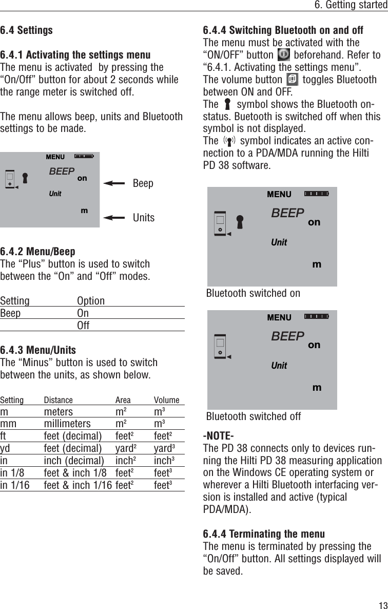
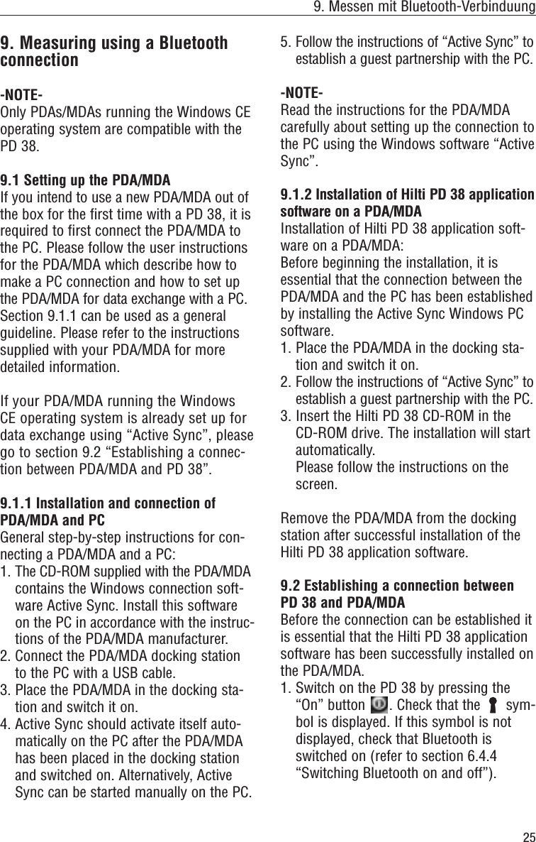
![4. Technical data4. Technical dataPower supply3V DC Type: AA (LR6, AM3, Mignon)Standard: two alkaline batteriesOptional: rechargeable NiMh batteriesBattery status indicatorBattery display with four segmentsshowing 100%, 75%, 50% and 25%chargedAll segments deleted = dischargedbatteryMeasuring range0.05 m to 200 m (2 in to 600 ft)0.05 m (2 in) from the front edgeMax. distance resolution 750 m(2,500 ft)Typical measuring range without tar-get plate:– Drywall panel, white 70 m (210 ft)– Concrete, dry 50 m (150 ft)– Brick, dry 50 m (150 ft)The maximum range depends on:– Reflectivity of the target surface– Ambient light conditionsIn case measurements are not possi-ble, use the Hilti PDA 50 target plate. Accuracy ±1.5 mm (±1/16 in) is typical forindividual and continuous measure-ments **** The measuring accuracy is affectedby ± (1.5 mm + 20 ppm)/± (1/16 in+20 ppm) due to atmospheric condi-tions. This effect is typically noticeableat distances > 100 m (> 300 ft).Smallest unit displayed1 mm (1/16 in)Beam diameter< 6 mm @ 10 m (< 0.2 in @ 30 ft)< 30 mm @ 50 m (< 1.2 in @ 150 ft)< 60 mm @ 100 m (< 2.4 in @ 300 ft)Basic operating modesSingle measurementContinuous measurementCalculation/functionsDisplayIlluminated liquid-crystal display showing operating status and batterystatusLaserVisible, 620–690 nm, laser class 2(IEC60825-1: 2003,CFR 21 § 1040 [FDA]) output power: < 1 mWAutomatic time-outLaser: 1 min.Range meter: 10 min.Battery life at 25 °C (77 °F)Max. number of measurements with single set of batteries (laser switched on for 10 sec.)Alkaline: 8,000–10,000NiMH: 6,000– 8,000Operating temperature–10 °C…+ 50 °C (14 °F… 122 °F)Storage temperature–30 °C…+ 70 °C (–22 °F… 158 °F)Protection classDust and splash-proof, IP 54 as per IEC529 standardWeight220 g/0.48 lb (without batteries)Dimensions120 (L) x 65 (W) x 28 (H) mm4.7" (L) x 2.5" (W) x 1.1" (H) in8](https://usermanual.wiki/Hilti/PD38XR01/User-Guide-622782-Page-12.png)