Users Manual

*228790*
228790
Hilti Corporation
FL-9494 Schaan
Tel.: +423 / 234 21 11
Fax: +423 / 234 29 65
www.hilti.com
Hilti = registered trademark of Hilti Corp., Schaan W 3153 1105 00-Pos. 4 1 Printed in Liechtenstein © 2005
Right of technical and programme changes reserved S. E. & O. 228790 / A
PD 38
Bedienungsanleitung de
Operating instructions en
Ẅ
52
49
6
31
7
12
810
10
11
11
11
13
PDAW 80-1
ẅ
PDA 50
PDA 60
PDA 61
PDA 62
PDA 70
PDAW 80 / 81-3
PDAW 81-1
PDAW 80 / 81-2
PDAW 80 / 81-1
PDA 81
PDA 80
PUA 60
PDA 66

PD 38 laser range meter Contents
It is essential that the operating
instructions are read before the range
meter is used the first time.
Always keep these operating instruc-
tions together with the range meter.
Ensure that the operating instructions
are with the range meter when it is
given to other persons.
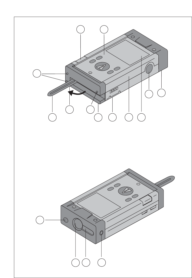
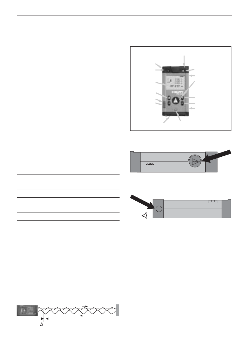
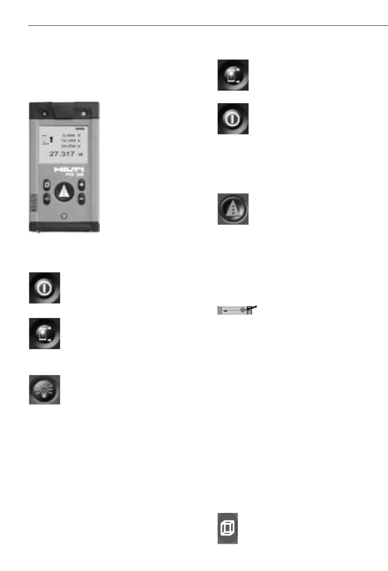
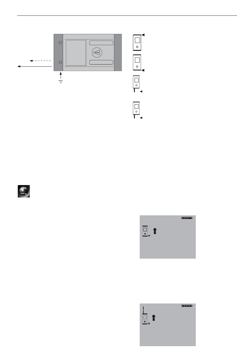
Component parts Ẅ
ቢLaser exit aperture
ባControl panel
ቤReceiving lens
ብPlastic casing
ቦHorizontal bubble
ቧVertical bubble
ቨBattery compartment
ቩFolding spike
ቪGraphic display showing operating
status
ቫMetal contact points for precise meas-
urement (3x rear)
ቭMetal supports for precise measure-
ment (3x underneath)
ቮOptical sight
ቯSide measure button
Contents
1. General information. . . . . . . . . . 3
1.1 Safety notices and their
meaning . . . . . . . . . . . . . . . . . . . 3
1.2 Pictograms . . . . . . . . . . . . . . . . . 3
1.3 Location of identification data on
the range meter . . . . . . . . . . . . . 3
2. Description. . . . . . . . . . . . . . . . . 4
2.1 Intended use. . . . . . . . . . . . . . . . 4
2.2 Items supplied . . . . . . . . . . . . . . 4
2.3 Measuring principle . . . . . . . . . . 4
2.4 Range meter functions . . . . . . . . 4
2.4.1 General range meter functions . . 4
2.4.2 PD 38 side measure button . . . . 4
2.4.3 PD 38 optical sight . . . . . . . . . . . 4
2.5 Bluetooth . . . . . . . . . . . . . . . . . . 4
3. Tools and accessories . . . . . . . . 6
3.1 PDA 50 target plate. . . . . . . . . . . 6
3.2 PDA 80/81charging kits . . . . . . . 6
3.3 PDAW 80-1 mains adapter . . . . . 6
3.4 PDAW 80/81-2 car battery
plug. . . . . . . . . . . . . . . . . . . . . . . 7
3.5 PDAW 80/81-1 charging adapter . 7
3.6 PDAW 80/81-3 battery pack . . . . 7
3.7 PDAW 81-1 mains adapter . . . . . 7
3.8 PUA 60 laser visibility glasses . . 7
3.9 PDA 62 belt clip . . . . . . . . . . . . . 7
3.10 PDA 70 measuring extension . . 7
3.11 PDA 66 Holder . . . . . . . . . . . . . . 7
4. Technical data . . . . . . . . . . . . . . 8
5. Safety information . . . . . . . . . . . 9
5.1 Basic safety information . . . . . . . 9
5.2 Misuse . . . . . . . . . . . . . . . . . . . . 9
5.3 General safety precautions . . . . . 9
5.4 Proper organization of
workplace . . . . . . . . . . . . . . . . . 10
5.4.1 Electromagnetic compatibility. . 10
5.4.2 Laser classification . . . . . . . . . . 10
5.4.3 Transport . . . . . . . . . . . . . . . . . 10
1

2
Contents
6. Getting started . . . . . . . . . . . . . 11
6.1 Inserting alkaline/rechargeable
batteries . . . . . . . . . . . . . . . . . . 11
6.2 Battery charging . . . . . . . . . . . . 11
6.2.1 Standard charging of batteries . 11
6.2.2 Fast battery charging . . . . . . . . 12
6.3 Switching the range meter
on and off . . . . . . . . . . . . . . . . . 12
6.3.1 Initial distance measurement . . 12
6.4 Settings. . . . . . . . . . . . . . . . . . . 13
6.4.1 Activating the settings menu . . 13
6.4.2 Menu/Beep . . . . . . . . . . . . . . . . 13
6.4.3 Menu/Units . . . . . . . . . . . . . . . . 13
6.4.4 Switching Bluetooth on and off. 13
6.4.5 Terminating the menu. . . . . . . . 13
7. PD 38 operation. . . . . . . . . . . . 14
7.1 General controls . . . . . . . . . . . . 14
7.1.1 Control panel . . . . . . . . . . . . . . 14
7.1.2 On/off and control buttons . . . . 14
7.1.3 Measure buttons. . . . . . . . . . . . 14
7.1.4 Function buttons. . . . . . . . . . . . 14
7.2 Display . . . . . . . . . . . . . . . . . . . 15
7.2.1 Symbols displayed . . . . . . . . . . 15
7.2.2 Display illumination . . . . . . . . . 16
7.3 Optical sight . . . . . . . . . . . . . . . 16
7.4 Measuring distances. . . . . . . . . 17
7.4.1 Measuring references . . . . . . . . 17
7.4.2 Measuring distances step by
step . . . . . . . . . . . . . . . . . . . . . . 17
7.4.3 Measurement mode . . . . . . . . . 18
7.4.4 Measuring from corners . . . . . . 19
7.4.5 Measuring with the aid of target
objects . . . . . . . . . . . . . . . . . . . 19
7.4.6 Measuring in bright conditions . . 19
7.4.7 Taking measurements to rough
surfaces . . . . . . . . . . . . . . . . . . 20
7.4.8 Taking measurements to round
or inclined surfaces . . . . . . . . . 20
7.4.9 Taking measurements to wet or
shiny surfaces. . . . . . . . . . . . . . 20
7.4.10 Taking measurements to
transparent surfaces. . . . . . . . . 20
7.4.11 Measuring ranges. . . . . . . . . . . 20
8. Applications and functions . . . 21
8.1 Measurement data memory . . . 21
8.1.1 Saving measurements . . . . . . . 21
8.1.2 Historical data memory. . . . . . . 21
8.2 Area measurement . . . . . . . . . . 21
8.3 Volume measurement. . . . . . . . 22
8.4 Adding distances . . . . . . . . . . . 23
8.5 Subtracting distances . . . . . . . . 23
8.6 Setting out . . . . . . . . . . . . . . . . 24
9. Measuring using a Bluetooth
connection . . . . . . . . . . . . . . . . 25
9.1 Setting up PDA/MDA . . . . . . . . 25
9.2
Establishing connection between
PD 38 and PDA/MDA . . . . . . . . 25
9.3 Measuring using Bluetooth
connection to PDA/MDA . . . . . . 26
10. PDA/MDA Windows CE with
Hilti PD 38 application . . . . . . 27
11. Data transfer from PDA/MDA
to PC. . . . . . . . . . . . . . . . . . . . . 28
12. Calibration and adjustment. . . 29
12.1 Calibration. . . . . . . . . . . . . . . . . 29
12.2 Adjustment . . . . . . . . . . . . . . . . 30
12.3 Hilti calibration service . . . . . . . 30
13. Care and maintenance. . . . . . . 30
13.1 Cleaning and drying . . . . . . . . . 30
13.2 Storage . . . . . . . . . . . . . . . . . . . 30
13.3 Transportation. . . . . . . . . . . . . . 30
14. Disposal . . . . . . . . . . . . . . . . . . 31
15. Warranty. . . . . . . . . . . . . . . . . . 31
16. FCC statement (applicable in
USA) . . . . . . . . . . . . . . . . . . . . . 32
17. Troubleshooting . . . . . . . . . . . . 33
18. Bluetooth declaration of
compliance. . . . . . . . . . . . . . . . 33
19. EC declaration of conformity. . 34
3
1. General information
1. General information
1.1 Safety notices and their meaning
-CAUTION-
This word indicates a possibly hazardous
situation which could result in slight bodily
injuries or damage to property.
-NOTE-
This word indicates information to help the
user employ the product efficiently, and
other useful notes.
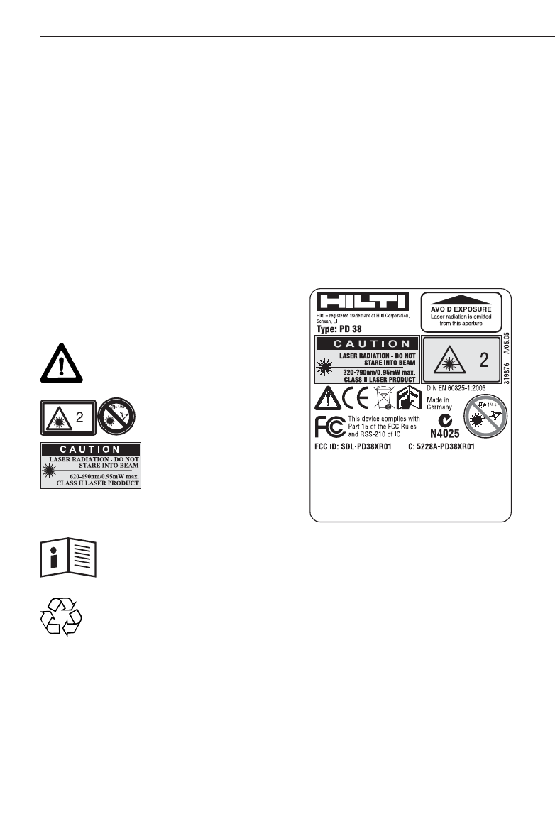
1.2 Pictograms
Warning signs
Symbols
Ẅ These numbers refer to the correspon-
ding illustrations. The illustrations can be
found on the fold-out cover pages. Keep
these pages open when studying the oper-
ating instructions. In these operating
instructions, the PD 38 laser range meter is
referred to as «the range meter ».
1.3 Location of identification data on the
range meter
The type designation and serial number
can be found on the rating plate on the
range meter. Make a note of this data in
your operating instructions and always
refer to it when making an enquiry to your
Hilti representative or service department.
Type : ___________
Serial no.: ___________
General warning
Laser class 2
(Do not stare into the
beam.)
Read the operating
instructions before
use.
Return waste material
for recycling.
2. Description
2. Description
The distance is determined along a laser
beam emitted by the range meter up to the
surface where the laser beam is reflected.
The red laser spot clearly identifies the tar-
get from which the measurement is taken.
The measuring range depends on the
reflectivity and the surface structure of the
target surface.
2.1 Intended use
The range meter is designed for:
– Measurement of distances
– Calculation of areas, volumes and distances
– Addition and subtraction of distances
– Operation and storage in the specified
temperatures
2.2 Items supplied
1 PD 38 laser range meter
1 PDA 50 target plate
1 PDA 60 hand strap
1 PDA 66 holder
2 type AA batteries
1 soft pouch
1 operating instructions
1 producer certificate
2.3 Measuring principle
The range meter emits a visible laser beam
carrying a wave signal which is reflected
and received with a phase shift. The phase
shift is used to determine the distance.
This measuring principle permits highly
accurate and reliable distance measure-
ments to objects without use of special
reflectors.
2.4 Range meter functions
2.4.1 General range meter functions
2.4.2 PD 38 side measure button
2.4.3 PD 38 optical sight
2.5 Bluetooth
Bluetooth technology enables wireless data
exchange over short distances with fast,
reliable and secure data connection main-
tained typically over 10 m (30 ft).
Transmission range can drop to about 5 m
(15 ft) under very unfavourable conditions
but can also reach up to 20 m (60 ft) under
very favourable conditions.
Eye
Optical sight
Measurement
reference point On / off
Vertical bubble
Side measure button
Measure button
Addition of distances
Subtraction of distances
Battery charging contacts
Liquid crystal
display
Volume function
Area function
Horizontal bubble
Spike Display illumination
phi
4

5
2. Description
Unfavourable conditions for Bluetooth
communication range
• Steel surfaces in immediate surroundings
• PD 38 is placed in corners or on wet sur-
faces
• PD 38 and PDA/MDA are held in wet
hands
• Obstructions between PD 38 and
PDA/MDA, e.g. thick wall with a lot of
steel reinforcement, wire mesh, etc…
Favourable conditions for Bluetooth
communication range
• Direct sight between PD 38 and
PDA/MDA without any obstructions
• PD 38 and PDA/MDA kept at adequate
distance (approx. 0.5 m, 2 ft) walls and
steel surfaces, etc…
• PD 38 and PDA/MDA are held in dry
hands

6
3. Tools and accessories
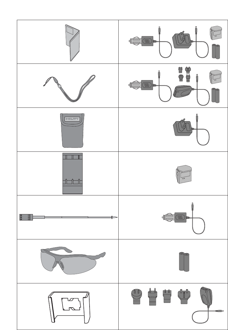
3. Tools and accessories ẅ
Description Designation
Target plate PDA 50
Hand strap PDA 60
Soft pouch PDA 61
Belt clip PDA 62
Measuring extension PDA 70
Charging kit PDA 80
Charging kit PDA 81
Mains adapter PDAW 80-1
Mains adapter PDAW 81-1
Car battery plug PDAW 80/81-2
Charging adapter PDAW 80/81-1
Battery pack PDAW 80/81-3
Laser visibility glasses* PUA 60
* These are not laser safety
glasses and do not protect the
eyes from laser radiation. The
laser visibility glasses restrict
colour vision. These glasses are
therefore not permitted to be
worn by a person driving on a
public road and must not be
used to look directly into the sun
3.1 PDA 50 target plate
The PDA 50 target plate is made of durable
plastic with a special reflective coating. In
poor light conditions it is advisable to use
the target plate for distances above 10 m
(30 ft).
-NOTE-
– For reliable distance measurements the
laser beam should be perpendicular to
the target plate whenever possible. If this
is not the case, the laser spot on the tar-
get plate may not be in the same plane
as the target point and the distance
measured will be incorrect.
– For very accurate measurements using
the target plate, 1.2 mm (1/20 inch)
should be added to the measured dis-
tances.
3.2 PDA 80/81 charging kits
The PDA 80 and PDA 81 charging kits
enable use of the range meters with
rechargeable cells. Battery charging time is
approx.12 hours for fully discharged cells.
However, within the first 15 minutes, the
cells are charged with sufficient current for
150–200 measurements.
Please also refer to the description of bat-
tery charging in section 6. “Getting start-
ed”.
Contents of PDA 80 charging kit
– Mains adapter 100–240 V AC with
2-pole Europlug
– Car battery plug
– Charging adapter for range meter
– 2 rechargeable battery cells (NiMH)
Contents of PDA 81 charging kit
– Mains adapter 100–240 V AC with 4
interchangeable plugs for US, GB, AUS,
EU.
– Car battery plug
– Charging adapter for range meter
– 2 rechargeable battery cells(NiMH)
3.3 PDAW 80-1 mains adapter
The mains adapter is an integral part of the
charging kit. It is equipped with a two-pin
plug. The mains adapter transforms the
power from alternating current to direct

7
3. Werkzeuge und Zubehör
current which is used to charge the batter-
ies. The mains adapter automatically
adjusts itself to suit an AC voltage between
100–240 V and 50–60 Hz. The mains
adapter has been specially designed to
supply current to the charging adapter.
-NOTE-
Battery chargers or mains adapters with
other voltage outputs, such as those for
mobile phones, may not be used. Use of
other battery chargers or mains adapters
may damage the range meter.
3.4 PDAW 80/81-2 car battery plug
The car battery plug is an integral part of
the PDA 80/81 charging kit. It can be
inserted into a vehicle cigarette lighter or
into sockets of the same design. This
adapter has a special design and trans-
forms the 12–24 V direct current of a vehi-
cle battery into a voltage suitable for the
charging adapter.
A light-emitting diode (LED) is incorporat-
ed in the adapter to indicate correct con-
nection for charging. An additional fuse in
the adapter’s front section provides protec-
tion against voltage peaks.
-NOTE-
As the car battery plug has been especially
designed to charge the NiMH batteries of
the PD 38, it may not be replaced by other
types of car battery plugs.
3.5 PDAW 80/81-1 charging adapter
The respective mains adapter supplies cur-
rent to the charging adapter. Prior to
charging the battery, the side flange con-
nections should be carefully checked.
3.6 PDAW 80/81-3 battery pack
The battery pack consists of two recharge-
able, 1.2 V NiMH cells with a capacity of
approx.1800 mAh. The battery pack
remains in the battery compartment while
being charged.
-NOTE-
– There is virtually no “memory effect”
with this type of battery and the charging
process used.
The charging process can be interrupted
at any time without damaging the battery
cells.
– Other brands of rechargeable batteries
can be used. It must be ensured, howev-
er, that the batteries have a similar
capacity of approx. 1800 mAh.
3.7 PDAW 81-1 mains adapter
The PDAW 81-1 mains adapter is virtually
identical to the PDAW 80-1 mains adapter.
The only difference is the type of mains
plugs (interchangeable plugs).
3.8 PUA 60 laser visibility glasses
The laser visibility glasses clearly improve
the visibility of the laser beam (spot).
3.9 PDA 62 belt clip
The belt clip is made from durable plastics
and is quickly and easily fixed to the belt
using the snapper. The range meter snaps
into position for carrying and easily detach-
es when needed.
3.10 PDA 70 measuring extension
The measuring extension is made from alu-
minium and is equipped with a nonconduc-
tive plastic grip.
The range meter attaches to the measuring
extension with the help of the belt clip.
The rear reference is then extended by
1.270 m/50 inches. Please also refer to
section “7.Operation” for more informa-
tion on how to change the reference setting
when using the measuring extension.
3.11 PDA 66 holder
The PDA 66 holder joins the PDA/MDA and
PD 38 as one unit. The smaller part can be
attached to a solid surface on the rear of
the PDA/MDA. The PD 38 can then be
clipped into the holder.

4. Technical data
4. Technical data
Power supply
3V DC
Type: AA (LR6, AM3, Mignon)
Standard: two alkaline batteries
Optional: rechargeable NiMh batteries
Battery status indicator
Battery display with four segments
showing 100%, 75%, 50% and 25%
charged
All segments deleted = discharged
battery
Measuring range
0.05 m to 200 m (2 in to 600 ft)
0.05 m (2 in) from the front edge
Max. distance resolution 750 m
(2,500 ft)
Typical measuring range without tar-
get plate:
– Drywall panel, white 70 m (210 ft)
– Concrete, dry 50 m (150 ft)
– Brick, dry 50 m (150 ft)
The maximum range depends on:
– Reflectivity of the target surface
– Ambient light conditions
In case measurements are not possi-
ble, use the Hilti PDA 50 target plate.
Accuracy
±1.5 mm (±1/16 in) is typical for
individual and continuous measure-
ments **
** The measuring accuracy is affected
by ± (1.5 mm + 20 ppm)/± (1/16 in
+20 ppm) due to atmospheric condi-
tions. This effect is typically noticeable
at distances > 100 m (> 300 ft).
Smallest unit displayed
1 mm (1/16 in)
Beam diameter
< 6 mm @ 10 m (< 0.2 in @ 30 ft)
< 30 mm @ 50 m (< 1.2 in @ 150 ft)
< 60 mm @ 100 m (< 2.4 in @ 300 ft)
Basic operating modes
Single measurement
Continuous measurement
Calculation/functions
Display
Illuminated liquid-crystal display
showing operating status and battery
status
LaserVisible, 620–690 nm, laser class 2
(IEC60825-1: 2003,
CFR 21 § 1040 [FDA])
output power: < 1 mW
Automatic time-out
Laser: 1 min.
Range meter: 10 min.
Battery life at 25 °C (77 °F)
Max. number of measurements
with single set of batteries
(laser switched on for 10 sec.)
Alkaline: 8,000–10,000
NiMH: 6,000– 8,000
Operating temperature
–10 °C…+ 50 °C (14 °F… 122 °F)
Storage temperature
–30 °C…+ 70 °C (–22 °F… 158 °F)
Protection class
Dust and splash-proof, IP 54 as
per IEC529 standard
Weight
220 g/0.48 lb (without batteries)
Dimensions
120 (L) x 65 (W) x 28 (H) mm
4.7" (L) x 2.5" (W) x 1.1" (H) in
8

9
5. Safety information
5. Safety information
5.1 Basic safety information
In addition to the safety precautions listed
in the individual sections of these operating
instructions, the following points must be
strictly observed at all times.
5.2 Misuse
The range meter and its accessories can be
a source of hazard if they are not used
properly or not used for the intended pur-
pose by untrained people.
– Do not use the range meter without suit-
able prior instruction.
– Do not render any safety devices ineffec-
tive and do not remove information and
warning notices.
– Have the range meter repaired only at a
Hilti service center. Unauthorized open-
ing of the range meter may cause the
emission of laser radiation in excess of
class 2.
– Tampering with or modification of the
range meter is not permissible.
– Use only genuine Hilti accessories and
auxiliary tools in order to avoid the risk
of injury.
– Do not use the range meter in atmos-
pheres where there is a risk of explosion.
– Use only a clean, soft cloth for cleaning.
If necessary, moisten the cloth slightly
with pure alcohol.
– Keep the range meter out of the reach of
children.
– Measurements taken to plastic foam
materials, such as polystyrene foam, or
to snow or other strongly reflecting sur-
faces, may be inaccurate.
– Taking measurements to surfaces with
low reflectivity surrounded by areas with
high reflectivity may lead to measure-
ment errors.
– Measurements taken through panes of
glass or other objects may be inaccurate.
– Rapid changes of the measuring condi-
tions, e.g. persons walking through the
laser beam, may lead to measurement
errors.
– Do not direct the range meter towards
the sun or other sources of bright light.
– Do not use the range meter as a levelling
tool.
– Check the range meter before taking
important measurements and after it has
been dropped or subjected to other
mechanical stressing.
– Check the setting of the measuring re-
ference before measuring.
5.3 General safety precautions
Check the range meter for possible damage
before use. If the range meter is found to
be damaged, have it repaired at a Hilti serv-
ice centre. The accuracy of the range meter
must be checked after it has been dropped
or subjected to other mechanical stressing.
– When the range meter is brought into a
warm environment from very cold condi-
tions, or vice versa, allow it to become
acclimatised before use.
– Although the range meter is designed for
the tough conditions of jobsite use, as
with other optical instruments (binocu-
lars, spectacles, cameras, etc.) it should
be treated with care.
– Although the range meter is protected to
prevent entry of dampness, it should be
wiped dry each time before being put
away in its transport container.
– As a precaution, check the settings you
have made before using the range meter.
– When using the circular bubble level
(bull's eye) for alignment, only look at
the range meter from the side.
10
5. Safety information
5.4 Proper organization of workplace
– Secure the area in which you are meas-
uring. When setting up the range meter,
take care to avoid directing the beam
toward yourself or other people.
– Avoid unfavourable body positions when
working on ladders or scaffolding. Make
sure you have a stable stance and avoid
danger of overbalancing at all times.
– Measurements taken through panes of
glass or other objects may be inaccurate.
– Use the range meter only while observing
the specified operating conditions, i.e.
not directed towards a mirror, stainless
steel, polished stone, etc.
– Observe the accident prevention regula-
tions applicable in the country in which
you are working.
– Use the PDA 66 holder only together with
the PDAs/MDAs recommended by Hilti
and only in conjunction with the PD 38.
– Check to ensure that your PD 38 com-
municates only with your PDA/MDA, and
vice versa.
5.4.1 Electromagnetic compatibility
Although the range meter complies with
the strict requirements of the relevant
guidelines, Hilti cannot entirely rule out the
following possibilities:
– The range meter might cause interfer-
ence to other equipment, e.g. aircraft
navigational equipment.
– The range meter might be subject to
interference caused by powerful radia-
tion, which can then lead to incorrect
operation. Check the readings for plausi-
bility when measuring in these conditions
or if you are unsure of the results.
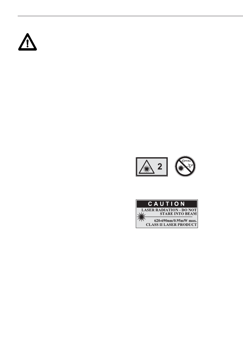
5.4.2 Laser classification
The range meter conforms to laser class 2
based on the IEC60825-1: 2003; standard
and class II based on CFR 21 § 1040
(FDA). These range meters may be used
without need for further protective meas-
ures. The eyelid closure reflex protects the
eyes if a person looks into the beam unin-
tentionally for a brief moment. The eyelid
closure reflex can, however, be negatively
influenced by medication, alcohol or drugs.
Nevertheless, as with the sun, a person
should not look directly into sources of
bright light. The laser beam should not be
directed towards persons.
Laser information plates based on
IEC60825-1: 2003
Laser information plates for the US
based on CFR 21 § 1040 (FDA)
This laser product complies with 21 CFR
1040, as applicable.
5.4.3 Transport
Remove the alkaline or rechargeable batter-
ies whenever transporting the range meter.
11
6. Getting started
6. Getting started
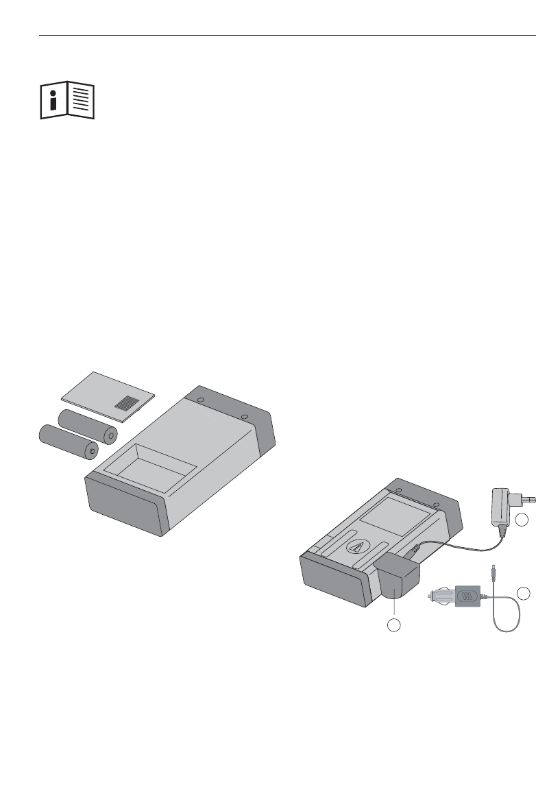
6.1 Inserting alkaline/rechargeable
batteries
-CAUTION-
– Observe the polarity of the batteries.
(refer to symbols inside the battery com-
partment.)
– Make sure the battery compartment is
properly locked.
1.Press the cover of the battery compart-
ment lightly.
2.Slide the cover out and off.
3.Replace the batteries.
-NOTE-
For alkaline batteries
– Always replace a complete set of batter-
ies.
– Do not mix used and new batteries.
– Do not mix batteries of different makes
or types.
– Use only undamaged batteries of an
approved type.
For rechargeable batteries
– Always use rechargeable batteries of the
same make and same type.
– Always use rechargeable batteries of the
same age and charged to the same level.
– New rechargeable batteries are supplied
uncharged and have to be charged prior
to first use.
– Use only 1.2 V NiMH batteries with
1500–2000 mAh capacity.
6.2 Battery charging
6.2.1 Standard battery charging
The charging process ensures that there
will be virtually no “memory effect”. In
view of this, charging can begin at any time
regardless of the level to which the battery
is already charged.
Attach the PDAW 80/81-1 charging adapter
to the range meter ቢ.
For charging, connect either the mains
adapter or the car battery plug ባ to the
charging adapter.
The maximum charging time is 12 hours.
As with many mobile phones, the level of
charging is shown by movement of battery
display segments.
1
2
2
12
6. Getting started
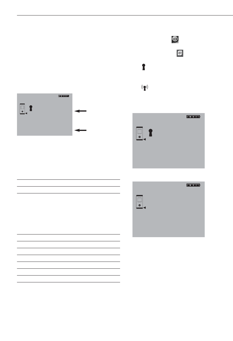
6.2.1.1 Battery charging level display
– The level of charging is indicated by
moving battery status segments
at top right of the display.
– When a battery is fully charged,
(battery fully charged) will be dis-
played.
6.2.1.2 Charging display for unintention-
ally inserted alkaline batteries
– If alkaline batteries are identified, all bat-
tery status segments flash continually to
indicate missing rechargeable batteries.
Additionally, the symbol
shows in the display.
The range meter cannot be switched on.
– If defective or non re-chargeable alkaline
batteries are inserted, the battery display
will flash and, at the same time,
(defective battery) will appear in
the display.
-NOTE-
– The range meter can be switched on and
used at any time while the batteries are
being charged. The battery charging
process stops when the range meter is
switched on and the laser activated.
– Rechargeable batteries discharge if they
are stored for a long time. The battery
charging process terminates after
1minute when charging deeply dis-
charged or defective rechargeable batter-
ies and the display switches off. In this
case, the charging process can be re-
started only by disconnecting the range
meter from the mains adapter or by
removing/replacing the rechargeable bat-
teries.
– Keep the range meter in a safe place.
dEF
Accu
Accuno
Full
Accu
6.2.2 Fast battery charging
The charging process ensures that 15 min-
utes of charging with the PDAW 80/81-2
car battery plug provides the battery with
enough power for a further 150 to 200
measurements.
This process in combination with the car
battery plug is of particular advantage in
situations where the user needs the range
meter ready for use quickly.
6.3 Switching the range meter on and off
The range meter is switched on or off by
pressing the “On/Off” button.
After switching on, the range meter is in
the basic display mode.
6.3.1 Initial distance measurement
Press the “Measure” button once.
This will switch on the range meter and the
laser beam if the range meter was prvious-
ly switched off.
If the range meter is already switched on,
this will activate the laser beam.
Aim the visible laser spot at a target about
3 to 10 (10–30 ft) meters away.
Press the “Measure” button again.
The distance will be shown in less than
1second, e.g. 5.489 m (16.296 ft).
You have taken the first distance measure-
ment with the PD 32 range meter.
m
5.489
13
6. Getting started
6.4 Settings
6.4.1 Activating the settings menu
The menu is activated by pressing the
“On/Off” button for about 2 seconds while
the range meter is switched off.
The menu allows beep, units and Bluetooth
settings to be made.
6.4.2 Menu/Beep
The “Plus” button is used to switch
between the “On” and “Off” modes.
Setting Option
Beep On
Off
6.4.3 Menu/Units
The “Minus” button is used to switch
between the units, as shown below.
Setting Distance Area Volume
mmeters m2m3
mm millimeters m2m3
ft feet (decimal) feet2feet2
yd feet (decimal) yard2yard3
in inch (decimal) inch2inch3
in 1/8 feet & inch 1/8 feet2feet3
in 1/16 feet & inch 1/16 feet2feet3
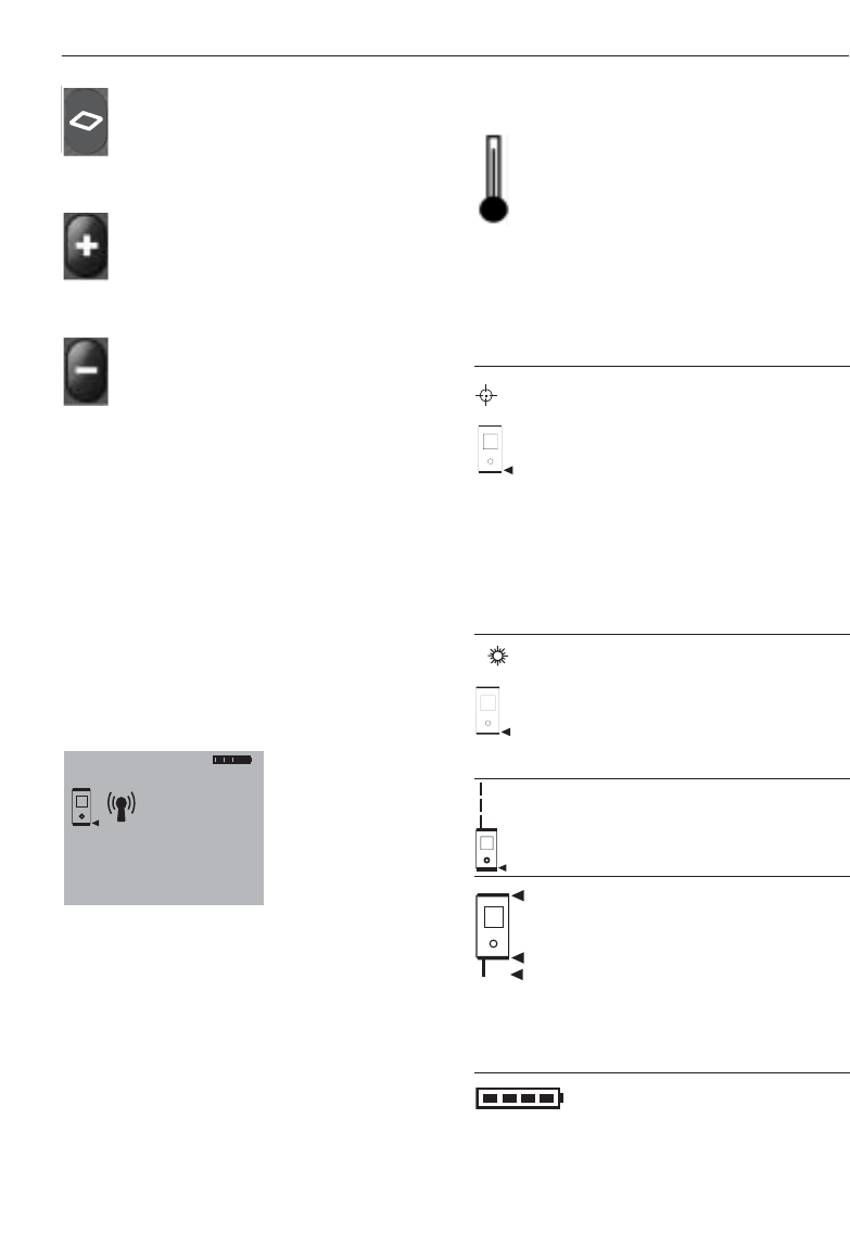
6.4.4 Switching Bluetooth on and off
The menu must be activated with the
“ON/OFF” button beforehand. Refer to
“6.4.1. Activating the settings menu”.
The volume button toggles Bluetooth
between ON and OFF.
The symbol shows the Bluetooth on-
status. Buetooth is switched off when this
symbol is not displayed.
The symbol indicates an active con-
nection to a PDA/MDA running the Hilti
PD 38 software.
-NOTE-
The PD 38 connects only to devices run-
ning the Hilti PD 38 measuring application
on the Windows CE operating system or
wherever a Hilti Bluetooth interfacing ver-
sion is installed and active (typical
PDA/MDA).
6.4.4 Terminating the menu
The menu is terminated by pressing the
“On/Off” button. All settings displayed will
be saved.
Beep
Units
MENU
on
m
BEEP
Unit
MENU
on
m
BEEP
Unit
Bluetooth switched on
MENU
on
m
BEEP
Unit
Bluetooth switched off
7.1.3 Measuring extension as reference
–Tool is switched off.
Press the measuring
reference button and the
+on/off button simultaneously.
+The measuring spike flashes
in the display. The reference
is then set to the end of the
fully
extended measuring
extension.
7.1.3 Measure buttons
“Measure” button
–switches the range meter on
–activates the laser beam for
aiming at the target,
–activates single distance
measurement
–activates and deactivates con-
tinuous distance measure-
ment.
Side “Measure” button
–activates the laser beam for
aiming at the target,
–activates individual distance
measurement
–activates and deactivates con-
tinuous distance measure-
ment.
7.1.4 Function buttons
Calculation functions are activated by
pressing the relevant function buttons.
When a measurement using a function has
been carried out incorrectly or unintention-
ally, the function can be reset at any time
by pressing the same function button again
or any other function button.
Volume
–activates the “volume”
function and deactivates
every other function.
14
7. Operation
7. Operation
7.1 General controls
7.1.1 Control panel
7.1.2 On/off and control buttons
ON/OFF
–switches the range meter
on and off.
Measuring reference point
–switches the measuring
reference between front
and rear.
Display illumination
–switches the display
illumination on and off.
15
7. Operation
Area
–activates the “area” function
and deactivates every other
function.
Plus
–activates the “distance
addition” function and deacti-
vates every other function.
Minus
–activates “distance
subtraction” and deactivates
every other function.
7.2 Display
The display shows the measurements, set-
tings and range meter status.
In the measuring mode, the latest readings
are shown in the lowest display line (result
line) and the prior readings in the lines
above. For functions such as area, volume,
Pythagoras, etc., the measured distances
are displayed in the intermediate lines and
the calculated result appears in the lowest
display line (result line).
m
27.317
5.489
m
m
m
12.349
24.634
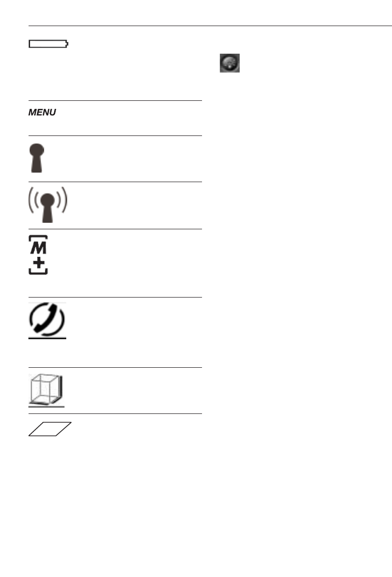
7.2.1 Symbols displayed
Temperature too high
> +50 °C (122 °F)
Action:
Allow the range meter to cool
down.
Temperature too low
< –10 °C (14 °F)
Action:
Warm up the range meter.
Unfavourable signal conditions
Insufficient reflected laser light
Action:
– Observe the minimum measu-
ring distance of > 50 mm
(2 in) from the front edge.
– Clean the lens.
– Take a measurement from
another surface or use the
PDA50 target plate.
Ambient light at target too bright
Action:
– Shade the target from bright
light or use the PDA50 tar-
get plate.
Laser switched on
– Moving broken line
Display reference status
– Front edge
– Rear edge
– Spike
– Spike (flashing) – automati-
cally adds 1.270 m/50 inches
to measurements
Battery status
– 4 segments =100% fully charged
– 3 segments = 75%
– 2 segments = 50%
– 1 segment = 25%
– 0 segments = discharged
16
7.2.2 Display illumination
= Illumination button
The illumination button switches the dis-
play illumination on or off. In the dark or in
very bright light, e.g. sunlight or a strong
spotlight, the display illumination makes it
easier to read the display.
-NOTE-
Display illumination consumes additional
power. If it is used frequently, shorter bat-
tery life must be expected.
7.3 Optical sight
The built-in optical sight is of great benefit
when measuring outdoors and whenever
the laser spot is poorly visible. The optical
sight allows the laser spot to be positioned
on the target accurately even at great dis-
tance. The laser spot is visible in the opti-
cal sight when the range meter is switched
on. If the laser spot is not visible in the
optical sight then either the measurement
has been completed successfully or the
laser beam has switched itself off automat-
ically after the preset time (1 minute).
The optical axis of the sight runs parallel to
the laser beam.
Typical measuring procedure with the
optical sight
– Press the “Measure” button to activate
the laser beam.
– Use the optical sight to aim the range
meter and position the laser spot on the
target.
–Press the measure button or side mea-
sure button and keep the laser spot on
the target until the spot disappears from
the optical sight.
– Read the distance from the display.
7. Operation
Batteries fully discharged
Action:
–Replace batteries.
– Recharge rechargeable
batteries.
Menu activated
Bluetooth is switched on
Bluetooth has established
connection to another device
Historical data mode active
– Displays the previous 5
measurements or complete
functions results including
graphics.
General hardware error
Switch the range meter off
and then back on. If the error
persists, notify the local Hilti
service centre.
Volume measurement active
Area measurement active
7. Operation
Diagram of optical sight
-NOTE-
Use of the optical sight is recommended
for distances above 10 m (30 ft.).
7.4 Measuring distances
Distance measurements can be taken to all
stationary targets without a highly reflec-
tive surface, i.e. concrete, rock, wood,
plastic, paper, etc. The use of prisms or
measuring to highly reflective surface is
not permitted and, if attempted, might fal-
sify the results.
7.4.1 Measuring references
= Reference button
The range meter can measure distances
from three different measuring reference
points.
The measuring reference point can be tog-
gled between the front edge and rear edge
by pressing the reference button on front
left of the range meter. The reference is set
automatically to the end of the spike when
the spike is folded out to the 90° position.
The reference can be set to the end of the
PDA 70 measuring reference extension by
pressing the reference button (top left) and
the on/off button (top right) simultaneously
while the range meter is switched off. The
spike symbol in the display then begins to
blink.
This measuring reference setting for the
PDA 70 can be deactivated by switching
the range meter off and then on again.
Eye
Laser
Sighting
Display Reference position
Front edge
Rear edge
End of spike
PDA70 measuring extension
Spike (flashing) extends by
1.270 m/50 inches
-NOTE-
– If the spike is folded out 180°, the refer-
ence point is always automatically set to
the rear edge.
7.4.2 Measuring distances step by step
The range meter measures distances in a
very short time and, when doing so, shows
various information in the display.
1. Switch on the range meter by pressing
the “On” button.
2. Press the “Measure” button once.
This switches on the red laser beam
which is visible as a laser spot on the
target surface. The display shows this
aiming mode as an animated broken line.
----------
m
LASER
m
----------
17

18
7.4.3.1 Single distance measurement
(“Measure”)
1.Switch on the laser beam by pressing
the “Measure” button.
2.Press the “Measure” button once again.
The measured distance will normally be
shown in the result line in less than a
second.
-NOTE-
Alternatively, the range meter may be
switched on by pressing the “On” button
and the laser then activated by pressing the
“Measure” button.
7.4.3.2 Continuous measurement
Press the “Measure” button for about
2seconds to activate this measuring mode.
When doing so, it does not matter whether
or not the range meter or the laser beam is
switched on or off. The range meter will
always switch to continuous measurement.
During continuous measurement, distances
are updated in the result line at the rate of
about 8 to 15 measurements every second.
The rate of measurement depends on the
reflectivity of the target surface.
If the beep signal is active, continuous
measurement is indicated by a beep.
The measuring process is stopped by
pressing the “Measure” button once again.
On doing so, the last valid distance meas-
urement will be shown in the result line in
the display.
-NOTE-
Continuous measurement is possible in all
situations where distances can be mea-
sured. This applies also to functions, such
as areas and volumes.
7. Operation
3. Aim at the target.
4. Press the “Measure” button once again
to measure the distance.
The result appears in the result line nor-
mally in less than a second. The laser
beam switches off.
If further measurements are taken, up to
three previously determined distances are
shown in the intermediate result lines, i.e.
atotal of the last four measured distances
are shown.
7.4.3 Measuring mode
Two different distance measuring modes
are available. These are single distance
measurement and continuous distance
measurement. The continuous measure-
ment mode is used for setting out given
distances or offsets and is also used where
distance measurements are more difficult,
e.g. to corners, edges, niches, etc.
m
27.317
5.489
m
m
m
12.349
24.634
m
5.489
19
7. Operation
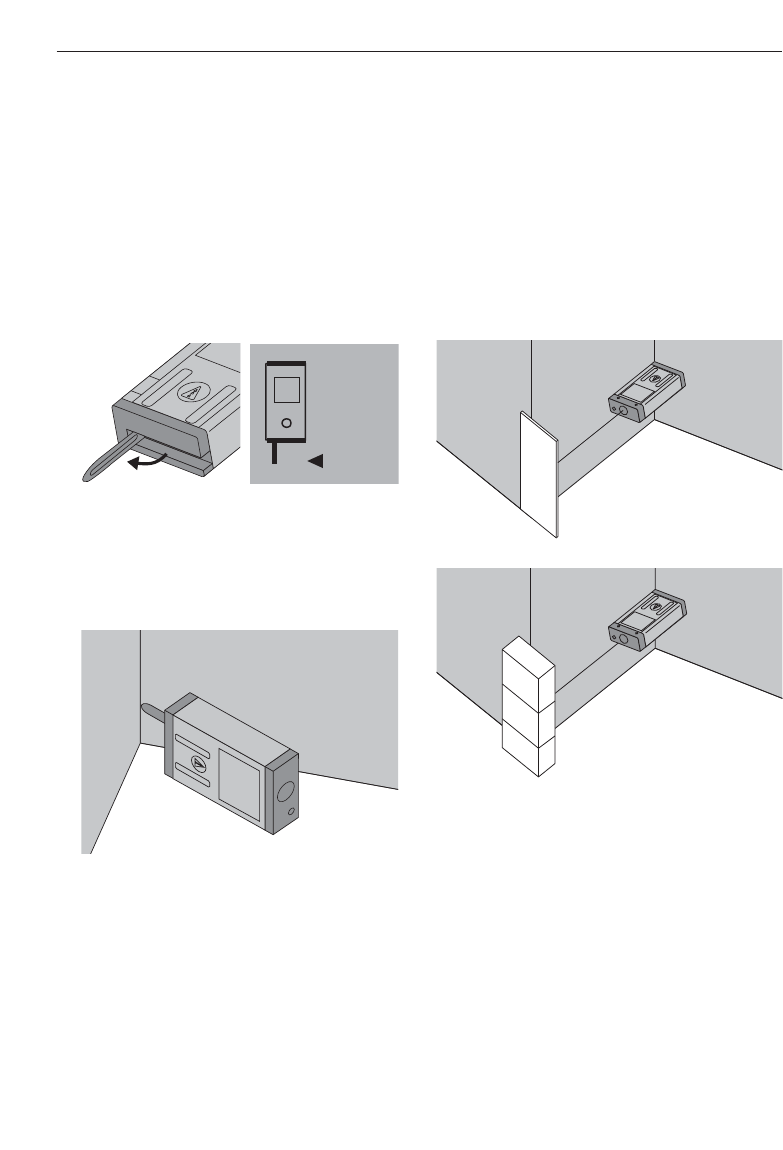
7.4.4 Measuring from corners
The spike is used when measuring diago-
nally across rooms or from inaccessible
corners.
1. Fold out the spike 90°.
This automatically sets the measuring
reference to the end of the spike. The
range meter takes the extended reference
point into account and corrects the
measured distances accordingly.
2. Position the range meter with the spike
at the desired starting point for the
measurement and aim towards the tar-
get.
3. Press the “Measure” button. The meas-
ured distance appears in the display.
7.4.5 Measuring with the aid of target
objects
When taking measurements to outside cor-
ners, e.g. on buildings, perimeter fences,
etc., boards, bricks or other suitable
objects can be used as the target.
Use of the PDA 50 target plate is recom-
mended for long distances and in unfa-
vourable light conditions, e.g. strong sun-
light.
7.4.6 Measuring in bright conditions
The PD 38 has a built-in optical target
sight. When measuring to very bright sur-
faces, the laser spot is often not visible.
Thanks to the laser spot superimposed in
the optical sight, you can always clearly
and reliably aim at the target.
We recommend use of the PDA 50 target
plate for long distances and bright light
conditions.
20
7.4.10 Taking measurements to transpar-
ent surfaces
It is not possible to measure distances to
transparent materials, e.g. liquids, poly-
styrene foam, etc. This is because light
penetrates these materials and therefore
measuring errors may occur. Measuring
errors may also occur if measurements are
taken through glass or if obstructions are
present within the line of the laser beam.
7.4.11 Measuring ranges
7.4.11.1 Increased distances
– Taking measurements in the dark, at
dawn, dusk and to shaded targets or with
the front of the range meter shaded, gen-
erally leads to an increase in the measur-
ing range.
– Taking measurements to the PDA 50
target plate also results in an increase in
the measuring range.
7.4.11.2 Reduced distances
– Taking measurements in very bright
ambient light, e.g. in sunshine or a very
bright spotlight etc, can lead to a reduc-
tion in range.
– Taking measurements through glass or
other objects in the target beam can lead
to reduced measuring range.
– Taking measurements to matt green, blue
or black, wet or shiny surfaces can lead
to reduced measuring range.
7. Operation
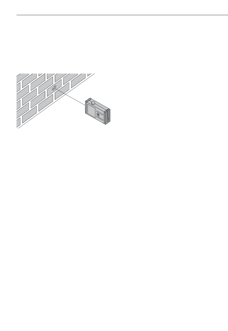
7.4.7 Taking measurements to rough sur-
faces
When measuring to rough surfaces, e.g.
coarse render, stucco, etc, an average dis-
tance value is measured with the centre of
laser spot weighted higher than the edges
of the laser spot.
7.4.8 Taking measurements to round or
inclined surfaces
If the laser beam strikes the target surface
at a very narrow angle, the light reflected
may be inadequate.
Conversely, too much light may be reflect-
ed toward the range meter in certain situa-
tions where the laser beam strikes the tar-
get perpendicularly.
We recommend use of the PDA 50 target
plate in both of these situations.
7.4.9 Taking measurements to wet or
shiny surfaces
As long as the range meter can be aimed
towards the surface, the distance to the
target will be reliably measured. In the case
of highly reflective surfaces, a reduction in
range or measurement of the distance to
the actual point of reflection must be
expected.
21
8. Applications and functions
8. Applications and functions
The individual steps within all functions are
supported by the graphical display.
-NOTE-
– Continuous measurement can be used
within all functions where single measure-
ments are possible.
– If measuring errors occur during conti-
nuous measurement or if continuous
measurement is stopped by pressing the
“Measure” button again, the last valid
distance will be shown.
All PD 38 on-board functions such as area,
volume, plus and minus are disabled while
a Bluetooth connection is active.
An active connection is indicated by the
symbol.
8.1 Measurement data memory
The range meter continuously saves the
measured values and the results of calcula-
tions while measuring.
8.1.1 Saving measurements
When measuring several distances, up to
three previous distances are displayed in
the intermediate result lines. This means
that, in total, the last four measured dis-
tances are displayed or saved.
4. measured value
3. measured value
2. measured value
1. last measured
value
8.1.2 Historical data memory
The range meter saves the last five meas-
urements or calculations including the
graphics. This saved data can be shown
consecutively in the display by pressing the
plus and minus buttons immediately after
switching on the range meter with the
on/off button (as long as no function has
been carried out or distance measurement
taken).
The symbol “Historical data mode active”
shows the data stored in the memory.
Example of the display of a saved volume
measurement:
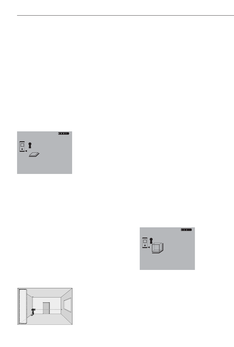
8.2 Area measurement
Areas can be determined easily and quickly.
Press the “Area” function button. This
switches the laser beam on – ready for
measuring.
The individual steps for determining an area
are supported by a corresponding graphic
display. To determine the floor space of a
room, for example, the procedure is as fol-
lows:
ab
= a . b
m
1669.783
5.489
m
m
m
12.349
24.634
3
M
+
22
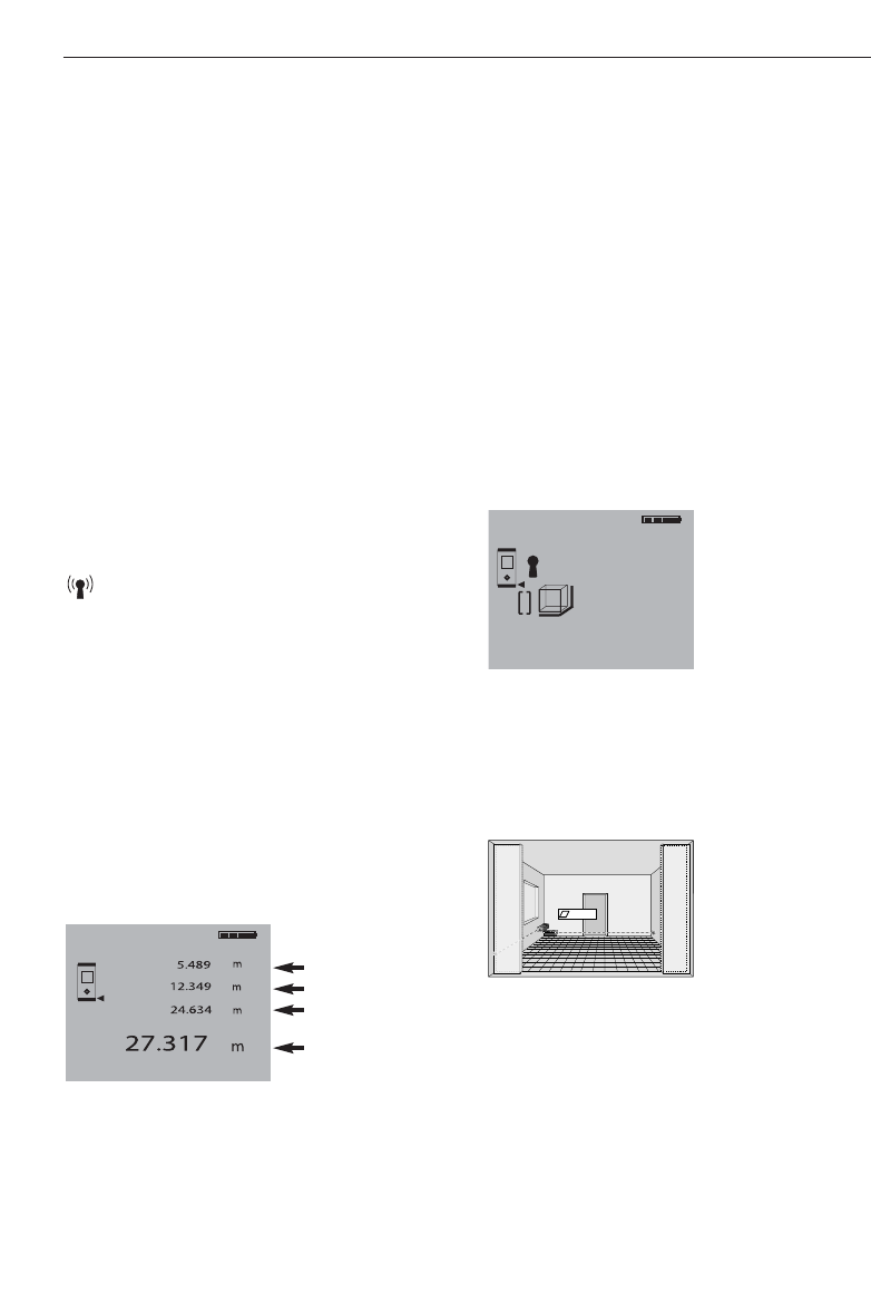
The individual steps for determining a vol-
ume are supported by a corresponding
graphic display. To determine the volume
of a room, for example, the following pro-
cedure must be followed:
1. At the start of the volume function, the
laser beam is switched on.
2. Aim the range meter towards at the tar-
get.
3. Press the “Measure” button.
The room width will be measured and
shown.
4. After this, the graphic display will auto-
matically request measurement of the
room length.
5. Aim the range meter at the next target
to obtain the room length.
6. Press the “Measure” button.
The room length will be measured.
7. After this, the graphic display will auto-
matically request measurement of the
room height.
8. Aim the range meter at the next target
to obtain the room height.
9. Press the “Measure” button.
The room height will be measured, the
volume immediately calculated and the
result shown in the result line.
All three distances required to calculate the
volume appear in the intermediate result
lines and can be conveniently noted after
the measurements and the calculation.
-NOTE-
To determine another volume, press the
“Volume” function button again.
m
1669.783
5.489
m
m
m
12.349
24.634
3
8. Applications and functions
1. At the start of the area function, the
laser beam is switched on.
2. Aim the range meter at the target.
3. Press the “Measure” button.
The room width will be measured and
shown.
4. After this, the graphic display will auto-
matically request measurement of the
room length.
5. Aim the range meter at the next target
to obtain the room length.
6. Press the “Measure” button.
The second distance will be measured,
the area immediately calculated and the
result shown in the result line.
Both distances required to calculate the
area appear in the intermediate result lines
and can be conveniently noted after the
measurements and the calculation.
-NOTE-
To determine another area, press the
“Area” function button again.
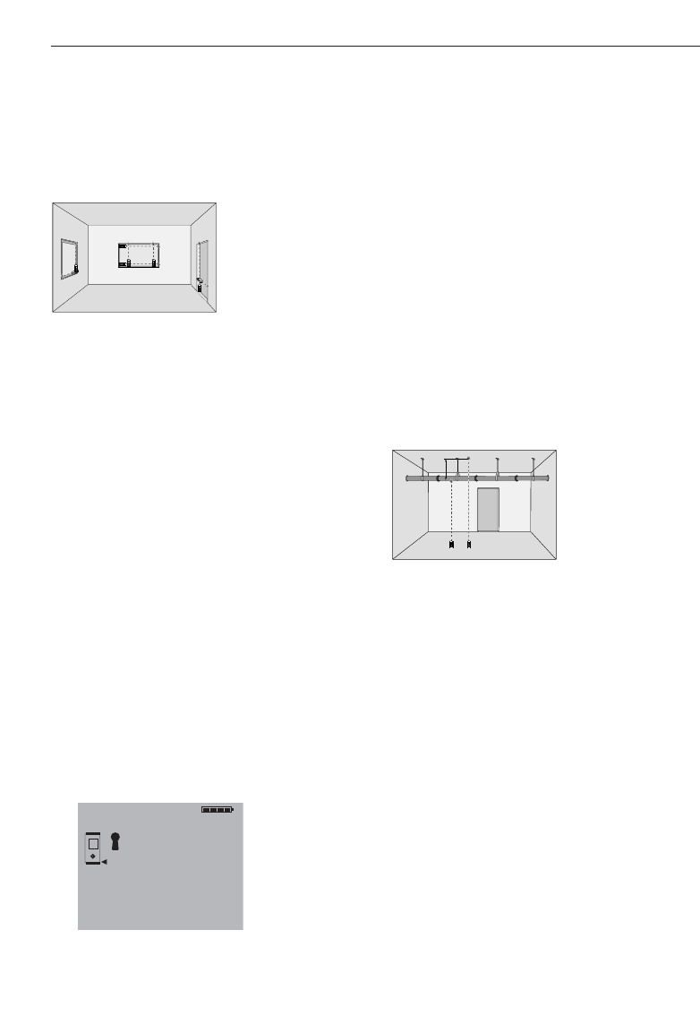
8.3 Volume measurement
Volumes can be determined in one measur-
ing operation.
Press the “Volume” function button. This
switches the laser beam on – ready for
measuring.
MEN
x
+
-
I
=
PD 25
m
67.784
5.489
m
m
12.349
2
23
8. Applications and functions
8.4 Adding distances
Individual distances can be conveniently
added. This is useful for determining the
total length of the inner face of door or
window openings or for adding several
partial distances that form a perimeter.
1. Press the “Measure” button.
(The laser beam will be switched on).
2. Direct the range meter towards the tar-
get.
3. Press the “Measure” button.
The first distance will be measured and
shown. (The laser will be switched off.)
4. Press the “Plus” button to add the next
distance. The first distance will appear
in the middle (intermediate) result line
and a plus sign in the lower line. (The
laser beam will be switched on.)
5. Aim the range meter at the next target.
6. Press the “Measure” button.
The second distance will be measured
and shown in the lower (intermediate)
result line. The calculation result will
appear in the result line at the same
time.
The current total of the distances is always
shown in the result line.
This procedure can be repeated until all
distances have been added.
17.838
m
m
12.349
+5.489
m
MEN
x
+
-
I
=
PD 25
MEN
x
+
-
I
=
PD 25
MEN
x
+
-
I
=
PD 25
MEN
x
+
-
I
=
PD 25
MEN
x
+
-
I
=
PD 25
MEN
x
+
-
I
=
PD 25
To terminate the addition of distances, sim-
ply measure a distance without first press-
ing the “Plus” button. The previous three
measurement and calculation results will
be shown in the intermediate displays.
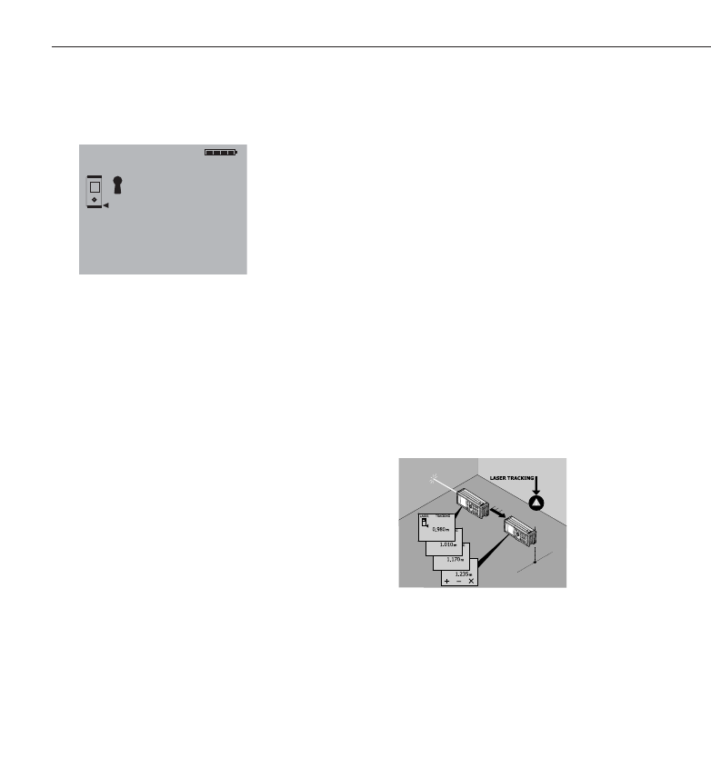
8.5 Subtracting distances
Individual distances can be conveniently
subtracted from each other. This is useful
for determining, for example, offsets to
inaccessible places or the distance from
the underside of a pipe to the ceiling. To
do so, the distance from the floor to the
underside of the pipe is subtracted from
the distance from the floor to the ceiling. If,
additionally, the pipe diameter is deducted,
the result is the distance from the top of
the pipe to the ceiling.
1. Press the “Measure” button.
(The laser beam will be switched on.)
2. Aim the range meter at the target.
3. Press the “Measure” button.
The first distance will be measured and
shown. (The laser beam will switch off.)
4. Press the “Minus” button for subtrac-
tion.
The first distance will appear in the
middle (intermediate) result line and a
minus sign in the lower line. (The laser
beam will switch on.)
5. Aim the range meter at the next target.
6. Press the “Measure” button.
The second distance will be measured
and shown in the lower (intermediate)
result line. The result of the subtraction
will appear in the result line.
8
79
5
46
2
13
.
0=
C
I
PD 28
?!+
x
8
79
5
46
2
13
.
0=
C
I
PD 28
?!+
x
?
8.6 Setting out
Predetermined dimensions, such as for
installing drywall tracks, can be set out and
marked with the range meter.
The continuous measurement mode is
used when transfering dimensions from
drawings. (See also section 7.4.3.2 “Con-
tinuous measurement.”)
Hold the “Measure” button pressed for
approx. 2 seconds to activate the continu-
ous measurement mode. When doing so, it
does not matter whether the range meter
or the laser beam are switched on or off.
The range meter always switches to the
continuous measurement mode. Move the
range meter slowly until the desired dis-
tance is reached or appears in the display.
Press the “Measure” button once again to
end the continuous measurement mode.
24
8. Applications and functions
The current difference between dis-
tances is always shown in the result
line.
This procedure can be followed until all
distances have been subtracted.
To terminate the subtraction of distances,
simply measure a distance without first
pressing the “Minus” button. The previous
measurement and calculation results will
be shown in the intermediate displays.
0.625
m
m
3.947
-3.322
m

25
9. Measuring using a Bluetooth
connection
-NOTE-
Only PDAs/MDAs running the Windows CE
operating system are compatible with the
PD 38.
9.1 Setting up the PDA/MDA
If you intend to use a new PDA/MDA out of
the box for the first time with a PD 38, it is
required to first connect the PDA/MDA to
the PC. Please follow the user instructions
for the PDA/MDA which describe how to
make a PC connection and how to set up
the PDA/MDA for data exchange with a PC.
Section 9.1.1 can be used as a general
guideline. Please refer to the instructions
supplied with your PDA/MDA for more
detailed information.
If your PDA/MDA running the Windows
CE operating system is already set up for
data exchange using “Active Sync”, please
go to section 9.2 “Establishing a
connec-
tion between PDA/MDA and PD 38”.
9.1.1 Installation and connection of
PDA/MDA and PC
General step-by-step instructions for con-
necting a PDA/MDA and a PC:
1. The CD-ROM supplied with the PDA/MDA
contains the Windows connection soft-
ware Active Sync. Install this software
on the PC in accordance with the instruc-
tions of the PDA/MDA manufacturer.
2. Connect the PDA/MDA docking station
to the PC with a USB cable.
3. Place the PDA/MDA in the docking sta-
tion and switch it on.
4. Active Sync should activate itself auto-
matically on the PC after the PDA/MDA
has been placed in the docking station
and switched on. Alternatively, Active
Sync can be started manually on the PC.
9. Messen mit Bluetooth-Verbinduung
5. Follow the instructions of “Active Sync” to
establish a guest partnership with the PC.
-NOTE-
Read the instructions for the PDA/MDA
carefully about setting up the connection to
the PC using the Windows software “Active
Sync”.
9.1.2 Installation of Hilti PD 38 application
software on a PDA/MDA
Installation of Hilti PD 38 application soft-
ware on a PDA/MDA:
Before beginning the installation, it is
essential that the connection between the
PDA/MDA and the PC has been established
by installing the Active Sync Windows PC
software.
1. Place the PDA/MDA in the docking sta-
tion and switch it on.
2. Follow the instructions of “Active Sync” to
establish a guest partnership with the PC.
3. Insert the Hilti PD 38 CD-ROM in the
CD-ROM drive. The installation will start
automatically.
Please follow the instructions on the
screen.
Remove the PDA/MDA from the docking
station after successful installation of the
Hilti PD 38 application software.
9.2 Establishing a connection between
PD 38 and PDA/MDA
Before the connection can be established it
is essential that the Hilti PD 38 application
software has been successfully installed on
the PDA/MDA.
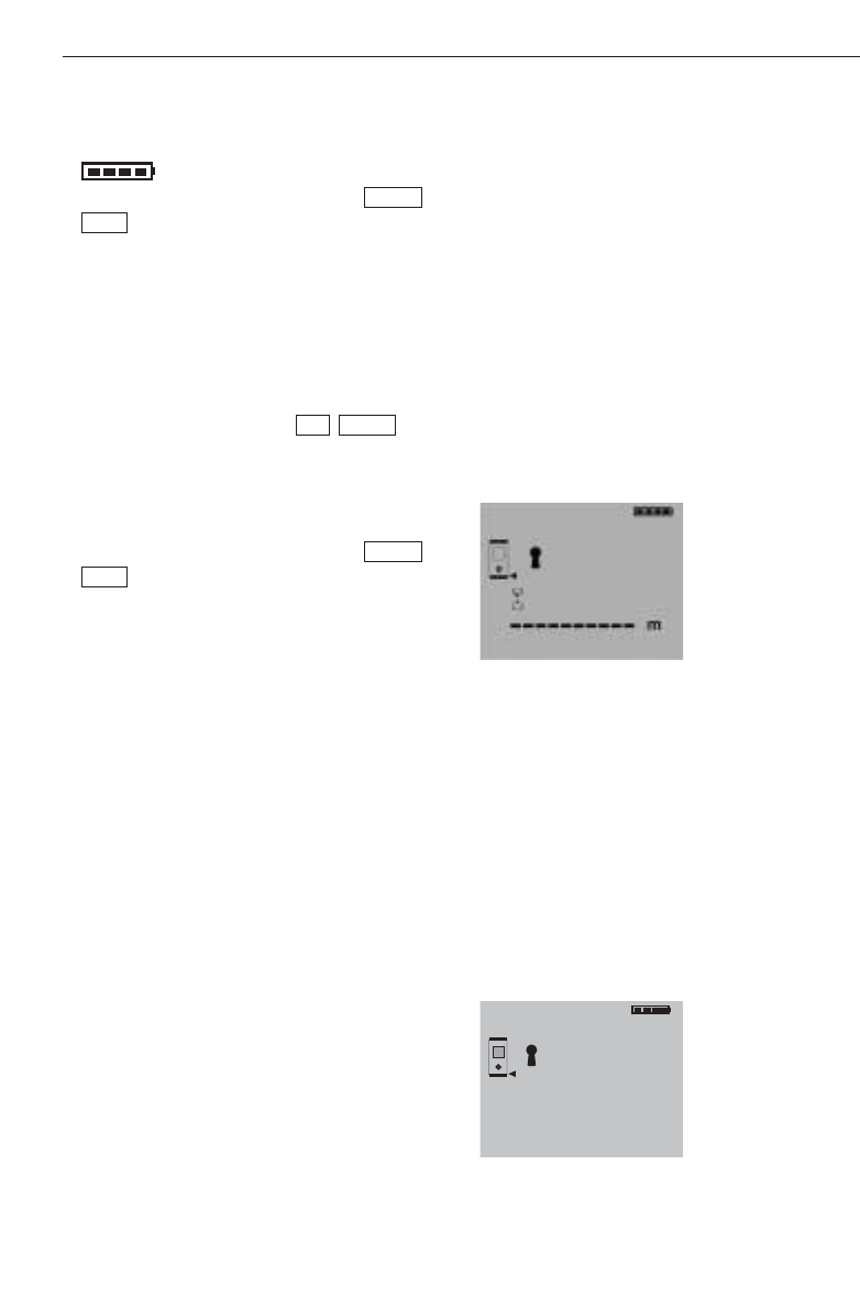
1. Switch on the PD 38 by pressing the
“On” button . Check that the sym-
bol is displayed. If this symbol is not
displayed, check that Bluetooth is
switched on (refer to section 6.4.4
“Switching Bluetooth on and off”).
26
9. Measuring with a bluetooth connection
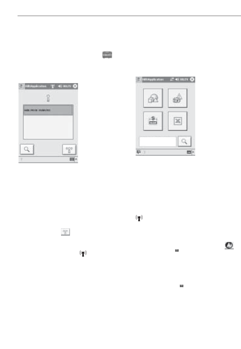
2. Switch on the PDA/MDA and proceed as
follows:
– Select Windows Start
– Select Programs
– Select the Hilti PD 38 symbol
The Hilti PD 38 application then starts
with the following screen:
A search for all nearby Hilti PD 38 laser
range meters with active Bluetooth mode
will start as soon as the above screen is
shown. The search can take up to 2 minu-
tes. The displayed list shows the serial
numbers of all PD 38s found. Select the
serial number of your PD 38. The serial
number can be found on the back of the
PD 38. Press the button to make the
connection.
The connection is established after approx-
imately 30 seconds. The symbol pro-
vides verification of a successful connec-
tion.
3. On successful connection between
PDA/MDA and PD 38 the display of the
PDA/MDA changes to the start-up dis-
play of the Hilti PD 38 applications and
shows the serial number of the connec-
ted PD 38 in the lower window.
9.3 Measuring using Bluetooth connec-
tion to PDA/MDA
-NOTE-
During an active Bluetooth connection all
PD 38 on-board functions such as area,
volume, plus and minus are disabled. The
symbol indicates an active Bluetooth
connection.
Distance measurement functions using the
PDA/MDA are shown either with the
icon or with the icon.
Distance measurement can always be trig-
gered from the PDA/MDA if one of above
symbols is available or by pressing the
measuring button on the PD 38 laser
range meter.
Hilti PD 38 15805701

10. PDA/MDA Windows CE application Hilti PD 38
10. PDA/MDA Windows CE with
Hilti PD 38 application
The Hilti PD 38 application is installed on a
PDA/MDA as described in chapter “9.1.2
Installation of Hilti PD 38 application soft-
ware on a PDA/MDA”. The program con-
tains four major functions, Image Sketch,
Line Draw, Data Table and Formulary. The
measurements are transferred to the par-
ticular function by wireless communication
– all measurements can also be entered
manually.
-NOTE-
Further instructions about the separate
functions can be found in the help texts for
the particular function on the PDA/MDA.
1. “Image Sketch”
Some PDAs and most MDAs are equip-
ped with a digital camera which allows
photos to be taken of a particular object
on the spot, e.g. window, door, room, etc.
Existing digital images can also be trans-
ferred to the PDA/MDA. Measured
lengths, shown as lines with dimensions,
can be added directly to the photos
taken on the spot with the PDA/MDA or
those transferred from the PC.
These photos with measurements can
then be printed out or transferred to the
PC for further use.
Using an MDA, the photos can be sent
as an E-mail from the photo location, for
example, to an office.
All relevant output formats, e.g. bitmap
(*.bmp) or JPEG (*.jpg) can be trans-
ferred to the PC.
2. “Line Draw”
This drawing function creates outline
plans – combining measuring and scale
drawing – on the spot.
Other possible uses are the design and
drawing of non-rectangular objects and
features.
The calculation of the area of enclosed
geometrical figures is also possible, even
when several are joined together.
All common CAD output formats are
supported for transfer to the PC
– Felixcad (*.flx)
– AutoCad DXF (*.dxf) for release 12 up to
release 14 and AutoCad 2000/2002
– AutoCad Format (*.dwg) for release 12
up to release 14 and also AutoCad
2000/2002
All drawings can also be transferred as
pixel data to the PC
– Bitmap (*.bmp)
– JPEG (*.jpg)
This allows the drawings to be displayed
on a PC without a CAD system.
3. “Data Table”
The Data Table function creates a table fully
compatible with Windows Excel, with
measurements entered directly in the
appropriate cells.
However, measurements are activated
(from the PDA/MDA or from the PD 38)
only when the “Hilti Measuring Interface”
in the lower right-hand window has been
activated.
Once active, the symbol is shown in
the lower section of the PDA/MDA display.
-NOTE-
Take note of the units used in Excel as
these are not saved.
27

10. PDA/MDA Windows CE application Hilti PD 38/11. Data transfer from PDA/MDA to PC
Different options exist when using the
data table
– The data table can be used with the cells
simply containing measurements, with-
out any line or column description.
– The structure of the table can be estab-
lished on the PDA/MDA, i.e. the lines and
columns are pre-defined according to the
measurement needs and the measure-
ments entered into the respective cells.
– The structure of the table can be defined
and established in Windows Excel on the
PC, i.e. a relevant structured measure-
ment table fully pre-defined on the PC.
This can also contain formats and formu-
las which can be used as checks on the
spot.
-NOTE-
Measurements initiated from the PD 38 are
displayed on the PDA only when the Hilti
Measuring Interface is active.
On completion of the measurements, the
table can be transferred to the PC for fur-
ther use.
4. “Formulary” .
The functions of the formulary serve to
assist with less common measuring
tasks, e.g. measuring length at inacces-
sible places, angle and area determina-
tions of non-rectangular areas and much
more …
Measurements are transferred directly to
the relevant location within the function.
Measurements can also be entered man-
ually. The user is guided step by step by
the graphical user interface.
List of functions:
– Area computations
– Volume computations
– Indirect distance measurement using
Pythagorean function (3 options)
– Circle computations
(area and circumference)
– Inclination computations (roof slope,
pipe slope, etc … in inaccessible places)
– Minimum and maximum measurements
for diagonals and much more
– Average computations from eight con-
secutive measurements
Computation results can be copied for fur-
ther use in other programs, as far as this
option exists.
11. Data transfer from
PDA/MDA to PC
Data is transferred between the PDA/MDA
and the PC using the Windows Active Sync
software. It is essential that Active Sync is
previously installed on the PC and a con-
nection established between the PDA/MDA
and the PC.
The exchange of data files between the PC
and PDA/MDA is carried out using the
“Copy” and “Insert” functions.
The data must be saved in the correct for-
mat before it can be transferred from the
PDA/MDA to the PC.
– Data from “Image sketch” must be saved
in an appropriate folder in the *.bmp or
*.jpg format.
– Data from “Line draw” must be stored in
one of the many optional data formats.
– Data from “Data table” is already saved
in the Windows Excel *.xls format.
28

29
11. Data transfer from PDA/MDA to PC/12. Data transfer from PDA/MDA to PC
Example of data transfer from PDA/MDA
to PC
1. Place the PDA/MDA in the docking sta-
tion and switch it on.
2. For access to the data memory in the
PDA/MDA select “File” and then
“Search” in the Active Sync window.
3. The complete contents of data memory
in the PDA/MDA are then displayed.
4. Select the applicable folder and then the
file to be transferred to the PC.
5. Mark the file and then select “Copy”.
6. Select the applicable PC drive, e.g. drive
“C:” from the bar at the top of the Active
Sync window.
7. Then select the folder on the PC drive
into which the file from the PDA/MDA is
to be transferred.
8. Select “Insert” and the applicable file
will then be transferred from the PDA/
MDA to the PC.
The procedure for transferring data from
the PC to the PDA/MDA is very similar, the
main difference being that the file is first
selected on the PC before being transferred
to the PDA/MDA.
12. Calibration and adjustment
12.1 Calibration
Inspection and testing of the range meter
for users (companies) certified in accor-
dance with ISO 900X...
You may carry out the inspection, and test-
ing of the PD 38 laser range meter as
specified in ISO 900X... by yourself. (See
ISO 17123-4 Field Process for Accuracy
Examinations of Geodetic Instruments:
Part 6, Close-range Opto-electrical Range
Meters.)
Select a readily accessible measuring dis-
tance of a known length approx. 1 to
5meters (3–15 ft) long which does not
vary with time and take five measurements
of the same distance.
Determine the mean of the deviations to
the known distance. This value should be
within the specific accuracy tolerance for
the range meter.
Keep a record of this value and note the
time for the next test.
Repeat this check measurement at regular
intervals as well as before and after impor-
tant measuring tasks.
Apply a sticker to the PD 38 documenting
this control of the measuring, inspection
and test equipment for the range meter and
keep a record of the entire control process,
inspection procedure and the results.
Please refer to the technical data contained
in the operating instructions and the infor-
mation concerning measuring accuracy.

30
12. Data transfer from PDA/MDA to PC/13. Care and maintenance
12.2 Adjustment
For optimum accuracy, have the laser
range meter adjusted at a Hilti workshop
where accurate adjustment of the range
meter will be confirmed with a calibration
certificate.
12.3 Hilti calibration service
We recommend that you undertake a regu-
lar check of the laser range meter through
the Hilti calibration service in order to veri-
fy its reliability in accordance with stan-
dards and legal requirements.
The Hilti calibration service is available at
all times, but a check at least once a year is
recommended.
As a part of the Hilti calibration service, it
is verified that on the day of the check the
specifications of the range meter comply
with the technical information given in the
operating instructions.
If there are deviations from the manufac-
turer's specifications, the range meter will
be re-adjusted. After the check and adjust-
ment, a calibration sticker will be applied to
the range meter and it will be verified in
writing in a calibration certificate that the
range meter functions in compliance with
the manufacturer's specification.
Calibration certificates are always required
for companies certified in accordance with
ISO 900X...
Your local Hilti contact/representative will
be pleased to provide further information.
13. Care and maintenance
13.1 Cleaning and drying
– Blow dust off the lens.
– Do not touch the lens with your fingers.
– Use only a clean, soft cloth for cleaning.
If necessary, slightly moisten the cloths
with pure alcohol or a little water.
-NOTE-
– Do not use any other liquids as these
might damage the plastic parts.
– Observe the temperature limits when
storing your equipment. This is particu-
larly important in winter or summer,
especially if the equipment is kept inside
a vehicle (storage temperatures: –30 °C
to +70 °C/–22 °F to +158 °F).
– Replace damaged parts.
13.2 Storage
– Remove the range meter from its case if
it has become wet. Clean the range
meter, carrying case and accessories.
Re-pack the equipment only when it is
completely dry.
– Check the accuracy of the equipment
before it is used after a long period of
storage or transportation.
– Remove the batteries if the range meter
is not going to be used for a consider-
able time. The range meter can be dam-
aged by leaking batteries.
13.3 Transportation
Use either the original Hilti cardboard box
the tool was delivered in or packaging of
equivalent quality for transporting or ship-
ping your equipment.
-NOTE-
Always remove the batteries before ship-
ment.

31
14. Disposal/15. Warranty
15. Warranty
Hilti warrants that the product supplied is
free of defects in material and workman-
ship. This warranty is valid as long as the
product is operated and handled correctly,
cleaned and serviced properly and in
accordance with the Hilti operating instruc-
tions, all warranty claims are made within
12 months from the date of the sale
(invoice date), and the technical system is
maintained. This means that only genuine
Hilti consumables, components and spare
parts may be used in the product. This
warranty provides the free-of-charge repair
or replacement of defective parts only.
Parts requiring repair or replacement as a
result of normal wear and tear are not cov-
ered by this warranty.
Additional claims are excluded, unless
stringent national rules prohibit such
exclusion. In particular, Hilti is not obli-
gated for direct, indirect, incidental or
consequential damages, losses or
expenses in connection with, or by rea-
son of, the use of, or inability to use the
product for any purpose. Implied war-
ranties of merchantability or fitness for a
particular purpose are specifically
excluded.
Send the product and/or related parts
immediately upon discovery of the defect
to the address of the local Hilti marketing
organization for repair or replacement.
This constitutes Hilti's entire obligation
with regard to warranty and supersedes all
prior or contemporaneous comments and
oral or written agreements concerning war-
ranties.
14. Disposal
-CAUTION-
Improper disposal of the equipment may
have serious consequences:
Burning plastic parts/components gener-
ates toxic fumes which may present a
health hazard.
Batteries might explode if damaged or
exposed to very high temperatures. This
could cause poisoning, burns, acid burns or
environmental pollution. Careless disposal
might permit unauthorized and improper use
of the equipment, possibly leading to serious
personal injury, injury to third parties and pol-
lution of the environment.
Most of the materials from which Hilti
range meters are manufactured can be
recycled. A prerequisite for recycling is
proper separation of the materials. In many
countries, Hilti has already made arrange-
ments for old range meters (and other
tools and machines) to be taken back for
recycling. Ask Hilti customer service or
your local Hilti representative for further
information.
Dispose of batteries in
accordance with national regula-
tions
Only for EU countries
Disposal of electric tools
together with household waste
is not permissible!
In observance of European Directive
2002/96/EC on waste electrical and electron-
ic equipment and its implementation in
accordance with national law, electric tools
that have reached the end of their life must
be collected separately and returned to an
environmentally compatible recycling facility.

32
16. FCC statement
(applicable in US)
-WARNING-
This equipment has been tested and has
been found to comply with the limits for a
class B digital device, pursuant to part 15
of the FCC rules.
These limits are designed to provide rea-
sonable protection against harmful interfer-
ence in a residential installation. This
equipment generates, uses, and can radiate
radio frequency energy and, if not installed
and used in accordance with the instruc-
tions, may cause harmful interference to
radio communications. However, there is
no guarantee that interference will not
occur in a particular installation. If this
equipment does cause harmful interference
to radio or television reception, which can
be determined by turning the equipment on
and off, the user is encouraged to try to
correct the interference by one or more of
the following measures:
– Re-orient or re-locate the receiving
antenna.
– Increase the separation between the
equipment and receiver.
– Connect the equipment to an outlet on a
circuit different from that to which the
receiver is connected.
– Consult the dealer or an experienced
TV/radio technician for assistance.
This device complies with Part 15 of the
FCC Rules and RSS-210 of IC. Operation is
subject to the following two conditions:
1. this device may not cause harmful inter-
ference, and
2. this device must accept any interference
received, including interference that may
cause undesired operation.
16. FCC statement (applicable in US)

33
17. Troubleshooting/18. Bluetooth declaration of compliance
17. Troubleshooting
No connection between
PDA/MDA and PC
No connection between
PDA/MDA and PD 38 when
Hilti PD 38 application is started
Hilti PD 38 application software
establishes no connection to
PD 38 after installation
No measurements transferred
but PDA and PD 38 are connected
Data is transferred but no longer
visible
PDA/MDA doesn’t react
No measurements in data table
•Check the cable connection between docking
station and PC
•Restart PC
•Switch on the PD 38
•Switch on Bluetooth on the PD 38
•Reduce distance between PDA/MDA und PD 38
•Switch off Bluetooth on PDA/MDA and restart Hilti
PD 38 application on PDA
•Reset PDA
•Reset PDA
•Switch on the PD 38
•Check if PDA is equipped with Bluetooth
•Reduce distance between PDA/MDA und PD 38
•Check serial numbers to verify connection to the
right PD 38
•Reduce distance between PDA/MDA und PD 38
•Reset PDA
•Check the folders where files are stored
•Check folder before copying
•Reset PDA
•Activate “Hilti Measuring Interface”
18. Bluetooth declaration of
compliance
This product is qualified in accordance with
Bluetooth identifier B01839.
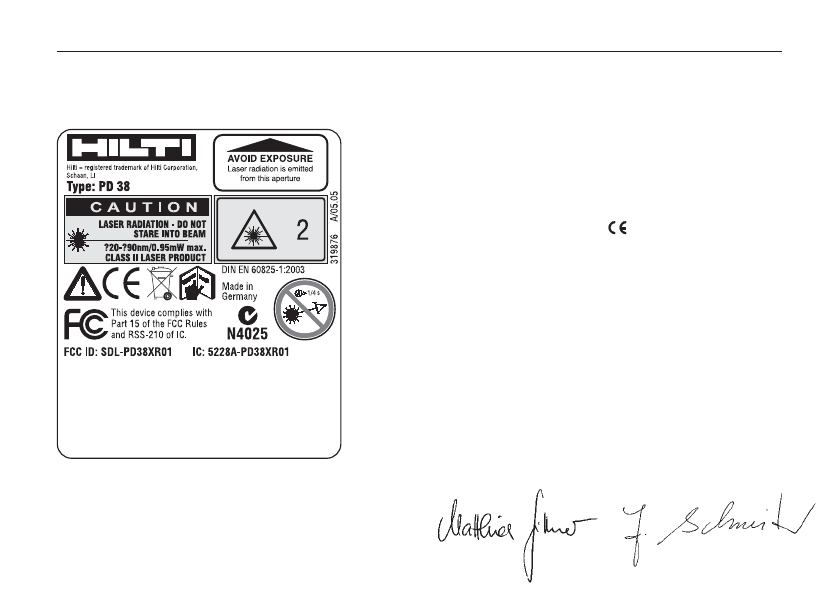
34
19. EC declaration of conformity
Designation: Laser range meter
Type: PD 38
Year of design: 2005
In conformance with
We declare, on our own responsibility, that
this product complies with the following
standards or directives: EN 301489-17;
EN 300328 and EN 60950-1; 2001 accord-
ing to the stipulations of the directive
89/336/EEC.
Hilti Corporation
Matthias Gillner
Head BU
Measuring Systems
11/ 2005
Dr. Heinz-Joachim
Schneider
Executive Vice President
BA Electric Tools &
Accessories
11/ 2005
19. EC declaration of conformity
Product information plate