Hilti PR3XR01 Rotating Laser User Manual Hilti Omega
Hilti Corporation Rotating Laser Hilti Omega
UserManual.wiki
>
Hilti
>
PR3XR01 User Manual
Users Manual
Navigation menu
Upload a User Manual
Namespaces
Wiki Guide
HTML
PDF
Info
Views
User Manual
Discussion / Help
Navigation

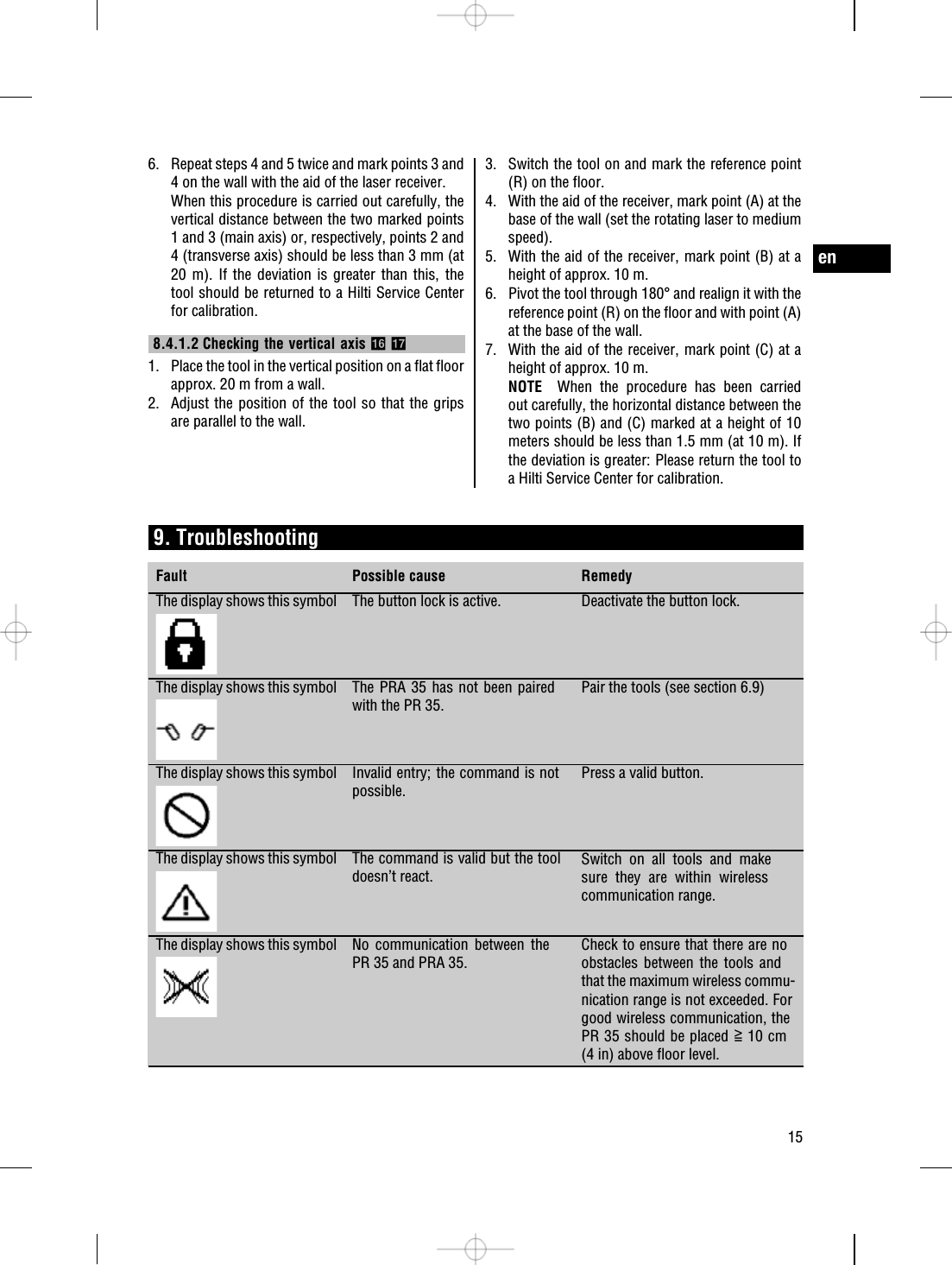
![180°20 m20 m15BAR10 m [30']20 m [60']16](https://usermanual.wiki/Hilti/PR3XR01/User-Guide-1325508-Page-6.png)
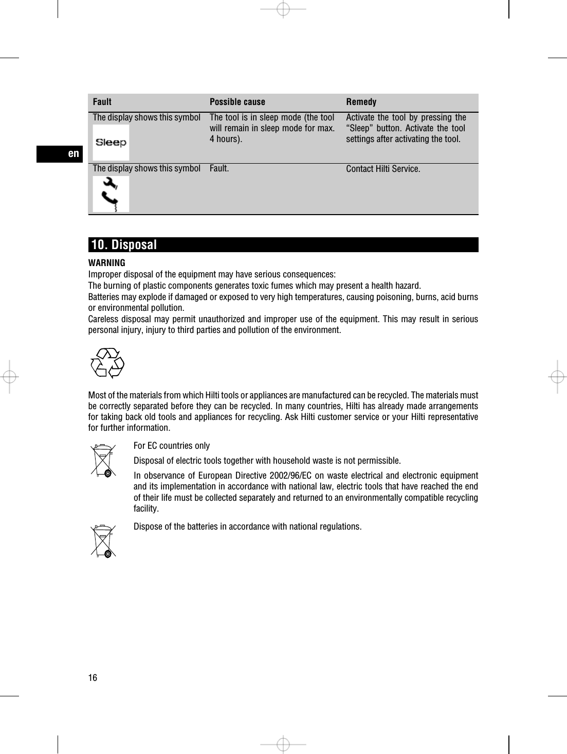
![BA1.5mm[1/16"]CR17](https://usermanual.wiki/Hilti/PR3XR01/User-Guide-1325508-Page-7.png)