Hilti PR3XR01 Rotating Laser User Manual Hilti Omega
Hilti Corporation Rotating Laser Hilti Omega
Hilti >
Users Manual

PR 35
Bedienungsanleitung de
Operating instructions en
Mode d’emploi fr
1
56
7
2
3
4
910
8
1
5
6
4
3
2
1
7
8
9
2
5
61
3
2
4
4
4
5
1
2
3
5
8
7
9
4
5
6 1
2
3
3
1
2
6
1
1
2
8 9
2
7
075
074
073
072
071
070
069
068
067
066
065
064
063
062
061
060
059
058
057
056
055
054
053
052
051
050
049
048
047
046
045
076
077
078
143
144
145
208
209
210
271
272
273
339
338
337
3
4
2
1
6
6
5
11
10
2
3
1
12
13
14
180
°
20 m20 m
15
B
A
R
10 m [30']
20 m [60']
16
B
A
1.5mm[1/16"]
C
R
17

*000000*
000000
Hilti Corporation
LI-9494 Schaan
Tel.:+423 / 2342111
Fax:+423 / 2342965
www.hilti.com
Hilti = registered trademark of Hilti Corp., Schaan W 0000 0310 00-Pos. 1 1 Printed in Liechtenstein © 2010
Right of technical and programme changes reserved S. E. & O. 000000 / A
ORIGINAL OPERATING INSTRUCTIONS
PR 35 rotating laser
It is essential that the operating instructions
are read before the tool is operated for the
first time.
Always keep these operating instructions
together with the tool.
Ensure that the operating instructions are
with the tool when it is given to other
persons.
Contents Page
1. General information 2
2. Description 2
3. Accessories 5
4. Technical data 5
5. Safety instructions 7
6. Before use 9
7. Operation 10
8. Care and maintenance 14
9. Troubleshooting 15
10. Disposal 16
11. Manufacturer’s warranty - tools 17
12. EC declaration of conformity 17
1These numbers refer to the corresponding illustra-
tions. The illustrations can be found on the fold-out
cover pages. Keep these pages open while studying
the operating instructions.
In these operating instructions, the designation “the
tool” or “the rotating laser” always refers to the
Hilti PR 35. The designation “remote control / laser
receiver” always refers to the Hilti PRA 35.
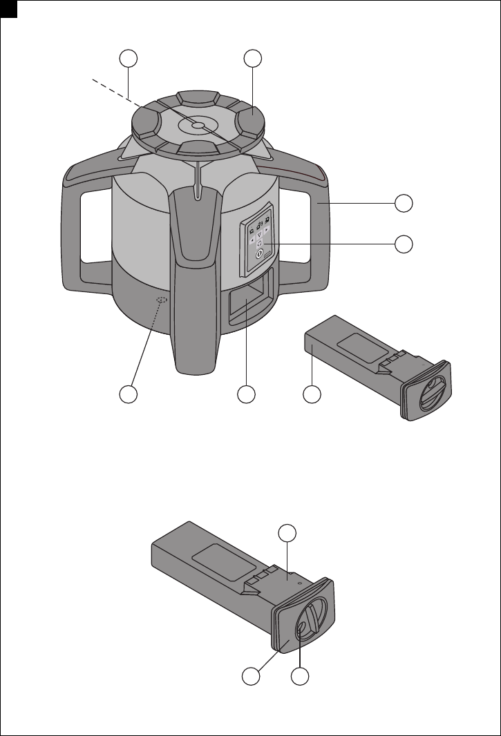
Rotating laser 1
@Laser beam (plane of rotation)
;Rotating head
=Grip
%Control panel
&Battery
(Battery compartment
)Base plate with 5/8" thread
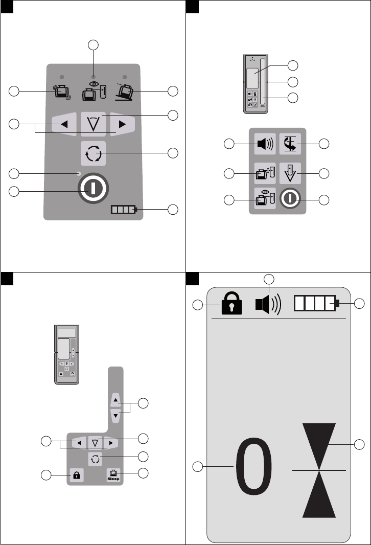
Rotating laser control panel 2
@On / off button
;Auto-leveling LED
=Direction buttons
%Shock warning deactivation LED
&Monitoring mode LED
(Slope LED
)Line function button
+Speed of rotation button
§Battery status
PRA 35 control panel (on the front of the receiver) 3
@On / off button
;Special line function
=Units button
%Volume button
&Automatic alignment button
(Monitoring mode button
)Receiving area
+Marking notch
§Display
PRA 35 control panel (on the rear of the remote
control) 4
@Sleep mode button
;Speed of rotation button
=Line function button
%Direction buttons (up/down)
&Direction buttons (left/right)
(Button lock
PRA 35 display 5
@Position of the receiver relative to the height of
the laser plane
;Battery status
=Signal tone volume
%Button lock
&Distance of receiver from laser plane
en
1
>1/4s
35
+LOWL WUDGHPDUNRIWKH+LOWL&RUSRUDWLRQ6FKDDQ/, 0DGHLQ*HUPDQ\
1PXFS
7OPN
N"
/$6(55$',$7,21'2127
67$5(,172%($0
QPP:PD[
&/$66,,/$6(5352'8&7
$"65*0/
(1
1. General information
1.1 Safety notices and their meaning
DANGER
Draws attention to imminent danger that could lead
to serious bodily injury or fatality.
WARNING
Draws attention to a potentially dangerous situation
that could lead to serious personal injury or fatality.
CAUTION
Draws attention to a potentially dangerous situation
that could lead to slight personal injury or damage to
the equipment or other property.
NOTE
Draws attention to an instruction or other useful
information.
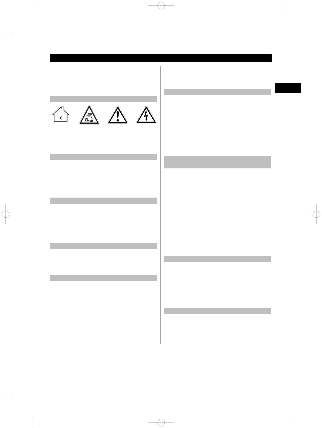
1.2 Explanation of the pictograms and other
information
Symbols
Read the
operating
instructions
before use.
General
warning
Return waste
material for
recycling.
Do not look
into the beam.
Symbol for Laser Class II / Class 2
Laser class II according
to CFR 21, § 1040 (FDA)
Laser class 2
according to
EN 60825:2008
Type identification plate
PR 35
Location of identification data on the tool
The type designation and serial number can be found
on the type identification plate on the tool. Make a
note of this data in your operating instructions and
always refer to it when making an enquiry to your
Hilti representative or service department.
Type:
Generation: 01
Serial no.:
2. Description
2.1 Use of the product as directed
The tool is designed to be used to determine, transfer and check levels, verticals, slopes and right angles.
Examples of its uses are: transferring datums and height marks, determining right angles for walls, vertical
alignment on reference points and setting out slopes.
Use of tools or AC adapters which show visible signs of damage is not permissible. Operation outdoors or in
damp conditions in “Charging during operation mode” is not permissible.
To avoid the risk of injury, use only genuine Hilti accessories and insert tools.
Observe the information printed in the operating instructions concerning operation, care and maintenance.
en
2

Take the influences of the surrounding area into account. Do not use the appliance where there is a risk of fire
or explosion.
Modification of the tool is not permissible.
2.2 PR 35 rotating laser
The Hilti PR 35 is a rotating laser tool with a visible rotating laser beam and a reference beam set at 90° to the
main beam. The PR 35 can be used for alignment in the vertical, horizontal and inclined planes.
2.3 Features
The tool makes it possible for a single person to level or align in any plane quickly and with great accuracy.
The tool features automatic leveling (within 10° (±5°)). The tool levels itself automatically after switching on.
The laser beam is emitted only when the specified accuracy has been achieved.
LEDs indicate the tool’s current operating status.
The tool is powered by a rechargeable Li‑ion battery which can be charged while the tool is in operation.
The PR 35 has a number of useful features: Monitoring mode, auto-alignment, sleep mode and button lock.
2.4 PRA 35 combined remote control and laser receiver
The PRA 35 is a combined remote control unit and laser receiver. It can be used to control the PR 35 rotating
laser over great distances. The PRA 35 also serves as a laser receiver and can thus be used to detect and
indicate the laser beam at great distances.
2.5 Digital distance measurement display
The PRA 35 shows the distance between the laser plane and the marking notch on the PRA 35 in the digital
display. This allows the user to determine the exact position of the receiver relative to the laser plane, with
millimeter accuracy, in a single operation.
2.6 Speed of rotation / line function
3 speeds of rotation are available for use (300, 600, 1200 /min). It is possible to switch between the individual
functions such as rotation and line functions. This is possible with the PR 35 rotating laser and with the PRA
35.
The line function improves laser beam visibility and limits the laser beam to a certain working area.
2.7 Automatic alignment and monitoring
Using the PR 35 and the PRA 35, a single person can align the laser plane automatically with a certain point
with great accuracy. When required, the laser plane can be checked at regular intervals with the aid of the
monitoring function and the PRA 35 in order to avoid possible deviations due to temperature fluctuations,
wind or similar.
2.8 Digital slope display with patented electronic axis alignment
The digital slope display can indicate a slope of up to 15%. This makes it possible to set out and check slopes
without having to make any calculations.
2.9 Shock warning
The tool goes into warning mode if it is knocked off level (due to vibration or impact) while in operation: all
LEDs blink and the laser switches off (the laser head no longer rotates).
en
3

2.10 Automatic cut-out
The laser does not switch on and all LEDs blink if the tool is set up outside its self-leveling range or movement
is blocked mechanically.
After switching the tool on, the shock warning only becomes active 1 minute after completion of leveling. If a
button is pressed within this time (before 1 minute has elapsed), the 1 minute delay before activation begins
again.
2.11 Items supplied
1 PR 35 rotating laser
1 PRA 35 remote control / laser receiver
1 PRA 80 receiver holder
1 PR 35 operating instructions
1 Target plate
1 Manufacturer’s certificate
1 PRA 84 Li‑ion battery
1 PRA 85 AC adapter
1 Hilti toolbox
2.12 Operating status indicators
Operating status is indicated as follows: auto-leveling LED, battery status LED, shock warning LED and slope
LED.
2.13 LED indicators
Auto-leveling LED
(green)
The green LED blinks. The tool is in the leveling phase.
The green LED lights
constantly.
The tool has leveled itself / is operating normally.
Shock warning LED
(orange)
The orange LED blinks. After switching on, the shock warning mode is not
immediately active (delay of approx. 1 minute).
The orange LED lights
constantly.
Shock warning mode is deactivated.
Monitoring LED (orange) The LED lights orange. The tool is in monitoring mode.
Slope LED (orange) The orange LED blinks. Alignment in the sloping plane.
The orange LED lights
constantly.
Slope mode is active.
Several LEDs light 2 LEDs blink orange. The tool is in axis alignment (slope) mode.
All LEDs All LEDs blink The tool has been bumped, knocked off level or is
exhibiting some other error.
2.14 Charge status of the Li‑ion battery during operation
LEDs light constantly LEDs blink Charge status C
LED 1,2,3,4 -C≧75 %
LED 1,2,3 -50 % ≦C < 75 %
LED 1,2 -25 % ≦C < 50 %
LED 1 -10 % ≦C < 25 %
-LED 1 C < 10 %
en
4

2.15 Charge status of the Li‑ion battery during charging while inserted in the tool
LEDs light constantly LEDs blink Charge status C
LED 1,2,3,4 -C = 75 %
LED 1,2,3 LED 4 C≧75%
LED 1,2 LED 3 50 % ≦C < 75 %
LED 1 LED 2 25 % ≦C < 50 %
-LED 1 C < 25 %
2.16 Charge status of the Li‑ion battery during charging while not inserted in the tool
If the red LED lights constantly, the battery is being charged.
If the red LED doesn’t light, the battery is fully charged.
3. Accessories
PRA 35 remote control / laser receiver
Laser receiver PRA 38, PRA 30/31
Target plate PRA 50/51
Wall mount PRA 70/71
Slope calculator PRA 52
Slope adapter PRA 78
Car charging connector PRA 86
Height transfer device PRA 81
AC adapter PRA 85
Battery PRA 84
Vertical angle PRA 770
Batter board receiver holder PRA 751
Batter board adapter PRA 750
Facade adapter PRA 760
Various tripods PUA 20, PUA 30, PA 921, PA 931/2
Telescopic staffs PA 960, PUA 50, PUA 55/56
4. Technical data
Right of technical changes reserved.
PR 35
PR 35 receiving range (diameter) Typical distance with PRA 35: 2…300 m (6...900 ft)
Range of remote control (circle diameter) Typical distance with PRA 35: 0…100 m (0...300 ft)
Accuracy 0.75 mm per 10 m horizontal distance
(77° F, ¹/₁₁" in 100 ft) at a temperature of 25°C
Plumb beam Continuous, perpendicular to the plane of rotation
PR 35 laser class Class 2, visible, 620-690 nm / Po < 4.85 min, ≧
300 /min (EN 60825-1:2008 / IEC 825 - 1:2008);
class II (CFR 21 § 1040 (FDA))
en
5

Speed of rotation 300, 600, >1200 /min
Slope range 15% (8.6°)
Self-leveling range x=13.6° (+5°, -8.6°); y=10° (±5°)
Power source 7.2V/ 4.5 Ah Li‑ion battery
Battery life Temperature +20°C (+68°F), Li‑ion battery: ≥30 h
Operating temperature range -20…+50°C (-4°F to 122°F)
Storage temperature range (dry) -25…+60°C (-13°F to 140°F)
Protection class As perIP 56 (in accordance withIEC 529)
Tripod thread ⁵⁄₈"X11
Weight (incl. PRA 84) 2.4 kg (5.3 lbs)
Dimensions (L x W x H) 252 mm X 252 mm X 209 mm (10" x 10" x 8")
PRA 35
Detection range (area diameter) 2…300 m (6 to 1000 ft)
Signal tone generator 3 volume levels plus mute setting
Liquid crystal display On both sides
Indicator range, distance from zero ±50mm(±2in)
Laser plane indication accuracy ± 0.5 mm (± 0.02 in)
Width of receiving area 120 mm (5 in)
Center indication from top edge of casing 75 mm (3 in)
Marking notches On both sides
Automatic power-off When no beam is detected: 15 min
Dimensions 160 mm X 67 mm X 24 mm
Weight (including batteries) 0.25 kg (0.6 lbs)
Power source 2 AA batteries
Battery life (alkaline-manganese) Temperature +20°C (+68°F): 40 h
Operating temperature range -20…+50°C (-4 °F to 122 °F)
Storage temperature range -25…+60°C (-13 °F to 140 °F)
Protection class IP 56
in accordance with IEC 529
PRA 84 Li‑ion battery
Rated voltage (normal mode) 7.2 V
Maximum voltage (during operation or during
charging while in operation)
13 V
Rated current 160 mAh
Charging time 130 min, at 25 C
Operating temperature range -20…+50°C (-4°F to 122°F)
Storage temperature range (dry) -25…+60°C (-13°F to 140°F)
Charging temperature range (also for charging
during operation)
+0…+40°C (32° to +104°F)
Weight 0.3 kg (0.67 lbs)
Dimensions (L x W x H) 160 mm X 45 mm X 36 mm (6.3" x 1.8" x 1.4")
PRA 85 AC adapter
AC supply 115…230 V
AC frequency 47…63 Hz
en
6
Rated power 40 W
Rated voltage 12 V
Operating temperature range +0…+40°C (32°F to +104°F)
Storage temperature range (dry) -25…+60°C (-13°F to 140°F)
Weight 0.23 kg (0.51 lbs)
Dimensions (L x W x H) 110 mm X 50 mm X 32 mm (4.3" x 2" x 1.3")
5. Safety instructions
5.1 Basic information concerning safety
In addition to the information relevant to safety
given in each of the sections of these operating
instructions, the following points must be strictly
observed at all times.
5.2 General safety rules
a) Do not render safety devices ineffective and do
not remove information and warning notices.
b) Keep laser tools out of reach of children.
c) Failure to follow the correct procedures when
opening the tool may cause emission of laser
radiation in excess of class 2. Have the tool
repaired only at a Hilti Service Center.
d) Take the influences of the surrounding area into
account. Do not use the tool where there is a risk
of fire or explosion.
e) (Statement in accordance with FCC §15.21):
Changes or modifications not expressly approved
by the manufacturer can void the user’s authority
to operate the equipment.
5.3 Proper organization of the work area
a) Secure the area in which you are working and
take care to avoid directing the beam towards
other persons or towards yourself when setting
up the tool.
b) Avoid unfavorable body positions when working
from ladders. Make sure you work from a safe
stance and stay in balance at all times.
c) Measurements taken through panes of glass or
other objects may be inaccurate.
d) Ensure that the tool is set up on a steady, level
surface (not subject to vibration).
e) Use the tool only within its specified limits.
f) Check that your PR 35 is responding only to your
PRA 35 and not to other PRA 35s that may be in
use on the jobsite.
5.3.1 Electromagnetic compatibility
Although the tool complies with the strict require-
ments of the applicable directives, Hilti cannot en-
tirely rule out the possibility of the tool being subject
to interference caused by powerful electromagnetic
radiation, leading to incorrect operation. Check the
accuracy of the tool by taking measurements by other
means when working under such conditions or if you
are unsure. Likewise, Hilti cannot rule out the pos-
sibility of interference with other devices (e.g. aircraft
navigation equipment).
5.3.2 Laser classification for laser class II
appliances
The tool complies with Laser Class 2 in accordance
with IEC825-1:2008 / EN60825-1:2008 and Class
II in accordance with CFR 21 § 1040 (FDA). This
tool may be used without need for further protective
measures. The eyelid closure reflex protects the eyes
when a person looks into the beam unintentionally for
a brief moment. This eyelid closure reflex, however,
may be negatively affected by medicines, alcohol or
drugs. Nevertheless, as with the sun, one should not
look directly into sources of bright light. Do not direct
the laser beam toward persons.
5.4 General safety rules
a) Check the condition of the tool before use. If the
tool is found to be damaged, have it repaired at
a Hilti service center.
b) The user must check the accuracy of the tool
after it has been dropped or subjected to other
mechanical stresses.
en
7

c) When the tool is brought into a warm environ-
ment from very cold conditions, or vice-versa,
allow it to become acclimatized before use.
d) If mounting on an adapter, check that the tool is
screwed on securely.
e) Keep the laser exit aperture clean to avoid meas-
urement errors.
f) Although the tool is designed for the tough con-
ditions of jobsite use, as with other optical and
electronic instruments (e.g. binoculars, spec-
tacles, cameras) it should be treated with care.
g) Although the tool is protected to prevent entry
of dampness, it should be wiped dry each time
before being put away in its transport container.
h) Check the tool before using it for important meas-
uring work.
i) Check the accuracy of the measurements several
times during use of the tool.
j) Use the AC adapter only for connecting to the AC
supply.
k) Check to ensure that the tool and AC adapter do
not present an obstacle that could lead to a risk
of tripping and personal injury.
l) Ensure that the workplace is well lit.
m)Avoid body contact with earthed or grounded
surfaces, such as pipes, radiators, ranges and
refrigerators. There is an increased risk of electric
shock if your body is earthed or grounded.
n) Check the condition of the extension cord and
replace it if damage is found. Do not touch the
AC adapter if the extension cord or AC adapter are
damaged while working. Disconnect the supply
cord plug from the power outlet. Damaged supply
cords or extension cords present a risk of electric
shock.
o) Do not expose the supply cord to heat, oil or
sharp edges.
p) Never operate the AC adapter when it is dirty
or wet. Dust (especially dust from conductive
materials) or dampness adhering to the surface
of the AC adapter may, under unfavorable condi-
tions, lead to electric shock. Dirty or dusty tools
should thus be checked at a Hilti Service Center
at regular intervals, especially if used frequently
for working on conductive materials.
q) Avoid touching the contacts.
5.4.1 Battery tool use and care
a) Check that the tool is switched off before fitting
the battery. Use only the Hilti battery approved for
use with this tool.
b) Do not expose batteries to high temperatures or
fire. This presents a risk of explosion.
c) Do not disassemble, squash or incinerate batter-
ies and do not subject them to temperatures over
75°C. A risk of fire, explosion or injury through
contact with caustic substances may otherwise
result.
d) Avoid ingress of moisture. Moisture may cause
a short circuit resulting in a risk of burning injury
or fire.
e) Do not use batteries other than those approved
for use with the applicable tool or appliance.
Use of other batteries or use of the battery for
purposes for which it is not intended presents a
risk of fire and explosion.
f) Observe the special instructions applicable to the
transport, storage and use of Li-ion batteries.
g) Avoid short-circuiting the battery. Before insert-
ing the battery in the tool, check that the terminals
of the battery and the tool are free from for-
eign objects. Short-circuiting the battery terminals
presents a risk of fire, explosion or contact with
caustic substances.
h) Do not charge or continue to use damaged bat-
teries (e.g. batteries with cracks, broken parts,
bent or pushed-in and/or pulled-out contacts).
i) Use only the specified battery to power the tool
and use only the PRA 85 AC adapter or PRA 86
car charging connector for charging. Failure to
observe these points may result in damage to the
tool.
en
8
6. Before use
NOTE
The PR 35 may be powered only by the Hilti PRA 84
battery, which is manufactured in accordance with
IEC 60285.
6.1 Charging the battery
DANGER
Use only the Hilti battery, car charging connector
and Hilti AC adapter listed under “Accessories”.
6.1.1 Charging a new battery for the first time
Charge the battery fully before using it for the first
time.
NOTE
Make sure the system to be charged is standing
securely.
6.1.2 Charging a previously used battery
Ensure that the outer surfaces of the battery are clean
and dry before inserting it in the tool.
Li-ion batteries are ready for use at any time, even
when only partly charged. During charging, progress
is indicated by the LEDs on the tool.
6.2 Options for charging the battery
DANGER
The PRA 85 AC adapter is for indoor use only. Avoid
ingress of moisture.
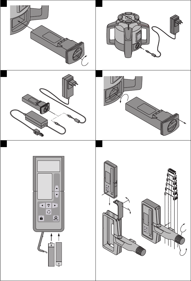
6.2.1 Charging the battery in the tool 67
NOTE
When charging, check that the temperature is within
the recommended charging temperature range (0 to
40°C/ 32 to 104°F).
1. Insert the battery in the battery compartment.
2. Swing the cover to the side so that the charging
cord socket becomes accessible.
3. Connect the charging cord from the AC adapter
or car charging connector to the battery.
4. During charging, the charge status is indicated by
the battery status LEDs on the tool (the tool must
be switched on).
6.2.2 Charging the battery outside the tool 8
NOTE
When charging, check that the temperature is within
the recommended charging temperature range (0 to
40°C/ 32 to 104°F).
1. Remove the battery from the tool and connect it
to the AC adapter or car charging connector.
2. The red LED on the battery lights while charging
is in progress.
6.2.3 Charging the battery while the tool is in
operation 8
CAUTION
Avoid ingress of moisture. Moisture may cause a
short circuit resulting in a risk of burning injury or
fire.
1. Swing the cover to the side so that the charging
cord socket becomes accessible.
2. Connect the charging cord from the AC adapter
to the battery.
3. The tool continues to operate while charging is in
progress.
4. During charging, the charging status is indicated
by the LEDs on the tool.
6.3 Battery use and care
Store the battery in a cool, dry place. Never store
the battery where it is exposed to direct sunlight or
sources of heat, e.g. on heaters / radiators or behind a
motor vehicle windscreen. Batteries that have reached
the end of their life must be disposed of safely and
correctly to avoid environmental pollution.
6.4 Fitting the battery 6
CAUTION
Before inserting the battery in the tool, check that
the terminals of the battery and the tool are free
from foreign objects.
en
9

1. Push the battery into the tool.
2. Turn the catch in a clockwise direction to the
second detent (the “locked” symbol is displayed).
6.5 Removing the battery 9
1. Turn the catch in a counterclockwise direction
from the second detent back to the “open” posi-
tion (the “unlocked” symbol is displayed).
2. Pull the battery out of the tool.
6.6 Switching the tool on
Press the “On / off” button.
NOTE
After switching on, the tool begins the automatic lev-
eling process (takes max. 40 seconds). After comple-
tion of the leveling process, the laser beam switches
on and begins to rotate in the normal direction. When
leveling in the horizontal plane the laser head rotates
automatically at medium speed and, when working
in the vertical plane, a reference point is projected
downwards.
6.7 LED indicators
Please refer to section 2 “Description”.
6.8 Inserting batteries in the PRA 35
CAUTION
Do not use damaged batteries.
DANGER
Do not mix old and new batteries. Do not mix batteries
of different makes or types.
NOTE
The PRA 35 may be powered only by batteries man-
ufactured in accordance with the applicable interna-
tional standards.
6.9 Pairing
NOTE
In the state supplied, the PR 35 rotating laser and the
PRA 35 remote control / laser receiver have not been
paired. They cannot operate together until they have
been paired.
The PR 35 rotating laser and the PRA 35 must be set
to operate as a pair before they can be used together.
Pairing the tools means that they are configured to
communicate with each other. The PR 35 rotating
laser then receives signals only from the PRA 35 with
which it has been paired. Pairing makes it possible to
work alongside other rotating lasers without risk of
settings being altered inadvertently by these tools.
1. Press the “On / off” buttons on the PR 35 rotating
laser and on the PRA 35 simultaneously (or on
the PRA 90 if this tool is being used) and keep
the buttons pressed for at least 3 seconds.
When pairing has been carried out successfully, a
signal tone is emitted by the PRA 35 and all LEDs
on the PR 35 rotating laser blink.
2. Switch off the tools that have been paired and
then switch them on again.
The “Paired” symbol appears in the display (see
“Troubleshooting” section).
7. Operation
7.1 Switching the tool on
Press the “On / off” button.
NOTE
After switching on, the tool begins to level itself
automatically.
7.2 Working with the PRA 35
The PRA 35 is a laser receiver (front) and, at the
same time, a remote control unit (rear). The remote
control makes working with the rotating laser more
convenient and is required in order to make use of
certain functions.
en
10

7.2.1 Working with the laser receiver as a hand-
held unit
1. Press the “On / off” button.
2. Hold the PRA 35 in the plane of the rotating laser
beam.
The laser beam is indicated by visual and audible
signals.
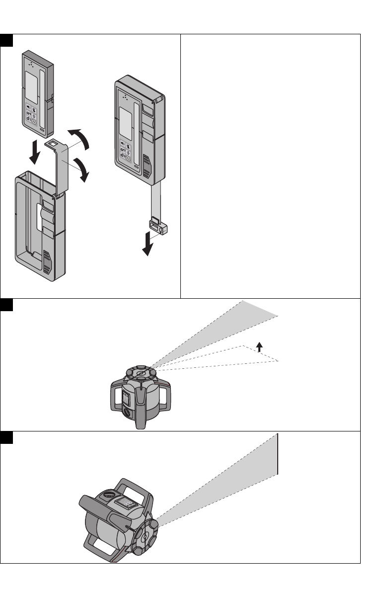
7.2.2 Using the PRA 35 in the PRA 80 receiver
holder
1. Open the catch on the PRA 80.
2. Place the PRA 35 in the PRA 80 receiver holder.
3. Close the catch on the PRA 80.
4. Switch the laser receiver on by pressing the “On
/ off” button.
5. Turn the rotating grip to the open position.
6. Fit the PRA 80 receiver holder onto the telescopic
staff or leveling staff and secure it by tightening
the rotating grip.
7. Hold the PRA 35 with the receiving window in the
plane of the rotating laser beam.
The laser beam is indicated by visual and audible
signals.
7.2.3 Working with the PRA 81 height transfer
device
1. Open the catch on the PRA 81.
2. Insert the PRA 35 laser receiver in the PRA 81
height transfer device.
3. Close the catch on the PRA 81.
4. Switch the PRA 35 on by pressing the “On / off”
button.
5. Position the PRA 35 so that the distance display
shows “0”.
6. Hold the PRA 35 with the receiving window in the
plane of the rotating laser beam.
7. Use the measuring tape to measure the desired
distance.
7.2.4 Menu options
Press the “On / off” button for 2 seconds when
switching the PRA 35 on.
The menu then appears in the display.
Use the measuring units button to select metric or
imperial measuring units.
Use the volume button to assign the more rapid
signal tone to the upper or lower area of the receiving
window.
To save the settings, switch the PRA 35 off.
7.2.5 Setting the measuring unit
The “units” button can be used to set the desired
measuring unit according to the country of use (mm
/ cm / off) or (¹⁄₈in / ¹⁄₁₆in / off).
7.2.6 Setting the volume of the signal tone
The tool is set to “Normal” volume when switched on.
The volume can be adjusted by pressing the “Signal
tone” button. One of the following settings can be
selected: “Low”, “Normal”, “High” or “Off”.
7.2.7 Button lock and confirmation of entries
The button lock function of the PRA 35 prevents
unintentional entries being made and is indicated at
the upper left edge of the display on both sides of the
PRA 35. The lock symbol is either open (unlocked) or
closed (locked). During operation, the command must
be confirmed by pressing the button again in order
to rule out incorrect manipulation. This requirement
for confirmation is indicated in the display but, for
the sake of simplicity, is not mentioned each time in
other sections of the operating instructions.
7.3 Basic functions of the PR 35
The basic functions are horizontal and vertical align-
ment plus working with slopes.
7.3.1 Setting the speed of rotation
NOTE
The speed of rotation can be adjusted by pressing the
“Speed of rotation” button (on the control panel of
the rotating laser or on the PRA 35). The speeds of
rotation are: 300, 600 and >1200 /min. The receiver
works best at 600 /min and should not be used at
speeds of >1200 /min.
7.3.2 Selecting the line function
NOTE
When the “Line” button is pressed, the rotating laser
projects a line which can be lengthened or shortened
by further presses of the button.
NOTE
With the aid of the PRA 35 laser receiver it is also
possible to stop rotation of the laser and to project a
line at the position of the PRA 35. To do this, move
the PRA 35 laser receiver into the plane of the laser
beam and press the “Special line button”.
en
11

7.3.3 Moving the laser line
The laser line can be moved to the left or right by
pressing the “Direction” buttons (PR 35 or PRA 35).
Holding down the button results in continuous move-
ment and increases the speed of movement of the
laser line.
7.4 Working in the horizontal plane
7.4.1 Setting up
1. Set up the tool in a suitable position for the
application, e.g. on a tripod. The angle of the
surface on which it is stood should not exceed
10° (± 5°).
2. Press the “On / off” button.
3. The laser beam switches on and the head begins
to rotate at a speed of 300 /min as soon as the
tool has leveled itself.
7.5 Working in the vertical plane
1. When working in the vertical plane, place the
tool on its metal feet so that the control panel
faces upwards. Alternatively, the rotating laser
may also be mounted on a suitable tripod, wall
bracket, facade adapter or batter board adapter.
2. Adjust the tool so that its vertical axis is positioned
in the required direction.
3. In order to ensure that the tool’s specified accur-
acy can be maintained, make sure that it is set up
on a level surface or mounted sufficiently level on
the tripod or other accessory.
4. Press the “On / off” button.
After the tool has leveled itself automatically, it
projects a stationary laser beam vertically down-
wards. This projected point is the reference point
and is used to position the tool.
7.5.1 Manual alignment
Manual alignment of the vertical plane is carried out
by pressing the “Up” or “Down” buttons on the rear
of the PRA 35.
7.5.2 Auto-alignment
Hold the PRA 35 at the point to be aligned, with the
receiving side facing the PR 35, and then press the
“Automatic alignment” button.
The laser plane alignment procedure then begins. A
constant signal tone is emitted while this is taking
place.
The search can be adjusted by pressing the “Direc-
tion” buttons.
As soon as the laser beam strikes the receiving area
of the PRA 35, the beam moves to the position of the
marking notch (reference plane).
A short signal tone is emitted, indicating the end of
the procedure, as soon as the laser beam finds the
position of the marking notch.
7.6 Working with slopes
NOTE
For optimum results, check that the PR 35 is correctly
aligned. This is best done by selecting 2 points each
5 m to the left and right of the tool but parallel to the
tool axis. Mark the height of the horizontal plane and
then, after setting the slope, mark the heights. The
tool is aligned optimally only when these heights are
identical at both points.
7.6.1 Setting up
NOTE
The slope can be set manually, automatically, or by
using the PRA 76/78 slope adapter.
1. Set up the tool in a suitable position for the
application, e.g. on a tripod.
2. With the aid of the target notch on the head of
the PR 35, bring the tool parallel to the inclined
plane.
3. Press the “On / off” button for at least 8 seconds
until the orange LED lights.
4. The laser beam switches on as soon as the tool
has leveled itself. The PRA 35 can then be set to
the desired slope.
7.6.2 Setting the slope manually
Press the “Up” and “Down” arrow buttons on the
PRA 35 remote control. Pressing the arrow buttons
for longer causes the values to change more quickly.
The LED display on the PRA 35 shows the angle of
slope.
If no button is pressed for 3 seconds, the tool will be
set to the most recently displayed value.
7.6.3 Setting the slope automatically
NOTE
The slope can be set automatically only when slope
mode is active and when a PRA 35 laser receiver is
used.
en
12

Incline the laser as described at 7.5.2, but in alignment
with the inclined plane.
7.6.4 Optional electronic alignment
After setting the slope as described above, alignment
of the PR 35 can be optimized by Hilti’s patented
electronic alignment system.
1. Position the PRA 35 centrally opposite the PR 35
at the end of the inclined plane. It can be held
still by hand or fixed in place with the aid of the
PRA 80.
2. Switch the PRA 35 on.
3. Activate electronic alignment on the PR 35 by
pressing the “Left” arrow button.
4. If the shock warning / slope LEDs blink, the
PRA 35 is not receiving the laser beam from the
PR 35.
5. If the shock warning / monitoring LEDs blink,
realign the PR 35 by moving it counterclockwise.
6. If the slope / monitoring LEDs blink, realign the
PR 35 by moving it clockwise.
7. If the monitoring LED blinks, alignment is correct.
8. End electronic alignment mode by pressing the
“Right” arrow button.
7.6.5 Setting the slope with the aid of the
PRA 76/78 slope adapter
NOTE
Check that the slope adapter is fitted correctly between
the tripod and the tool (please refer to the operating
instructions).
7.7 Monitoring
The monitoring function checks at regular intervals
whether the plane that is set (vertical, horizontal
or inclined) has been altered inadvertently (e.g. by
vibration). If this is the case, the projected plane
will be realigned to the zero point (i.e. the marking
notch on the PRA 35) (so long as it is still within the
receiving area). A PRA 35 is required for use of the
monitoring function. An additional laser receiver can
be used to detect the laser beam while the laser beam
is being monitored.
1. Preparation for activation of the monitoring func-
tion is basically the same as the procedure for
activation of automatic alignment mode.
2. Position the tool at the desired starting point 1
and switch it on.
3. Position PRA 35 laser receiver at the reference
point (point 2) on the axis and secure it there.
The PRA 751 can be used to secure it. The tool
(point 1) and the PRA 35 (point 2) then form
anchor points on the plane. Take care to ensure
that the marking notch on the PRA 35 is at exactly
the height at which the rotating laser is later
to project the laser line or point. The red laser
receiving surface on the PRA 35 must face the
rotating laser.
4. Take care to ensure there are no obstructions
between the rotating laser and the PRA 35 laser re-
ceiver which could interfere with communication
between the devices. Glass and other translucent
materials may also interfere with communication
between the devices. Reflections from windows
may also cause interference.
5. Switch the PR 35 and the PRA 35 on. The mon-
itoring function can be activated by pressing the
“Monitoring mode” button on the PRA 35.
6. The system is then in monitoring mode. The
function is indicated in the display on the PRA 35
by two regularly blinking arrows pointing toward
the axis in which alignment is to be carried out.
7. The monitoring system checks at regular intervals
whether the laser plane has shifted. If it is found
to have shifted, the laser plane will be readjusted
to the original marking plane as far as possible.
If the marking plane is outside the self-levelling
range (10° (±5°)) or the line of sight between the
rotating laser and the laser receiver is blocked
for a certain length of time, an error message is
displayed.
7.8 Returning to standard mode
In order to return to standard mode, horizontal align-
ment, 300 /min, the tool must be switched off and
restarted.
7.9 Sleep mode
The PR 35 saves power when in sleep mode. The
laser is switched off, thereby extending battery life.
Activate sleep mode by pressing the “Sleep mode”
button on the PRA 35.
Deactivate sleep mode by pressing the “Sleep mode”
button on the PRA 35 again.
After reactivating the PR 35, check the laser settings
in order to ensure accuracy.
en
13

7.10 Working with the target plate
The target plate improves laser beam visibility. The
target plate should be used in bright conditions or
whenever improved laser beam visibility is desired.
Simply bring the target plate into the plane of the
projected laser beam. The target plate is made from
a material that makes the laser beam more easily
visible.
8. Care and maintenance
8.1 Cleaning and drying
1. Blow dust off the lenses.
2. Do not touch the glass with the fingers.
3. Use only a clean, soft cloth for cleaning. If neces-
sary, moisten the cloth slightly with pure alcohol
or a little water.
NOTE Abrasive cleaning materials may scratch
the glass and impair the accuracy of the laser tool.
NOTE Do not use any other liquids as these may
damage the plastic components.
4. Observe the temperature limits when storing your
equipment. This is particularly important in winter
/ summer if the equipment is kept inside a motor
vehicle (-30°C to +60°C).
8.2 Storage
Remove the tool from its case if it has become wet.
The tool, its carrying case and accessories should
be cleaned and dried (at maximum 40°C / 104°F).
Repack the equipment only once it is completely dry.
Check the accuracy of the equipment before it is used
after a long period of storage or transportation.
Remove the batteries from the tool before storing it
for a long period. Leaking batteries may damage the
tool.
Store the tool in the Hilti toolbox in a dry place.
8.3 Transport
Use the Hilti toolbox or packaging of equivalent quality
for transporting or shipping your equipment.
CAUTION
Always remove the batteries before shipping the
tool.
8.4 Hilti Calibration Service
We recommend that the tool is checked by the Hilti
Calibration Service at regular intervals in order to
verify its reliability in accordance with standards and
legal requirements.
Use can be made of the Hilti Calibration Service
at any time, but checking at least once a year is
recommended.
The Calibration Service provides confirmation that the
tool is in conformance, on the day it is tested, with
the specifications given in the operating instructions.
The tool will be readjusted if deviations from the
manufacturer’s specification are found. After check-
ing and adjustment, a calibration sticker applied to
the tool and a calibration certificate provide written
verification that the tool operates in accordance with
the manufacturer’s specification.
Calibration certificates are always required by com-
panies certified according to ISO 900x.
Your local Hilti Center or representative will be pleased
to provide further information.
8.4.1 Checking accuracy
In order to ensure compliance with the technical
specifications, the tool should be checked regularly
(at least before each major / relevant job).
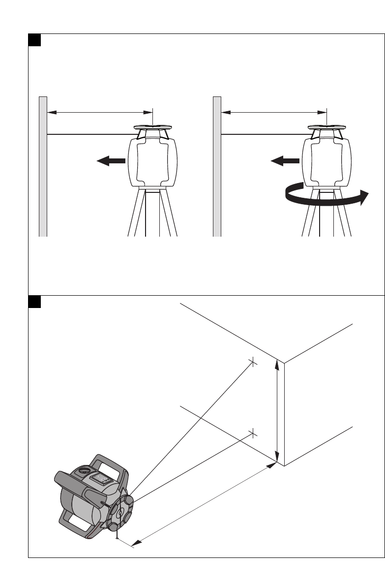
8.4.1.1 Checking the main and transverse
horizontal axes
1. Set up the tripod approx. 20 m from a wall and
level the tripod head with a spirit level.
2. Mount the tool on the tripod and use the aiming
notch to aim the tool at the wall.
3. Use the receiver to catch the laser beam and mark
a point (point 1) on the wall.
4. Pivot the tool clockwise through 90° about its
own axis. In doing so, ensure that the height of
the tool does not change.
5. Use the laser receiver to catch the laser beam and
mark a second point (point 2) on the wall.
en
14
6. Repeat steps 4 and 5 twice and mark points 3 and
4 on the wall with the aid of the laser receiver.
When this procedure is carried out carefully, the
vertical distance between the two marked points
1 and 3 (main axis) or, respectively, points 2 and
4 (transverse axis) should be less than 3 mm (at
20 m). If the deviation is greater than this, the
tool should be returned to a Hilti Service Center
for calibration.
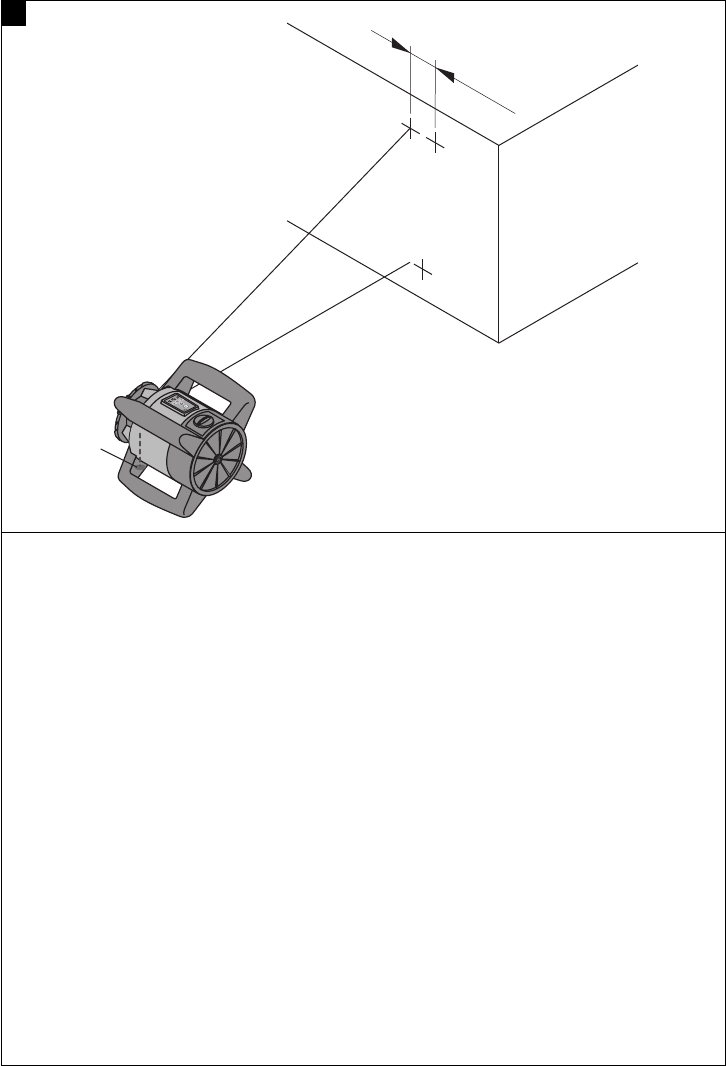
8.4.1.2 Checking the vertical axis
1. Place the tool in the vertical position on a flat floor
approx. 20 m from a wall.
2. Adjust the position of the tool so that the grips
are parallel to the wall.
3. Switch the tool on and mark the reference point
(R) on the floor.
4. With the aid of the receiver, mark point (A) at the
base of the wall (set the rotating laser to medium
speed).
5. With the aid of the receiver, mark point (B) at a
height of approx. 10 m.
6. Pivot the tool through 180° and realign it with the
reference point (R) on the floor and with point (A)
at the base of the wall.
7. With the aid of the receiver, mark point (C) at a
height of approx. 10 m.
NOTE When the procedure has been carried
out carefully, the horizontal distance between the
two points (B) and (C) marked at a height of 10
meters should be less than 1.5 mm (at 10 m). If
the deviation is greater: Please return the tool to
a Hilti Service Center for calibration.
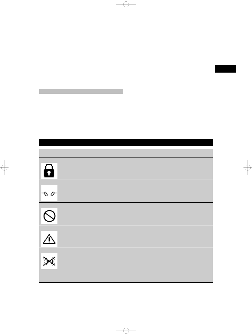
9. Troubleshooting
Fault Possible cause Remedy
The display shows this symbol The button lock is active. Deactivate the button lock.
The display shows this symbol The PRA 35 has not been paired
with the PR 35.
Pair the tools (see section 6.9)
The display shows this symbol Invalid entry; the command is not
possible.
Press a valid button.
The display shows this symbol The command is valid but the tool
doesn’t react.
Switch on all tools and make
sure they are within wireless
communication range.
The display shows this symbol No communication between the
PR 35 and PRA 35.
Check to ensure that there are no
obstacles between the tools and
that the maximum wireless commu-
nication range is not exceeded. For
good wireless communication, the
PR 35 should be placed ≧10 cm
(4 in) above floor level.
en
15
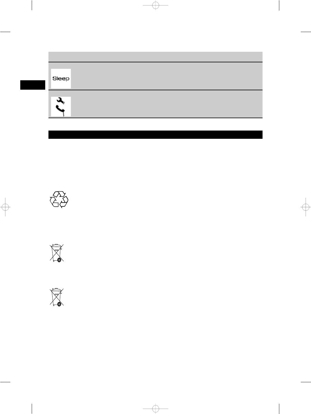
Fault Possible cause Remedy
The display shows this symbol The tool is in sleep mode (the tool
will remain in sleep mode for max.
4 hours).
Activate the tool by pressing the
“Sleep” button. Activate the tool
settings after activating the tool.
The display shows this symbol Fault. Contact Hilti Service.
10. Disposal
WARNING
Improper disposal of the equipment may have serious consequences:
The burning of plastic components generates toxic fumes which may present a health hazard.
Batteries may explode if damaged or exposed to very high temperatures, causing poisoning, burns, acid burns
or environmental pollution.
Careless disposal may permit unauthorized and improper use of the equipment. This may result in serious
personal injury, injury to third parties and pollution of the environment.
Most of the materials from which Hilti tools or appliances are manufactured can be recycled. The materials must
be correctly separated before they can be recycled. In many countries, Hilti has already made arrangements
for taking back old tools and appliances for recycling. Ask Hilti customer service or your Hilti representative
for further information.
For EC countries only
Disposal of electric tools together with household waste is not permissible.
In observance of European Directive 2002/96/EC on waste electrical and electronic equipment
and its implementation in accordance with national law, electric tools that have reached the end
of their life must be collected separately and returned to an environmentally compatible recycling
facility.
Dispose of the batteries in accordance with national regulations.
en
16
11. Manufacturer’s warranty - tools
Hilti warrants that the tool supplied is free of defects
in material and workmanship. This warranty is valid
so long as the tool is operated and handled correctly,
cleaned and serviced properly and in accordance with
the Hilti Operating Instructions, and the technical
system is maintained. This means that only original
Hilti consumables, components and spare parts may
be used in the tool.
This warranty provides the free-of-charge repair or
replacement of defective parts only over the entire
lifespan of the tool. Parts requiring repair or replace-
ment as a result of normal wear and tear are not
covered by this warranty.
Additional claims are excluded, unless stringent na-
tional rules prohibit such exclusion. In particular,
Hilti is not obligated for direct, indirect, incidental
or consequential damages, losses or expenses in
connection with, or by reason of, the use of, or
inability to use the tool for any purpose. Implied
warranties of merchantability or fitness for a par-
ticular purpose are specifically excluded.
For repair or replacement, send the tool or related
parts immediately upon discovery of the defect to
the address of the local Hilti marketing organization
provided.
This constitutes Hilti’s entire obligation with regard
to warranty and supersedes all prior or contempor-
aneous comments and oral or written agreements
concerning warranties.
12. EC declaration of conformity
Designation: Rotating laser
Type: PR 35
Year of design: 2010
We declare, on our sole responsibility, that this
product complies with the following directives and
standards: EN 300 440‑2, EN 301 489‑3 V1.4.1,
EN 60950‑1, EN 55014‑1, EN 55014‑2, EN 61000‑3‑2,
EN 61000‑3‑3, 2004/108/EC, 2006/42/EC.
Hilti Corporation
Dietmar Sartor Tassilo Deinzer
Head of BA Quality and Process
Management
Head BU Measuring Systems
Business Area Electric Tools & Ac-
cessories
BU Measuring Systems
04 2010 04 2010
en
17