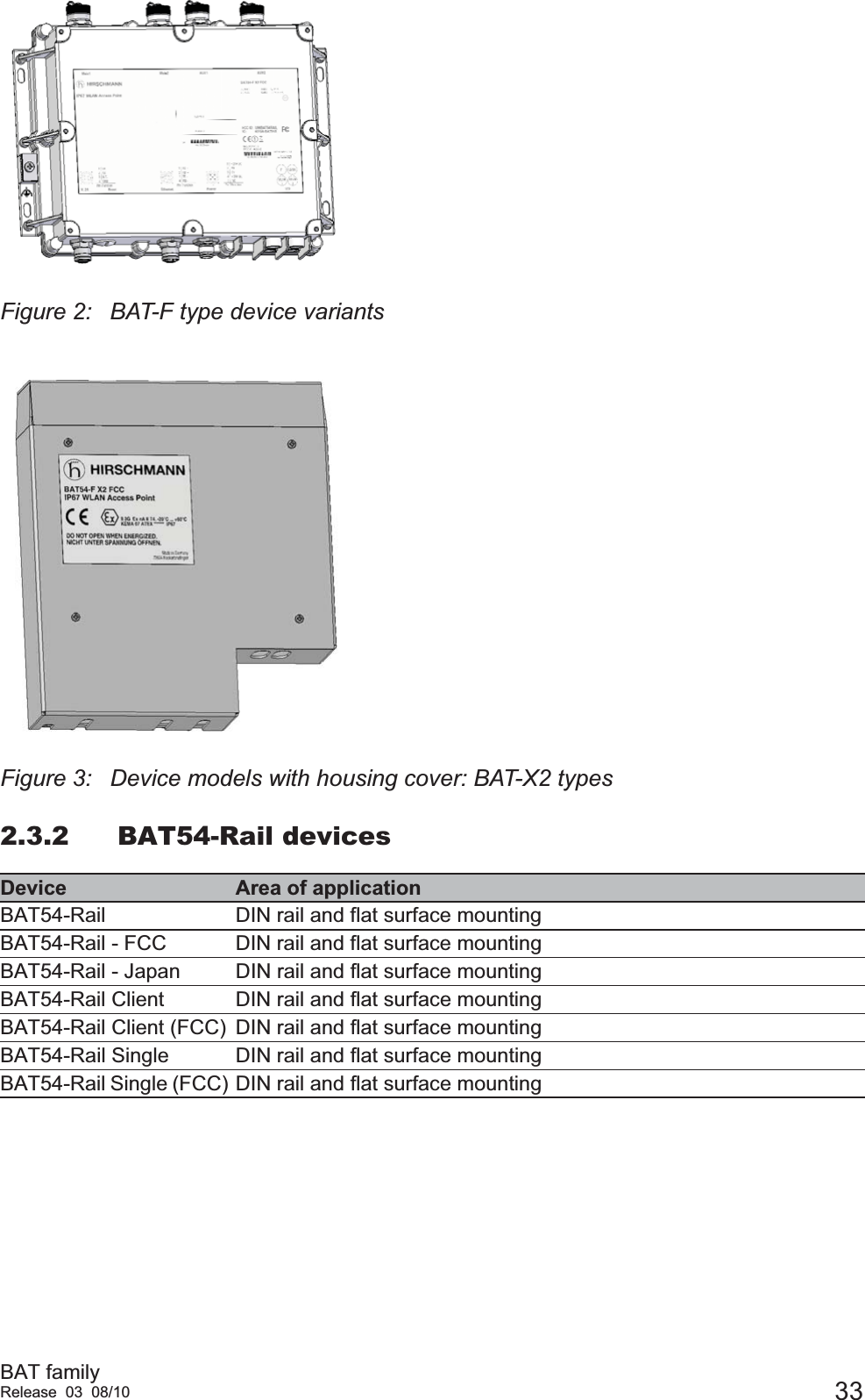
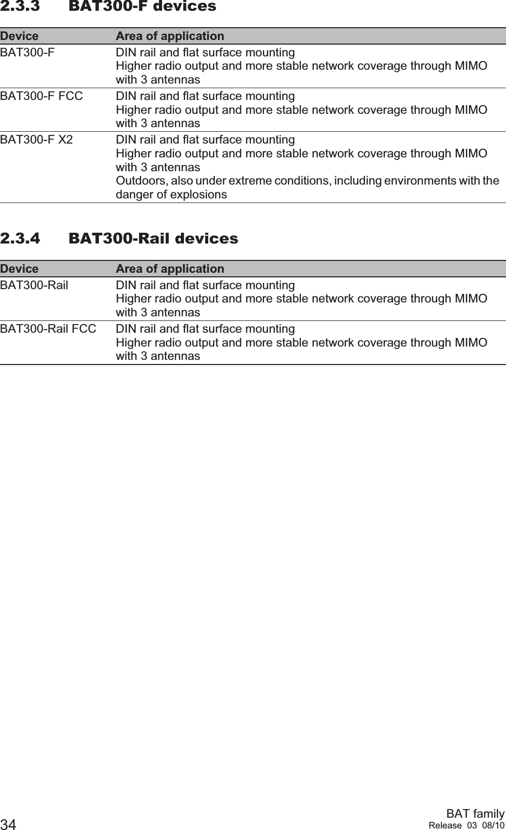
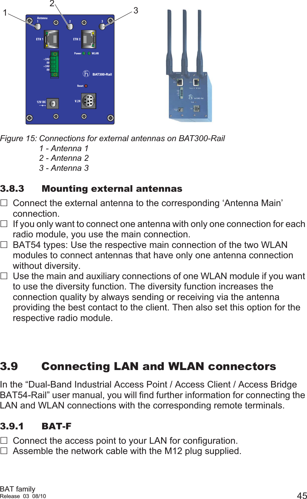
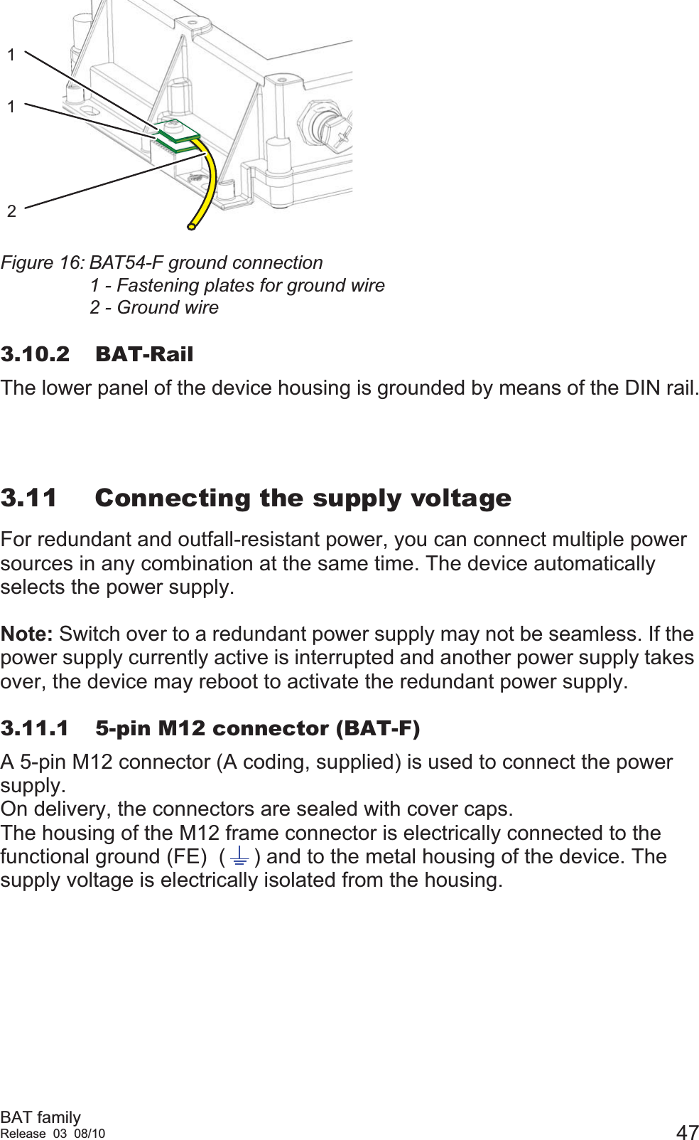
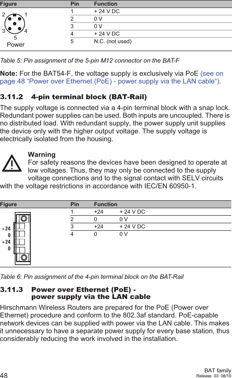
Hirschmann Automation and Control BAT300 802.11a/b/g/n mini-PCI module User Manual Installation Guide BAT Family Release 3

Hirschmann Automation and Control GmbH 802.11a/b/g/n mini-PCI module Installation Guide BAT Family Release 3

User Manual

BAT familyRelease 03 08/10Technical SupportHAC.Support@Belden.comUser ManualInstallationDual-Band Industrial Access Point /Access Client / Access BridgeBAT Family BAT54-RailWLAN2WLAN1M1Aux1 Aux2BAT300-RaBAT54-Rail ClientAuxMainBAT54-FBAT54-RailBAT300-RailBAT54-Rail Client41231234PinTXRXN.C.GNDFunctionV.2 41234PinTD+RD+TD-RD-Function4123Ethernet4321512345Pin+24V DC0 V0 V+24V DCN.C.FunctionReset Power LEDMain 1 Main 2 AUX 1 AUX 2BAT54-FIP67 WLAN Access PointLS/DAPWLAN2WLAN1Uin : 24 VDCUin : 48 VDCCLASS 2CLASS 2Iin : 400 mAIin : 170 mA (PoE)41231234PinTXRXN.C.GNDFunctionV.2 4 Reset LEDMain  AUX BAT54-F ClientIP67 WLAN Access PointUin : 24 VDCUin : 48 VDCCLASS 2CLASS 2Iin : 420 mAIin : 170 mA (PoE)WLAN1234PinTD+RD+TD-RD-Function4123Ethernet4321512345Pin+24V DC0 V0 V+24V DCN.C.FunctionPowerLS/DAPNC 41231234PinTXRXN.C.GNDFunctionV.2 41234PinTD+RD+TD-RD-Function4123Ethernet4321512345Pin+24V DC0 V0 V+24V DCN.C.FunctionReset Power LEDAntenna 1 Antenna 2 Antenna 3BAT300-FIP67 WLAN Access PointLS/DAPUin : 24 VDCUin : 48 VDCCLASS 2CLASS 2Iin : 420 mAIin : 170 mA (PoE)WLANNCBAT54-F SingleBAT54-F Client BAT300-F41231234PinTXRXN.C.GNDFunctionV.2 41234PinTD+RD+TD-RD-Function4123Ethernet 2Reset LEDMain  AUX BAT54-F SingleIP67 WLAN Access PointUin : 24 VDCUin : 48 VDCCLASS 2CLASS 2Iin : 420 mAIin : 170 mA (PoE)1234PinTD+RD+TD-RD-Function4123Ethernet 1WLANPLS/DA2LS/DA1xBAT54-Rail SingleMain AuxResetV.2412V DC+24V0V+24V0VETHWLANPBAT54-Rail Single
The naming of copyrighted trademarks in this manual, even when not specially indicated, should not be taken to mean that these names may be considered as free in the sense of the trademark and tradename protection law and hence that they may be freely used by anyone.© 2010 Hirschmann Automation and Control GmbHManuals and software are protected by copyright. All rights reserved. The copying, reproduction, translation, conversion into any electronic medium or machine scannable form is not permitted, either in whole or in part. An exception is the preparation of a backup copy of the software for your own use. For devices with embedded software, the end-user license agreement on the enclosed CD applies.The performance features described here are binding only if they have been expressly agreed when the contract was made. This document was produced by Hirschmann Automation and Control GmbH according to the best of the company's knowledge. Hirschmann reserves the right to change the contents of this document without prior notice. Hirschmann can give no guarantee in respect of the correctness or accuracy of the information in this document.Hirschmann can accept no responsibility for damages, resulting from the use of the network components or the associated operating software. In addition, we refer to the conditions of use specified in the license contract.You can get the latest version of this manual on the Internet at the Hirschmann product site (www.beldensolutions.com).Printed in GermanyHirschmann Automation and Control GmbHStuttgarter Str. 45-5172654 NeckartenzlingenGermanyTel.: +49 1805 141538039 726-002-03-0810  – 25.8.10
BAT familyRelease 03 08/10 3ContentsSafety instructions  6About this manual  14Legend 141 System Planning  151.1 WiFi devices  151.1.1 WiFi access points  151.1.2 WiFi clients  151.2 Frequency Bands  161.2.1 The ISM Bands  161.2.2 Government Regulation of the ISM Bands  181.2.3 Anticipating Radio Wave Behavior  182 Device description  202.1 Properties and functions  202.1.1 BAT-F types  212.1.2 BAT-Rail types  212.1.3 BAT54 types  212.1.4 BAT300 types  222.1.5 BAT-BG/BGN types  222.1.6 Other features  222.2 Interfaces and control elements  242.2.1 BAT54-F 242.2.2 BAT54-F Single  252.2.3 BAT54-F Client  262.2.4 BAT300-F 272.2.5 BAT54-Rail 282.2.6 BAT54-Rail Single  292.2.7 BAT54-Rail Client  302.2.8 BAT300-Rail 312.3 Device models  322.3.1 BAT54-F devices  322.3.2 BAT54-Rail devices  332.3.3 BAT300-F devices  342.3.4 BAT300-Rail devices  342.3.5 BAT-BG/BGN devices  35
4BAT familyRelease 03 08/103 Assembly and start-up  363.1 Installing the device  363.2 Unpacking and checking  363.3 Putting components together (BAT-F)  373.4 Selecting the location for mounting/setting up  373.5 Mounting outdoors (BAT-F)  373.5.1 Lightning protection  373.5.2 Pole mounting  383.6 DIN rail mounting (BAT-Rail)  393.7 Flat surface mounting  403.7.1 BAT-F 403.7.2 BAT-Rail 403.8 Mounting/connecting external antennas  413.8.1 Connections for external antennas on BAT-F  413.8.2 Connections for external antennas on BAT-Rail  433.8.3 Mounting external antennas  453.9 Connecting LAN and WLAN connectors  453.9.1 BAT-F 453.9.2 BAT-Rail 463.10 Grounding 463.10.1 BAT-F 463.10.2 BAT-Rail 473.11 Connecting the supply voltage  473.11.1 5-pin M12 connector (BAT-F)  473.11.2 4-pin terminal block (BAT-Rail)  483.11.3 Power over Ethernet (PoE) - power supply via the LAN cable  483.12 Connecting the data lines  493.12.1 10/100 Mbit/s twisted pair connection  493.12.2 10/100 Mbit/s twisted pair connection  503.13 Installing the BAT-F X2 housing cover   513.14 Startup procedure  533.14.1 BAT-F 533.14.2 BAT-Rail 533.15 Finding and configuring devices  53
BAT familyRelease 03 08/10 53.16 Installing external antennas  543.17 Display elements  563.18 Operation element (reset button)  593.18.1 Functions 593.18.2 BAT-F 603.18.3 BAT-Rail 603.19 Basic set-up  623.20 Disassembly 634 Technical data  64A Further Support  73
6BAT familyRelease 03 08/10Safety instructionsNotes on safetyThis manual contains instructions to be observed for ensuring your personal safety and for preventing damage. The warnings appear next to a warning triangle with a different heading depending on the degree of danger posed:Danger!  Means that death, serious physical injury or significant damage to property will occur if the corresponding safety measures are not carried out. Warning!  Means that death, serious physical injury or significant damage to property could occur if the corresponding safety measures are not carried out.Caution!  Means that minor physical injury or damage to property can occur if the required safety measures are not carried out.Note: Contains important information on the product, on how to manage the product, or on the respective section of the documentation to which your special attention is being drawn.Certified usageThe device may only be employed for the purposes described in the catalog and technical description, and only in conjunction with external devices and components recommended or approved by the manufacturer. The product can only be operated cor-rectly and safely if it is transported, stored, installed and assembled pro-perly and correctly. Furthermore, it must be operated and serviced carefully.Supply voltageThe devices are designed for operation with extra-low voltage (SELV). Accordingly, SELV circuits with voltage restrictions in accordance with IEC/EN 60950-1 may be connected to the supply voltage connectors.The supply voltage is electrically isolated from the housing.Use undamaged parts.For BAT300-Rail: Make sure that the DC power supply line has a maximum length of 3 meters.
BAT familyRelease 03 08/10 7Relevant for North America: For use in Class 2 circuits.Only use copper wire/conductors of class 1, 75 °C (167 °F).Relevant for North America: For use in Class 2 circuits.The device may only be connected to a supply voltage of class 2 that fulfills the requirements of the National Electrical Code, Table 11(b). If the voltage is being supplied redundantly (two different voltage sources), the combined supply voltages must fulfill the requirements of the National Electrical Code, Table 11(b).Shielding groundThe shield of the connectable twisted pair cables is connected to the metal casing of the device as a conductor.Beware of possible short circuits when connecting a cable section with conductive shielding braiding.HousingOnly technicians authorized by the manufacturer are permitted to open the housing.Make sure that the electrical installation meets local or nationally applicable safety regulations.Warning!Never insert sharp objects (small screwdrivers, wires, etc.) into the inside of the product. There is the risk of an electric shock.BAT-F types:A separate screw connector on the housing is provided for the functional ground (FE). This is indicated by the functional ground symbol ( ). The functional ground is electrically connected to the switching ground and the metal housing of the device.BAT-Rail types:The lower panel of the device housing is grounded by means of the DIN rail.If installed in a living area or office environment, the device must be operated exclusively in switch cabinets with fire protection characteristics according to EN 60950-1.EnvironmentThe device may only be operated at the ambient temperature (temperature of the ambient air at a distance of up to 5 cm (1.97 in) from the device) and relative air humidity specified in the technical data.Install the device in a location where the climatic threshold values specified in the technical data will be observed.Use the device only in an environment within the contamination level specified in the technical data.
8BAT familyRelease 03 08/10When installing external antennas, adhere to the regulations of the country in which you are operating the WLAN device.In ambient temperatures under -10 °C, use cabling designed for minimum temperatures.Relevant for use in Ex zone 2 according to ATEX 95 (ATEX 100a): Only products labeled accordingly may be operated in Ex zone 2.When operating the BAT-300F X2 types in Ex zone 2, the following applies:II 3GEx nA II T4 -20°C ... +55°CKEMA 07 ATEX 0124 XWhen operating the BAT-54F X2 types in Ex zone 2, the following applies:II 3GEx nA II T4 -20°C ... +60°CKEMA 07 ATEX 0124 XDO NOT OPEN THE DEVICE WHEN IT IS ELECTRICALLY CHARGED.DO NOT DETACH ANY CONNECTORS WHEN THE DEVICE IS ELECTRICALLY CHARGED.DO NOT REMOVE THE LABELED HOUSING COVER.The BAT-F X2 (FCC) types are installed with a housing cover - as mounted in the state on delivery.Special conditions for safe useProvisions shall be made to prevent the rated voltage from being exceeded by transient disturbances of more than 40 %.When the temperature under rated conditions exceeds 70 °C at the cable or conduit entry point, or 80 °C at the branching point of the conductors, the temperature specification of the selected cable shall be in compliance with the actual measured temperature values.Temperature Code T4 Ambient –20 °C … +55 °CList of Standards EN 60079-0: 2006EN 60079-15: 2005CLC/TR 50427: Dez. 2004Temperature Code T4 Ambient –20 °C … +60 °CList of Standards EN 60079-0: 2006EN 60079-15: 2005CLC/TR 50427: Dez. 2004
BAT familyRelease 03 08/10 9Lightning protectionWhen you mount devices and / or antennas outdoors, there is a risk of them being struck by lightning. Additionally, there is the risk of voltage surges being transmitted into the interior of the building. It is your responsibility to take appropriate measures to mitigate the effects of lightning strikes. Make sure the equipment is installed by a licensed electrician in accordance with local, regional and national regulations for codes and standards (such as VDE 0182 and IEC 62305) and according to best practices for your application and environment. WarningWhen you mount devices outside buildings, there is a risk of them being struck by lightning. Additionally, there is the danger of voltage strikes being transmitted into the interior of the building. See the information in the “WLAN Outdoor Guide”, chapter “Lightning and Surge Voltage Protection”. Make sure that your plant designer or installer has carried out suitable lightning prevention measures. Qualification requirements for personnelQualified personnel as understood in this manual and the warning signs, are persons who are familiar with the setup, assembly, startup, and operation of this product and are appropriately qualified for their job. This includes, for example, those persons who have been:Xtrained or directed or authorized to switch on and off, to ground and to label power circuits and devices or systems in accordance with current safety engineering standards;Xtrained or directed in the care and use of appropriate safety equipment in accordance with the current standards of safety engineering;Xtrained in providing first aid.General safety instructionsElectricity is used to operate this equipment. Comply with every detail of the safety requirements specified in the operating instructions regarding the voltages to apply (see page 6).Non-observance of these safety instructions can therefore cause material damage and/or serious injuries.Only appropriately qualified personnel should work on this device or in its vicinity. These personnel must be thoroughly familiar with all the warnings and maintenance procedures in accordance with this operating manual.
10 BAT familyRelease 03 08/10The proper and safe operation of this device depends on proper handling during transport, proper storage and assembly, and conscientious operation and maintenance procedures.Never start operation with damaged components.Only use the devices in accordance with this manual.  In particular, observe all warnings and safety-related information. Any work that may be required on the electrical installation may only be carried out by personnel trained for this purpose.National and international safety regulationsMake sure that the electrical installation meets local or nationally applicable safety regulations.When installing external antennas, adhere to the regulations of the country in which you are operating the WLAN device.CE markingThe devices comply with the regulations contained in the following European directive: 1999/5/ECDirective of the European Parliament and the council for radio installations and telecommunication systems and for the mutual recognition of their conformity.This directive also contains the goals of directive 2004/108/EC of the European Parliament and the council for standardizing the regulations of member states relating to electromagnetic compatibility, and directive 2006/95/EC of the European Parliament and the council for standardizing the regulations of member states relating to electrical equipment to be used within specific voltage ranges, but without applying the lower voltage threshold. This product may be operated in all EU states (EU = European Union) under the condition that it has been configured correctly. In accordance with the above-named EC directive (EC = European Community), the EC conformity declaration will be at the disposal of the relevant authorities at the following address:Hirschmann Automation and Control GmbHStuttgarter Str. 45-5172654 NeckartenzlingenTel.: +49 1805 141538This product can be used in living areas (living area, place of business, small business) and in industrial areas.
BAT familyRelease 03 08/10 11Information on using devices in motor vehicles (e1)Some variants of the devices are e1-certified. Only operate suitably labeled products in motor vehicles.Note: To meet the requirements of directive 1999/5/EG (R&TTE directive) when operating the device in a motor vehicle, do one of the following:XSupply the power to the device via a Power over Ethernet (PoE) Switch or via a power unit that conforms to IEEE 802.3af. You will find information on PoE-compatible Switches from Hirschmann at www.schneider-electric.comXInstall an upstream filter on the 24V DC power supply. You will find information on suitable filters at www.schneider-electric.com.Note: If you are using an e1-certified device in a vehicle and want to be able to drive the vehicle freely within the EU, set the country profile for Germany. This country profile is identical to all the country profiles for EU countries. Do not, however, use any special frequencies, such as BFWA.FCC note:This device complies with part 15 of the FCC rules. Operation is subject to the following two conditions: XThis device may not cause harmful interference, andXThis device must accept any interference received, including interference that may cause undesired operation.Note: This equipment has been tested and found to comply with the limits for a Class B digital device, pursuant to part 15 of the FCC Rules. These limits are designed to provide reasonable protection against harmful interference in a residential installation. This equipment generates, uses and can radiate radio frequency energy and, if not installed and used in accordance with the instructions, may cause harmful interference to radio communications. However, there is no guarantee that interference will not occur in a particular installation. If this equipment does cause harmful interference to radio or television reception, which can be determined by turning the equipment off and on, the user is encouraged to try to correct the interference by one or more of the following measures: Reorient or relocate the receiving antenna.Increase the separation between the equipment and receiver.Connect the equipment into an outlet on a circuit different from that to which the receiver is connected.Consult the dealer or an experienced radio/TV technician for help.Important note:
12 BAT familyRelease 03 08/10This equipment complies with FCC and IC RSS-102 radiation exposure limits set forth for an uncontrolled environment. This equipment should be installed and operated with minimum distance 40 cm (15.8 in, applied to a 23 dBi antenna) between the radiator and your body.The antenna used for this transmitter must not be co-located with any other transmitters within a host device, except in accordance with FCC multi-transmitter product procedures.This transmitter is restricted to indoor use only within the 5.15-5.25 GHz band to reduce potential for harmful interference to co-channel mobile satellite systems.This Class B digital apparatus complies with Canadian ICES-003.Cet appareil numérique de la classe B est conforme à la norme NMB-003 du Canada.To reduce potential radio interference to other users, the antenna type and its gain should be so chosen that the equivalent isotropically radiated power (e.i.r.p.) is not more than that permitted for successful communication.This device has been designed to operate with the antennas listed below in point-to-multipoint systems, and having a maximum gain of 9 dBi:The antennas listed below have been designed for use exclusively in fixed point-to-point systems operating in the 2400-2483 MHz band:Antennas not included in this list are strictly prohibited for use with this device. The required antenna impedance is 50 ohms.Device model Antennas operating with this device modelBAT54-… (FCC) BAT-ANT-N-5A-IP65BAT-ANT-N-6G-IP65BAT-ANT-N-6ABG-IP65BAT-ANT-N-8G-DS-IP65BAT-ANT-N-9A-DS-IP65BAT-ANT-N-LC-G-50m-IP65BAT-ANT-N-LC-G-100m-IP65BAT300-… (FCC) BAT-ANT-N-8G-DS-IP65, BAT-ANT-N-9A-DS-IP65, BAT-ANT-N-MiMoDB-5N-IP65, BAT-ANT-N-MiMo5-9N-IP65Table 1: Antennas for use in point-to-multipoint systemsDevice model Antennas operating with this device modelBAT54-… (FCC) BAT-ANT-N-14G-IP23BAT300-… (FCC) BAT-ANT-N-23A-VH-IP65Table 2: Antennas for use in fixed point-to-point systemsThe antennas listed below have been designed for use exclusively in fixed point-to-point systems operating in the 2400-2483 MHz and 5725-5850 MHz band and having a maximum gain of 23dBi:
BAT familyRelease 03 08/10 13Recycling noteAfter usage, this product must be disposed of properly as electronic waste, in accordance with the current disposal regulations of your county, state and country.
14 BAT familyRelease 03 08/10About this manualThe following manuals are available as PDF files on the CD-ROM supplied:X"Installation" user manualXReference ManualLegendThe symbols used in this manual have the following meanings:XListingWork stepSubheading
BAT familyRelease 03 08/10 151 System Planning1.1 WiFi devices1.1.1 WiFi access pointsWithin the AP / AC offer are several access point devices, providing a choice of:X1 or 2 radios inside the deviceXthroughputXenvironmental ruggedness/ingress protectionXconformance to government-mandated bandwidth restrictionsDevices rated for IP67 are often used for outdoor installations because of their ability to withstand rain, snow and dust storms. IP40 devices are designed primarily for indoor use, but they can be used outdoors when they are installed inside weather-resistant IP67 enclosures.Effective throughput for a WiFi device is heavily affected by overhead considerations, particularly power loss due to the distance between the access point and its power source. Often the real throughput over a WiFi link is only half of the specified nominal throughput.Each radio that operates in an access point requires an antenna.1.1.2 WiFi clientsA client is a radio device that resides in or is connected to a station. The client allows the station to communicate wirelessly with an access point. The PCMCIA card in a laptop that enables the computer to operate wirelessly is a client, and the laptop is the station. Other types of stations might be moving vehicles such as forklifts or I/O modules used in a machine such as a conveyor belt. A client enables its station to operate wirelessly and may enable the station to roam through a Wireless Local Area Network (WLAN) environment without loosing its network connection by switching to the next, strongest signal in the access point array.
16 BAT familyRelease 03 08/101.2 Frequency BandsAP / AC devices communicate in the radio spectrum. They operate in defined bandwidths, and they often share that bandwidth space with other devices. The requirements of your application will determine the frequency band in which you choose to operate and the types of AP / AC devices to select.1.2.1 The ISM BandsThe IEEE manages a series of specifications for local area networking called the 802 family. WiFi devices fall under four 802.11 standards:The 2.4 GHz and 5 GHz bands are reserved for industrial, scientific and medical (ISM) equipment, which uses the radio spectrum for transmitting and receiving data. They are called the ISM bands. Devices operating within the bandwidths shared by AP / AC devices are usually unlicensed.Working in the 2.4 GHz BandSignals in the lower-frequency 2.4 GHz band (802.11b, 802.11g, and sometimes 802.11n) can propagate through obstacles such as wood, untempered glass and drywall better than 5 GHz signals. Therefore lower frequency transmissions can travel longer distances and are sometimes needed in locations where clients are separated from access points by walls, windows, high shelves, etc.The 2.4 MHz bandwidth is such that network throughput often suffers because of device density in the band. Other ISM devices, such as microwave ovens and cordless phones, operate in the band and can take space in the band away from the AP / AC network.Another consideration that can make communications slow, particularly when a WLAN requires many access points for coverage, is the limited channel capacity of the 2.4 GHz band. Each access point in the WLAN operates on a channel that you assign it in the configuration process. As a roaming client traverses the WLAN from access point to access point, it should maintain uninterrupted communication.Standard Frequency Band Transmission Rate802.11a 5 GHz up to 54 Mb/s802.11b 2.4 GHz 5.5 Mb/s11 Mb/s 802.11g 2.4 GHz up to 54 Mb/s802.11n 2.4 and 5 GHz up to 300 Mb/sTable 3: WiFi Frequencies and Speeds
BAT familyRelease 03 08/10 17The 2.4 GHz band provides only 13 channels (only 11 are available in North America), To reduce interference from channel overlap, adjacent channels in the WLAN should be separated by at least 25 MHz. Most users choose to run 3 channels, channels 1, 6, and 11. The illustration below shows an ideal coverage plan where a series of AP / AC access points broadcasting with omnidirectional antennas are arranged by channel to limit the channel overlap.This coverage illustration is considered an ideal WLAN layout, but quite often it cannot be installed so cleanly. Walls inside a building or geographical barriers outdoors often deflect the radio wave transmission. The floor plan in your building, the terrain and landscape in an outdoor application, and the presence of other non-WiFi noise in the band need to be anticipated as part of a network plan before your equipment is purchased, then tested thoroughly as part of the installation process. Schneider Electric recommends that you commission a professional site survey (an independent study of your site requirements) to prepare for the installation of a WLAN (see page 37).Working in the 5 MHz BandOne clear advantage that a signal in the higher-frequency 5 GHz band (802.11a and sometimes 802.11n) has is the availability of multiple channels that do not overlap. In this radio spectrum, at least 8 channels can be supported cleanly. Another advantage is that the band is not populated by legacy ISM devices, so interference is much less likely.There are some disadvantages though. Signals in the 5 MHz band operate well when there is a clear and unobstructed line of sight. They do not propagate well through physical obstacles such as interior walls and doors and outdoor traffic and terrain. Also, some client devices, such as the built-in wireless adapters in many laptops, operate only in the 2.4 GHz band.111661161111111116
18 BAT familyRelease 03 08/10All of the AP / AC access point devices are dual-band, i.e., they operate in both the 2.4 MHz and 5 MHz frequency bands. However, you need to be aware of any bandwidth restrictions at your site when you select your antennas because several of them are band-specific.Here is how the access points perform in terms of transmission rate:1.2.2 Government Regulation of the ISM BandsGovernments control and regulate the allotment of radio spectrum in their airspace. In Europe, for example, band allocation is managed by the European Radiocommunications Office (ERO), and in the United States and Canada by the Federal Communications Commission (FCC).If your AP / AC network is being designed to operate in the United States or Canada, different access point modules are needed than if your network is located in Europe, Asia, or Australia:1.2.3 Anticipating Radio Wave BehaviorBecause WiFi relies on radio bands for data transmission and reception, you need to expect some network behaviors that differ from those on the wired network. These behaviors include:Xthe ways that the transmissions propagate through physical impediments and the atmosphereXthe unbounded nature of radio signalsXthe inherent half-duplex nature of radio transmission and receptionPropagation can be hindered by both visible and invisible impediments.Visible impedimentsVisible impediments include walls, doors, windows and stacked material inside a building. If you have chosen to operate at 2.4 GHz in order to get the signal to propagate through a wall, you also need to know what is behind the wall. A steel reinforcing beam or a mortar and cement fireblock (a physical wall, not a network firewall) will deflect (or block) the radio signal more severely than you might have expected if you assumed you were passing through drywall.If you intend to propagate the signal through windows, you need to be aware of the characteristics of the glass. 2.4 GHz signals can pass through standard window glass relatively cleanly, but tempered or bullet-proof glass severely deflects the signal.If you are planning an outdoor implementation of WiFi, you need to consider the existing terrain over which the signal will pass. If you need to send a signal over a hill or over another building, you need to use an access point and antenna as a bridge. If you are traversing an area that has an unobstructed line of sight between the two points in your link,
BAT familyRelease 03 08/10 19make sure that the line will remain unobstructed as long as you need your network. A signal may work well in the winter when the trees are bare, but it may suffer significant degradation when the leaves bloom. If you are traversing an open field, you need to know whether a new building will be constructed between the two ends of the link.You also need to know that some form of power supply is near each AP / AC access point. If the power is to be delivered over the Ethernet (PoE), remember that the access point must be within 100 m (109 yd) of the Ethernet cabinet.Invisible impedimentsInvisible impediments are the radio signals that compete with your WLAN in the same bandwidth. This competition is more common in the 2.4 MHz band because so many other ISM equipment uses the frequency band. Realize that if your business is involved in microwave work, for example, a 2.4 GHz WLAN will need to compete for bandwidth in the same frequency band. This is also true for Bluetooth and some other unlicensed radio devices. Boundless nature of radio transmissionsAnother key difference between a wired and a wireless network is the fact that wireless radio transmissions will not be contained by the walls of your building. Unlike a wired network where signals travel over a defined path, radio signals bounce off obstacles and penetrate through the boundaries of your facility to the outside world.AP / AC devices are equipped with powerful authentication and encryption features that can help protect your data from unauthorized listeners and traffic. Refer to the AP / AC Configuration and Aministration Guide for details.Half duplex communicationCommunications between a AP / AC access point and its clients or between multiple access points is half-duplex. One end of the link must wait while the other transmits, resulting in slower communications. Wireless should not be used as the sole or primary means of control in a time-critical application.Because communications are via broadcast, messages are sent to all participants in the network. The overall transmission capacity of the AP / AC access point is therefore shared by all the participants.
20 BAT familyRelease 03 08/102 Device description2.1 Properties and functionsThe devices of the BAT family enable you to set up WLANs (Wireless Local Area Networks) in order to connect individual devices (PCs and mobile computers) with a local network. In contrast to a conventional network connection via copper cables and glass fibers, some of the communication is by means of a radio link.The devices of the BAT family can be used for both new installations and for expanding an existing LAN. Thanks to their high level of flexibility, you can combine large, small, mobile and non-mobile locations. Anywhere that high bandwidths, stable operation and network security are required, wireless LAN with the devices of the BAT family provides the ideal solution.The BAT54-F is an access point/access client with a WLAN interface for dualband operation in accordance with IEEE802.11b/g and IEEE802.11a/h, and it is specially designed for outdoor use with protection class IP67. The BAT54-F can be installed quickly and easily using wizards via the Windows configuration software or the Web interface. The wide range of BAT antennas provide the correct solution for every requirement - even out-of-the-box solutions.The devices are designed for the special requirements of industrial automation. They are suitable for outdoor use and in environments with the danger of explosions. They meet the relevant industry standards, provide very high operational reliability, even under extreme conditions, and also long-term reliability and flexibility. The devices operate without fans and have a redundant voltage supply. You can mount the devices on a pole or on a flat surface (e.g. wall).The devices differ with regard to their design, the standards they support and their certifications, as shown in the table below:DesignIndoorBAT-Rail typesOutdoorBAT-F typesTable 4: Range of applications for BAT device types
BAT familyRelease 03 08/10 212.1.1 BAT-F typesThe BAT-F devices have protection class IP65/67. The devices are particularly suitable for field use. You can mount the devices on a pole or on a flat surface (e.g. wall).BAT-X2 typesBAT-X2 devices are suitable for use in environments with the danger of explosions (Ex zone 2 areas according to ATEX 95 / ATEX 100a).2.1.2 BAT-Rail typesBAT-Rail devices are suitable for use on DIN rails and on machines in the production area, as well as on vehicles. You can snap them quickly and simply onto the DIN rail or mount them on a flat surface (e.g. wall). With 5-way redundant voltage supply (4-way for the BAT-Client) and a vibration-resistant metal housing, the devices provide high operational reliability. 2.1.3 BAT54 typesThe BAT54 is a dual-band industrial wireless LAN access point/access client with two independent WLAN modules in accordance with IEEE 802.11a/b/g/h and IEEE 802.11i. In particular, the devices support the security mechanisms, authentication procedures and data encryptions defined in the IEEE 802.11i standard.Radio standards801.11  a/b/g/h/iBAT54 typesEx rangeBAT X2 typesBAT54-RailBAT54-Rail-ClientBAT54-Rail SingleBAT54-FBAT54-F SingleBAT54-F ClientBAT54-F X2BAT54-F Single X2BAT54-F Client X2802.11  a/b/g/h/i/nBAT300 typesBAT300-Rail BAT300-F BAT300-F X2Table 4: Range of applications for BAT device types
22 BAT familyRelease 03 08/102.1.4 BAT300 typesThe BAT300 is a dual-band industrial high-performance wireless LAN access point/access client in accordance with IEEE 802.11a/b/g/h and 802.11n (draft 2.0). The devices provide a higher radio output with a bandwidth of up to 300 Mbit/s. They support MIMO (Multiple Input Multiple Output) and Multipath. The bandwidth is increased by using the multipath transmission by means of reflections. Three antennas for sending and receiving ensure more stable network coverage with fewer shadow areas (see following figure).Figure 1: Schematic representation of MIMO (Multiple Input Multiple Output)2.1.5 BAT-BG/BGN typesBAT-BG/BGN devices only support the use of the 2.4 GHz ISM wave band.Note: Note that the function descriptions for the BAT-BG/BGN devices in this installation guide and in the user manuals for the devices only apply to operation with 2.4 GHz. Hirschmann supports you by providing country profiles. These profiles help you to conform to the requirements of the country in which you are operating the WLAN installation.Make sure you always set the correct country profile.2.1.6 Other featuresFeatures can be managed via a Web browser, via Telnet, with a management software product (such as ConneXview) or locally on the device (V.24 interface).The devices provide high mobility combined with maximum security.BAT300-Rail
BAT familyRelease 03 08/10 23The devices provide you with a large range of features:XSturdy metal housing with protection class IP67 (BAT-F) or protection class IP40 (BAT-Rail)XSecure mounting on a flat surface (e.g. wall), a pole (BAT-F) or a DIN rail (BAT-Rail)XRedundant power supply with two 24 V supplies, Power over Ethernet, and one 12 V supplyXTemperature range –30 °C to +50 °CXWireless LAN interfaces in accordance with IEEE802.11b/g and IEEE802.11a/h or IEEE802.11n (draft 2.0)XCreation of redundant WLAN connections for secure data transmissionXMaximum security, also for point-to-point with encryption in accordance with the IEEE802.11i standardXRS-232 serial interface for configuration, remote access and the provision of a serial gatewayXRadio modules can be operated separately as an access point or access client (apart from BAT-Client types)XFast and reliable roaming and prioritizing, also with 802.1x authenticationXHigh performance operating system with a wide range of functions via MultiSSID, VLAN, Rapid SpanningTree, RADIUS server, IP router, firewall, DHCP server, etc.XManagement software for Windows, Web configuration, Telnet interface and management via SNMPAntenna technology for a high quality signalXFor operation indoors and outdoorsXMounting with cables providedXSecure wall and pole bracketXOptimized distribution and performance for every applicationXLong transmission distancesXDesigned for 2.4 GHz and 5 GHz wave bandsCross-platform WLAN managementXA standardized, cross-platform management system for transparent and efficient network monitoring (SNMP)XWindows management suite: LANconfig, LANmonitor, WLANmonitorXDirect management via Web browser (HTTP, HTTPS)XCommand line level: TelNetXCan always be reached via serial interfaceXComplete and partial configuration of multiple devices via scriptingXWLANmonitor for convenient monitoring of WLANs with Rogue AP DetectionXMonitoring of all BAT family devices as clients and as access points in an application
24 BAT familyRelease 03 08/10Communication via all levelsThe addition, to the BAT wireless transmission system, of the RS20/RS30/RS40 open rail range of switches, the MICE range of switches, the MACH range of backbone switches, the EAGLE security system, and products for the LION control room, provides continuous communication across all levels of the company.2.2 Interfaces and control elements2.2.1 BAT54-FThe device is equipped with the following connectors and operation elements:9 8 7 631 42 5 541231234PinTXRXN.C.GNDFunctionV.241234PinTD+RD+TD-RD-Function4123Ethernet4321512345Pin+24V DC0 V0 V+24V DCN.C.FunctionReset Power LEDMain 1 Main 2 AUX 1 AUX 2BAT54-FIP67 WLAN Access PointLS/DAPWLAN2WLAN1Uin : 24 VDCUin : 48 VDCCLASS 2CLASS 2Iin : 400 mAIin : 170 mA (PoE)LS/DAPowerWLAN2WLAN1
BAT familyRelease 03 08/10 252.2.2 BAT54-F SingleThe device is equipped with the following connectors and operation elements:Interfaces and display and control elements1 V.24 Serial interface, 4-pin M12 socket with A coding, data rate min. 19.2 kbit/s, max. 115 kbit/s, connector for serial configuration cable2 Reset Reset button behind a removable IP67 cap restarts the device or resets the configuration3 Ethernet Ethernet port:4-pin M12 socket with D coding, 10/100BASE-TX, Autosensing, Power over Ethernet (PoE), automatic MDI/MDIX recognition (no crossover cable required)4 Power Power supply connector for safety extra-low voltage (SELV/PELV), 5-pin M12 plug5 LED 4 display elements (power, LS/DA, WLAN1, WLAN2)6 AUX 2 Auxiliary connector for the second WLAN module for connecting external antennas7 AUX 1 Auxiliary connector for the first WLAN module for connecting external antennas8 Main 2 Main connector for the second WLAN module for connecting external antennas9 Main 1 Main connector for the first WLAN module for connecting external antennas9 8 7 631 42 5 541231234PinTXRXN.C.GNDFunctionV.241234PinTD+RD+TD-RD-Function4123Ethernet4321512345Pin+24V DC0 V0 V+24V DCN.C.FunctionReset Power LEDMain 1 Main 2 AUX 1 AUX 2BAT54-FIP67 WLAN Access PointLS/DAPWLAN2WLAN1Uin : 24 VDCUin : 48 VDCCLASS 2CLASS 2Iin : 400 mAIin : 170 mA (PoE)LS/DAPowerWLAN2WLAN1
26 BAT familyRelease 03 08/102.2.3 BAT54-F ClientThe device is equipped with the following connectors and operation elements:Interfaces and display and control elements1 V.24 Serial interface, 4-pin M12 socket with A coding, data rate min. 19.2 kbit/s, max. 115 kbit/s, connector for serial configuration cable2 Reset Reset button behind a removable IP67 cap restarts the device or resets the configuration3 Ethernet 2Second Ethernet port4-pin M12 socket with D coding, 10/100BASE-TX, Autosensing, Power over Ethernet (PoE), automatic MDI/MDIX recognition (no crossover cable required)4 Ethernet 1First Ethernet port4-pin M12 socket with D coding, 10/100BASE-TX, Autosensing, Power over Ethernet (PoE), automatic MDI/MDIX recognition (no crossover cable required)5 LED 4 display elements (power, LS/DA1, LS/DA2, WLAN)6 AUX Auxiliary connector for the WLAN module for connecting external antennas7 Main Main connector for the WLAN module for connecting external antennas9 8 7 631 42 5 541231234PinTXRXN.C.GNDFunctionV.241234PinTD+RD+TD-RD-Function4123Ethernet4321512345Pin+24V DC0 V0 V+24V DCN.C.FunctionReset Power LEDMain 1 Main 2 AUX 1 AUX 2BAT54-FIP67 WLAN Access PointLS/DAPWLAN2WLAN1Uin : 24 VDCUin : 48 VDCCLASS 2CLASS 2Iin : 400 mAIin : 170 mA (PoE)LS/DAPowerWLAN2WLAN1
BAT familyRelease 03 08/10 272.2.4 BAT300-FThe device is equipped with the following connectors and operation elements:Interfaces and display and control elements1 V.24 Serial interface, 4-pin M12 socket with A coding, data rate min. 19.2 kbit/s, max. 115 kbit/s, connector for serial configuration cable2 Reset Reset button behind a removable IP67 cap restarts the device or resets the configuration3 Ethernet Ethernet port:4-pin M12 socket with D coding, 10/100BASE-TX, Autosensing, Power over Ethernet (PoE), automatic MDI/MDIX recognition (no crossover cable required)4 Power Power supply connector for safety extra-low voltage (SELV/PELV), 5-pin M12 plug5 LED 4 display elements (power, LS/DA, WLAN, NC)6 AUX Auxiliary connector for the WLAN module for connecting external antennas7 Main Main connector for the WLAN module for connecting external antennas9 8 7 631 42 5 541231234PinTXRXN.C.GNDFunctionV.241234PinTD+RD+TD-RD-Function4123Ethernet4321512345Pin+24V DC0 V0 V+24V DCN.C.FunctionReset Power LEDMain 1 Main 2 AUX 1 AUX 2BAT54-FIP67 WLAN Access PointLS/DAPWLAN2WLAN1Uin : 24 VDCUin : 48 VDCCLASS 2CLASS 2Iin : 400 mAIin : 170 mA (PoE)LS/DAPowerWLAN2WLAN1
28 BAT familyRelease 03 08/102.2.5 BAT54-RailThe device is equipped with the following connectors and operation elements:Interfaces and display and control elements1 V.24 Serial interface, 4-pin M12 socket with A coding, data rate min. 19.2 kbit/s, max. 115 kbit/s, connector for serial configuration cable2 Reset Reset button behind a removable IP67 cap restarts the device or resets the configuration3 Ethernet Ethernet port:4-pin M12 socket with D coding, 10/100BASE-TX, Autosensing, Power over Ethernet (PoE), automatic MDI/MDIX recognition (no crossover cable required)4 Power Power supply connector for safety extra-low voltage (SELV/PELV), 5-pin M12 plug5 LED 4 display elements (power, LS/DA, WLAN, NC)6 Antenna 3Main connector for the WLAN module for connecting the third external antenna7 Antenna 2Main connector for the WLAN module for connecting the second external antenna8 Antenna 1Main connector for the WLAN module for connecting the first external antennaBAT54-RailWLAN2WLAN1M1Aux1 Aux2Main 1 Main 21112345691078
BAT familyRelease 03 08/10 292.2.6 BAT54-Rail SingleThe device is equipped with the following connectors and operation elements:Interfaces and display and control elements1 ETH1 First Ethernet port10/100BASE-TX, Autosensing, Power over Ethernet (PoE), automatic MDI/MDIX recognition (no crossover cable required)2+24V0VPower, power supply connector for safety extra-low voltage (SELV/PELV)3 12V DC Power, power supply connector for safety extra-low voltage (SELV/PELV)4 AUX 1 Auxiliary connector for the first WLAN module for connecting external antennas5 AUX 2 Auxiliary connector for the second WLAN module for connecting external antennas6 V.24 MiniDin serial interface, data rate min. 19.2 kbit/s, max. 115 kbit/s, connector for serial configuration cable7 Reset Reset button to restart device or reset the configuration8 LED 4 display elements (power, M1, WLAN1, WLAN2)9 ETH2 Second Ethernet port10/100BASE-TX, Autosensing, Power over Ethernet (PoE), automatic MDI/MDIX recognition (no crossover cable required)10 Main 2 Main connector for the second WLAN module for connecting external antennas11 Main 1 Main connector for the first WLAN module for connecting external antennas81234756xBAT54-Rail SingleMain AuxResetV.2412V DC+24V0V+24V0VETHWLANP
30 BAT familyRelease 03 08/102.2.7 BAT54-Rail ClientThe device is equipped with the following connectors and operation elements:Interfaces and display and control elements1 ETH Ethernet port:10/100BASE-TX, Autosensing, Power over Ethernet (PoE), automatic MDI/MDIX recognition (no crossover cable required)2 +24V0VPower, power supply connector for safety extra-low voltage (SELV/PELV)3 12V DC Power, power supply connector for safety extra-low voltage (SELV/PELV)4 V.24 MiniDin serial interface, data rate min. 19.2 kbit/s, max. 115 kbit/s, connector for serial configuration cable5 Reset Reset button to restart device or reset the configuration6 LED 2 display elements (power, WLAN)7 AUX Auxiliary connector for the WLAN module for connecting external antennas8 Main Main connector for the WLAN module for connecting external antennasBAT54-Rail ClientAuxMain81234756
BAT familyRelease 03 08/10 312.2.8 BAT300-RailThe device is equipped with the following connectors and operation elements:Interfaces and display and control elements1 ETH Ethernet port:10/100BASE-TX, Autosensing, Power over Ethernet (PoE), automatic MDI/MDIX recognition (no crossover cable required)2+24V0VPower, power supply connector for safety extra-low voltage (SELV/PELV)3 12V DC Power, power supply connector for safety extra-low voltage (SELV/PELV)4 V.24 MiniDin serial interface, data rate min. 19.2 kbit/s, max. 115 kbit/s, connector for serial configuration cable5 Reset Reset button to restart device or reset the configuration6 LED 2 display elements (power, WLAN)7 AUX Auxiliary connector for the WLAN module for connecting external antennas8 Main Main connector for the WLAN module for connecting external antennasBAT300-Rail10123947856
32 BAT familyRelease 03 08/102.3 Device models2.3.1 BAT54-F devicesInterfaces and display and control elements1 ETH1 First Ethernet port10/100BASE-TX, Autosensing, Power over Ethernet (PoE), automatic MDI/MDIX recognition (no crossover cable required)2 +24V0VPower, power supply connector for safety extra-low voltage (SELV/PELV)3 12V DC Power, power supply connector for safety extra-low voltage (SELV/PELV)4 V.24 MiniDin serial interface, data rate min. 19.2 kbit/s, max. 115 kbit/s, connector for serial configuration cable5 Reset Reset button to restart device or reset the configuration6 LED 2 display elements (power, WLAN)7 ETH2 Second Ethernet port10/100BASE-TX, Autosensing, Power over Ethernet (PoE), automatic MDI/MDIX recognition (no crossover cable required)8 Antenna 3Main connector for the WLAN module for connecting the third external antenna9 Antenna 2Main connector for the WLAN module for connecting the second external antenna10 Antenna 1Main connector for the WLAN module for connecting the first external antennaDevice Area of applicationBAT54-F FCC Outdoors, also hazardous environmentsBAT54-F Outdoors, also hazardous environmentsBAT54-F X2 FCC Outdoors, also under extreme conditions, including environments with the danger of explosionsBAT54-F X2 Outdoors, also under extreme conditions, including environments with the danger of explosionsBAT54-F Client Outdoors, also hazardous environmentsBAT54-F Client FCC Outdoors, also hazardous environmentsBAT54-F Single Outdoors, also hazardous environmentsBAT54-F Single FCC Outdoors, also hazardous environments
BAT familyRelease 03 08/10 33Figure 2: BAT-F type device variantsFigure 3: Device models with housing cover: BAT-X2 types2.3.2 BAT54-Rail devicesDevice Area of applicationBAT54-Rail DIN rail and flat surface mountingBAT54-Rail - FCC DIN rail and flat surface mountingBAT54-Rail - Japan DIN rail and flat surface mountingBAT54-Rail Client DIN rail and flat surface mountingBAT54-Rail Client (FCC) DIN rail and flat surface mountingBAT54-Rail Single DIN rail and flat surface mountingBAT54-Rail Single (FCC) DIN rail and flat surface mounting
34 BAT familyRelease 03 08/102.3.3 BAT300-F devices2.3.4 BAT300-Rail devicesDevice Area of applicationBAT300-F DIN rail and flat surface mountingHigher radio output and more stable network coverage through MIMO with 3 antennasBAT300-F FCC DIN rail and flat surface mountingHigher radio output and more stable network coverage through MIMO with 3 antennasBAT300-F X2 DIN rail and flat surface mountingHigher radio output and more stable network coverage through MIMO with 3 antennasOutdoors, also under extreme conditions, including environments with the danger of explosionsDevice Area of applicationBAT300-Rail DIN rail and flat surface mountingHigher radio output and more stable network coverage through MIMO with 3 antennasBAT300-Rail FCC DIN rail and flat surface mountingHigher radio output and more stable network coverage through MIMO with 3 antennas
BAT familyRelease 03 08/10 352.3.5 BAT-BG/BGN devicesDevice Area of applicationBAT300-Rail BGN Using the 2.4 GHz ISM wave bandDIN rail and flat surface mountingHigher radio output and more stable network coverage through MIMO with 3 antennasBAT300-F BGN Using the 2.4 GHz ISM wave bandHigher radio output and more stable network coverage through MIMO with 3 antennasBAT54-F Client BG Using the 2.4 GHz ISM wave bandOutdoors, also hazardous environmentsBAT54-F Single BG Using the 2.4 GHz ISM wave bandOutdoors, also hazardous environmentsBAT54-F BG  Using the 2.4 GHz ISM wave bandOutdoors, also hazardous environmentsBAT54-F X2 BG Using the 2.4 GHz ISM wave bandOutdoors, also under extreme conditions, including environments with the danger of explosionsBAT54-Rail Client BG Using the 2.4 GHz ISM wave bandDIN rail and flat surface mountingBAT54-Rail BG Using the 2.4 GHz ISM wave bandDIN rail and flat surface mountingBAT54-Rail Single BG Using the 2.4 GHz ISM wave bandDIN rail and flat surface mountingBAT300-F X2 BGN Using the 2.4 GHz ISM wave bandOutdoors, also under extreme conditions, including environments with the danger of explosionsHigher radio output and more stable network coverage through MIMO with 3 antennas
36 BAT familyRelease 03 08/103 Assembly and start-up3.1 Installing the deviceThe devices have been developed for practical application in a harsh industrial environment.On delivery, the device is ready for operation. The following procedure has been proven to be successful for the assembly of the device:XUnpacking and checkingXPutting components together (BAT-F)XSelecting the location for mounting/setting upXMounting outdoors (BAT-F)XDIN rail mounting (BAT-Rail)XFlat surface mountingXMounting/connecting external antennasXConnecting LAN and WLAN connectorsXConnecting the supply voltageXGroundingXInstalling the data linesXInstalling the housing cover BAT-F X2XStarting upXFinding and configuring devicesXInstalling external antennasXEstablishing basic settingsBefore installing and starting up the device, note the safety instructions (see page 6 onwards).3.2 Unpacking and checkingCheck that the contents of the package are complete (see page 69 “Scope of delivery“).Check the individual parts for transport damage.
BAT familyRelease 03 08/10 373.3 Putting components together (BAT-F)To protect the exposed contacts of the components from dirt, the individual system components must be connected in a dry and clean area. Seal unused ports with the cover caps supplied.Note: Connectors are not electrical isolating devices.Therefore, first plug the connector into the power supply plug, then switch on the power supply.Note: Protection class IP67 is only achieved if all the connected components also fulfill protection class IP67.Cover unused connectors with the cover caps supplied.Only connect plugs and other components that fulfill protection class IP 67, and that are certified for a temperature range from -30 °C to +55 °C (-22 °F to +131 °F).3.4 Selecting the location for mounting/setting upSet up/mount the device in a location where the ambient conditions comply with the specified listed in the technical data.3.5 Mounting outdoors (BAT-F)Note: Set up the antenna close to the device. Use the shortest antenna cable possible to minimize attenuation.Note: Cable connections are subject to corrosion in outdoor installations.Seal the outdoor cable connectors with water- and weather-resistant tape.3.5.1 Lightning protectionNote the safety instructions for lightning protection (see the datasheet for lightning protection or the WLAN Outdoor Guide).If possible, avoid installing in locations with a high risk of lightning. This applies in particular to installing antennas.The antenna should not be the highest point in the area. If this is the case, use a separate lightning conductor to divert lightning strikes.
38 BAT familyRelease 03 08/10WarningLightening protection is an indispensible part of your outdoor antenna installation. It protects your sensitive electronic devices from transient or electrostatic discharges to the antenna.WarningAntennas placed outdoors must be within the catchment area of a lightening conductor. Make sure that there is lightening protection equipotential bonding for all conductive systems leading from outdoors. When implementing your lightening protection concept, make sure you meet the requirements of standards VDE 0182 and IEC 62305.Hirschmann recommends using the Hirschmann BAT Protector as a lightening protection (see on page 69 “Accessories“).WarningInstalling this lightening protection element between an antenna and a BAT-F does not alone provide sufficient protection against a lightening strike. The BAT Protector lightening protection element only works as part of a comprehensive lightening protection concept. If you have any questions relating to this, contact a qualified dealer.Note: The requirements of EN61000-4-5, surge test on power supply lines, are only met if a Blitzductor VT AD 24V, article No. 918 402, is used.Manufacturer: DEHN+SÖHNE GmbH+Co.KG, Hans Dehn Str.1, Postfach 1640, D-92306 Neumarkt.WarningConnect the external antenna, the housing ground and the lightening protection to the same ground system, e.g. to the building ground.For further information on lightning protection, see the “WLAN Outdoor Guide”.3.5.2 Pole mountingThe BAT-F devices are suitable for pole mounting with the additional BAT-F pole mounting set (see on page 69 “Accessories“).The BAT-F pole mounting set is designed for:XPole diameter: 37 mm to 60 mm (1.46 in to 2.36 in)XMaximum permitted wind speed: 220 km/h (136 mph).
BAT familyRelease 03 08/10 39Figure 4: BAT-F pole mounting set3.6 DIN rail mounting (BAT-Rail)Mount the device on a 35 mm DIN rail in accordance with DIN EN 60175.Attach the upper snap-in guide of the device into the DIN rail and press it down against the DIN rail until it snaps into place.Note: The shielding ground of the industrial connectable twisted pair lines is connected to the lower panel as a conductor.Figure 5: Mounting on the DIN rail
40 BAT familyRelease 03 08/103.7 Flat surface mounting3.7.1 BAT-FDrill holes at the installation point.Mount the device on a flat surface with four M5 screws.Figure 6: BAT-F, mounting on a flat surface (e.g. wall)3.7.2 BAT-RailFigure 7: BAT-Rail, wall mountingFasten on the wall mounting plate (width 120 mm / 4.73 in) (see on page 69 “Accessories“) on a level wall surface using four screws.Mount the device on the wall plate as shown in the illustration. Attach the upper snap-in guide of the device into the rail and press it down against the rail until it snaps into place.BAT300-Rail
BAT familyRelease 03 08/10 413.8 Mounting/connecting external antennas3.8.1 Connections for external antennas on BAT-FThe BAT-F devices have two to four connections for connecting external antennas. These connections are N sockets.The housing of the N socket and the signal connection are electrically connected to the switching ground, the functional ground (FE) ( ) and the metal housing of the device.On delivery, the connectors are sealed with cover caps.Unscrew the cover caps from the connectors to which you want to connect external antennas.Note: Insert the terminators supplied into unused sockets in order to avoid radio signals from one WLAN module being received by the other WLAN module. BAT54-FFigure 8: Connections for external antennas on BAT54-F1 - Main 12 - Main 23 - AUX 14 - AUX 21 2 3 441231234PinTXRXN.C.GNDFunctionV.2 41234PinTD+RD+TD-RD-Function4123Ethernet4321512345Pin+24V DC0 V0 V+24V DCN.C.FunctionReset Power LEDMain 1 Main 2 AUX 1 AUX 2BAT54-FIP67 WLAN Access PointLS/DAPWLAN2WLAN1Uin : 24 VDCUin : 48 VDCCLASS 2CLASS 2Iin : 400 mAIin : 170 mA (PoE)BAT54-F
42 BAT familyRelease 03 08/10BAT54-F SingleFigure 9: Connections for external antennas on BAT54-F Single1 - Main 2 - AUXBAT54-F ClientFigure 10: Connections for external antennas on BAT54-F Client1 - Main 2 - AUX41231234PinTXRXN.C.GNDFunctionV.2 41234PinTD+RD+TD-RD-Function4123Ethernet 2Reset LEDMain  AUX BAT54-F SingleIP67 WLAN Access PointUin : 24 VDCUin : 48 VDCCLASS 2CLASS 2Iin : 420 mAIin : 170 mA (PoE)1234PinTD+RD+TD-RD-Function4123Ethernet 1WLANPLS/DA2LS/DA11 2BAT54-F Single41231234PinTXRXN.C.GNDFunctionV.2 4 Reset LEDMain  AUX BAT54-F ClientIP67 WLAN Access PointUin : 24 VDCUin : 48 VDCCLASS 2CLASS 2Iin : 420 mAIin : 170 mA (PoE)WLAN1234PinTD+RD+TD-RD-Function4123Ethernet4321512345Pin+24V DC0 V0 V+24V DCN.C.FunctionPowerLS/DAPNC1 2BAT54-F Client
BAT familyRelease 03 08/10 43BAT300-FFigure 11: Connections for external antennas on BAT300-F1 - Antenna 12 - Antenna 23 - Antenna 33.8.2 Connections for external antennas on BAT-RailBAT54-RailThe devices have four Reverse satellite master antenna (SMA) connectors for connecting external antennas.Figure 12: Connections for external antennas on BAT54-Rail1 - Antenna 12 - Antenna 23 - Aux14 - Aux241231234PinTXRXN.C.GNDFunctionV.241234PinTD+RD+TD-RD-Function4123Ethernet4321512345Pin+24V DC0 V0 V+24V DCN.C.FunctionReset Power LEDAntenna 1 Antenna 2 Antenna 3BAT300-FIP67 WLAN Access PointLS/DAPUin : 24 VDCUin : 48 VDCCLASS 2CLASS 2Iin : 420 mAIin : 170 mA (PoE)WLANNC1 2 3BAT300-FBAT54-RailWLAN2WLAN1M1Aux1 Aux21342
44 BAT familyRelease 03 08/10BAT54-Rail SingleThe devices have two Reverse SMA connectors for connecting external antennas.Figure 13: Connections for external antennas on BAT54-Rail Single1 - Main2 - AuxBAT54-Rail ClientThe devices have two Reverse SMA connectors for connecting external antennas.Figure 14: Connections for external antennas on BAT54-Rail Client1 - Main 2 - AuxBAT300-RailThe devices have three Reverse SMA connectors for connecting external antennas. xBAT54-Rail SingleMain AuxResetV.2412V DC+24V0V+24V0VETHWLANP12BAT54-Rail ClientAuxMain12
BAT familyRelease 03 08/10 45Figure 15: Connections for external antennas on BAT300-Rail1 - Antenna 12 - Antenna 23 - Antenna 33.8.3 Mounting external antennasConnect the external antenna to the corresponding ‘Antenna Main’ connection. If you only want to connect one antenna with only one connection for each radio module, you use the main connection.BAT54 types: Use the respective main connection of the two WLAN modules to connect antennas that have only one antenna connection without diversity.Use the main and auxiliary connections of one WLAN module if you want to use the diversity function. The diversity function increases the connection quality by always sending or receiving via the antenna providing the best contact to the client. Then also set this option for the respective radio module.3.9 Connecting LAN and WLAN connectorsIn the “Dual-Band Industrial Access Point / Access Client / Access Bridge BAT54-Rail” user manual, you will find further information for connecting the LAN and WLAN connections with the corresponding remote terminals.3.9.1 BAT-FConnect the access point to your LAN for configuration.Assemble the network cable with the M12 plug supplied.BAT300-Rail123
46 BAT familyRelease 03 08/10Plug the network cable into the LAN connector of the device, and into a free network connection port on your local network (or into a free port on a hub/switch). Alternatively, you can connect the device to a separate PC. The port auto-negotiates upon connection; either a straight or a crossover cable can be used.3.9.2 BAT-RailConnect the access point to your LAN for configuration.Plug the network cable into the LAN connector of the device, and into a free network connection port on your local network (or into a free port on a hub/switch). Alternatively, you can connect the device to a separate PC. The port auto-negotiates upon connection; either a straight or a crossover cable can be used.3.10 Grounding3.10.1 BAT-FA separate anti-torsion screw connector on the housing is provided for the functional ground (FE) . It is indicated by the functional ground symbol  ( ). The functional ground is electrically connected to the switching ground and to the metal housing of the device.For the ground wire, use a copper wire with a minimum cross section of 4 mm2 to 6 mm2 (for North America: AWG 11 to AWG 9) (including any terminal sleeve used), and implement the grounding of the device via the screw connector.Clamp the ground wire between the two rectangular fastening plates - as shown in the figure below - and fasten the screw.Make sure that the ground wire is not in direct contact with the aluminum housing of the device.
BAT familyRelease 03 08/10 47Figure 16: BAT54-F ground connection1 - Fastening plates for ground wire2 - Ground wire3.10.2 BAT-RailThe lower panel of the device housing is grounded by means of the DIN rail.3.11 Connecting the supply voltageFor redundant and outfall-resistant power, you can connect multiple power sources in any combination at the same time. The device automatically selects the power supply.  Note: Switch over to a redundant power supply may not be seamless. If the power supply currently active is interrupted and another power supply takes over, the device may reboot to activate the redundant power supply.3.11.1 5-pin M12 connector (BAT-F)A 5-pin M12 connector (A coding, supplied) is used to connect the power supply.On delivery, the connectors are sealed with cover caps.The housing of the M12 frame connector is electrically connected to the functional ground (FE)  ( ) and to the metal housing of the device. The supply voltage is electrically isolated from the housing.121
48 BAT familyRelease 03 08/10Note: For the BAT54-F, the voltage supply is exclusively via PoE (see on page 48 “Power over Ethernet (PoE) - power supply via the LAN cable“). 3.11.2 4-pin terminal block (BAT-Rail)The supply voltage is connected via a 4-pin terminal block with a snap lock.Redundant power supplies can be used. Both inputs are uncoupled. There is no distributed load. With redundant supply, the power supply unit supplies the device only with the higher output voltage. The supply voltage is electrically isolated from the housing.WarningFor safety reasons the devices have been designed to operate at low voltages. Thus, they may only be connected to the supply voltage connections and to the signal contact with SELV circuits with the voltage restrictions in accordance with IEC/EN 60950-1.3.11.3 Power over Ethernet (PoE) - power supply via the LAN cableHirschmann Wireless Routers are prepared for the PoE (Power over Ethernet) procedure and conform to the 802.3af standard. PoE-capable network devices can be supplied with power via the LAN cable. This makes it unnecessary to have a separate power supply for every base station, thus considerably reducing the work involved in the installation. Figure  Pin Function1+ 24 V DC20 V30 V4+ 24 V DC5 N.C. (not used)Table 5: Pin assignment of the 5-pin M12 connector on the BAT-FFigure  Pin Function1 +24 + 24 V DC20 0 V3 +24 + 24 V DC40 0 VTable 6: Pin assignment of the 4-pin terminal block on the BAT-Rail43215Power
BAT familyRelease 03 08/10 49In the BAT-F devices, the voltage is input via the wire pairs transmitting the signal (IEEE 802.3af, mode A).In the BAT-Rail devices it is also possible to supply the voltage via the free wire pairs.The power supply to the LAN is input centrally, or via a PoE injector or a power hub/power switch.WarningIn a PoE installation, only use devices that adhere to the 802.3af standard! No warranty claims can be made for damage caused by the use of impermissible devices.3.12 Connecting the data lines3.12.1 10/100 Mbit/s twisted pair connectionIn the BAT-F, the 10/100 Mbit/s twisted pair connections are M12 sockets.10/100 Mbit/s ports enable the connection of terminal devices or independent network segments according to the IEEE 802.3 100BASE-TX / 10BASE-T standard. These ports support:XAutonegotiation XAutopolarity XAutocrossing (if autonegotiation is activated)X100 Mbit/s half-duplex mode, 100 Mbit/s full duplex modeX10 Mbit/s half-duplex mode, 10 Mbit/s full duplex modeState on delivery: autonegotiation activated.The TP connector is a 4-pin M12 female connector with D coding. On delivery, the connectors are sealed with cover caps.The housing of the M12 socket is electrically connected to the functional ground (FE)  ( ) and to the metal housing of the device. The connector pins are electrically separated from the functional ground and the metal housing.Figure Pin Function PoE voltage input1 TD+ Transmit Data + V-2 RD+ Receive Data + V+3 TD- Transmit Data - V-4 RD- Receive Data - V+Housing: shieldTable 7:  Pin assignment of a TP/TX interface (M12 socket)
50 BAT familyRelease 03 08/10Use a shielded CAT5 cable.Use a shielded 4-pin M12 plug.Connect the cable shield to the connector housing.The patch cables for operating the device are shown in the following figure: Figure 17: Patch cables for operating the device (1) - Connection cables M12-4 on M12-4, crossed(2) - Connection cables M12-4 on M12-4, 1 to 1(3) - Connection cables M12-4 on RJ45, crossed(4) - Connection cables M12-4 on RJ45, 1 to 1(5) - M12 (MDI)(6) - Shield(7) - M12 (MDI)(8) - M12 (MDI-X via autocrossing port)(9) - RJ45, MDI (terminal device)(10) - RJ45, MDI-X (Switch)3.12.2 10/100 Mbit/s twisted pair connectionIn the BAT-Rail, the 10/100 Mbit/s twisted pair connections are RJ45 sockets.10/100 Mbit/s ports enable the connection of terminal devices or independent network segments according to the IEEE 802.3 100BASE-TX / 10BASE-T standard. These ports support:RX+TX+RX-TX-1234TX+RX+TX-RX-1234TX+RX+TX-RX-1234TX+RX+TX-RX-1234TX+TX-RX+RX-1236TX+RX+TX-RX-1234RX+RX-TX+TX-1236TX+RX+TX-RX-1234(1)(5) (7)(2)(5) (8)(3)(5) (9)(4)(5) (10)(6) (6)(6) (6)(6) (6)(6) (6)
BAT familyRelease 03 08/10 51XAutonegotiation XAutopolarity XAutocrossing (if autonegotiation is activated)X100 Mbit/s half-duplex mode, 100 Mbit/s full duplex modeX10 Mbit/s half-duplex mode, 10 Mbit/s full duplex modeState on delivery: autonegotiation activated.The socket housing is electrically connected to the bottom panel.3.13 Installing the BAT-F X2 housing cover For use in environments with the danger of explosions, the BAT-F X2 device models have an additional housing cover made of stainless sheet steel. On delivery, the housing cover is pre-mounted.Perform the installation in the following steps:Remove the upper part of the housing cover on the device, as shown in the following figure (point 1). Do not try to remove the lower panel of the housing cover from the device.Figure Pin Data PoE voltage input1 RD+ Receive Data + V+2 RD- Receive Data - V+3 TD+ Transmit Data +  V-6 TD- Transmit Data - V-4,5,7,8 Not usedTable 8:  Pin assignment of a TP/TX interface in MDI-X mode, RJ45 socket. PoE voltage input via the wire pairs transmitting the signal (phantom voltage).Figure Pin Data PoE voltage input1 RD+ Receive Data + —2 RD- Receive Data - —3 TD+ Transmit Data + —4—— V-5—— V-6 TD- Transmit Data - —7—— V+8—— V+Table 9:  Pin assignment of a TP/TX interface in MDI-X mode, RJ45 socket. PoE voltage input via the free line pairs (spare pairs).8765432187654321
52 BAT familyRelease 03 08/10Screw the device, including the lower panel of the housing cover, to the mounting surface.Set up the connections to the device.Close the housing cover by replacing the upper part of the housing cover.Fasten the housing cover with four screws, as shown in the following figure (point 2).Figure 18: Mounting the housing cover for BAT-F X2 device models with Ex certification in accordance with ATEX 95 (ATEX 100a)2.1.
BAT familyRelease 03 08/10 533.14 Startup procedure3.14.1 BAT-FConnecting the voltage supply via the 5-pin M12 connector or via the LAN cable (Power over Ethernet) starts the operation of the device.3.14.2 BAT-RailConnecting the voltage supply via the terminal blockPull the terminal block off the device and connect the voltage supply lines.Mount the terminal block for the supply voltage on the front of the device.Connecting the voltage supply via the terminal block starts the operation of the device.Connecting the voltage supply via PoEAlternatively, you can supply the device with the PoE supply voltage via the LAN cable as described above (see on page 48 “Power over Ethernet (PoE) - power supply via the LAN cable“).Connecting the voltage supply via PoE starts the operation of the device.3.15 Finding and configuring devicesApply power to the device before starting the computer for the configuration.AP / AC devices can be configured in the following ways (if the model is equipped with the corresponding interface):XVia the local network (LAN). XVia the radio network (WLAN), if the WLAN encryption (e.g. WPA2) in a device with a wireless interface and in the configuration computer is set or deactivated respectively.XVia the serial configuration interface.Refer to ”ConneXium WiFi TCSG,TSCN Configuration and Administration Guide” on the CD ROM for more details.
54 BAT familyRelease 03 08/103.16 Installing external antennasExternal antennas are required to operate the access point. You will find an overview of the antennas that are supported and can be connected, along with the corresponding technical data, at www.schneider-electric.com.When installing external antennas, adhere to the regulations of the country in which you are operating the WLAN device, and to the general operating permission and the maximum emission levels.Transmission powerThe operator of a WLAN radio installation must adhere to the applicable transmission threshold values. Use the LANconfig or the Webconfig to start the configuration of the device. (This software is located on the CD provided.)Go to the settings for Wireless LAN.Enter the country in which you are installing the device (see the following figure):
BAT familyRelease 03 08/10 55Open the configuration for the physical interface to which you are connecting the antenna. On the Radio tab you will find an entry field for the antenna gain (see the following figure):
56 BAT familyRelease 03 08/10Subtract the cable attenuation and any losses due to over voltage protector installed devices from the antenna gain, and enter the result in dB in the antenna gain field.3.17 Display elementsAfter the operating voltage is applied, the software starts and initializes itself. The device then performs a self-test. During this process, the LEDs light up. The process takes a number of seconds.
BAT familyRelease 03 08/10 57Figure 19: Display elements for the BAT54-F, BAT54-F Single,                                      BAT300-F, BAT54-F Client1 - P (Power)2 - LS/DA (Ethernet port link status/data)3 - WLAN 14 - WLAN 25 - NCBAT54-F SingleWLANPLS/DA2LS/DA1BAT54-F ClientWLANLS/DAPNCBAT300-FLS/DAPWLANNCBAT54-FLS/DAPWLAN2WLAN11324132215231325
58 BAT familyRelease 03 08/10Figure 20: Display elements for BAT54-Rail, BAT54-Rail Client, BAT300-Rail1 - Ethernet port link status (LS)2 - Ethernet port data (DA)3 - Power (P)4 - WLAN15 - WLAN26 - M1Meaning of the LEDsThe behavior of the LEDs is described below:XBlinking means that the LED switches on and off at regular intervals in the color specified.XFlashing means that the LED lights up very briefly in the color specified, then is switched off for a much longer time (about 10x as long).XFlashing inversely means the reverse. Here the LED is on for a long period in the color specified and is only briefly interrupted.XFlickering means that the LED switches on and off at irregular intervals.BAT54-RailWLAN2WLAN1M1BAT300-RailBAT54-Rail ClientAuxMainBAT54-RailBAT300-RailBAT54-Rail Client346521213421321214BAT54-Rail SingleAuxMainBAT54-Rail Single3421
BAT familyRelease 03 08/10 59Device statusThe LEDs shown in the table below provide information about conditions which affect the operation of the entire device.Port Status - Ethernet PortThese LEDs display port-related information.3.18 Operation element (reset button)In the AP / AC family devices, the operating elements include a reset button.3.18.1 FunctionsThe reset button has two different functions, which are triggered by pressing the button for different lengths of time:P (green/red LED)PowerGreen on continuously Device is ready for operation.Red blinking (slowly) Charge lock active (see "Dual-Band Industrial Access Point / Access Client / Access Bridge BAT54-Rail" user manual)Green/red blinking (quickly) Unprotected configuration (no password set)Red blinking (quickly) Hardware error detected.WLAN 1, WLAN 2 (green/red LEDs)WLAN connection and WLAN data trafficof internal WLAN modulesOff No WLAN network defined or WLAN module deactivated. No beacons sent from the WLAN module.Green At least one WLAN network defined and WLAN module activated.  Beacons sent from the WLAN module.Green flashing inversely Number of flashes = number of connected WLAN stations and P2P radio lines, then there is a break.Green blinking DFS scanning or another scan procedure.Green flickering TX data traffic.Red flickering Error in WLAN (TX error, e.g. transmission error due to bad connection).Red blinking Hardware error detected in WLAN module.LS/DA (green/yellow LED)Data, link statusStatus of the LAN interfacesOff No network device connectedGreen on continuously Ethernet connection activeYellow flickering Data traffic
60 BAT familyRelease 03 08/10XResetting the configuration (hard reset) – the button is pressed for more than 5 seconds but less than 10 seconds. All LEDs on the device light up continuously. When the reset button is released, the device restarts with the factory settings.The hard reset can be used, for example, if you have to reconfigure the device independently of any existing settings, or if no connection to the device configuration can be made.Warning!Save the current configuration of the device before the reset. After a hard reset, the device restarts in the unconfigured state, and all the settings are lost. XDevice restart (soft reset) – the button is pressed for less than 5 seconds or more than 10 seconds. The device restarts. 3.18.2 BAT-FIn the BAT-F, the reset button (see (1) in the following figure) can be accessed from outside via a locking screw.On delivery, the reset button is closed off with a screwable cover cap (protection class IP67).When you want to use the reset button, remove the cover cap.Note: After pressing the reset button, replace the cover cap. Protection class IP67 is only achieved when the cover cap is closed.3.18.3 BAT-RailIn the BAT-Rail, the reset button (see (1) in the following figure) is located on the front plate of the device.
BAT familyRelease 03 08/10 61Figure 21: Reset button on BAT-RailBAT54-RailAux21
62 BAT familyRelease 03 08/103.19 Basic set-upInformation on the basic settings of the device can be found in the ”ConneXium WiFi TCSG,TSCN Configuration and Administration Guide” on the CD ROM.Default settingsYou will find information on the delivery state of the device in the "Dual-Band Industrial Access Point / Access Client / Access Bridge BAT54-Rail" user manual.V.24 interface (external management)At the V.24 connection, a serial interface is provided for the local connection of an external management station (VT100 terminal or PC with corresponding terminal emulation) or an AutoConfiguration Adapter ACA 11. This enables you to set up a connection to the Command Line Interface (CLI) and to the system monitor.Caution!  Available as an accessory for certain Hirschmann devices, the AutoConfiguration Adapter ACA21-M12 is not designed to be used with BAT-F devices. If you do not adhere to this warning, the ACA21-M12 could be destroyed.Use the ACA11-M12 if you want to use an AutoConfiguration Adapter for your BAT-F.The connector is a 4-pin M12 female connector with A coding. On delivery, the connector is sealed with a cover cap.The housing of the M12 socket and the signal connectors are electrically connected to the functional ground (FE)  ( ) and to the metal housing of the device.VT 100 terminal settingsData 8 bitStopbit 1 bitHandshake offParity noneFigure  Pin Function1 TX Transmit data2 RX Receive data3 N.C. Not connected4 GND GroundTable 10: Pin assignment of the V.24 interface for BAT-F (M12 socket)
BAT familyRelease 03 08/10 63Note: You will find the order number for the terminal cable, which is ordered separately, in the ”Technical Data” chapter (see on page 64 “Technical data“).3.20 DisassemblyTo remove the device from the DIN rail, press the device downwards and pull it out from under the DIN rail.Figure 22: Removal from the DIN railFigure  Pin Function1 CTS Clear to send 2 RTS Request to send 3 RxD Receive data 4 RI Ring indicator 5 TxD Transmit data 6 DSR Dataset ready 7 DCD Data carrier detect 8 DTR Data terminal ready U GND Ground Table 11: Pin assignment of the V.24 interface for BAT-Rail (miniDin socket)16342857U
64 BAT familyRelease 03 08/104 Technical dataGeneral technical dataDescription  BAT54 types Dual-band industrial wireless LAN access point/client in accordance with IEEE 802.11a/b/g/h and IEEE 802.11iBAT300 types Dual-band industrial high-performance wireless LAN access point/client in accordance with IEEE 802.11a/b/g/h and 802.11n (draft 2.0)BAT-Rail types Used on DIN rail, 5-way (4-way for BAT-Client types) redundant voltage supply, vibration-resistant metal housingBAT-F types Mounted on pole or flat surface (wall), protection class IP65/67, especially for use in field and in environments with the danger of explosionPort type and numberBAT54-F 2 x WLAN interfaces, up to 8 SSIDs per WLAN interface, 1 x LAN port 10/100BASE-TX, AutosensingBAT54-F Single 1 x WLAN interface, up to 8 SSIDs per WLAN interface, 2 x LAN ports 10/100BASE-TX, AutosensingBAT54-F Client 1 x WLAN interface, 1 x LAN port 10/100BASE-TX, AutosensingBAT300-F 1 x WLAN interface, up to 8 SSIDs per WLAN interface, 1 x LAN port 10/100BASE-TX, AutosensingBAT54-Rail 2 x WLAN interfaces, up to 8 SSIDs per WLAN interface, 2 x LAN ports 10/100BASE-TX, Autosensing BAT54-Rail Single 1 x WLAN interface, 1 x LAN port 10/100BASE-TX, AutosensingBAT54-Rail Client 1 x WLAN interface, 1 x LAN port 10/100BASE-TX, AutosensingBAT300-Rail 1 x WLAN interface, up to 8 SSIDs per WLAN interface, 2 x LAN ports 10/100BASE-TX, AutosensingDimensions W x H x DBAT-F, BAT-F FCCBAT-F X2, BAT-F X2 FCCBAT-Rail261 mm x 56 mm x 212 mm273 mm x 59 mm x 310 mm80 mm x 100 mm x 135 mmWeight BAT-F, BAT-F FCCBAT-F X2, BAT-F X2 FCCBAT-Railapprox. 2000 gapprox. 5200 gapprox. 770 gMounting BAT-FBAT-RailWall and pole mountingDIN rail and wall mountingPower supplyOperating voltageBAT-F (excl. BAT54-F Single)BAT-F BAT-Rail2 x 24 VDC -20% to + 25% at 5-pin “Power” plug Power over ETHERNET acc. to IEEE802.3af, Mode A, Class 0: + 36 VDC to 57 VDC / max. 8.2 W at “Ethernet” socketAll power supplies redundant with each other2 x 24 V DC; 12 V DC with external power unit (230 V)2 x (1 x for BAT-Client types) Power over ETHERNET acc. to IEEE 802.3af All power supplies redundant with each otherOverload current protection at inputNon-replaceable fuse
BAT familyRelease 03 08/10 65Radio technologyInsulation voltage between operating voltage connectors and housing800 V DCProtective elements limit the insulation voltage to 45 V DC.Environment Storage temperature  (ambient air  temperature)HumidityAtmospheric pressure -30 °C to +70 °C ( -22 °F to +158 °F)10% to 95% (non-condensing)up to 2,000 m (795 hPa)Operating temperatureBAT-RailBAT-FAmbient air -30 °C to +50 °C    (temporarily up to +70 °C acc. to EN50155)Ambient air -30 °C to +55 °C    (temporarily up to +70 °C acc. to EN50155)Pollution degree BAT-Rail 2Protection class BAT-F: IP 67BAT-Rail: IP 40Sturdy metal housing - designed for mounting on a pole or on a flat surface (e.g. wall)- designed for mounting on a DIN rail or on a flat surface (e.g. wall)Antenna connectionBAT54-F Four antenna connectionsBAT54-F Single Two antenna connectionsBAT54-F Client Two antenna connectionsBAT300-F Three antenna connectionsBAT54-Rail Four Reverse SMA antenna connections (sockets)BAT54-Rail Single Two Reverse SMA antenna connections (sockets)BAT54-Rail Client Two Reverse SMA antenna connections (sockets)BAT300-Rail Three Reverse SMA antenna connections (sockets)Range  BAT... Up to 20 km with external antennas (depending on antenna used, frequency range and data rate) Encryption  BAT... IEEE802.11i/WPA2 with passphrase or 802.1x and hardware-accelerated AES, user authentication with 802.1x/EAP or LEPS, IEEE 802.1x supplicant in client mode, WPA/TKIP, WEP, access control lists, WLAN port and protocol filters, RADIUS client and server, built-in firewall with QoS, port filter, protocol filter, IDS and DoS protection, PMK caching and pre-authentication for fast roaming with IEEE802.1x Frequency range BAT542 x (1 x for BAT-Client types) independent radio modules, each 2.4 Ghz and 5 GHz: 2400-2483.5 MHz (ISM) and 5170-5810 MHzBAT300 1 x radio module, supported by 2.4 GHz and 5 GHz: 2400-2483.5 MHz (ISM) and 5170-5850 MHzBAT...BG(N) Supports 2.4 GHz: 2400-2483.5 MHz (ISM)Modulation technology BAT... 22M0F7D (DSSS/OFDM) at 2.4 GHz20M0G7D (OFDM) at 5 GHzRadio topology  BAT...BAT ClientWLAN access point, bridge, router, point-to-point, client, client-bridge mode, fixed mesh with RSTPWLAN client, client-bridge mode
66 BAT familyRelease 03 08/10EMCRoaming BAT...  Seamless handover, IAPP support, IEEE802.11d support, background scanning for rogue AP detection and fast roamingTransmission powerBAT54 (except for BG/BGN types)2.4 GHz 802.11b: +19 dBm @1 and 2 Mbit/s, +19 dBm @ 5.5 and 11 Mbit/s, 2.4 GHz 802.11g: +19 dBm @ 6 Mbit/s, +14 dBm @ 54 Mbit/s, 5 GHz 802.11a/h:+18 dBm @ 6 Mbit/s, +12 dBm @ 54 Mbit/s with TPC and DFS, transmission power reduction in 1 dB steps to minimum 0.5 dBmBAT300(except for BG/BGN types)max. 2.4 GHz 802.11b: +19 dBm @ 1 and 2 MBit/s, +19 dBm @ 5.5 and 11 MBit/s (power output at antenna input); max. 2.4 GHz power output at antenna input 802.11g: +18 dBm @ 6 to 36 MBit/s, +17 dBm @ 48 MBit/s, +16 dBm @ 54 MBit/s; 802.11n: +19 dBm @ 6.5/13 MBit/s (MCS0/8, 20 MHz), +10 dBm @ 65/130 MBit/s (MCS7/15, 20 MHz), +17 dBm @ 15/30 MBit/ s (MCS0/8, 40 MHz), +10 dBm @ 150/300 MBit/s (MCS7/15, 40 MHz); max. 5 GHz power output at antenna input 802.11a/h: +18 dBm @ 6 to 24 MBit/s, +17 dBm @ 36 MBit/s, +16 dBm @ 48 MBit/s, +15 dBm @ 54 MBit/s; 802.11n: +18 dBm @ 6.5/13 MBit/s (MCS0/8, 20 MHz), +10 dBm @ 65/130 MBit/s (MCS7/15, 20 MHz), +17 dBm @ 15/30 MBit/s (MCS0/8, 40 MHz), +10 dBm @ 150/300 MBit/s (MCS7/15, 40 MHz); min. transmission power reduction via software in 1 dB steps to min. 0.5 dBmBAT54 BG/BGN 2.4 GHz 802.11b: +19 dBm @1 and 2 Mbit/s, +19 dBm @ 5.5 and 11 Mbit/s, 2.4 GHz 802.11g: +19 dBm @ 6 Mbit/s, +14 dBm @ 54 Mbit/sBAT300 BG/BGN max. 2.4 GHz 802.11b: +19 dBm @ 1 and 2 MBit/s, +19 dBm @ 5.5 and 11 MBit/s (power output at antenna input); max. 2.4 GHz power output at antenna input 802.11g: +18 dBm @ 6 to 36 MBit/s, +17 dBm @ 48 MBit/s, +16 dBm @ 54 MBit/s; 802.11n: +19 dBm @ 6.5/13 MBit/s (MCS0/8, 20 MHz), +10 dBm @ 65/130 MBit/s (MCS7/15, 20 MHz), +17 dBm @ 15/30 MBit/ s (MCS0/8, 40 MHz), +10 dBm @ 150/300 MBit/s (MCS7/15, 40 MHz)EMC interference immunityEN 61000-4-2 Electrostatic dischargeContact discharge: test level 3Air discharge: test level 36 kV8 kVEN 61000-4-3 Electromagnetic field, test level 3- 80 - 2000 MHz- 2000 MHz - 2700 MHz10 V/m3 V/mEN 61000-4-4 Fast transients (burst), test level 3 - Power line- Data line2 kV1 kV
BAT familyRelease 03 08/10 67StabilityRadio standardsNetwork rangeEN 61000-4-5 Voltage surges- Power line, line/line: test level 2- Power line, line/earth: test level 3- Data line: test level 30,5 kV1 kV1 kVEN 61000-4-6 Conducted interference voltages, test level 3150 kHz - 80 MHz10 VEMC emitted interferenceEN 55022 Class BFCC 47 CFR Part 15 Class BStabilityVibration IEC 60068-2-6 Test FC test level according to IEC 61131-2IEC 60068-2-64 test level in accordance with EN 50155Shock IEC 60068-2-27 Test Ea test level in accordance with IEC 61131-2, EN 50155Shock resistanceBAT54-F X2 andBAT54-F X2 FCCIEC 60079-0Shock resistance test with 1kg mass dropped from 0.7 mHousing cover only removeable with toolEN 300 328 Electromagnetic compatibility and radio spectrum matters (ERM) - bandwidth transfer systems - data transmission equipment operating in 2.4 GHz ISM band and using spread spectrum modulation technologyEN 301 893 Broadband radio access networks (BRAN) - 5 GHz high-performance Remote Local Area Network (RLAN)EN 301 489-1 Electromagnetic compatibility for radio equipment and servicesEN 301 489-17 Electromagnetic compatibility (EMC) for radio equipment and services - specific conditions for 2.4 GHz wideband transmission systems and 5 GHz high-performance RLAN equipmentTP portLength of a twisted pair segment typ. 100 m (cat5e cable with 100BASE-TX)Table 12:  TP port 10BASE-T / 100BASE-TXEMC interference immunity
68 BAT familyRelease 03 08/10Power consumption/power output and order numbersDevice PowerconsumptionPower output Order numberBAT54-F 10.0 W 34.1 Btu (IT)/h 943 959-112BAT54-F FCC 10.0 W 34.1 Btu (IT)/h 943 959-012BAT54-F X2 10.0 W 34.1 Btu (IT)/h 943 959-102BAT54-F X2 FCC 10.0 W 34.1 Btu (IT)/h 943 959-002BAT54-F Client 10.0 W 34.1 Btu (IT)/h 943 959-117BAT54-F Client FCC 10.0 W 34.1 Btu (IT)/h 943 959-017BAT54-F Single 10.0 W 34.1 Btu (IT)/h 943 959-116BAT54-F Single FCC 10.0 W 34.1 Btu (IT)/h 943 959-016BAT54-Rail 10.0 W 34.1 Btu (IT)/h 943 926-021BAT54-Rail - FCC 10.0 W 34.1 Btu (IT)/h 943 926-022BAT54-Rail - Japan 10.0 W 34.1 Btu (IT)/h 943 926-023BAT54-Rail Client 10.0 W 34.1 Btu (IT)/h 943 926-521BAT54-Rail Client (FCC) 10.0 W 34.1 Btu (IT)/h 943 926-522BAT300-Rail 10.0 W 34.1 Btu (IT)/h 943 989-001BAT300-Rail FCC 10.0 W 34.1 Btu (IT)/h 943 989-101BAT300-F 10.0 W 34.1 Btu (IT)/h 943 959-118BAT300-F FCC 10.0 W 34.1 Btu (IT)/h 943 959-018BAT300-Rail BGN 10.0 W 34.1 Btu (IT)/h 943 989-105BAT300-F BGN 10.0 W 34.1 Btu (IT)/h 943 959-218BAT54-F Client BG 10.0 W 34.1 Btu (IT)/h 943 959-217BAT54-F Single BG 10.0 W 34.1 Btu (IT)/h 943 959-216BAT54-F BG  10.0 W 34.1 Btu (IT)/h 943 959-212BAT54-F X2 BG 10.0 W 34.1 Btu (IT)/h 943 959-202BAT54-Rail Client BG 10.0 W 34.1 Btu (IT)/h 943 926-205BAT54-Rail BG 10.0 W 34.1 Btu (IT)/h 943 926-105BAT54-Rail Single 10,0 W 34.1 Btu (IT)/h 943 926-721BAT54-Rail Single (FCC) 10,0 W 34.1 Btu (IT)/h 943 926-722BAT54-Rail Single BG 10,0 W 34.1 Btu (IT)/h 943 926-305BAT300-F X2 10,0 W 34.1 Btu (IT)/h 943 959-108BAT300-F X2 BGN 10,0 W 34.1 Btu (IT)/h 943 959-208
BAT familyRelease 03 08/10 69Scope of deliveryAccessoriesDevice Scope of deliveryBAT-FadditionallyBAT-RailadditionallyBAT300additionallyDevice Installation user manual in German and EnglishCD ROM with following content:- Management software LANconfig- Monitoring software LANmonitor and WLANmonitor- Installation user manual in PDF format in German/English- User manual in PDF format in German/English- Reference manual in PDF format in German/English- HiLCOS operating system as upx file50 Ohm connectionAdapter cable for serial interface, M12, 4-pin, plug -> SubD 9, socketM12 plug shielded for Ethernet interfaceM12 plug unshielded for power supply connectionAdapter cable for serial interface, miniDin, socket -> SubD 9, socketETHERNET cable 3 m longTwo 3 dBi dipole – dual-band antennasDIN rail mounting materialThree 3 dBi dipole – dual-band antennasDIN rail mounting materialName OrdernumberACA11-M12 AutoConfiguration Adapter for M12 connection 943 972-001ACA11 miniDin AutoConfiguration Adapter for miniDin connection 943 973-001RPS 30  Rail Power Supply 943 662-003RPS 80 EEC Rail Power Supply 943 662-080RPS 120 EEC Rail Power Supply 943 662-120RPS60/48V EEC Rail Power Supply for Power over Ethernet 943 952-001HiVision Network Management software  943 471-100 HiOPC OPC Server software 943 055-001BAT-F pole mounting set Set for fastening BAT-F device to pole,maximum permitted wind load 220 km/h,permitted pole diameter 39 mm to 60 mm943 966-001 AdaptersBAT Protector f-f Lightening protection adapter f-f 943 903-371BAT Protector m-f Lightening protection adapter m-f 943 903-372BAT Protector f-m Lightening protection adapter f-m 943 903-373Octopus terminal cable Adapter cable for serial interface, M12, 4-pin, plug -> SubD 9, socket 943 902-001
70 BAT familyRelease 03 08/10Note: Products recommended as accessories may have characteristics that do not fully correspond to those of the corresponding product. This may limit their possible usage in the overall system.Underlying norms and standardsName Order numberPocket Guide 280 710-851Terminal cable 943 301-0016-pin terminal block 943 845-002Rail Power Supply RPS 30 943 662-003Rail Power Supply RPS 80 EEC 943 662-080Rail Power Supply RPS 120 EEC 943 662-120Industrial HiVision Network Management software 943 156-xxxName72/245/EWG, 2006/28/EG Directive on radio interference (electromagnetic tolerance) for motor vehicles. Certified devices are marked with an e1 type approval indicator.EN 50155:2007 Railway applications - electronic systems in railway vehiclesEN 55022:2006 + A1:2007 IT equipment – radio interference characteristicsEN 60079-15 Electrical equipment for explosive gas atmospheres – part 15: Construction, testing and marking of protection type "n" electrical apparatus.EN 61000-6-2:2005 Generic norm – immunity in industrial environmentsEN 61131-2:2003 Programmable logic controllersFCC 47 CFR Part 15:2009 Code of Federal RegulationsIEC/EN 60950-1:2006 Safety for the installation of IT equipmentIEEE802.3af Power over EthernetIEEE 802.1 D Switching, GARP, GMRP, Spanning TreeIEEE 802.1 D-1998 Media access control (MAC) bridges (includes IEEE 802.1p Priority and Dynamic Multicast Filtering, GARP, GMRP)IEEE 802.1 Q TaggingIEEE 802.1 Q-1998 Virtual Bridged Local Area Networks (VLAN Tagging, GVRP)IEEE 802.1 w.2001 Rapid ReconfigurationIEEE 802.3-2002 EthernetIEEE 802.11a/b/g/h/i/n WLANTable 13: List of norms and standards. Certified devices are marked with a certification indicator.
BAT familyRelease 03 08/10 71CertificationsThe following table shows the status of the certification of the equipment.CertificationsThe following table shows the status of the device certifications.StandardEN 60079-15 (ATEX95) pendingTable 14: Certifications - see www.hirschmann-ac.com for current status. For further information on other notifications or certifications, contact inet-sales@belden.comCertification DeviceBAT54-Rail YesBAT54-F YesBAT54-F X2 YesTable 15: Singapore CertificationComplies withIDA StandardsDB103239
72 BAT familyRelease 03 08/10
BAT familyRelease 03 08/10 73A Further SupportTechnical Questions and Training CoursesIn the event of technical queries, please contact your local Hirschmann distributor or Hirschmann office.You can find the addresses of our distributors on the Internet: www.beldensolutions.com.Our support line is also at your disposal:XTel. +49 1805 14-1538XFax +49 7127 14-1551Answers to Frequently Asked Questions can be found on the Hirschmann internet site (www.beldensolutions.com) at the end of the product sites in the FAQ category. The current training courses to technology and products can be found under http://www.hicomcenter.com.Hirschmann Competence CenterIn the long term, excellent products alone do not guarantee a successful customer relationship. Only comprehensive service makes a difference worldwide. In the current global competition scenario, the Hirschmann Competence Center is ahead of its competitors on three counts with its complete range of innovative services:XConsulting incorporates comprehensive technical advice, from system evaluation through network planning to project planing.XTraining offers you an introduction to the basics, product briefing and user training with certification.XSupport ranges from the first installation through the standby service to maintenance concepts.With the Hirschmann Competence Center, you have decided against making any compromises. Our client-customized package leaves you free to choose the service components you want to use.Internet: http://www.hicomcenter.com.

Navigation menu