Hisense Electric LCDD0038 Part15 Subpart B-LED LCD TV User Manual W9HLCDD0038 5
Hisense Electric Co., Ltd. Part15 Subpart B-LED LCD TV W9HLCDD0038 5
Contents
- 1. W9HLCDD0038_User Manual 1
- 2. W9HLCDD0038_User Manual 2
- 3. W9HLCDD0038_User Manual 3
- 4. W9HLCDD0038_User Manual 4
- 5. W9HLCDD0038_User Manual 5
W9HLCDD0038_User Manual 5
Dial: 1-888-935-8880(Toll Free) Email: service@hisense-usa.com http://www.hisense-usa.comRemote Control and Stand are optional depending on customer's requirement.
LTDN42A300MH/LHD39A300MH
LHD32K366MH
5
ACCESSORIES LIST1
INSTALLING THE STAND2
CAUTION
Carefully place your TV facedown on a soft, cushioned surface to prevent damage
to the TV or scratching to the screen.
To reduce the potential for personal injury or damage to the TV, the TV and Stand
must be attached to a table desk or so it is secured from tipping or falling.
MAKING CONNECTIONS
3
INSTALLING A WALL-MOUNT BRACKET
CY-G
If you want to attach the TV to a wall-mount bracket, you should first
remove the stand if it is pre-attached. Carefully place your TV screen face-down on a
cushioned, clean surface to protect the screen from damages and scratches.
Insert four spacers (provided) into the corresponding
bracket screw holes on the back of your
TV, then attach the wall-mount bracket
to your TV using four screws
(provided) or the screws/spacers
provided with the wall-mount bracket.
See the instructions that came with the
wall-mount bracket for screw/washer
configurations and information on how
to correctly hang your TV.
Follow instructions provided with the wall bracket.If you are not sure of your ability to
complete the installation, contact a professional installer or service technician for
assistance. The manufacturer is not responsible for any installer or service technician for
assistance. The manufacturer is not responsible for any damages or injuries that occur
due to mishandling or incorrect assembly. Be sure to use the provider spacers between
the TV and the bracket when attaching the mount.
CAUTION
To prevent internal damage to the TV and
ensure the TV is mounted securely, be
sure to use fixing screws (provided)
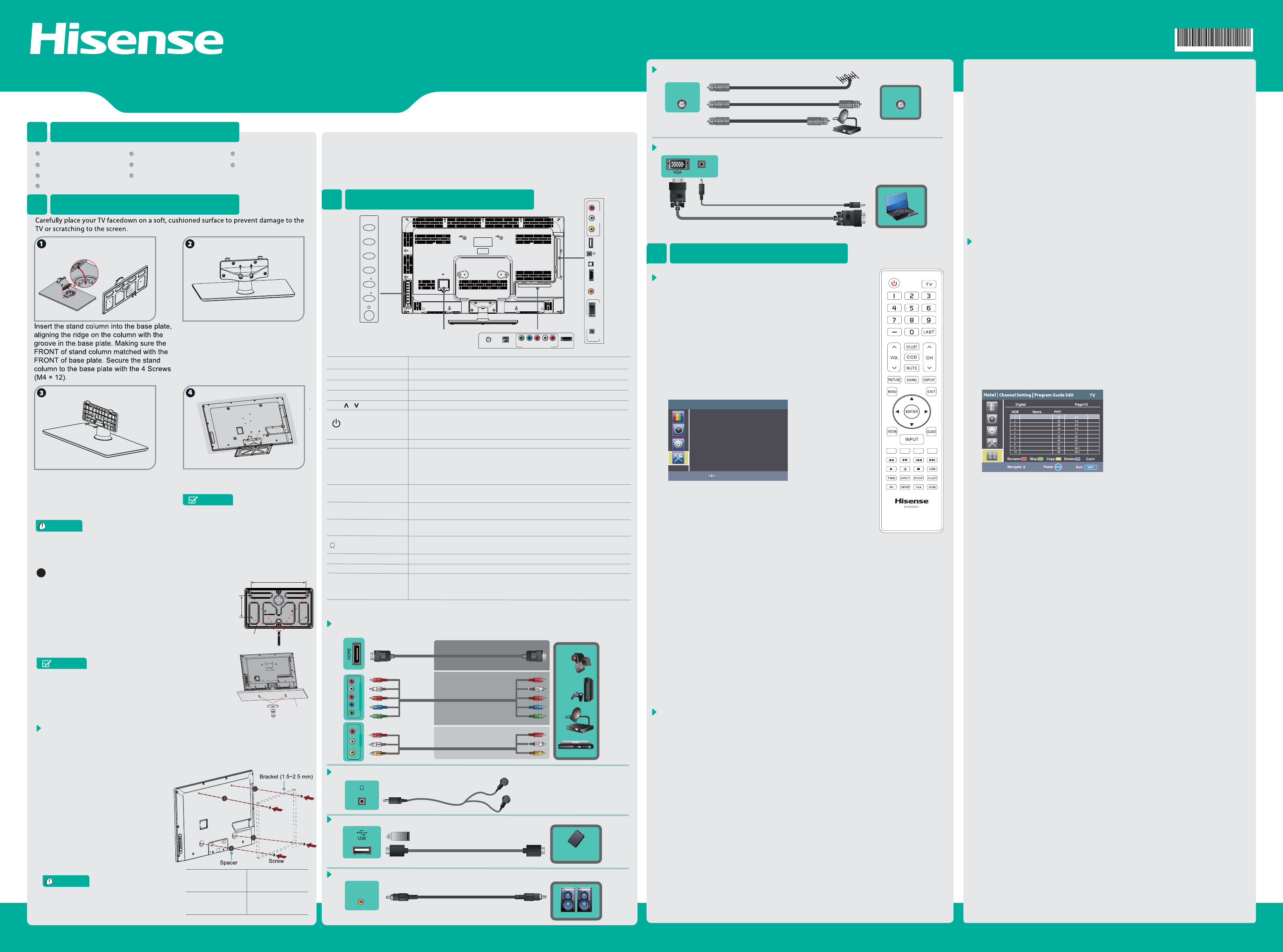
VGA & PC AUDIO IN Connect a VGA cable and an audio cable from the PC.
QUICK SETUP GUIDE
Hotel Settings
No further notice for any spec change and update etc.
User Manual Quick Setup Guide Important information
Remote Control Screw (ST4 × 14) ×2
Screw (M5 × 12) × 4
For 39” 42”: Spacer × 4 Screw (M6 × 30) × 4
Batteries: AAA × 2
Screw (M4 × 12) × 6
Locate the TV and Stand in the desired position on
the table or desk.
For a 32” TV, mark a rectangle12”(304mm)x 4.7”
(120mm).
Drill a 0.25”(~6mm) diameter hole at each corner of the
rectangle.
Using M5 bolts, attached the TV and Stand to the table or
desk.Use a bolt length equal to the thickness of the table
or desk plus 0.3~0.4” (8~10mm). E.g. if table thickness =
0.6” (15mm); use an M5×25 bolt.
The Picture is Only for Reference.
NOTE
table
4-Screws
4.7inch
(120mm)
stand
Included with the TV Stand are four (4) double-end studs.
One end is M5 and attaches to the TV Stand. The other
end is M6 and is suitable for mounting the TV Stand on a
table or desk up to 1” (25mm) thick. Also included are four
(4) M6 washers and four (4) M6 nuts for attaching the TV
Stand to the table or desk using the double-end studs.
AC power cord
MENU Display the on-screen menu to setup your TV’s features.
INPUT Select the different input signal sources.
Adjust the volume.
CH /
VOL +/-
Select the channel.
(Power button)
Turn on the TV or put the TV in standby mode.
Caution: The TV continues to receive power even in standby mode.
Unplug the power cord to disconnect power.
Item Description
ANT/CABLE Connect an antenna or cable TV to this jack.
HDMI
HDMI (High-Definition Multimedia Interface) provides an
uncompressed, all digital audio/video interface between this TV and
any HDMI-device, such as a set-top box, Blu-ray disc player, or A/V
receiver.
COMPONENT IN Connect to a DVD player, Digital Set-Top-Box, or other A/V devices
with component (YPBPR) video and audio output jacks.
AV IN Connect to the composite video and audio (L/R) output jacks on
external video devices.
VGA
PC/DVI AUDIO IN Connect to a PC or other devices with a VGA or DVI interface.
/AUDIO OUT Connect headphone or analog sound system using RCA Y-cable
(1/8"-stereo mini to L/R phono-not provided).
DIGITAL OUTPUT Connect an audio amplifier to this jack.
USB
RJ12
Port for Digital Media Player and for software update.
Connect a RJ-12 Cable to this jack, then to an external control device
(such as a computer or A/V control system), to control the TV functions
externally.
Check the jacks' for position and type before making any connections. Loose connections can
result in image or color problems. Make sure that all connections are tight and secure.
TV SETUP
5
Connect an outdoor VHF/UHF antenna.
ANT
OR
OR
HDMI / COMP / AV Connect an HDMI cable or Comp/AV Adapter from an external A/V
equipment.
AV
Component
L
R
BEST (HDMI)
BETTER
(COMP)
GOOD
(AV)
Y
Pb
Pr
L
R
Video Video
L
R
Y
Pb
Pr
L
R
1.Turn on the TV using the Power key on the remote control
(top/left).
2..Press the “MENU” key on the remote control.
3.Press the “DOWN” arrow key three times to highlight the
Installation icon.
4.Press the “ENTER” key to select the Installation submenu.
5.Use the “UP” or “DOWN” arrow keys to navigate in the
Installation submenu:
(1).Language
(2).Channels
(3).Time
(4).Source Labels
(5).Reset AV settings
6.Select “Channels” and press the “ENTER” key on the remote
control.
7.Select “Installation Mode/Tuner source” and press the “ENTER”
key on the remote control.
(1).Select appropriate connection: “Antenna” or “Cable” and
press the “ENTER” key on the remote control.
Installation TV
Language English
Channels >>>
Time >>>
Source Labels >>>
Reset AV settings Start now
Move: Enter: OK Exit: EXIT
TV Setup.
(1).Connect target TV to AC Power.
(2).Plug pre-loaded USB drive (prepared in Step-5a) into USB port on the side
of the target TV.
(3).Turn target TV on using the Power key on the remote control.
(4).TV will display “USB connection, are you sure you want to switch to USB?”
(5).Press “MENU’.
(6).Select “SOUND” sub-menu and press “ENTER”.
(7).Select “BALANCE” and press “ENTER”.
(8).Use the Arrow keys on the remote control to adjust balance to zero then
enter access code “5 4 8” using the numeric keys on the remote control to
open the Hotel menu. Press the “ENTER” key on the remote control.
(9).Select “CLONE” and press the “ENTER” key on the remote control.
(10).Select “Write In” and press the “ENTER” key on the remote control.
(11).TV will display “Cloning Function – Write In”.Select “YES” and press the
“ENTER” key on the remote control.
(12).TV will display “download success, system rebooting” and automatically
exit the Hotel menu.
(13).The TV settings have been transferred to the target TV.
(14).Turn target TV off using the Power key on the remote control.
(15).Remove the USB drive from the target TV.
1.Turn TV on using the Power key on the remote control.
2.Press “MENU’.
3.Select “SOUND” sub-menu and press “ENTER”.
4.Select “BALANCE” and press “ENTER”.
5.Use the Arrow keys on the remote control to adjust balance to zero then enter
access code “5 4 8” using the numeric keys on the remote control to open the
Hotel menu. Press the “ENTER” key on the remote control.
6.Select “Channel Setting” and press the “ENTER” key on the remote control.
7.Select “Tuner Source” and press the “ENTER” key on the remote control.
(1).Select appropriate connection: “Antenna” or “Cable” and press the
“ENTER” key on the remote control.
(2).Select “Auto Scan” and press the “ENTER” key on the remote control.
Start now is displayed; press the “ENTER” key on the remote control.
(3).When the Auto Scan is complete, select “FINISH” and press the “ENTER”
key on the remote control.
8.To customize the channel map, select “Program Guide Edit” and press the
“ENTER” key on the remote control.
c.Copy the highlighted channel entry= YELLOW.
d.Delete the highlighted channel entry= BLUE.
(3).In addition the “RIGHT” arrow key on the remote control modifies the
highlighted channel entry’s position in the channel map.
9.Rename (RED remote control key)
(1).Use the remote control to navigate the virtual keyboard and enter the
desired channel name.
(2). Select “DONE” and press the “ENTER” key on the remote control.
10.Skip (GREEN remote control key)
(1).Press the “GREEN” key on the remote control to toggle the channel entry
skip setting (on and off).
11.Copy (YELLOW remote control key)
(1).Press the “YELLOW” key on the remote control to copy the highlighted
entry.
(2).Use the “UP” or “DOWN” arrow keys on the remote control to move the
cursor to the desired channel map position and press the “ENTER” key on the
remote control to insert a copy of the highlighted entry into the channel map.
12.Delete (BLUE remote control key)
(1).Press the “BLUE” key on the remote control to remove the highlighted
entry from the channel map.
13.Insert (“RIGHT” arrow remote control key) may be used to adjust the location
of channels in the channel map.
(1).Notes:
a.When the “CH UP” and “CH DN” keys are pressed on the remote control, the
channels are tuned in the order they are saved in the channel map.
b.The auto scan function searches for analog channels first the digital
channels so the preset order will start with analog channels from position
number 1 and follow with digital channels. A typical use of the Insert function
would be to relocate the digital channels to start from position number 1 and
follow with the analog channels or to locate a custom hotel greeting or
information channel at the top of the channel map.
(2).Press the “RIGHT” arrow remote control key to select the highlighted entry.
(3).Use the “UP” or “DOWN” arrow keys on the remote control to move the
cursor to the desired channel map position and press the “ENTER” key on the
remote control. The channel will be moved to the selected position and
inserted into the channel map.
a.For example, to move the channel in position 8 to position 1.
(a).Highlight the channel in position 8 and press the “RIGHT” arrow key on the
remote control.
(b).Use the “UP” arrow key on the remote control to move the cursor to
position 1 and press the “ENTER” key on the remote control.
(c).The channel that was in position 8 will now be in position 1 and any
channels affected by the insertion will automatically be shifted accordingly
inthe channel map.
14.Press the “EXIT” key on the remote control when finished making changes to
the channel map. The hotel menu will automatically close.
Channel Setting and Custom Channel Map.
Connect Headphone for audio out of the TV.
HEADPHONE
(2).Select “Auto Program/Auto Scan” and press the “ENTER” key on the remote
control.
(3).When the Auto Programming is complete, press the “EXIT” key on the remote
control.
8.To set up the tuner with a custom channel map, see Step-6.
For Pro:Idiom™ Standard & High Definition Systems with custom channel remap-
ping:
(1).Turn TV on using the Power key on the remote control.
(2).Press “MENU’.
(3).Select “SOUND” sub-menu and press “ENTER”.
(4).Select “BALANCE” and press “ENTER”.
(5).Use the Arrow keys on the remote control to adjust balance to zero then enter
access code “5 4 8” using the numeric keys on the remote control to open the Hotel
menu. Press the “ENTER” key on the remote control
(6).Select “SSID Setting” (scroll down below Clone option) and press the “ENTER”
key on the remote control.
(7).Select “Set SSID” and press the “ENTER” key on the remote control.
(8).TV will display “Set SSID” menu. Use the remote control to navigate the virtual
keyboard and enter the SSID.
(9).Select “DONE” and press the “ENTER” key on the remote control.
(10).To set up the tuner with a custom channel map, see Step-6.
(1).Use the “UP” or “DOWN” arrow keys
and the “ENTER” key on the remote
control to highlight the channel entry to
modify.
(2).On the remote control there are four
color coded keys to modify the
highlighted channel entry:
a.Rename the highlighted channel entry=
RED.
b.Skip the highlighted channel entry=
GREEN.
Wall-mount hole
pattern VESA
(mm)
100×100 (32”)
200×200 (39” 42”)
Wall-mount screw
size (mm)
M4 (32”)
M6 (39” 42”)
Connect a digital audio device to this jack.
DIGITAL AUDIO OUT
Connect a USB device for browsing photos and music.
USB
1.Turn on the TV using the Power key on the remote control (top/left).
2.Press the “MENU” key on the remote control.
To simplify multiple TV set installation, after configuring a TV all its settings may
be cloned (copied) to additional TV units via USB; to begin:
(1).Connect a fully configured TV to AC Power.
(2).Plug a USB drive into USB port on the side of the TV.
(3).Turn TV on using the Power key on the remote control.
(4).TV will display “USB connection, are you sure you want to switch to USB?”
(5).Press “MENU’.
(6).Select “SOUND” sub-menu and press “ENTER”.
(7).Select “BALANCE” and press “ENTER”.
(8).Use the Arrow keys on the remote control to adjust balance to zero then
enter access code “5 4 8” using the numeric keys on the remote control to
open the Hotel menu. Press the “ENTER” key on the remote control.
(9).Select “CLONE” and press the “ENTER” key on the remote control.
(10).Select “Read Out” and press the “ENTER” key on the remote control.
(11).TV will display “Cloning Function – Read Out”. Select “YES” and press
the “ENTER” key on the remote control.
(12).TV will display “Please wait…” then “Upload Success” and automatically
exit the Hotel menu.
(13).The TV settings have been saved to the USB drive.
Clone setting to additional TVs. Note: the target TV does not need input
source(s) connected during the cloning process.
Duplicating Setup for multiple TV installations.
PC AUDIO IN
;;;;;
AUDIO OUT
12inch(304mm)
Secure the stand cover to the stand
column vertically with the 2 screws
(M4×12) provided.
Secure the stand cover to the stand
column horizontally with the 2 screws
(ST4×14) provided.
Secure the stand cover to the TV with
the 4 screws (M5×12) provided.
NOTES
INPUT
MENU
CH
CH
VOL
VOL
Mobile Hard Disk
VHF/UHF Antenna
ANT OUT
VIDEO L R
AV IN YPBPRL R
COMPONENT IN
DIGITAL
AUDIO OUT
ANT/CABLE SERVICE YPBPRL R HDMI 1
COMPONENT IN
PC AUDIO IN VGA
PC IN
HDMI 2 AUDIO
OUT
RJ12 VIDEO LR
AV IN
USB
DIGITAL
OUTPUT
Note: Only for LHD39A300MH &
42A300MH,32K366MH dose not need
spacers.
ANT/CABLE
Channel No. Skip
Add
Add
Add
Add
Add
Add
Add
Add
Add
Add