Hitachi Garage Door Opener Ru 1200Jy Vr Users Manual
RU- 1200JY VR to the manual fb534cc2-0b91-4972-b6e8-9e45d6c88d28
2015-01-24
: Hitachi Hitachi-Garage-Door-Opener-Ru-1200Jy-Vr-Users-Manual-313348 hitachi-garage-door-opener-ru-1200jy-vr-users-manual-313348 hitachi pdf
Open the PDF directly: View PDF ![]() .
.
Page Count: 45
㻌
HD COLOR CAMERA SYSTEM
REMOTE
㻌
CONTROL UNIT
RU-1200JY/VR
OPERATING INSTRUCTIONS
Please read these operating instructions carefully for proper operation,
and keep them for future reference.
㻌
㻌
㻌
㻌
㻌
㻌
㻌
㻌
㻌
㻌
㻌
㻌
㻌
㻌
㻌
㻌
㻌
㻌
㻌
㻌
㻌
㻌
㻌
㻌
㻌
㻌
㻌
㻌
㻌
㻌
㻌
㻌
㻌
㻌
㻌
Note: The model and serial numbers of your product are important for you to keep for your
convenience and protection. These numbers appear on the nameplate located on bottom of the
product. Please record these numbers in the spaces provided below, and retain this manual for
future reference.
Model No. Serial No.

Contents
Outline and features .......................................................................................................................................... 1
Facility names and functions ............................................................................................................................. 2
Function menu ................................................................................................................................................... 5
Operation procedure .......................................................................................................................................... 10
Service information ............................................................................................................................................ 32
Specifications ..................................................................................................................................................... 33

A
SAFETY INSTRUCTIONS
Carefully read all safety messages in this manual and safety Instructions on your equipment.
Follow recommended precautions and safe operating practices.
SAFETY ALERT SYMBOL
This is the “Safety Alert Symbol.” This symbol is used to call your attention to items or operations
that could be dangerous to you or other persons using this equipment. Read these messages and
follow these instructions carefully.
It is essential that you read the instructions and safety regulations before you attempt to assemble or use this
equipment.
The definitions of signal words are as follows:
WARNING: Personal danger
Warning notes indicate any condition or practice, which if not strictly observed, could result
in personal injury or possible death.
CAUTION: Possible damage to equipment
Caution notes indicate any condition or practice, which if not strictly observed or remedied,
could result in damage or destruction of the equipment.
NOTE: Notes indicate an area or subject of special merit, emphasizing either the productcs
capabilities or common errors in operation or maintenance.
WARNING: TO REDUCE THE RISK OF FIRE OR ELECTRIC SHOCK, DO NOT EXPOSE THIS COLOR
CAMERA TO RAIN OR MOISTURE.
AVERTISSEMENT
Afin d’éviter tout risque d’incendie ou d’électrocution, ne pas exposer l’appareil á la pluie ou á l’humidité.
Afin d’écarter tout risque d’électrocution, garder le coffret fermé.
Ne confier l’entretien de l’appareil qu á un personnel qualifié.
VORSICHT
Um Feuergefahr und die Gefahr eines eiektrischen Schiages zu vermeiden, darf das Gerät weder Regen
noch Feuchtigkeit ausgesetzt werden.
Um einen elektrischen Schiag zu vermeiden, darf das Gehäuse richt geöffnet werden.
Überiassen Sie Wartungsarbeiten stets nur einem Fachmann.
WARNING
CAUTION
NOTE
!
!
!
!

B
IMPORTANT SAFETY INSTRUCTIONS
1. Read Instructions
All the safety and operating instructions should be read before the product is operated.
2. Retain Instructions
The safety and operating instructions should be retained for future reference.
3. Heed Warnings
All warnings on the product and the operating instructions should be adhered to.
4. Follow Instructions
All operating and use instructions should be followed.
5. Cleaning
Unplug this product from the wall outlet before cleaning. Do not use liquid cleaners or aerosol cleaners.
Use a damp cloth for cleaning.
6. Attachments
Do not use attachments not recommended by the product manufacturer as they may cause hazards.
7. Water and Moisture
Do not use this product near water - for example, near a bath tub, wash bowl, kitchen sink, or laundry
tub; in a wet basement; or near a swimming pool; and the like.
8. Accessories
Do not place this product on an unstable cart, stand, tripod, bracket, or table. The product may fall,
causing serious injury to a child or adult, and serious damage to the product. Use only with a cart,
stand, tripod, bracket, or table recommended by the manufacturer, or sold with the product. Any
mounting of the product should follow the manufacturer's instructions, and should use a mounting
accessory recommended by the manufacturer.
9. Moving
A product and cart combination should be moved with care.
Quick stops, excessive force, and uneven surfaces may cause the product and cart combination to
overturn.
10. Ventilation
Slots and openings in the cabinet are provided for ventilation and to ensure reliable operation of the
product and to protect it from overheating, and these openings must not be blocked or covered.
The openings should never be blocked by placing the product on a bed, sofa, rug, or other similar surface.
This product should not be placed in a built-in installation such as a bookcase or rack unless proper
ventilation is provided or the manufacturer's instructions have been adhered to.
11. Power Sources
This product should be operated only from the type of power source indicated on the marking label. If
company. For products intended to operate from battery power, or other sources, refer to the operating
instructions.
12. Grounding or Polarization
This product is equipped with a three-wire grounding-type plug a plug having a third (grounding) pin.
This plug will only fit into a grounding-type power outlet. This is a safety feature. If you are unable to
insert the plug into the outlet, contact your electrician to replace your obsolete outlet. Do not defeat the
safety purpose of the grounding-type plug.
13. Power-Cord Protection
Power-supply cords should be routed to that they are not likely to be walked on or pinched by items
placed upon or against them, paying particular attention to cords at plug, convenience receptacles, and
the point where they exit from the product.
C
14. Lightning
For added protection for this product during a lightning storm, or when it is left unattended and unused
for long periods of time, unplug it from the wall outlet. This will prevent damage to the product due to
lightning and power-line surges.
15. Overloading
Do not overload wall outlets, extension cords or integral convenience receptacles as this can result in a
risk of fire or electric shock.
16. Object and Liquid Entry
Never push objects of any kind into this product through openings as they may touch dangerous voltage
points or short-out parts that could result in a fire or electric shock. Never spill liquid of any kind on
the product.
17. Inflammable and Explosive Substance
Avoid using this product where there are gases, and also where there are inflammable and explosive
substances in the immediate vicinity.
18. Heavy Shock or Vibration
When carrying this product around, do not subject the product to heavy shock or vibration.
19. Servicing
Do not attempt to service this product yourself as opening or removing covers may expose you to
dangerous voltage or other hazards. Refer all servicing to qualified service personnel.
20. Damage Requiring Service
Unplug this product from the wall outlet and refer servicing to qualified service personnel under the
following conditions:
a. When the power-supply cord or plug is damaged.
b. if liquid has been spilled, or objects have fallen into the product.
c. If the product has been exposed to rain or water.
d. If the product does not operate normally by following the operating instructions. Adjust only
those controls that are covered by the operating instructions as an improper adjustment of other controls
may result in damage and will often require extensive work by a qualified technician to restore the
product to its normal operation.
e. If the product has been dropped or damaged in any way.
f. When the product exhibits a distinct change in performance-this indicates a need for service.
21. Replacement Parts
When replacement parts are required, be sure the service technician has used replacement parts
specified by the manufacturer or have the same characteristics as the original part.
Unauthorized substitutions may result in fire, electric shock, or other hazards.
22. Safety Check
Upon completion of any service or repairs to this product, ask the service technician to perform safety
checks to determine that the product is in proper operating condition.
23. Wall or Ceiling Mounting
The product should be mounted to a wall or ceiling only as recommended by the manufacturer.
24. Heat
The product should be situated away from heat sources such as radiators, heat registers, stoves, or other
products (including amplifiers) that produce heat.

D
WICHTIGE SICHERHEITSANWEISUNGEN
1. Alle Anweisungen lesen.
Vor Betrieb des Erzeugnisses sollten alle Sicherheits-und Bedienungsanleitungen gelesen werden.
2. Die Anweisungen aufbewahren.
Die Sicherheits-und Bedienungsanleitungen sollten fünftigen Bezug aufbewahrt werden.
3. Warnungen beachten.
Die Warnungen auf dem Erzeugnis und in den Bedienungsanleitungen solten beachtet werden.
4. Anweisungen befolgen.
Alle Bedienungsanleitung-und
Verwendungsanweisungen sollten befolgt werden.
5. Reinigung
Den Stecker des Geräts vor Reinigung aus der Steckdose ziehen. Keine flüssigen Reinigungsmittel
oder Aerosolreiniger verwenden. Zum Reinigen einen feuchten Lappen verwenden.
6. Zubehör
Nur vom-Hersteller des Erzeugnisses empfohlenes Zubehör verwenden, da es sonst zu Störungen
kommen kann.
7. Wasser und Feuchtigkeit
Dieses Erzeugnis nicht in der Nähe von Wasser verwenden - z.B, in der Nähe einer Badewanne, eines
Waschbeckens, einer Küchenspüle, eines Waschzubers, in einem nassen Keller, in der Nähe eines
Schwimmbeckens usw.
8. Aufstellung
Das Erzeugnis nicht auf einen unstabilen Wagen, Stand, Dreifuß, Träger oder Tisch stellen.
Das Erzeugnis kann sonst herunterfallen und ein kind oder einen Erwachsenen schwer verietzen.
Außerdem kann das Gerät schwer beschädigt werden. Nur mit einem Wagen, Stand, Dreifuß, Träger
oder Tisch verwenden, der vom Hersteller empfohlen oder mit dem Erzeugnis verkauft worden ist. Für
jegliche Anbringung sollten die Anweisungen des Herstellers befolgt werden, und das vom Hersteller
empfohlene Anbringungszubehör sollte verwendet werden.
9. Eine Kombination von Erzeugnis und Wagen sollte vorsichtig bewegt werden.
Schneller Halt, übermäßige Krafteinwirkung und unebene Oberflächen können Umkippen der
kombination von Erzeugnis und Wagen verursachen.
10. Ventilation
Schlitze und Öffnungen im Gehäuse dienen der Ventilation. Sie sind für zuverlässigen Betrieb des
Gerätes und Schutz vor Überhitzung erforderlich und dürfen nicht blockiert oder abgedeckt werden.
Die Öffnungen sollten niemals dadurch blockiert werden, daß, das Gerät auf ein Bett, ein Sofa, einen
Teppich oder eine ähnliche Oberfläche gestellt wird.
Das Gerät sollte nur dann in Einbauinstallierung wie in einem Bücherschrank oder einem Gestell
verwendet werden, wenn angemessene Ventilation vorgesehen ist bzw. Die Anweisungen des
Herstellers befolgt worden sind.
11. Stromversorgung
Dieses Erzeugnis sollte nur an der auf dem Typenschild angegebenen Stromversorgungsart betrieben
werden. Wenn Sie nicht sicher sind, was für eine Stromversorgung Sie haben, so wenden Sie sich bitte
an Ihren Erzeugnishändler oder an das lokale Elektrizitätswerk. Beziehen Sie sich für Batteriebetrieb
oder andere Stromquellen vorgesehene Erzeugnisse bitte auf die Bedienungsanleitungen.
12. Erdung oder Polarisierung
Dieses Erzeugnis ist mit einem Schutzkontaktstecker mit drei Leitern ausgerüstet, mit einem
Erdungskontakt. Dieser Stecker paßt nur in ein schuko-Steckdose. Dies ist eine
Sicherheitsmaßnahme. Wenn Sie den Stecker nicht in die Steckdose stecken können, so wenden Sie
sich bitte an ihren Elektriker, damit er die veraltete Schuts des Schutzkontaktsteckers unwirksam.
13. Netzkabelschutz
Netzkabel sollten so verlegt werden, deß möglichst nicht darauf getreten wird und daß sie nicht
eingeklemmt werden, mit besonderer Beachtung der kabel an Stackern, Verlängerungskabeln und dem
Austritt des Kabels aus dem Erzeugnis.
E
14. Blitzschlag
Für zusätzlichen Schutz des Erzeugnisses während eines Gewitters oder bei Nichtverwendung für lange
Zeit den Stecker aus der Steckdose ziehen. Dies verhütet Beschädigung durch Blitzschlag und
Netzspannungsstöße.
15. Überlastung
Wandsteckdosen, Verlängerungskabel und eingebaute Bequemlickkeitssteckdosen nicht überlasten, da
dies Feuer oder elektrischen Schlag verursachen kann.
16. Eindringen von Fremdkörpern und Flüssigkeit
Niemals Objekte irgendwelcher Art durch die Öffnungen in das Gerät schieben, da diese unter hoher
Spannung stehende Teile berühren oder kurzschließen können, wodurch es zu Feuer oder elektrischem
Schlag kommen kann. Niemals Flüssigkeiten irgendwelcher Art auf das Erzeugnis verschütten.
17. Entflammbare und explosive Substanzen
Vermeiden Sie Verwendung dieses Erzeugnisses an Orten mit Gasen bzw. entflammbaren oder
explosiven Substanzen in der direkten Umgebung.
18. Starke stöße oder Vibrationen
Setzen Sie das Erzeugnis beim Transport nicht starken Stößen oder Vibrationen aus.
19. Wartung
Versuchen Sie nicht, dieses Erzeugnis Selbst zu warten, da Sie sich durch Öffnen bzw. Entfernen von
Abdeckungen hohen Spannungen und sonstigen Gefährdungen ausserzen können.
Beziehen Sie sich für jegliche Wartung auf qualifiziertes Wartungspersonal.
20. Beschädigung, die Wartung erfordert
Ziehen Sie den Stecker dieses Erzeugnisses aus der Steckdose und wenden Sie sich an qualifiziertes
Wartungspersonal, wenn eine der folgenden Bedingungen vorliegt:
a. Wenn das Netzkabel oder der Stecker beschädigt ist.
b. Bei Eindringen von Flüssigkeit oder Fremdkörpern in das Gerät.
c. Wenn das Erzeugnis Regen oder Wasser ausgesetzt worden ist.
d. Wenn das Erzeugnis bei Befolgen der Bedienungsanleitungen nicht normal funktioniert.
Nur die Regelelemente verstellen, die in den Bedienungsanleitungen behandelt werden, da
unangemessene Einstellung anderer Regelelemente Beschädigung verursachen kann und oft
beträchtliche Arbeit durch einen qualifizierten Techniker erfordert, um das Erzeugnis wieder, zu
normalem Betrieb zurückzubringen.
e. Wenn das Erzeugnis fallen gelassen oder beschädigt worden ist.
f. Wenn das Erzeugnis eine klare Änderung in der Leistung zeigt-dies weist darauf hin, daß
Wartung erforderlich ist.
21. Ersatzteile
Wenn Ersatzteile erforderlich sind, darauf achten, daß der Wartungstechniker nur die vom Hersteller
festgelegten Ersatzteile oder Teile mit den gleichen Charakteristiken wie die ursprünglichen Teile
verwendet. Unautorisierte Ersatzteile können Feuer, elektrischen Schlag oder sonstige Gefährdungen
verursachen.
22. Sicherheitsprüfung
Bitten Sie den Wartungstechniker nach der Vollendung von Wartung oder Reparaturarbeiten an diesem
Erzeugnis um die Durchführung von Sicherheitsprüfungen, um zu bestimmen, daß das Erzeugnis im
angemissenen Betriebszustand ist.
23. Anbringung an der Wand oder an der Decke
Das Erzeugnis sollte nur entsprechend den Empfehlungen des Herstellers an einer Wand oder an der
Decke angebracht werden.
24. Wärme
Das Erzeugnis sollte fern von Wärmequellen wie Radiatoren, Heizwiderständen, Öfen und anderen
Wärme erzeugenden Erzeugnissen (einschließlich Verstärkern) aufgestellt werden.

F
MISES EN GARDE IMPORTANTES
1. Lire les instructions
Lire toutes les instructions de sécurité et de fonctionnement avant de faire fonctionner l’appareil.
2. Conserver ces instructions
Conserver les instructions de sécurité et de fonctionnement á des fins de référence ultérieure.
3. Tenir compte des avertissements
Tous les avertissements qui figurent sur l’appareil et dans le mode d’emploi devront être respectés.
4. Observer les instructions
Observer toutes les instructions de fonctionnement et d’utilisation.
5. Nettoyage
Avant de procéder au nettoyage, débrancher l’appareil de la prise secteur. Ne pas utiliser de produits
de nettoyage liquides ou en aérosol.
Nettoyer l’appareil avec un chiffon humide.
6. Fixations
Ne pas utiliser de fixations non recommandées par le fabricant de l’appareil car elles pourraient être
source de danger.
7. Eau et humidité
Ne pas utiliser l’appareil á proximité d’eau-par exemple prés d’une baignoire, d’un lavabo, d’un évier ou
d’un bac á lessive, dans un sous-sol humide, ou prés d’une piscine, etc.
8. Accessoires
Ne pas placer l’appareil sur un chariot, un socle, un pied, un support ou one table instables L’appareil
pourrait tomber, blessant griévement des enfants ou des adultes, et étant sérieusement endommagé.
Utiliser exclusivement le chariot, le socle, le pied, le support ou la table recommandés par le fabricant,
ou vendus avec l’appareil. Pour tout montage de l’appareil, respecter les instructions du fabricant, et
utiliser á cette fin l’accessoire de montage recommandé par le fabricant.
9. L’appareil monté sur son chariot devra être déplacé avec précaution.
Des arrêts brusques, une force excessive et des surfaces irréguliéres pourraient provoquer le
renversement de l’ensemble appareil-chariot.
10. Ventilation
Les fentes et les ouvertures du coffret sont prévues pour la ventilation ainsi que pour garantir un
fonctionnement en toute sécurité de l’appareil et le protéger de toute surchauffe, et ces ouvertures ne
devront donc être ni obstruées ni recouvertes. Ne jamais obstruer les ouvertures en placant l’appareil
sur un lit, un sofa, un tapis ou toute surface similaire. Ne jamais placer l’appareil dans un support
confiné, par exemple une bibliothéque ou une é tagé re, sans ventilation suffisante ou sans repecter les
instructions du fabricant.
11. Sources d’allmentation
L’appareil devra être alimenté exclusivement sur le type d’alimentation indiqué sur l’étiquette
signalétique. Sil’on n’est pas sûr du type d’alimentatio du local, consulter le revendeur de l’appareil ou
la compagnie d’électricité locale. Pour les appareils qui fonctionnent sur batterie ou sur d’autres
sources, voir le mode d’emploi.
12. Mise á la terre ou polarisation
L’appareil est doté d’une fiche trifilaire avec mise á la terre, dont la troisiéme broche assure la mise á la
terre. Cette fiche ne rentrera que dans les prises trifilaires de mise á la terre. Ceci est une mesure de
sécurité. Si la fiche ne rentre pas dans la prise, faire remplacer la prise désuéte par un électricien.
Ne pas rendre vaine la measure de sécurité assurée par cette prise avec mise á la terre.
13. Protection du cordon d’alimentation
Acheminer les cordons d’alimentation de facon qu’on ne risque pas de marcher dessus ou de les coincer
sous un objet placé dessus ou contre eux.
Faire particuliérement attention aux fiches des cordons, á la proximité des prises, et á l’endroit oú ils
ressortent de l’appareil.
G
14. Foudre
Pour renforcer la protection de l’appareil pendant un orage, ou si l’on s’en éloigne ou qu’on reste
longtemps sans l’utiliser, le débrancher de la source d’alimentation. Ceci permettra d’éviter tout
dommage de l’appareil dú á la foudre et aux surtensions de ligne.
15. Surcharge
Ne pas surcharger les prises, rallonges et prises multiples car cela pourrait entraîner un risque de feu ou
de choc électrique.
16. Pénétration d’objets et de liquides
Ne jamais enfoncer d’objets d’aucune sorte dans les ouvertures de l’appareil car ils pourraient toucher
des points de tension dangereuse ou court-circuiter des piéces, ce qui pourrait provoquer un feu ou un
choc électrique. Ne jamais renverser de liquide d’aucune sorte sur l’appareil.
17. Substances inflammabes et explosives
Eviter d’utiliser l’appareil en présence de gaz, ainsi qu’á proximité immédiate de substances
inflammables et explosives.
18. Chocs ou vibrations violents
Lorsqu’on transporte l’appareil, ne pas le soumettre á des chocs ou des vibrations violents.
19. Réparations
Ne pas tenter de réparer l’aapareil soi-même car le fait d’ouvrir ou de retirer les caches risque d’exposer
l’utilisateur á des tensions dangereuses notamment. Confier toute réparation á un personnel qualifié.
20. Dommages nécessitant réparations
Débrancher l’appareil de la source d’alimentation et confier les réparations á un personnel qualifié dans
les cas suivants:
a. Lorsque le cordon d’alimentation ou sa fiche sont endommagés
b. Si du liquide s’est renversé sur l’appareil ou que des objets sont tombés dedans
c. Si l’appareil a été exposé á la pluie ou á l’eau.
d. Si l’appareil ne fonctionne pas normalement lorsqu’on observe les instructions d’utilisation.
Ne régler que les commandes couvertes par le mode d’emploi ; en effet, un réglage incorrect des autres
commandes pourrait entrainer des dommages et nécessiteront souvent des travaux de réparation
coûteux par un technicien qualifié pour remettre l’appareil en état de marche.
e. Si l’appareil est tombé ou qu’il a été endommagé.
f. Si l’appareil affiche une nette modification de ses performances, cela signifie qu’il a besoin d’être
réparé.
21. Piéces de rechange
Si l’on a besoin de piéces de rechange, veiller á ce que le technicien de réparation utilise exclusivement
les piéces de rechange spécifiées par le fabricant ou des piéces ayant les mêmes caractéristiques que les
piéces d’origine. Les piéces de rechange non autorisées risquent de provoquer un feu, un choc
électrique et autres dangers.
22. Vérificaton de sécurité
Aprés tout travail d’entretien ou de réparation de l’appareil, demander au technicien de réparation
d’effectuer les vérifications de sécurité pour s’assurer que l’appareil est en bon état de marche.
23.Montage au mur ou au plafond
L’appareil ne pourra être monté au mur ou au plafond que de la maniére recommandée par le fabricant.
24. Chaleur
Eloigner l’appareil des sources de chaleur, telles que radiateurs, appareils de chauffage, cuisiniéres, et
de tour produit engendrant de la chaleur (y compris les amplificateurs).

H
IMPORTANT NOTICE
For USA
These products have been tested and found to comply with the limits for a Class A digital device,
pursuant to Part 15 of the FCC Rules. These limits are designed to provide reasonable protection
against harmful interference when the equipment is operated in a commercial environment. This
equipment generates, uses, and can radiate radio frequency energy and, if not installed and used in
accordance with the instruction manual, may cause harmful interference to radio communications.
Operation of this product in a residential area is likely to cause harmful interference in which case the
user will be required to correct the interference at his own expense.
WARNING
Changes or modifications not expressly approved by Hitachi Kokusai Electric responsible for
compliance could void the user’s authority to operate the equipment.
For Canada
This product does not exceed the class A/class B limits for radio noise emissions from digital apparatus
as set out in the radio interference regulations.
Le présent appareil n’émet pas de bruits radioélectriques dépassant les limités applicable aux appareils
numériques de classe A prescrites dans le rVglement sur le brouillage radioélectrique édicter par le
ministére des communications du canada.

1
Outline and features
1᧪General
The remote control unit RU-1200JY/VR is connected to the camera control unit (CCU) for
remote operation of the camera.
The RCU and CCU can be up to 10 meters apart.㻌With the one touch color temperature
control function, the RU-1200JY/VR is ideal not only Studio but also OB van use.
RU-1200JY: Lens iris control, pedestal control and preview switch are assembled with an axis joystick
control knob.
RU-1200VR: Lens iris and pedestal controls are variable register type and located independently. There
is no preview function.
2 Features
The camera can be easily adjusted using the LED optical switch and rotary encoder.
The main control items are:
- Camera power supply on/off
- Auto setup execution
- Data file (SCENE FILE 0 to 8) selection, save
- Manual adjustment using the rotary encoder and knobs
- Various on/off controls
- PIX and WF video output select
2
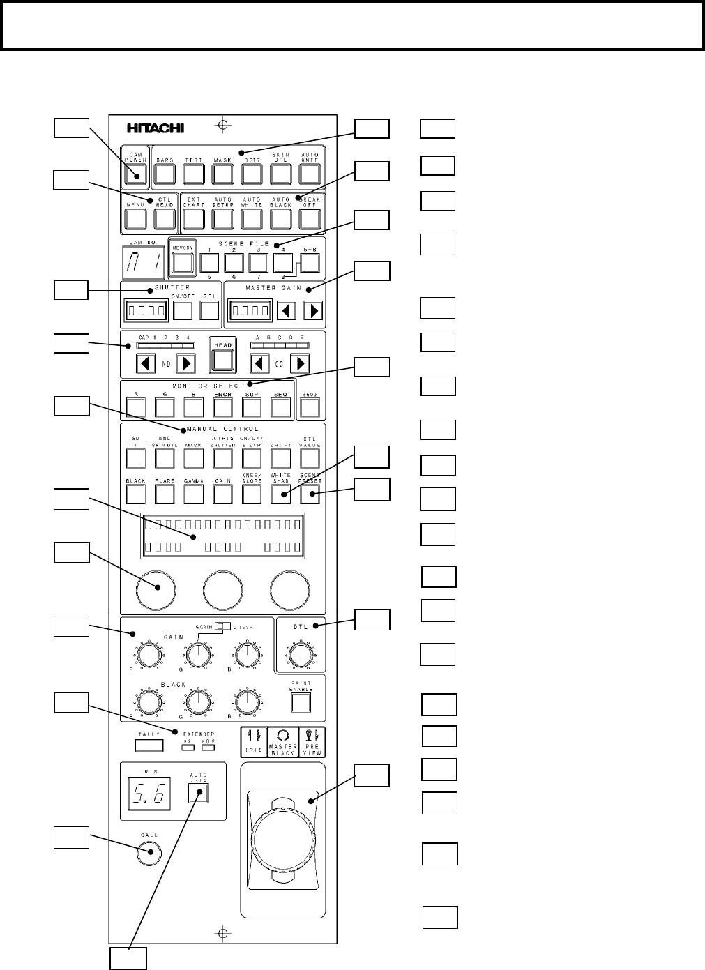
Facility names and functions (Front)
FRONT VIEW (JY type)
A4
A1
A2
A3
A6
A5
A
6
A
1
A
2
A
3
A
4
A
5
A
7
A
8
A
9
A10
A11
A7
A10
A14
A15
A17
A16
A12
A16
Menu switch: Menu is displayed on the pix
monitor with Color bar ON.
Shutter control: In Sequence and Variable
mode
Monitor select
Display section: Manual control item and
each value dis
p
la
y
ed in this LED.
Paint ad
j
ustment
Extender and tally indication LED
Camera power on/off
Auto setup selection switch: External chart,
Auto white & black and Break OFF for stop
the auto set up process
Scene file select and memory
Master gain switch & LED display:
-3dB to +24dBUp
ND/CC filte
r
selection switch
Manual ad
j
ust
Rotary encoder: Refer to operation
procedure
Detail ad
j
ustment
Scene preset switch: Preset to factory
adjustment data and condition.
Iris adjust
Master black adjust
Preview switch
Each t
y
pe on/off control
A9
A8
A11
A12
A17
A18
A14
A15
A18 Call button: Call Camera man and CCU.
The control right is acquired.
A19
A19
A13
A13
White Shad switch:
A20
A20 Auto iris on off switch
3
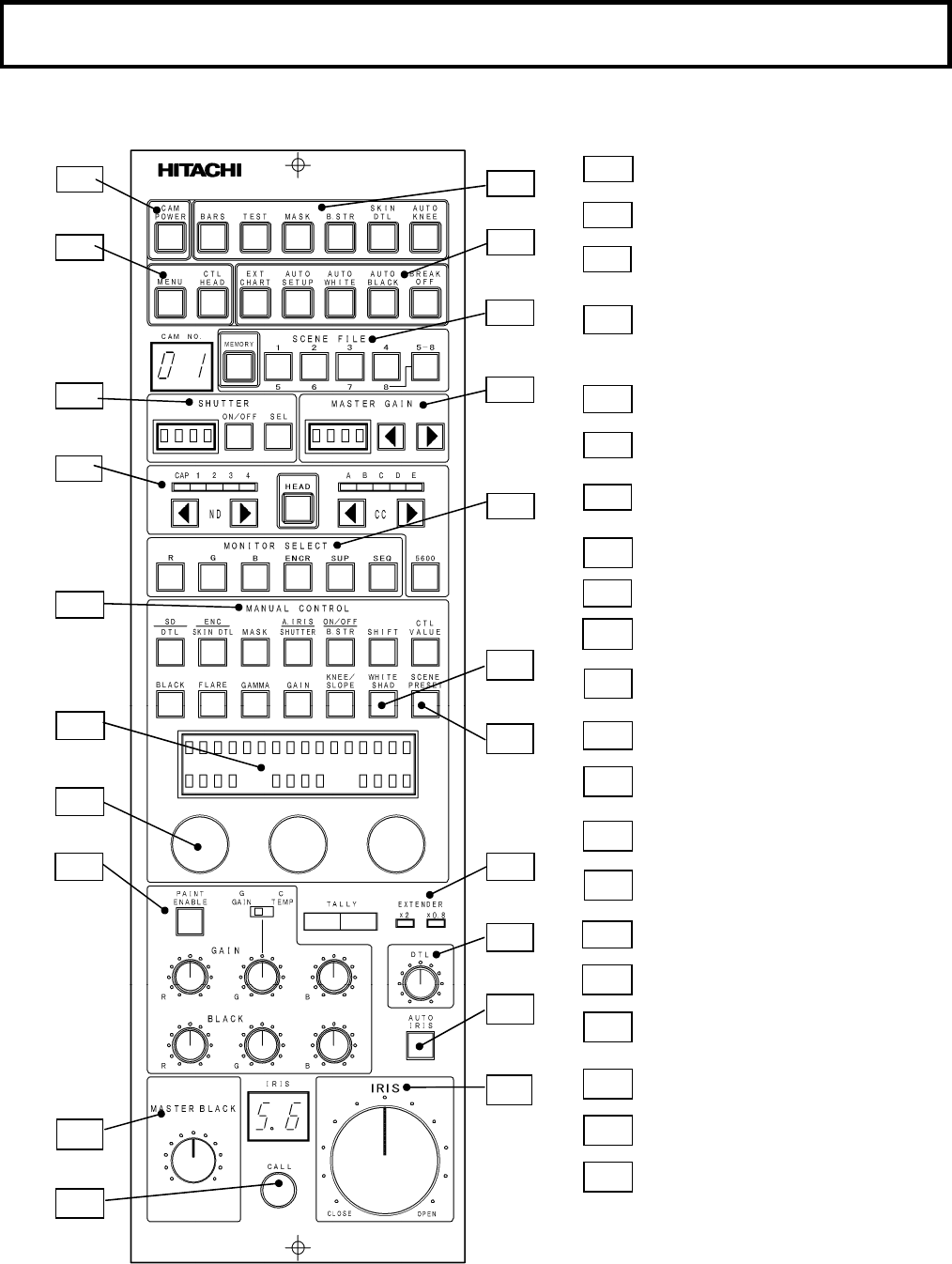
Facility names and functions (Front)
FRONT VIEW (VR type)
A
6
A
1
A
2
A
3
A
4
A
5
A
7
A
8
A
9
A11
A14
A15 A16
A17 A16
Paint ad
j
ustment for Gain and Black.
Extender and tally indication LED
Detail ad
j
ustment
Auto Iris on off
A12
A17
A18
A15
A18
A19
A19
A13
A20
Call button: Call Camera man and CCU.
The control right is acquired.
Master black adjust:
This has center click VR.
A21
Iris adjustment knob
A21
A10
A20
A4
A1
A2
A3
A6
A5
A7
A10
A12
Menu switch: Menu is displayed on the
p
ix monitor with Color bar ON.
Shutter control: In Sequence and Variable
mode
Monitor select
Display section: Manual control item and
each value dis
p
la
y
ed in this LED.
Camera
p
ower on/off
Auto setup selection switch: External chart,
Auto white & black and Break OFF for stop
the auto set up process
Scene file select and memory
Master gain switch & LED display:
-3dB to +24dBUp
ND/CC filte
r
selection switch
Manual ad
j
ust
Rotary encoder: Refer to operation
procedure
Scene preset switch: Preset to factory
adjustment data and condition.
Each t
y
pe on/off control
A9
A8
A11
A14
A13
White Shad switch:
4
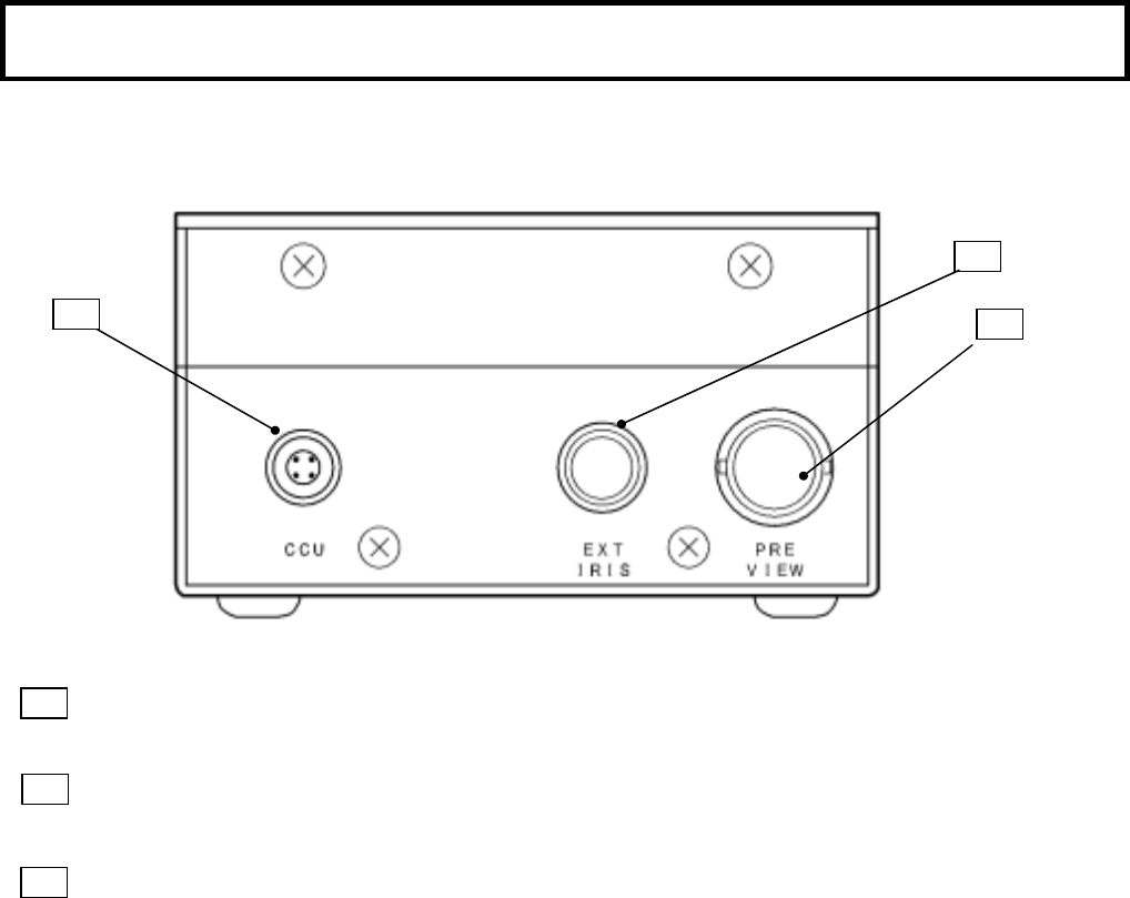
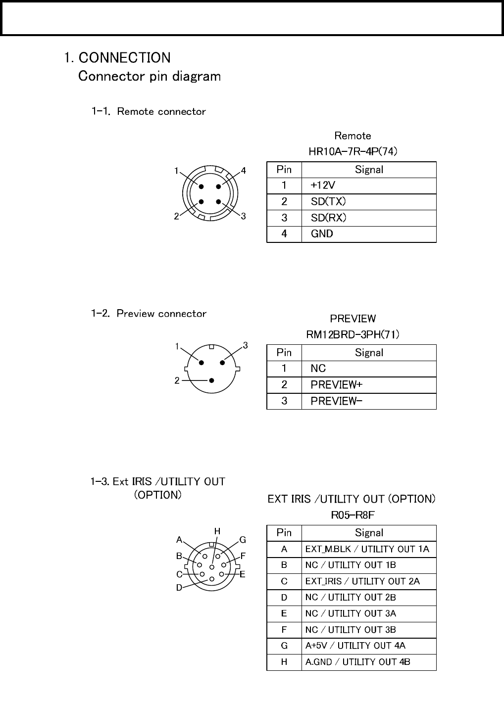
Facility names and functions (Rear)
REAR VIEW
Remote-Input connector
Input and output remote control data between the camera control unit .
.EXT IRIS connector
Connect to the external iris control module (optional)
PRE VIEW Connector (JY type only)
Connect to preview switcher to switch the preview monitor input.
B1
B2
B3
B1
B2
B3
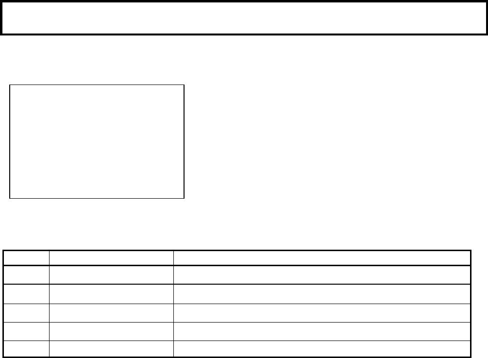
5
Function menu㻌
The camera head is connected with the CCU and the RU/SU as an operational camera system, The CCU
output display TOP MENU on the PIX out monitor as follows. This is for Video operator at the CCU.
PIX MENU: open this menu by pushing the MENU SW in the
RCU.
Item Main Menu Description
1COLOR Change screen to COLOR main menu items display.
2DETAIL Change screen to DETAIL main menu items display.
3MAINTENANCE Change screen to MAINTENANCE main menu items display.
4FILE Change screen to FILE main menu items display.
5SETUP CARD Change screen to FILE main menu items display.
㹒㹍㹎 㹋㹃㹌㹓
ڦ 㹁㹍㹊㹍㹐㸸㸼
㹂㹃㹒㸿㹇㹊 㸸㸼
㹋㸿㹇㹌㹒㹃㹌㸿㹌㹁㹃㸸㸼
㹄㹇㹊㹃㸸㸼
㹑㹃㹒㹓㹎 㹁㸿㹐㹂 㸸㸼
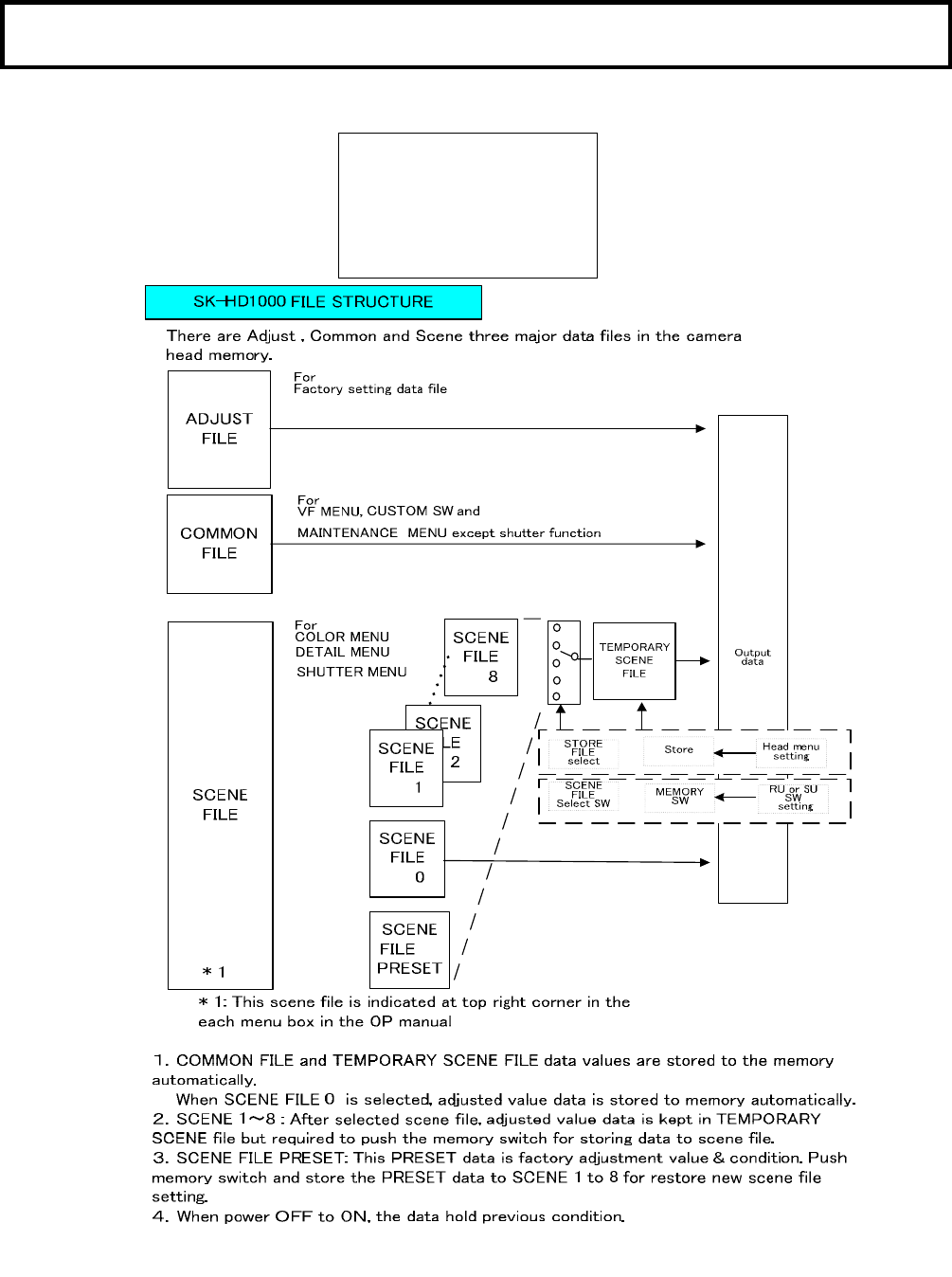
6
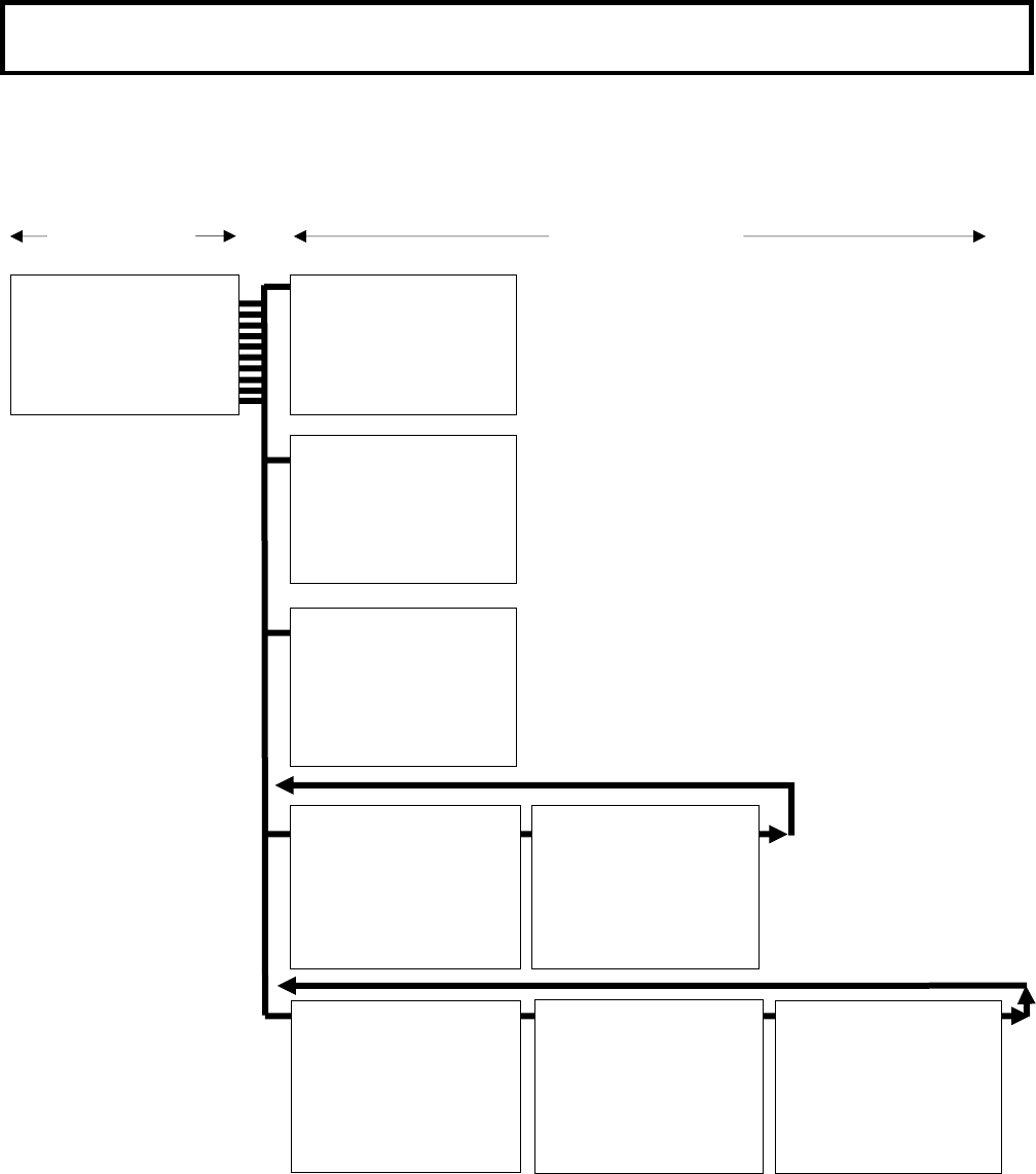
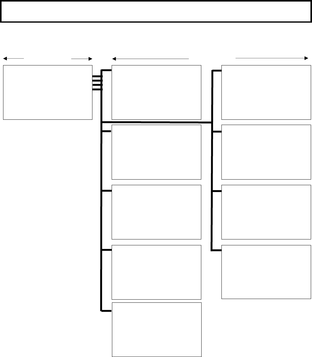
Function menu㻌
1. COLOR menu structure which are displayed in the Pix monitor or are displayed in
the viewfinder with at control head mode.
MAIN MENU SUB-MENU
ڦ㹁㹍㹊㹍㹐 㹋㹃㹌㹓
㹎㸿㹇㹌㹒 㹅㸿㹇㹌 㸸㸼
㹎㸿㹇㹌㹒 㹀㹊㸿㹁㹉㸸㸼
㹅㸿㹋㹋㸿㸸㸼
㹉㹌㹃㹃㸭㹁㹊㹇㹎 㸸㸼㸼
㹋㸿㹑㹉㹇㹌㹅㸸㸼㸼㸼
ڦ㹉㹌㹃㹃㸭㹁㹊㹇㹎 㸯㸸㸼 㹑㹁㹃㹌㹃㸯
㹒㹍㹒㸿㹊 㹉㹌㹃㹃 㸸㸮
㹐 㹉㹌㹃㹃㸸㸮
㹀 㹉㹌㹃㹃㸸㸮
㹒㹍㹒㸿㹊 㹑㹊㹍㹎㹃㸸㸴
㹐 㹑㹊㹍㹎㹃㸸㸮
㹀 㹑㹊㹍㹎㹃㸸㸮
㹉㹌㹃㹃㸸㹍㹌
㸿㹓㹒㹍 㹉㹌㹃㹃 㸸㹍㹄㹄
㹇㹌㹇㹒㹇㸿㹊㹇㹘㹃 㸸
ڦ㹋㸿㹑㹉㹇㹌㹅 㸯㸸㸼 㹑㹁㹃㹌㹃㸯
㹆㹓㹃 㹑㸿㹒㹓㹃㹑㸿㹒
㹐㸸㸮㸮㹁㸸㸮㸮
㹗㸫㹐㸸 㸮 㸮 㹀㸫㹁㸸 㸮 㸮
㹗㸸㸮㸮㹀㸸㸮㸮
㹅㸫㹗㸸 㸮 㸮 㹋㸫㹀㸸 㸮 㸮
㹅㸸㸮㸮㹋㸸㸮㸮
㹁㸫㹅㸸 㸮 㸮 㹐㸫㹋㸸 㸮 㸮
㹋㸿㹑㹉㹇㹌㹅㸸㹍㹄㹄
㹇㹌㹇㹒㹇㸿㹊㹇㹘㹃 㸸
ڦ㹋㸿㹑㹉㹇㹌㹅 㸰㸸㸼 㹑㹁㹃㹌㹃 㸯
㸫㹊㹇㹌㹃㸿㹐㸫
㹐㸫㹅㸸 㸱㸶 㹅㸫㹐㸸 㸯 㹀㸫㹐㸸 㸮
㹐㸫㹀㸸 㸴 㹅㸫㹀㸸㸳㹀㸫㹅㸸 㸯㸯
㹁㹆㹐㹍㹋㸿 㹑㸿㹒 㸸 㸮
㹁㹆㹐㹍㹋㸿 㹑㸿㹒 㸸㹍㹄㹄
㹋㸿㹑㹉㹇㹌㹅㸸㹍㹄㹄
㹇㹌㹇㹒㹇㸿㹊㹇㹘㹃 㸸
ڦ㹋㸿㹑㹉㹇㹌㹅 㸱㸸㸺 㹑㹁㹃㹌㹃 㸯
㸫㹑㹉㹇㹌 㹋㸿㹑㹉㹇㹌㹅㸫
㹑㸬㹋㸿㹑㹉㸬㹑㸿㹒 㸸㸮
㹑㸬㹋㸿㹑㹉㸬㹆㹓㹃 㸸㸮
㹑㹉㹇㹌 㹋㸿㹑㹉 㸸㹍㹄㹄
㹇㹌㹇㹒㹇㸿㹊㹇㹘㹃 㸸
ڦ㹉㹌㹃㹃㸭㹁㹊㹇㹎 㸰㸸㸺 㹑㹁㹃㹌㹃㸯
㹉㹌㹃㹃 㹑㸿㹒㸸㸰㸲
㹉㹌㹃㹃 㹑㸿㹒 㸸㹍㹄㹄
㹕㹆㹇㹒㹃 㹁㹊㹇㹎 㸸㸮
㹕㹆㹇㹒㹃 㹁㹊㹇㹎 㸸 㹍㹌
㹇㹌㹇㹒㹇㸿㹊㹇㹘㹃 㸸
ڦ㹎㸿㹇㹌㹒 㹅㸿㹇㹌 㸸㸺 㹑㹁㹃㹌㹃 㸯
㹐 㹅㸿㹇㹌㸸㸮
㹀 㹅㸿㹇㹌㸸㸮
㹅 㸭㹁㸬㹒㹃㹋㹎 㸸㸮
㹅 㸭㹁㸬㹒㹃㹋㹎 㸸㹁㸬㹒㹃㹋㹎
㹎㸿㹇㹌㹒㸸㹍㹄㹄
ڦ㹎㸿㹇㹌㹒 㹀㹊㸿㹁㹉㸸㸺 㹑㹁㹃㹌㹃 㸯
㹐 㹀㹊㸿㹁㹉㸸㸮
㹅 㹀㹊㸿㹁㹉㸸㸮
㹀 㹀㹊㸿㹁㹉㸸㸮
㹐 㹄㹊㸿㹐㹃㸸㸮
㹅 㹄㹊㸿㹐㹃㸸㸮
㹀 㹄㹊㸿㹐㹃㸸㸮
㹀㹊㸿㹁㹉㸭㹄㹊㸿㹐㹃㸸㹀㹊㸿㹁㹉
㹎㸿㹇㹌㹒㸸㹍㹄㹄
㹋㸬㹀㹊㸿㹁㹉㸸㸮
ڦ㹎㸿㹇㹌㹒 㹅㸿㹋㹋㸿㸸㸺 㹑㹁㹃㹌㹃 㸯
㹒㹍㹒㸿㹊 㹅㸿㹋㹋㸿㸸㸮
㹐 㹅㸿㹋㹋㸿㸸㸮
㹀 㹅㸿㹋㹋㸿㸸㸮
㹎㸿㹇㹌㹒 㹅㸿㹋㹋㸿㸸㹍㹄㹄
㹅㸿㹋㹋㸿 㹒㸿㹀㹊㹃㸸㸲㸬㸮
㹀㹊㹉 㹑㹒㹐 㹊㹃㹔㸸 㸯㸴
㹀㹊㹉 㹑㹒㹐㹃㹒㹁㹆㸸㹍㹄㹄
㹇㹌㹇㹒㹇㸿㹊㹇㹘㹃 㸸
7
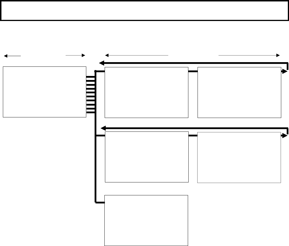
Function menu㻌
2. DETAIL menu structure which are displayed in the Pix monitor or are displayed in
the viewfinder with at control head mode.
MAIN MENU SUB-MENU
㻌
㻌㻌㻌㻌㻌㻌㻌㻌㻌㻌㻌㻌㻌㻌㻌㻌㻌㻌㻌㻌㻌㻌㻌㻌㻌㻌㻌㻌㻌㻌㻌㻌㻌㻌㻌㻌㻌㻌㻌㻌㻌㻌㻌㻌㻌㻌㻌㻌㻌㻌㻌㻌㻌㻌㻌㻌㻌㻌㻌㻌㻌㻌㻌㻌㻌
ڦ㹂㹃㹒㸿㹇㹊 㹋㹃㹌㹓 㹑㹁㹃㹌㹃 㸯
㹂㹃㹒㸿㹇㹊 㸸㸼㸼
㹑㹉㹇㹌 㹂㹒㹊 㸸㸼㸼
㹆㹇㹅㹆 㹁㹆㹐㹍㹋㸿㸸㸼
ڦ㹂㹃㹒㸿㹇㹊 㸯㸸㸼㹑㹁㹃㹌㹃㸯
㹊㹃㹔㹃㹊㸦㹑㹓㹀㸧 㸸 㸮
㹊㹃㹔㹃㹊㸸㸮
㹆 㹅㸿㹇㹌 㸸㸫㸯㸮㸮
㹔 㹅㸿㹇㹌 㸸㸫㸯㸮㸮
㹆 㹁㹐㹇㹑㹎 㸸 㸴㸮
㹔 㹁㹐㹇㹑㹎 㸸 㸴㸮
㹊㹃㹔㹃㹊 㹂㹃㹎 㸸 㸫㸲㸮
㹂㹒㹊 㹄㹐㹃㹏 㸸㸯㸵㹋㹆㹸
㹂㹃㹒㸿㹇㹊 㸸 㹍㹌
㹇㹌㹇㹒㹇㸿㹊㹇㹘㹃 㸸
ڦ㹑㹉㹇㹌 㹂㹒㹊 㸯㸸㸼 㹑㹁㹃㹌㹃 㸯
㹁㹆 㹑㹃㹊㹃㹁㹒 㸸㸯㹡㹦
㹁㹆㸯㸬㸿㸬㹎㹆㸿㹑㹃㸸㹎㹓㹑㹆 㸼 㸯㹑㹃㹁
㹑㸬㹂㹒㹊 㹊㹃㹔㹃㹊㸸㸫㸯㸰㸶
㹎㹆㸿㹑㹃㸸 㸷㸵 㹗㹣㸫㹐
㹕㹇㹂㹒㹆㸸㸮
㹁㹆㸰㸬㸿㸬㹎㹆㸿㹑㹃㸸㹎㹓㹑㹆 㸼 㸯㹑㹃㹁
㹑㸬㹂㹒㹊 㹊㹃㹔㹃㹊㸸㸮
㹎㹆㸿㹑㹃㸸㸮㹗㹣㸫㹐
㹕㹇㹂㹒㹆㸸㸮
㹇㹌㹇㹒㹇㸿㹊㹇㹘㹃 㸸
ڦ㹂㹃㹒㸿㹇㹊 㸰㸸㸺 㹑㹁㹃㹌㹃 㸯
㹂㸬㹉㹌㹃㹃 㹕㹆㹒 㸸 㸳㸮
㹂㸬㹉㹌㹃㹃 㹀㹊㹉 㸸 㸳㸮
㹎㸭㹌 㹀㸿㹊㸿㹌㹁㹃㸸 㸶㸭㸶
㹉㹌㹃㹃 㹂㹃㹒㸿㹇㹊㸸 㸫㸵㸮
㹂㹒㹊 㹑㹍㹓㹐㹁㹃 㸸㹐㸩㹅
㹂㹃㹒㸿㹇㹊 㸸㹍㹌
㹇㹌㹇㹒㹇㸿㹊㹇㹘㹃 㸸
ڦ㹆㹇㹅㹆 㹁㹆㹐㹍㹋㸿㸸㸺 㹑㹁㹃㹌㹃 㸯
㹐㸸㸮
㹅㸸㸮
㹀㸸㸮
㹆㹇㹅㹆 㹁㹆㹐㹍㹋㸿㸸 㹍㹄㹄
㹇㹌㹇㹒㹇㸿㹊㹇㹘㹃 㸸
ڦ㹑㹉㹇㹌 㹂㹒㹊 㸰㸸㸺 㹑㹁㹃㹌㹃 㸯
㹒㹆㹐㹃㹑㹆㹍㹊㹂 㸸㸫㸷㸴
㹑㹉㹇㹌 㹂㹃㹒㸿㹇㹊㸸㹍㹄㹄
㹑㹉㹇㹌 㹅㸿㹒㹃 㸸㹍㹄㹄
㹅㸿㹒㹃 㹇㹌㹂㸬 㸸㸯㹡㹦
㹇㹌㹇㹒㹇㸿㹊㹇㹘㹃 㸸
8
Function menu㻌
3. MAINTENANCE menu structure which are displayed in the Pix monitor or are
displayed in the viewfinder with at control head mode.
ڦ㹋㸿㹇㹌㹒㹃㹌㸿㹌㹁㹃 㹋㹃㹌㹓
㸿㹓㹒㹍 㹑㹃㹒㹓㹎 㸸㸼
㹕㹆㹒 㹑㹆㸿㹂㹇㹌㹅㸸㸼
㸿㹓㹒㹍 㹇㹐㹇㹑 㸸㸼
㹋㹇㹁 㹅㸿㹇㹌 㸸㸼
㹅㸿㹇㹌 㹑㹃㹒 㸸㸼
㹑㹆㹓㹒㹒㹃㹐 㸸㸼
㹑㹗㹑㹒㹃㹋 㸸㸼
㹒㹇㹋㹃㸭㹂㸿㹒㹃 㸸㸼
㹁㹆㹃㹁㹉 㸸㸼
ڦ㸿㹓㹒㹍 㹑㹃㹒㹓㹎㸺
㹁㹆㸯㸬㸿㸬㹎㹆㸿㹑㹃㸸㹎㹓㹑㹆 㸼㸯㹑㹃㹁
㹁㹆㸰㸬㸿㸬㹎㹆㸿㹑㹃㸸㹎㹓㹑㹆 㸼㸯㹑㹃㹁
㹅㹐㸿㹗 㹑㹁㸿㹊㹃 㸸㹎㹓㹑㹆 㸼㸯㹑㹃㹁
㹀㹊㸿㹁㹉 㹊㹃㹔 㸸 㸳㸬㸮㸮㸣
㹄㹊㸿㹐㹃 㹊㹃㹔 㸸 㸯㸰㸬㸮㸮㸣
㹅㸿㹋㹋㸿 㹊㹃㹔 㸸 㸳㸶ࠋ㸮㸮㸣
ڦ㹕㹆㹒 㹑㹆㸿㹂㹇㹌㹅㸺
㹃㹖㹒㹃㹌㹂㹃㹐㸸㹍㹄㹄㸦㹖㸯㸧
㹕㹆㹒 㹑㹆㸿㹂㹇㹌㹅㸸㹎㹓㹑㹆 㸼㸯㹑㹃㹁
㹐㹔㹑㸿㹕㸸㸮
㹅㹔㹑㸿㹕㸸㸮
㹀㹔㹑㸿㹕㸸㸮
㹇㹌㹇㹒㹇㸿㹊㹇㹘㹃 㸸
ڦ㸿㹓㹒㹍 㹇㹐㹇㹑 㸸㸺
㸿㹓㹒㹍 㹇㹐㹇㹑 㸸㹐㹃㹋㹍㹒㹃
㹇㹐㹇㹑 㹒㹐㹇㹋 㸸㸮
㹇㹐㹇㹑 㹑㹎㹃㹃㹂 㸸㸮
㹎㹃㸿㹉㸭㸿㹔㹃㸸㸮㸭㸯㸮
㹇㹐㹇㹑 㹅㸿㹒㹃 㸸㸯
㹍㹎㹃㹌 㹊㹇㹋㹇㹒㸸 㸯㸰㸵
㹁㹊㹍㹑㹃 㹊㹇㹋㹇㹒㸸 㸫㸶㸳
㹇㹌㹇㹒㹇㸿㹊㹇㹘㹃 㸸
ڦ㹋㹇㹁㹅㸿㹇㹌㸸㸺
㹋㹇㹁㸯 㸸㸫㸴㸮 㹢㹀
㹋㹇㹁㸰 㸸㸫㸴㸮 㹢㹀
㹄㹐㹍㹌㹒 㹋㹇㹁
㹎㹆㸿㹌㹒㹍㹋㸸㹍㹌
ڦ㹑㹗㹑㹒㹃㹋 㸸㸺
㹁㸿㹋㹃㹐㸿㹇㹂㸸㸯
㹄㸿㹌 㹋㹍㹂㹃 㸸㸿㹓㹒㹍
㹅㹊 㹆 㹎㹆㸿㹑㹃 㸸㸫㸳㸯㸰
㸿㹓㹂㹇㹍 㹒㹍㹌㹃 㸸 㹍㹄㹄
㹋㹍㹌㸭㹐㹃㹒 㹍㹓㹒㸸㹋㹍㹌㹇㹒㹍㹐
ڦ㹒㹇㹋㹃㸭㹂㸿㹒㹃 㸸㸺
㸦㸰㸱㸸㸳㸳㸸㸳㸳㸪㸰㸮㸮㸶㸫㸮㸲㸫㸰㸵㸧
㹗㹃㸿㹐 㸸㸰㸮㸮㸶
㹋㹍㹌㹒㹆㸸㸲
㹂㸿㹗㸸㸰㸵
㹆㹍㹓㹐㸸㸰㸱
㹋㹇㹌㹇㹒㹃㸸㸳㸳
㹑㹃㹒 㹂㸿㹒㸿 㸸㹎㹓㹑㹆 㸼
ڦ㹑㹆㹓㹒㹒㹃㹐 㸸㸺 㹑㹁㹃㹌㹃 㸯
㹑㹆㹓㹒㹒㹃㹐 㸸㹍㹄㹄
㹑㹆㹓㹒㹒㹃㹐 㹎㹐㹃㸸㸯㸭㸯㸮㸮
㹑㹆㹓㹒㹒㹃㹐 㹔㸿㹐㸸㸯㸭㸳㸷㸬㸷㸲
㹇㹌㹇㹒㹇㸿㹊㹇㹘㹃 㸸
ڦ㹁㹆㹃㹁㹉㸸㸺
㹒㹃㹑㹒㸸㹍㹄㹄
㹅㸿㹋㹋㸿㸸㹍㹌
㹂㹃㹒㸿㹇㹊㸸㹍㹌
㹋㸿㹑㹉㹇㹌㹅 㸸㹍㹄㹄
㹉㹌㹃㹃㸸㹍㹌
ڦ㹅㸿㹇㹌 㹑㹃㹒㸸㸺
㹋㸬㹅㸿㹇㹌 㹊㹍㹕 㸸 㸮 㹢㹀
㹋㸬㹅㸿㹇㹌 㹋㹇㹂 㸸 㸴 㹢㹀
㹋㸬㹅㸿㹇㹌 㹆㹇㹅㹆㹒㸸 㸯㸰 㹢㹀
SUB-MENU
MAIN MENU
9
Function menu㻌
4. FILE menu is displayed in the Pix monitor or are displayed in the viewfinder with at
control head mode.
5. SETUP CARD
ڦ㹄㹇㹊㹃 㹋㹃㹌㹓
㹄㹇㹊㹃 㹑㹃㹊㹃㹁㹒 㸸 㹑㹁㹃㹌㹃 㸮
㹑㹒㹍㹐㹃 㹄㹇㹊㹃 㸸 㹑㹁㹃㹌㹃 㸮
㹑㹒㹍㹐㹃
㸿㹊㹊 㹇㹌㹇㹒㹇㸿㹊㹇㹘㹃
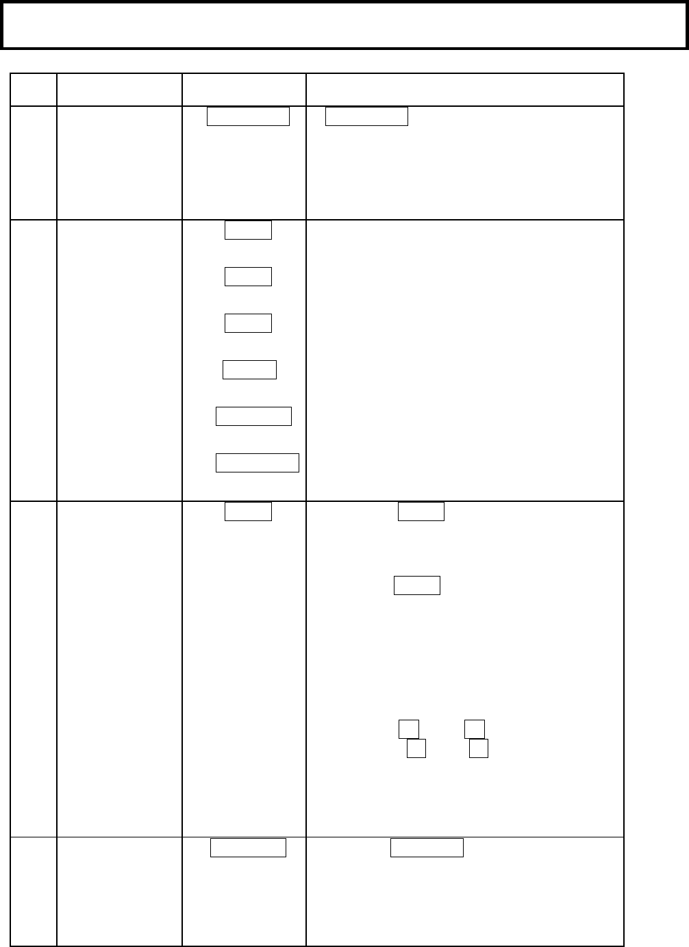
10
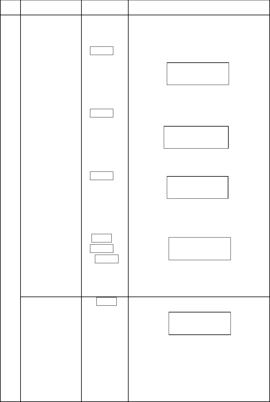
Operation procedure㻌
Item
no.Function SwitchOperating procedure
㸯Camera head&$032:(5 ࣭&$032:(5switch on
Power supply onThecamera head power on by this switch
pressing.
࣭The camera head power off by this switch
pressing more than 2 seconds continuously.
㸰On/off control%$56 ࣭Color bar on/off selection
7(67 ࣭Test signal on/off selection
0$6. ࣭HD masking on/off selection
%675࣭Black stretch on/off selection.
6.,1'7/࣭Skintone detail on/off selection.
$872.1(( ࣭Auto knee on/off selection.
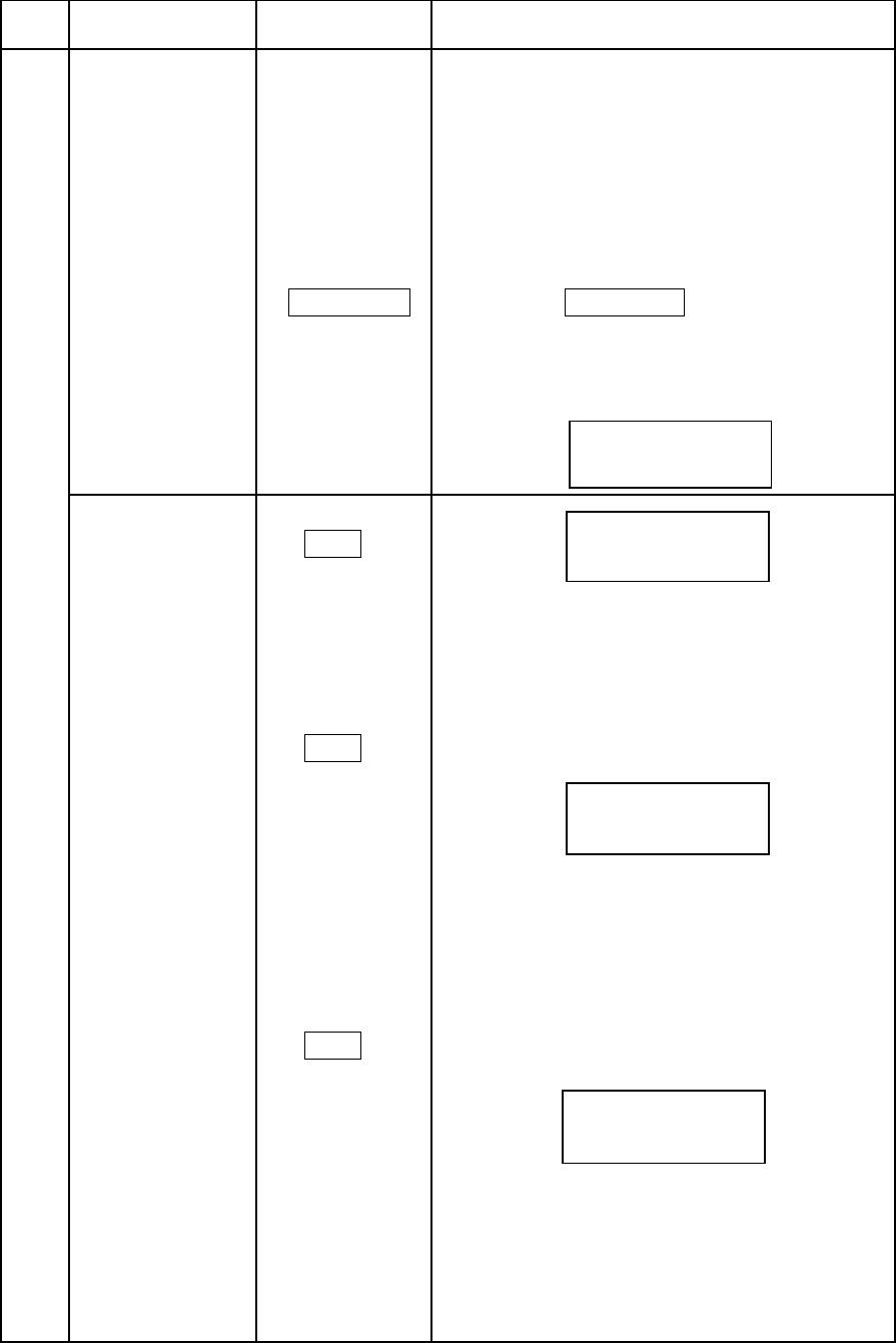
㸱Menu start 0(18 ࣭Press this 0(18button with Color bar on,
and display CCU menu screen on the pix
monitor.
࣭Press this 0(18 button with Color bar off,
and displays Camera Head menu screen on the
pix monitor.
(*)Please refer to the manual of CCU and
Camera Head for details.
Use the 㸺 ND 㸼(cursor up/down)
buttons and 㸺 CC 㸼(cursor left/right)
buttons to shift the cursor on the menu
screen
㸲Shift control
priority to the
camera head
&7/+($' 㺃Press the&7/+($'to shift control priority
(except the monitor select function) to the
camera head.
㺃Press the switch again and control priority
return to the RCU.
11
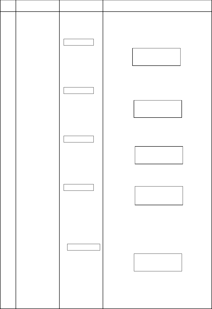
Item
no.FunctionSwitchOperating procedure
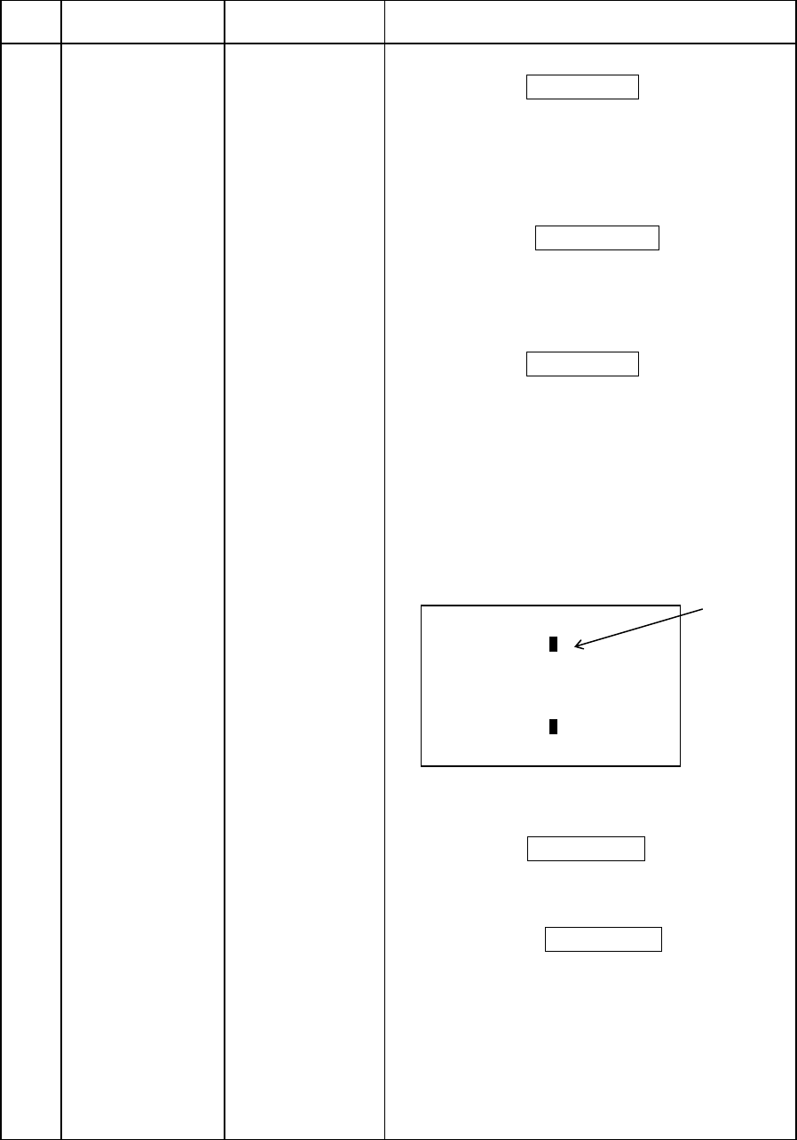
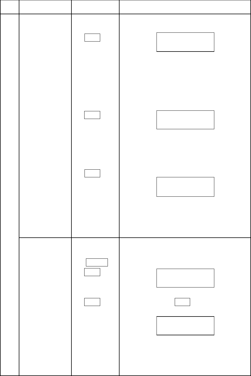
㸳AUTO SETUP$8726(783 ࣭Switch settings can be combined with the
following auto setup modes.
(;7&+$57 (1) Grayscale auto setup
(;7&+$57$8726(783
(2) Auto skin tone
(;7&+$572 times) $8726(783
(3) Auto Shading
(;7&+$573 times)$8726(783
1.Conduct grayscale auto setup by the
following procedure.
(1)Set the (;7&+$57switch to on to
show
the grayscale chart positioning markers
on the CCU pix monitor and viewfinder.
(2)Pickup the grayscale chart with the
markers positioned as shown in the
figure
(3)Press the $872 6(783 to start
grayscale auto setup.
(4) At error, the $8726(783LED flashes
for several seconds and the buzzer
sounds.
marker
12
Item
no.FunctionSwitchOperating procedure
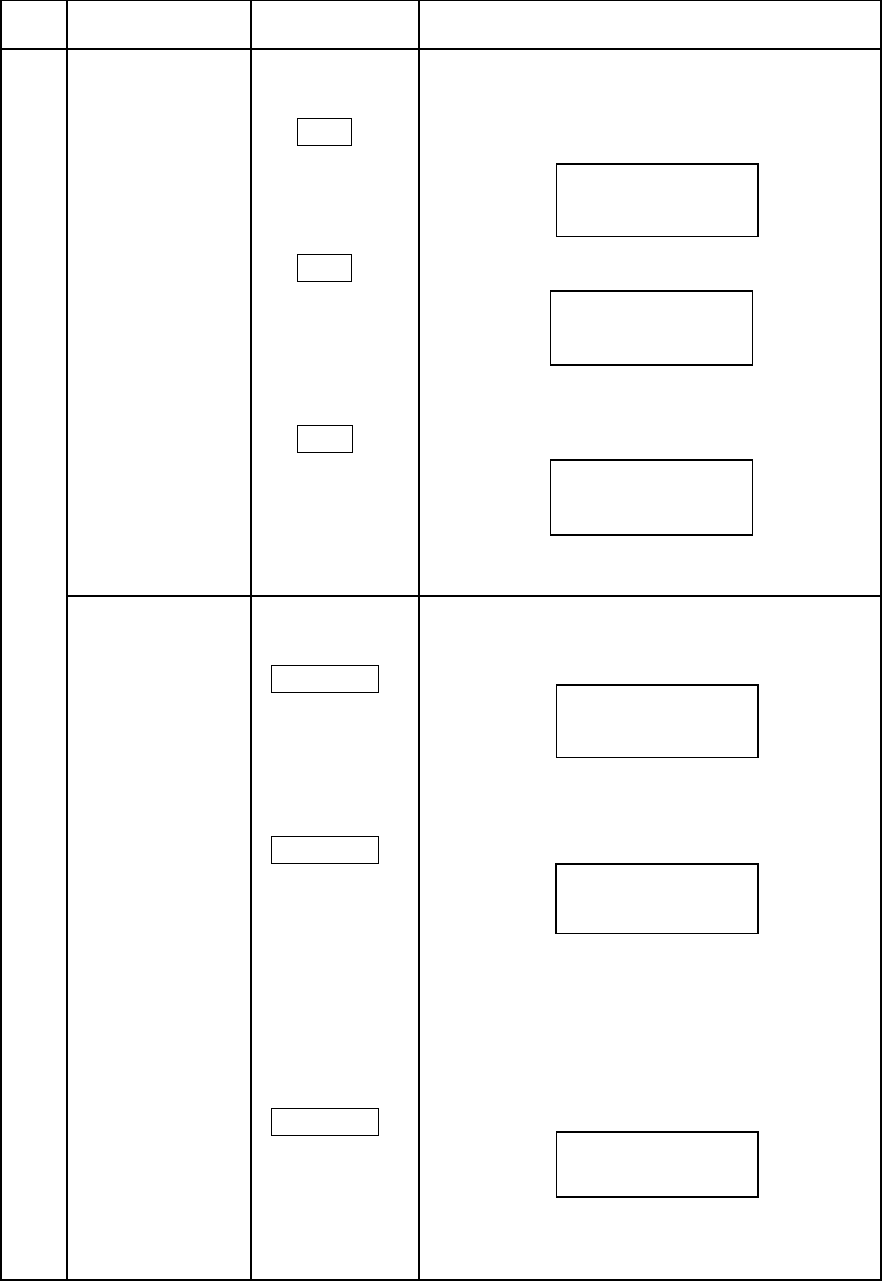
(㸳)AUTO SETUP2. Auto skin tone
(1) Press the (;7&+$57 times to show
the center marker on the viewfinder
and PIX monitor screen.
(2) Align the marker with the image for
color phase detection.
(3) Press the $8726(783 to detect the
color phase at the marker position and
revise the skin DTL phase data.
3.Auto shading
(1) Press the (;7&+$57 times to show
the marker for auto shading on the
viewfinder and PIX monitor screen.
(2)Pickup the white scene with the markers
positioned as shown in the figure
(3)Press the$8726(783for automatic
white shading (vs) adjustment.
(4) At error, the $8726(783LED fOashes
for several seconds and the buzzer
sounds.
marker
13
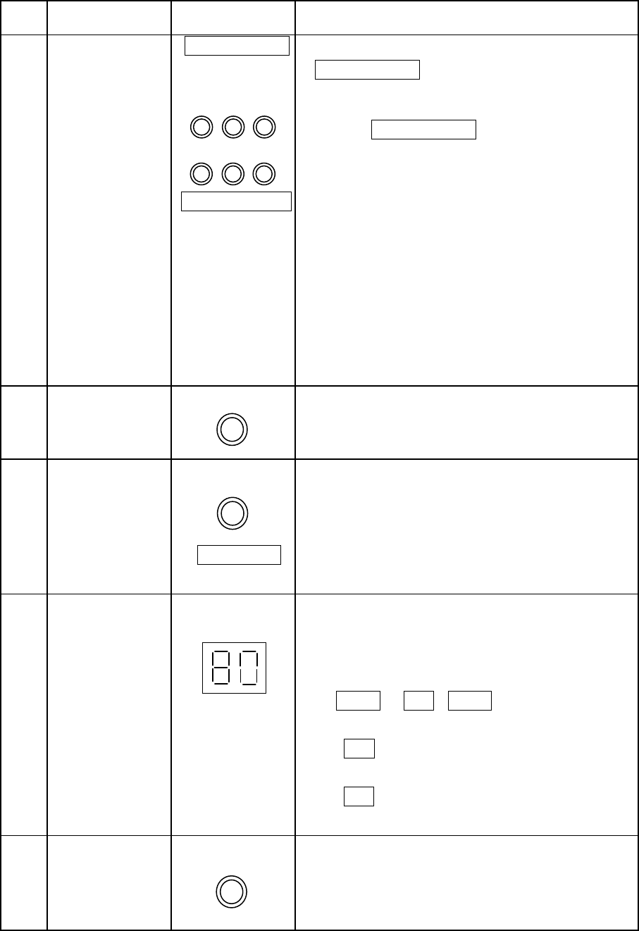
Item
no.FunctionSwitchOperating procedure
㸴AUTO WHITE$872:+,7( ࣭Pickup a white scene and press the
$872:+,7(for automatic white balance
adjustment.
࣭At error, the$872:+,7(LED flashes for
several seconds and the buzzer sounds.
㸵AUTO BLACK$872%/$&. ࣭Press the$872%/$&.to cut off the light
and automatically adjust the black balance.
࣭At error, the$872%/$&.LED flashes for
several seconds and the buzzer sounds.
㸶 Curtail auto setup %5($.2)) ࣭Press the%5($.2))during auto setup to
break off the auto setup process and the
buzzer sounds.
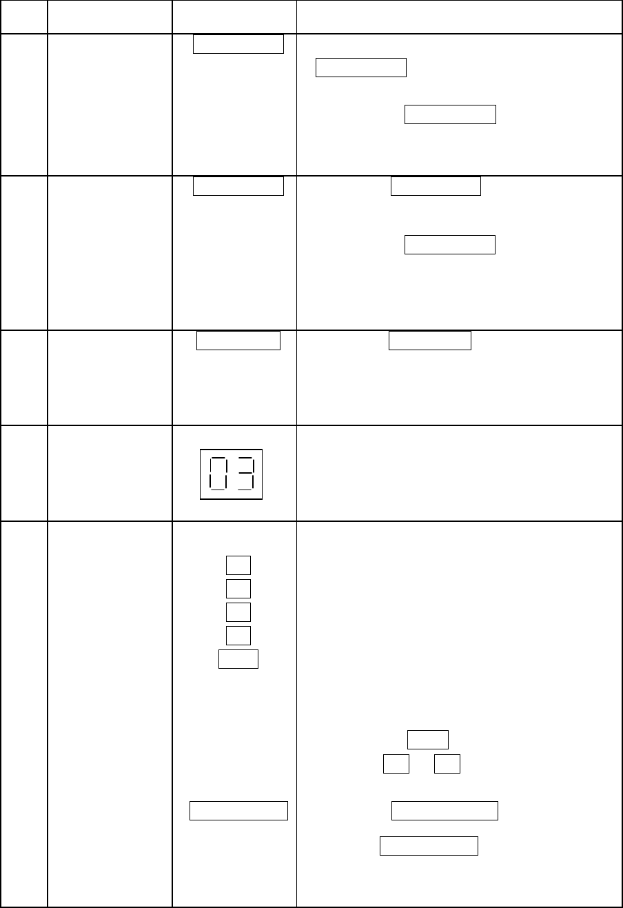
㸷CAM NO.&$012 ࣭Camera number is shown.
࣭Start the camera menu to set the camera
number.
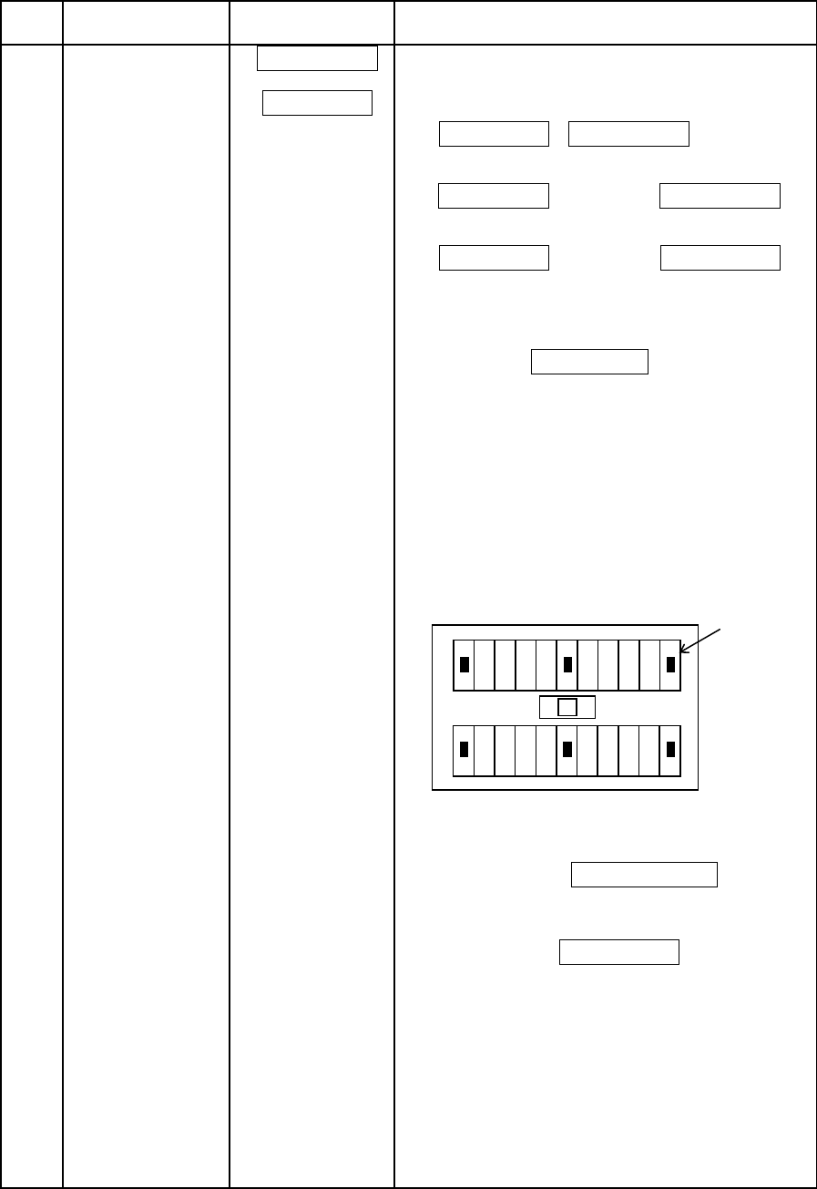
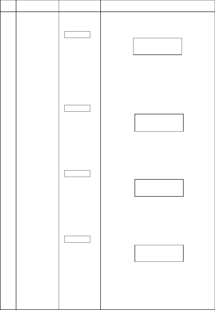
㸯㸮Scene file6&(1(),/( ࣭There are 9 scene files to 0-8 including 0
file.
selection ࣭Press scene file to access a scene file.
The LED lights.
࣭Press the switch while the LED is lit.
The LED extinguishes when the scene file
is deselected.
㺃When the all LED light turns off , scene file 0
is chosen.
㺃To select scene files 5 – 8 ,
set switches to on, then press
switches –
6&(1(35(6(7 ࣭Press the 6&(1( 35(6(7 until blink stops,
pre-set data is loaded.
Press the 6&(1(35(6(7 again until blink stop
the scene file data is loaded again.
14
Item
no.FunctionSwitchOperating procedure
㸯㸯Scene file 6&(1(),/( ࣭Scene file adjustment values can be stored
memory in memory by the following procedure.
(1) Press the 0(025<switch.
(2) The 0(025<LED begins blinking.
(3) Press the scene file ( – or
) for storing data in the memory.
0(025< (4) The selected scene file LED flashes and
the 0(025<LED lights for about 3
seconds. This completes storing memory.
The adjustment data of paint gain and
black can not be stored in memory,
To stop memory operation,
while the 0(025<LED is blinking,
press again the0(025<switch
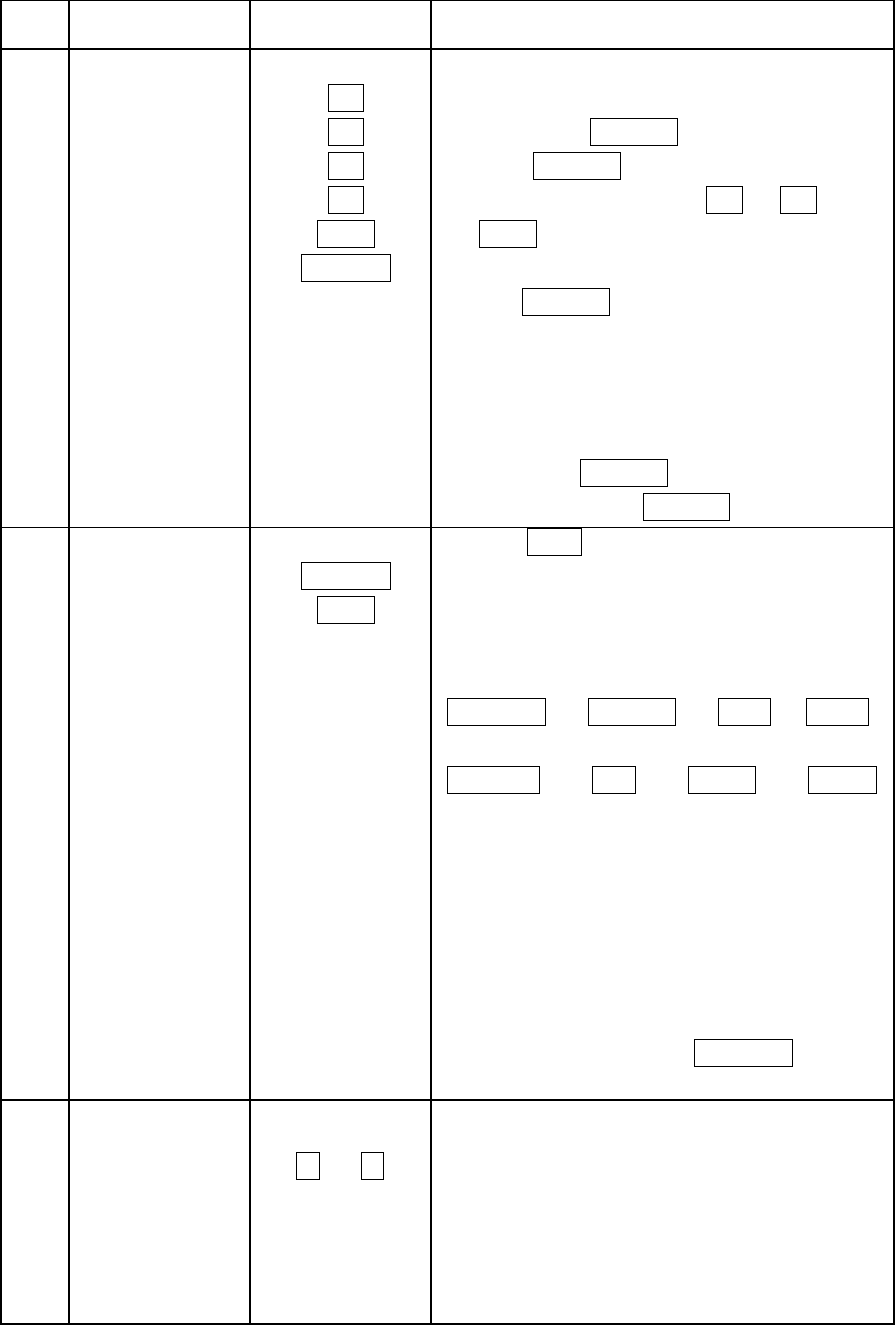
㸯㸰Shutter control6+877(5 ࣭Press6(/to toggle the shutter display
212)) on/off and select the shutter speed and
6(/ mode.
Insequence,1/100(*1),1/250,1/500,1/1000,
1/2000seconds, variable, AES,CCFR
&&)5(*2) Ѝ(*1) ЍЍ
ЌЎ
$(6(*3) ЋЋЋ
Variable mode
1/59 to 1/1983 (1080i/60)
1/50 to 1/2008 (1080i/50)
(*1) 1/60 ,when 1080i/50 CCD is used.
(*2) CCFR: cc frame mode
(*3) AES:auto electric shutter mode
࣭For variable mode, after selecting the
manual control section 6+877(5switch,
㸯㸱㻹㼍㼟㼠㼑㼞㻌㼓㼍㼕㼚㻌 0$67(5*$,1 ࣭Master gain can be selected in 3 dB
steps.
㼟㼑㼘㼑㼏㼠㼕㼛㼚㸺㸼(-3dB~24dB)
䞉Selected master gain position is indicated
by the LED on left of this switch.
15
Item
no.FunctionSwitchOperating procedure
㸯㸲㻺㻰㻛㻯㻯㻌㼒㼕㼘㼠㼑㼞㻌 㸺 1'㸼 ࣭ND/CC selects ND filters or CC(ECC)
㼟㼑㼘㼑㼏㼠㼕㼛㼚 filters. Each filters status are shown by
㸺 &&㸼 the upper sectionND/CC LEDs of these
switches.
LEDs and filters relationship are as
+($' shown below.
ND CC(ECC)
CAP:CAP A:3200K
1:CLEAR B:4300K
2:CROSS C:5600K
3:1/16ND D:6300K
4:1/64ND E:8000K
࣭When the+($'switch is set to on, the
ND/CC filter control from the camera head
and the RCU. Again press the+($'
switch to return control priority to the RCU.
࣭Press the for electrical 5600 K filter
status.
When the 0(18 switch is on (menu
mode), the ND/CC filter cannot be changed.
㸯㸳Monitor select5*% ࣭Selects analog pix monitor display signal.
(1&
683 ࣭Selects analog WFM monitor display signal.
6(4 683 / 6(4 : Display superimposes 3
RGB waveforms.
࣭SDI WFM monitor display signal
683 : superimposes mode.
6(4 : sequence mode.
When both the683and the 6(4 are
off, signal display is the same as pix monitor.
16
Item
no.FunctionSwitchOperating procedure
㸯㸴Manual adjustment࣭Select adjustment items with the manual
control section switches. The display
section shows the adjustment item and
value.
࣭Use the rotary encoder to adjust the items
for optimum values.
Adjustment &7/9$/8( ࣭When the&7/9$/8( switch is on, the
value displayadjustment value is displayed from -100 to
+100.
࠙Display exampleࠚ
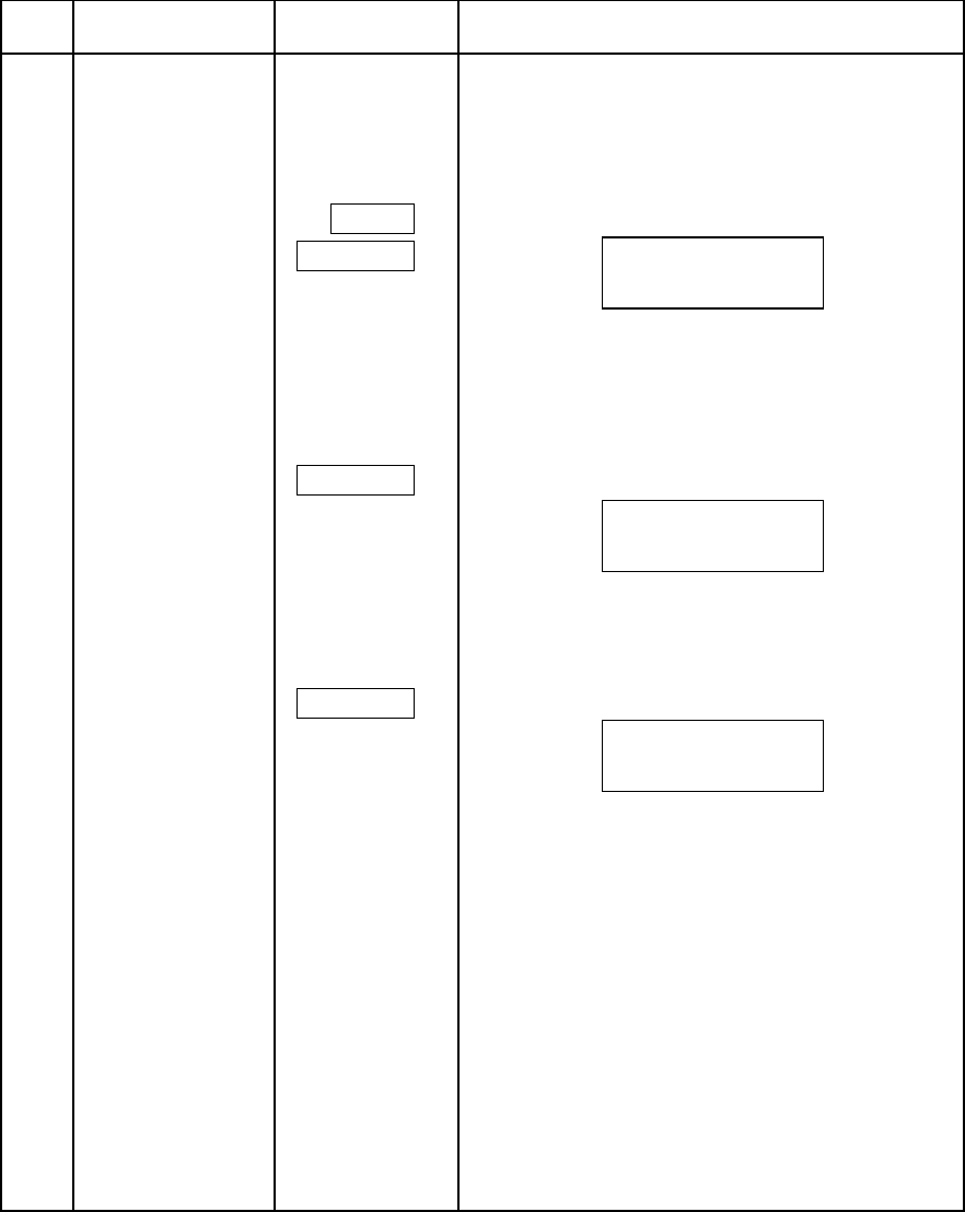
Detail Adjustment࠙Displayࠚ
(1)DTL LEVEL'7/
TOTL: Total detail level adjustment
H: H detail level adjustment
V: V detail level adjustment
(2)LEVEL DEP / '7/ ࣭Press again the switch for the following
BOOST FREQ display.
LDPP: Dark component noise due to detail
reduce.
FREQ: Adjusts detail boost frequency (13 M
to 19 M).
(3)CRISP / '7/ ࣭Press Again the switch for the following
DTL SOURCE display.
H-CR: Noise component reduction due to H.
detail.
V-CR: Noise component reduction due to V.
detail.
SRC: Detail signal source (R,RG,RGB)
selection.
/(9(/'(3)5(4
/'33)5(4
*$,1
'(7$,//(9(/
727/+9
&5,636285&(
+&59&565&
17
Item
no.FunctionSwitchOperating procedure
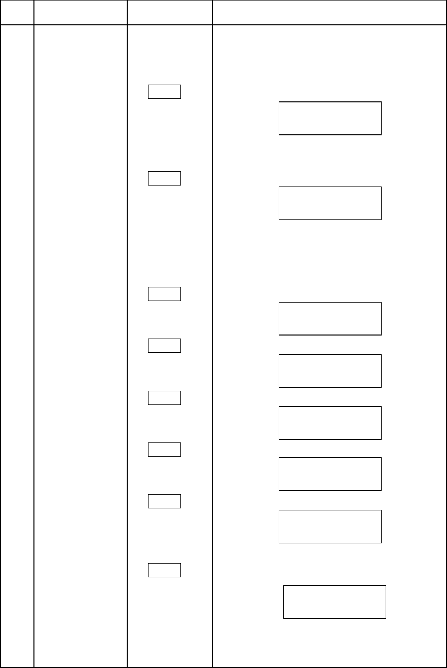
Manual adjustment
࣭ Press again the switch for the following display.
(4)DETAIL KNEE'7/
WHT: Additional white component glare
reduction.
BLK: Additional black component glare
reduction.
࣭Press the switch for the following display.
(5)BALANCE'7/
P/N: Detail positive (white) side adjustment
(4/8~8/4)
(6)WHITE DTL '7/ ࣭Pressagain the switch for the following display.
SLOP: White detail knee apeature
adjustment.
NTSC(PAL)
detail adjustment
(*)In the following figure ”NTSC” is displayed as
“PAL” in PAL mode.
(1)NTSC(PAL) 6+,)7 ࠙Displayࠚ
DTL LEVEL '7/
(2)NTSC(PAL) '7/࣭PressAgain the'7/switch for the
LEVEL DEP / following display.
BOOST FREQ
FREQ: Boost frequency (4 M to 8 M)
'(7$,/.1((
:+7%/.
%$/$1&(
31
.1(('7/
6/23
176&'7//(9(/
727/+9
176&/'3)5(4
/'33/'36)5(4
18
Item
no. Function SwitchOperating procedure
Manual adjustment
(3)NTSC(PAL) '7/࣭Press again the switch for the following display.
CRISP
(4)NTSC(PAL) '7/࣭Press again the switch for the following display.
DTL KNEE
(5)NTSC(PAL) '7/࣭Press again the switch for the following display.
BALANCE
Skin detail
adjustment
(1)SKIN DTL 6.,1'7/ ࠙Displayࠚ
LEVEL
(Ch1)
LEVL: Skin color detail level adjustment
(2)PHASE/WIDTH6.,1'7/ ࣭Press again the switch for the following display.
(Ch1)
PH-C: Skin color phase select (coarse adjustment)
(R-MG,MG-B,B-CY,CY-G,G-YE,YE-R)
PHAS: Skin color phase select (fine adjustment)
WIDH: Skin color phase range select
(3)SKIN DTL 6.,1'7/
LEVEL
(Ch2)
LEVL: Skin color detail level adjustment
176&&5,63
+&59&5
176&'7/.1((
:+7%/.
176&%$/$1&(
3/
6.,1'(7$,/
/(9/
6.,1'(7$,/
3+&3+$6:,'+
6.,1'(7$,/
/(9/
19
Item
no.Function Switch Operating procedure
Manual
adjustment
(4)PHASE/WIDTH6.,1'7/ ࣭Press again the switch for the following display.
(Ch2)
PH-C: Skin color phase select (coarse adjustment)
(R-MG,MG-B,B-CY,CY-G,G-YE,YE-R)
PHAS: Skin color phase select (fine adjustment)
WIDH: Skin color phase range select
(5)CHROMA6.,1'7/ ࣭Press again the switch for the following display.
LEVEL-DEP
THRH: Skin detail reduction by color phase
adjustment
(6)CHROMA6.,1'7/ ࣭Press again the switch for the following display.
LEVEL-DEP
THRH: Skin detail reduction by color phase
adjustment
(7)HIGH6.,1'7/ ࣭Press again the switch for the following display.
CHROMA
High chroma detail adjustment (R,G,B)
6.,1'(7$,/
3+&3+$6:,'+
&+520$/(9(/'(3
7+5+
&+520$/(9(/'(3
7+5+
+,*+&+520$
5*%
20
Item
no. Function SwitchOperating procedure
Manual Adjustment
㻱㻺㻯㻌㼠㼕㼙㼕㼚㼓㻌
㼍㼐㼖㼡㼟㼠
(1)ENC TIMING6+,)7 ࠙Displayࠚ
6.,1'7/
SC-C: Subcarrier phase adjustment (coarse)
SC-P: Subcarrier phase adjustment (fine)
H-P: H phase adjustment
(2)Y/C LEVEL6.,1'7/ ࣭Again press the switch for the following display.
Y: Encoder Y level adjust
C: Encoder C level adjust
(3)ENC TIMING 26.,1'7/ ࣭Again press the switch for the following display.
H-C: H phase adjust (coarse)
(1&7,0,1*
6&&6&3+3
<&/(9(/
<&
(1&7,0,1*
+&
21
Item
no. Function SwitchOperating procedure
Manual adjustment
Masking adjustment
(1)Skintone 0$6. ࠙Displayࠚ
SAT: Skintone saturation adjustment
HUE: Skintone hue adjustment
(2) R (Red)0$6. ࣭Again press the switch for the following display.
SAT: R (red) saturation adjustment (following
the same for each color).
HUE: R (red) hue adjustment (following the
same for each color).
(3) Y-R0$6. ࣭Again press the switch for the following display.
(Yellow-Red)
(4) Y (Yellow) 0$6. ࣭Again press the switch for the following display.
(5) G-Y0$6. ࣭Again press the switch for the following display.
(Green-Yellow)
(6) G (Green)0$6. ࣭Again press the switch for the following display.
(7) C-G0$6. ࣭Again press the switch for the following display.
(Cyan-Green)
(8) C (Cyan)0$6. ࣭Again press the switch for the following display.
6.,1721(0$6.
6$7+8(
0$6.5
6$7+8(
0$6.<5
6$7+8(
0$6.<
6$7+8(
0$6.*<
6$7+8(
0$6.*
6$7+8(
0$6.&*
6$7+8(
0$6.&
6$7+8(
22
Function Switch Operating procedure
Manual adjustment
(9) B-C 0$6. ࣭Again press the switch for the following display.
(Blue-Cyan)
(10) B (Blue) 0$6. ࣭Again press the switch for the following display.
(11) M-B 0$6. ࣭Again press the switch for the following display.
(Magenta-Blue)
(12) M (Magenta)0$6. ࣭Again press the switch for the following display.
(13) R-M 0$6. ࣭Again press the switch for the following display.
(Red-Magenta)
(14)CHROMA SAT0$6. ࣭Again press the switch for the following display.
LEVL: Master Chroma saturation adjustment
(15) Linear matrix 10$6. ࣭Again press the switch for the following display.
Linear matrix R-G, R-B and G-R adjustment
(16) Linear matrix 20$6. ࣭Again press the switch for the following display.
Linear matrix G-B, B-R and B-G adjustment
0$6.%&
6$7+8(
0$6.%
6$7+8(
0$6.0%
6$7+8(
0$6.0
6$7 +8(
0$6.50
6$7+8(
&+520$6$7
/(9/
0$6./,1
5*5%*5
0$6./,1
*%%5%*
23
Item
no.FunctionSwitch Operating procedure
Manual adjustment
Shutter adjustment6+877(5 ࠙Displayࠚ
VAR: Variable adjust
1/59~1/1983 (1080i/60)
1/50~1/2008 (1080i/50)
Set the upper shutter SEL switches
to variable mode when Variable adjustment.
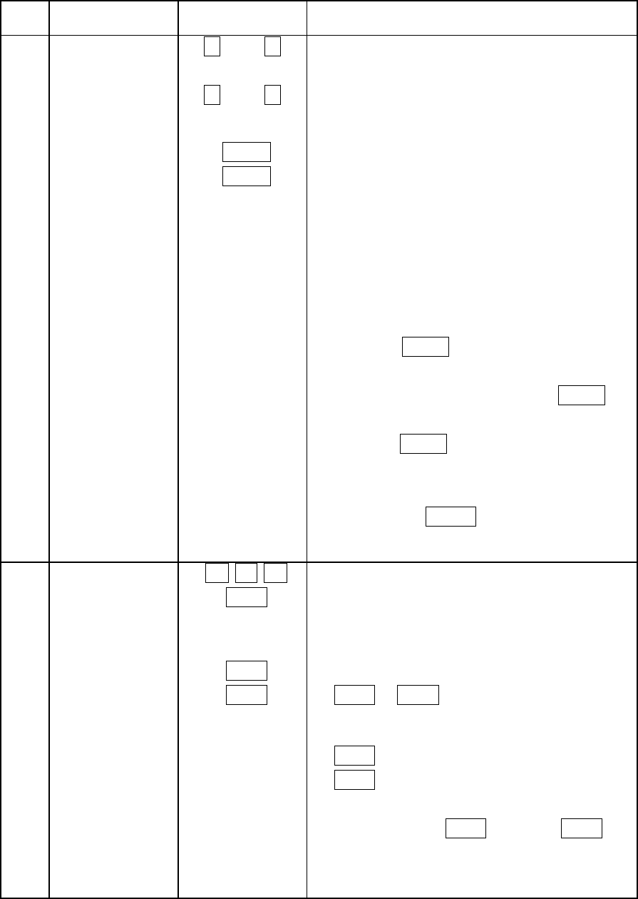
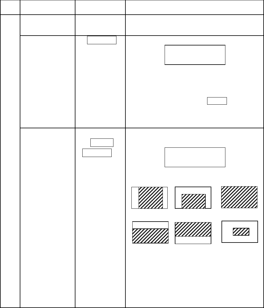
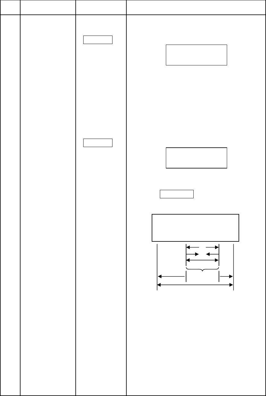
Auto iris adjust
(1)IRIS GATE6+,)7 ࠙Displayࠚ
6+877(5
Gate: Auto iris gate selection (1 – 6, see figure)
The above gate signal is displayed also on
CCU pix monitor.
$872,5,6
*$7(
6+877(5
9$5
24
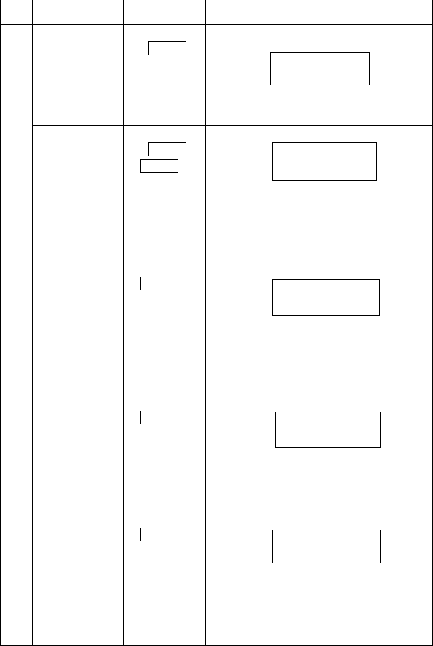
Item
no.FunctionSwitchOperating procedure
Manual adjustment
(2)IRIS TRIM 6+877(5 ࣭Press again the switch for the following display.
SPED: Adjusts the auto iris response speed.
If response speed becomes fast then adjustment
value will be big and adjustment value become
small then response speed will be slow.
P/AV: Adjusts the ratio between peak and
average.(0/10㹼5/5)
(3)IRIS RANGE 6+877(5 ࣭Press again the switch for the following display.
Adjust the range and sense for manual iris
control.
Press the &7/9$/8( for the following display.
$872,5,6
63(' 3$9
,5,65$1*(
5$1* 6(16
IRIS SENSE
ڧڧڧڧڧڧڦڦڦڦڦڦڦڧڧڧ
㸩㸰㸮㸫㸰㸮
IRIS RANGE
CLOSE
POSITION OPEN
POSITION
㸩㸫
㸩
㸫
25
Item
no.FunctionSwitchOperating procedure
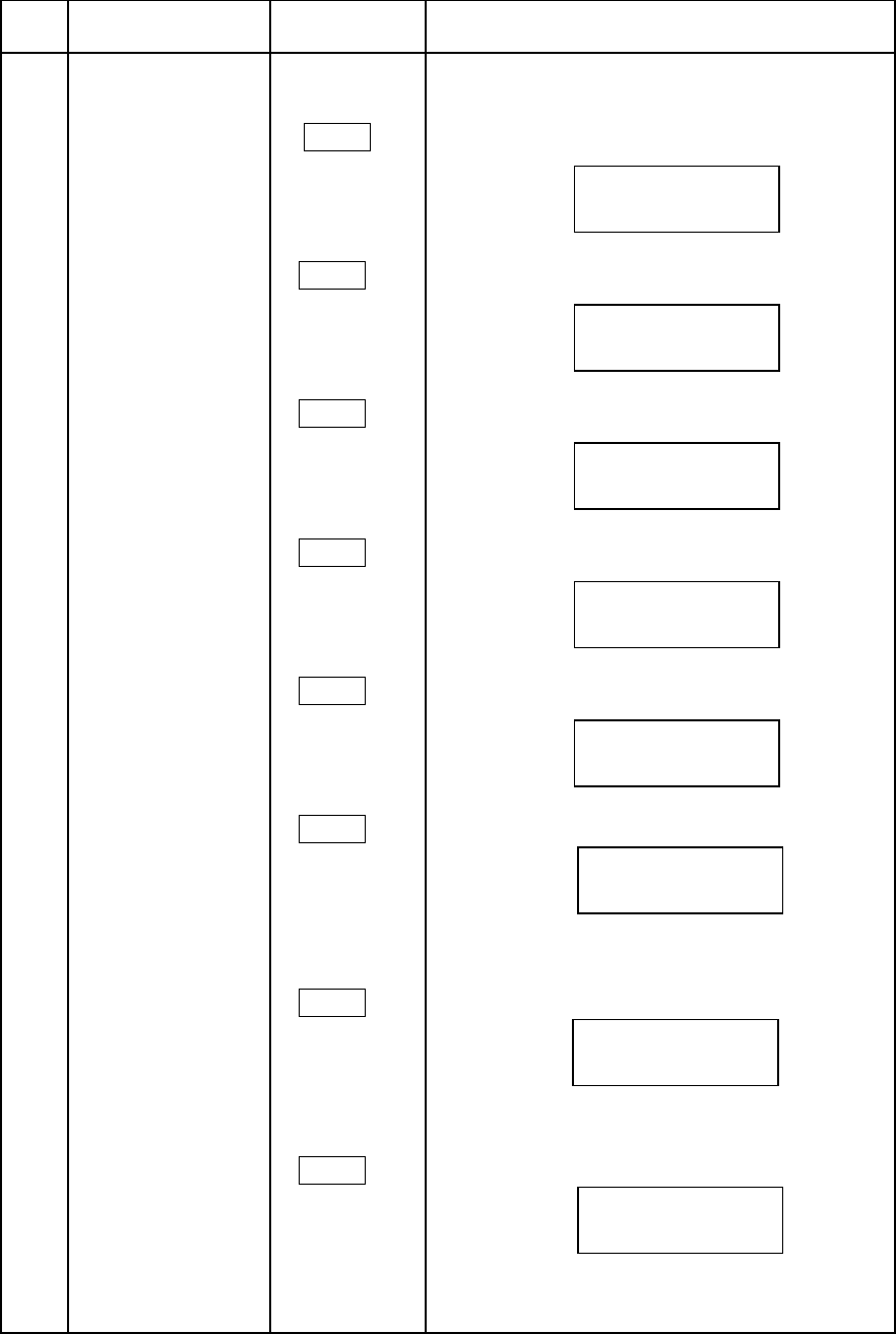
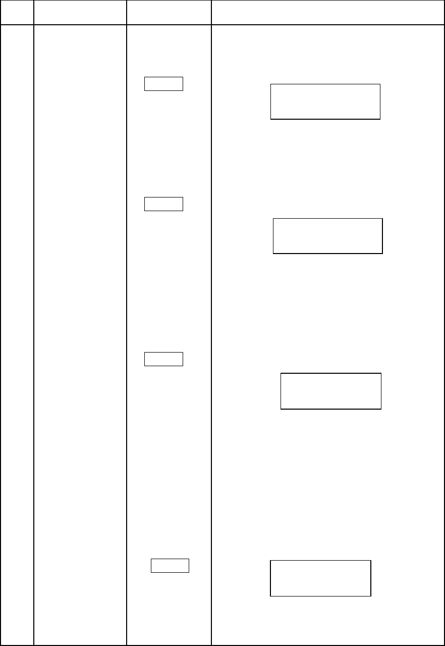
Manual adjustment
Black stretch%675 ࠙Displayࠚ
adjustment
LEVL: Black stretch level adjustment
On/off control
(1) DTL6+,)7 ࠙Displayࠚ
DTL KNEE%675
SKIN GATE
DTL: Detail on/off
DTLKNE: Detail knee on/off
GATE: Skintone gate on/off
࣭ Press again the switch for the following display.
(2) KNEE%675
W.CLIP
GAMMA
KNEE: Knee on/off
WCLIP: White clip on/off
GAMMA: Gamma on/off
࣭ Press again the switch for the following display.
(3)PAINT GAMMA%675
SKINTONE-
MASKING
P-GAMMA: Paint gamma on/off
S-MASK: Skintone masking on/off
࣭ Press again the switch for the following display.
(4)KNEE SAT%675
CHROMA SAT
HIGH CHROMA
KNSAT: Knee saturation on/off
CSAT: Chroma saturation on/off
HICRM: High chroma detail on/off
%/$&.675(7&+
/(9/
'7/'7/.1(*$7(
21212))
.1((:&/,3*$00$
212121
3*$00$ 60$6.
2121
.16$7&6$7+,&50
212121
26
Item
no. Function SwitchOperating procedure
Manual adjustment
࣭Press again the switch for the following display.
(5)SKINDTL-%675
CH,IND
CH:Select skintone detail channel (1,2,1+2)
IND:Select skintone gate channel l (1,2)
(6) ASPECT%675 ࣭Press again the switch for the following display.
COMB FILTER
MONO
ASPCT: Selects aspect ratio (16:9 or 4:3)
COMB: NTSC(PAL) output comb filter on/off
MONO: Mono color on/off
(7) N-DTL(P-DTL) %675 ࣭Press again the switch for the following display.
W/N
N-DTL: NTSC(PAL) detail on/off
W/N: Aspect change control
( REM:System side, LOCL:SCU/RCU side)
(*) In PAL mode, “N-DTL” is displayed as
“P-DTL”.
(8) RATE CONV %675
ON/OFF
HD-MODE: Rate change control (1080I/720P)
&+̽ 6.,1'7/̽ ,1'
$63&7&20%0212
212))
1'7/:1
21/2&/
+'02'(
3
27
Item
no.Function Switch Operating procedure
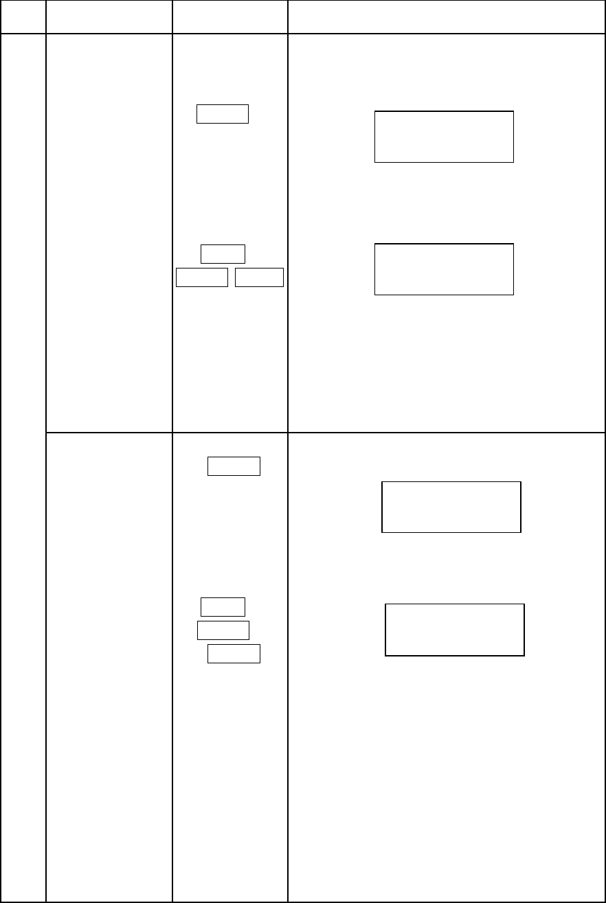
Manual adjustment
BLACK adjustment
(1) BLACK%/$&. ࠙Displayࠚ
Pedestal (RGB) adjustment
(2) BLACK 0(18
SETUP LEVEL 6+,)7%/$&.
Black setup level adjustment
(0~12.3%)
Flare adjustment
(1)FLARE )/$5( ࠙Displayࠚ
Flare (RGB) adjustment
(2) FLARE 0(18
SETUP LEVEL 6+,)7
)/$5(
Flare setup level adjustment
(0~24.7%)
%/$&.
5*%
6(783/(9(/
)/$5(
5*%
6(783/(9(/
28
Item
no.Function Switch Operating procedure
Manual adjustment
Gamma adjustment
(1) GAMMA*$00$ ࠙Displayࠚ
Gamma (R, G, B) adjustment
(2) PAINT*$00$ ࣭ Press again the switch for the following display.
- GAMMA
Paint gamma (R,TOTL, B) adjustment
(3) GAMMA*$00$
TABLE
Special gamma (rising component) adjustment
(3.0~8.0(0.5step))
(4) GAMMA 0(18
SETUP LEVEL 6+,)7
*$00$
Gamma setup level adjustment
(42.2~67.7%)
Gain adjustment*$,1 ࠙Displayࠚ
Gain (RGB) adjustment
3$,17*$00$
5727/%
*$00$
5*%
*$00$7$%/(
727/
6(783/(9(/
*$,1
5*%
29
Item
no. Function Switch Operating procedure
Manual adjustment
Knee/slope
adjustment
(1) KNEE.1((6/23( ࠙Displayࠚ
Knee point (R, total. B) adjustment
(2) SLOPE.1((6/23( ࣭Press again the switch for the following display.
Slope (R, total, B) adjustment
(3)WHITE CLIP.1((6/23( ࣭Press again the switch for the following display.
White clip (total) adjustment
(4)KNEE SAT.1((6/23(
Knee saturation level adjustment
White shading
adjustment
:+,7(6+$' ࣭Press again the switch for the following display.
:hite shading v saw (R,G,B) adjustment
.1((
5727/%
6/23(
5727/%
:+,7(&/,3
727/
.1((6$7
/(9/
:+,7(6+$'96
5*%
30
Item
no.Function Switch Operating procedure
㸯㸵Gain and black 3$,17(1$%/( ࣭Gain and black adjustment with
adjust 3$,17(1$%/(switch on
Adjustable by control
*$,1
࣭Setting3$,17(1$%/(to off returns
%/$&. black control to center detent position.
G.gain/C.temp
adjust **$,1&7(03 Set to C.Temp to operate the G.Gain control as
follows.
Turn clockwise to raise blue and lower red gain.
Turn counter-clockwise raise red and lower blue gain.
When switch is set to G.Gain:
Turn clockwise to simultaneously lower red and blue
gain.
Turn counter-clockwise to simultaneously raise red
and blue gain.
㸯㸶Detail adjustment'7/ ࣭Detail level can be adjusted by turning the
control.
㸯㸷Iris adjustment,5,6 ࣭Iris adjustment. When using joystick ,operate
by up and down movement.
࣭During auto iris, joystick up&down or manual
iris trimmer control can be used for fine
adjustment.
Auto iris on/off$872,5,6࣭Auto iris on/off is selected.
㸰㸮Iris F value Set as below according to camera usage
indication,5,6mode.
(1) Normal use
Lens F value is indicated.
– &/
(2) Camera power supply off
(3) The lens cable is open
RR
㸰㸯Master black 0$67(5%/$&. ࣭Master black can be adjusted by the mounted
master control knob for JY type.
adjust ࣭Master black can be adjusted by variable
Register for VR type.
䡡

31
Item
no.FunctionSwitchOperating procedure
㸰㸰Lens extender; ࣭Lights when lens extender X2 is on.
Indication
; ࣭Lights when lens extender X0.8 is on.
㸰㸱TALLY CALL&$// ࣭R tally LED lights when&$//switch is
pressed.
࣭Tally call from camera head and CCU:
The R tally LED lights and the buzzer
sounds.
㸰㸲Preview switch
(JY type only)
㺃Press the joystick inward to short the Preview
connector pins #2 and #3 in the rear panel.
Connect the Preview connector to a video
switcher via the accessory RM12BPE-3S plug
and use to view the camera video signal on the
master monitor.
㸰㸳Message࣭"CAM POWER OFF"
displayCamera head power supply is off.
࣭"SK-HD1000"
Camera head type is indicated when
camera head power is on.
࣭"AUTO SETUP"
Auto setup in progress.
࣭"CONTROL HEAD"
Control priority is camera head.
㸰㸴TALLY LED ࣭Red or Green tally can be lighted.
(Red/Green)
㸰㸵EXTENDER LED ࣭Extender LED lights when Lens extender
is selected.
32
Service information
33
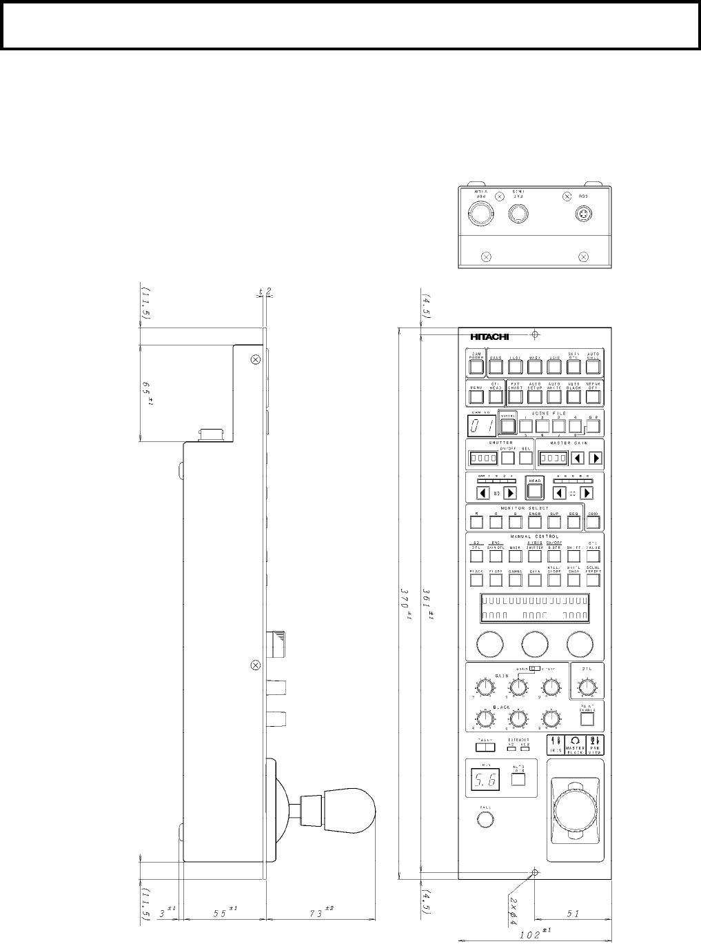
Specifications
Rating
(1) Dimensions: 102 (W) x 370 (D) x 55 (H) mm
(2) MASS: 1.5 kg
(3) Power input: DC+12V
(4) Ambient temperature: 0 to +40 qC
Dimensions
RU-1200JY
34
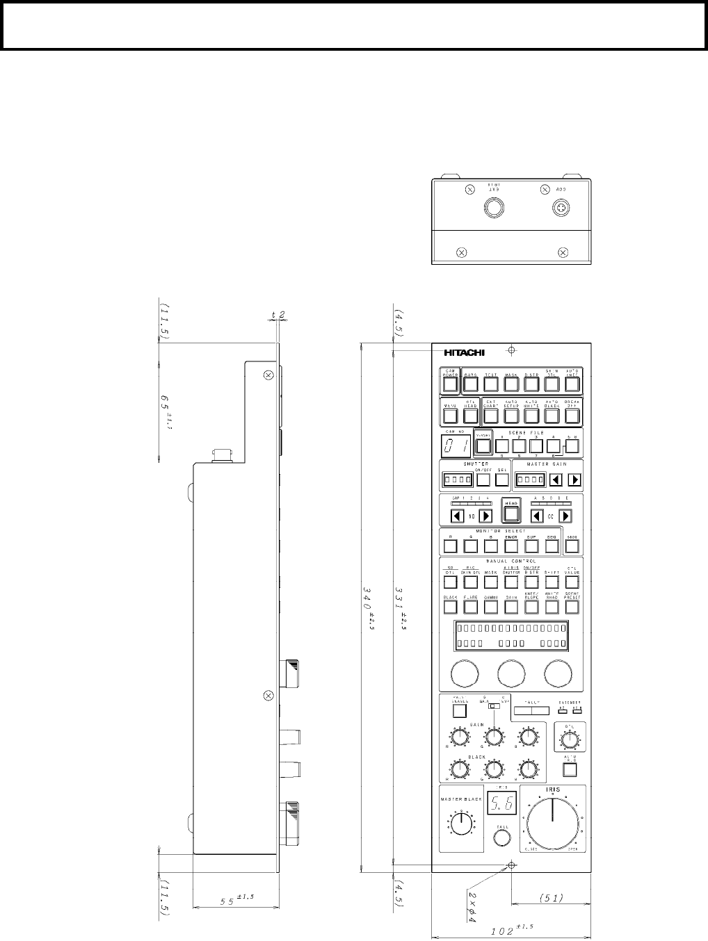
Specifications
Rating
(1) Dimensions: 102 (W) x 340 (D) x 55 (H) mm
(2) MASS: 1.5 kg
(3) Power input: DC+12V
(4) Ambient temperature: 0 to +40 qC
Dimensions
RU-1200VR
㻌
㻌
