Hitec RCD HPF-M72 R/C of Model Aircraft User Manual User Instructions
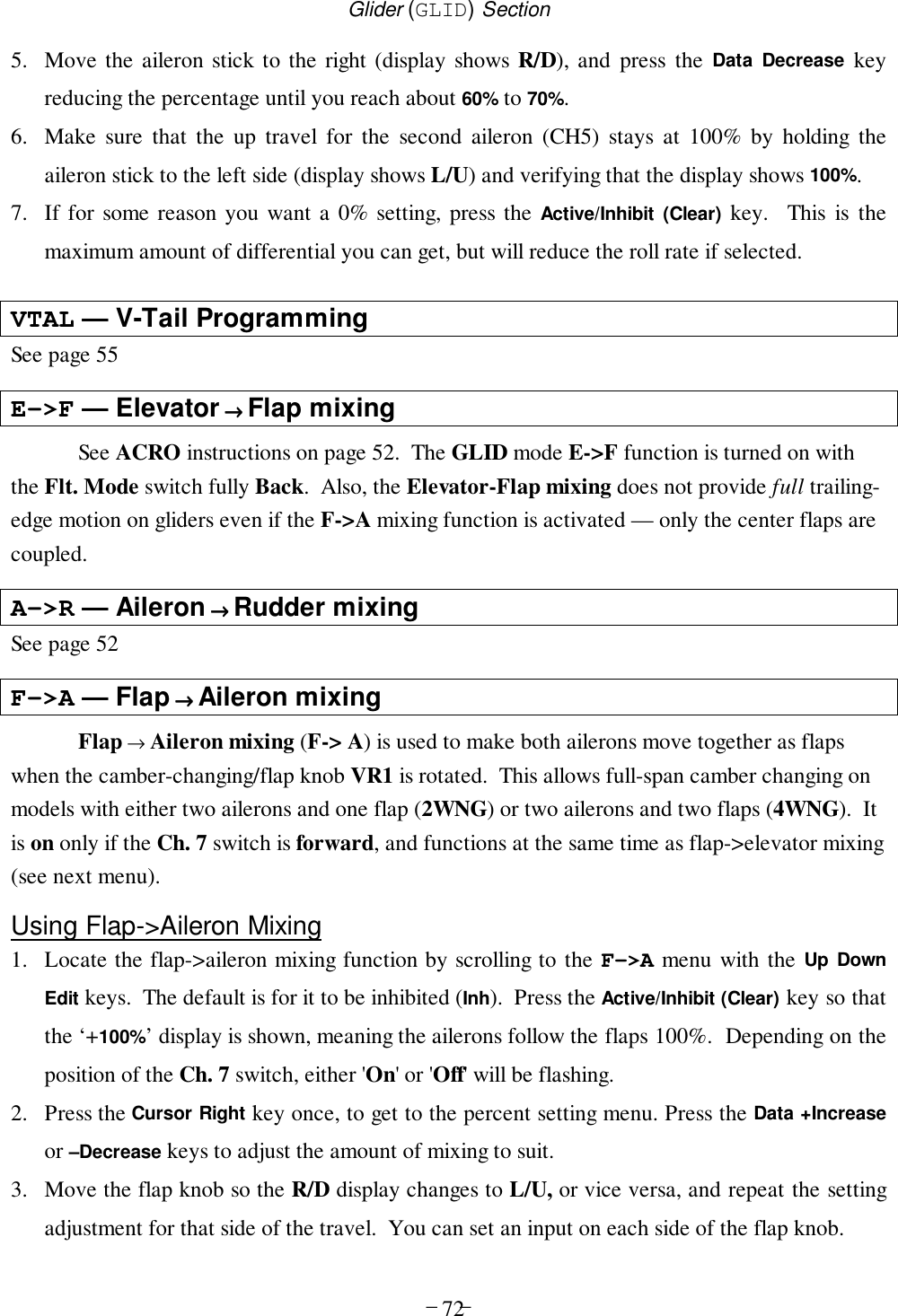
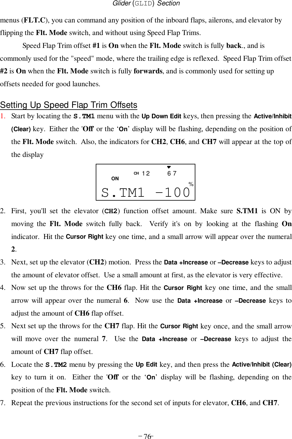
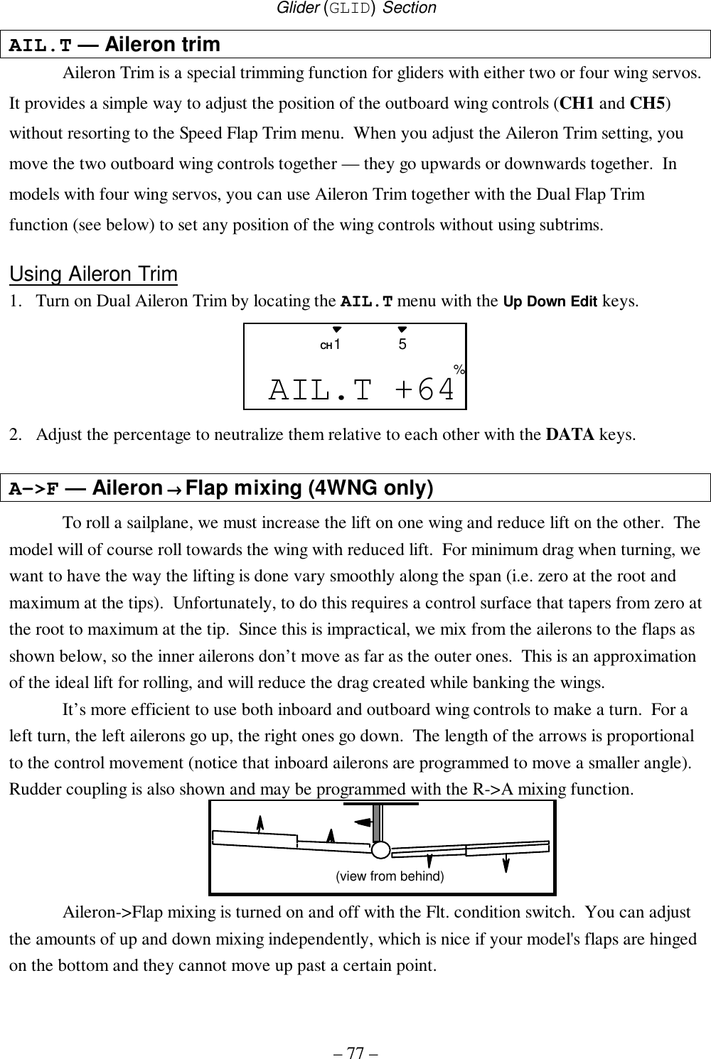
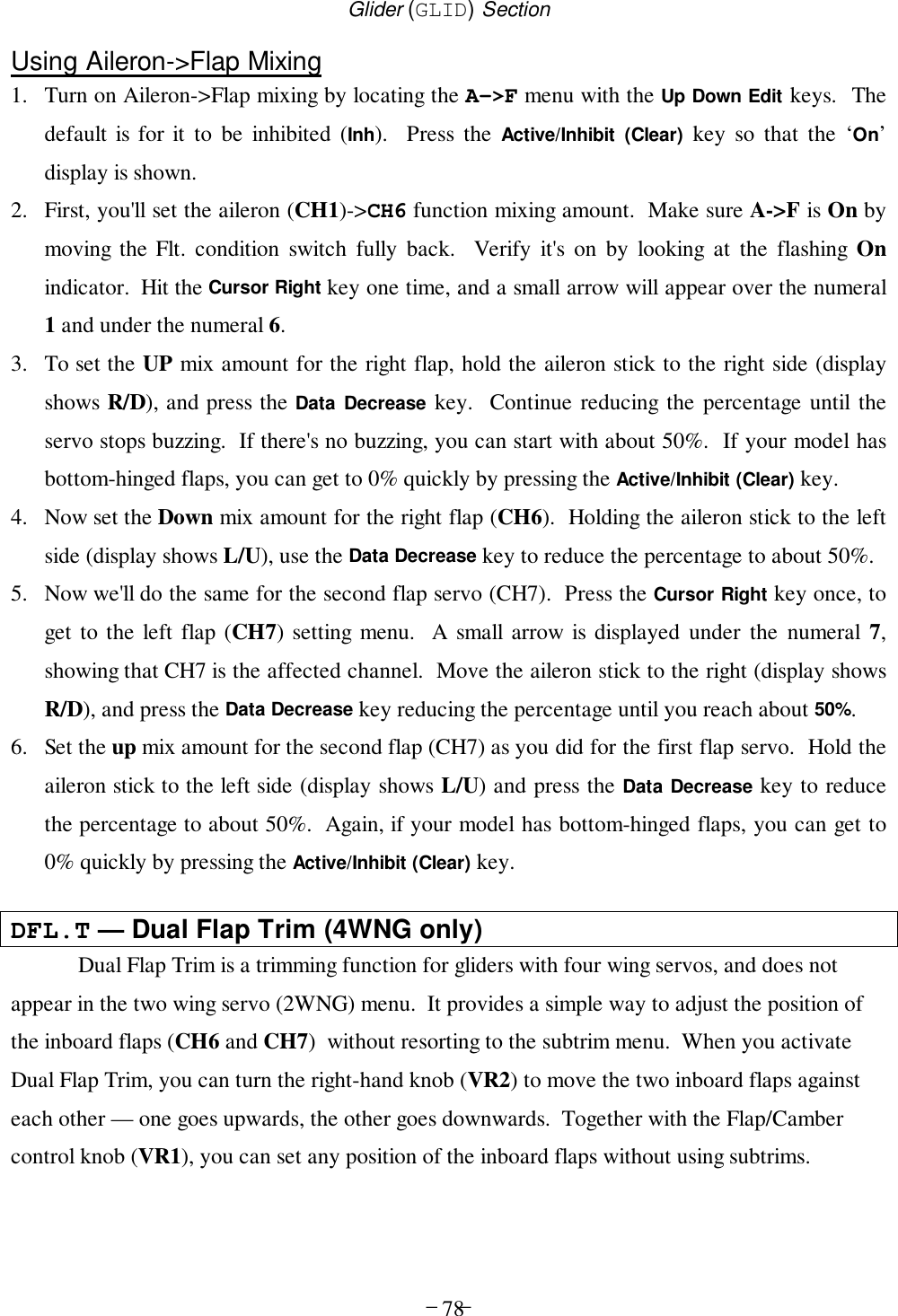
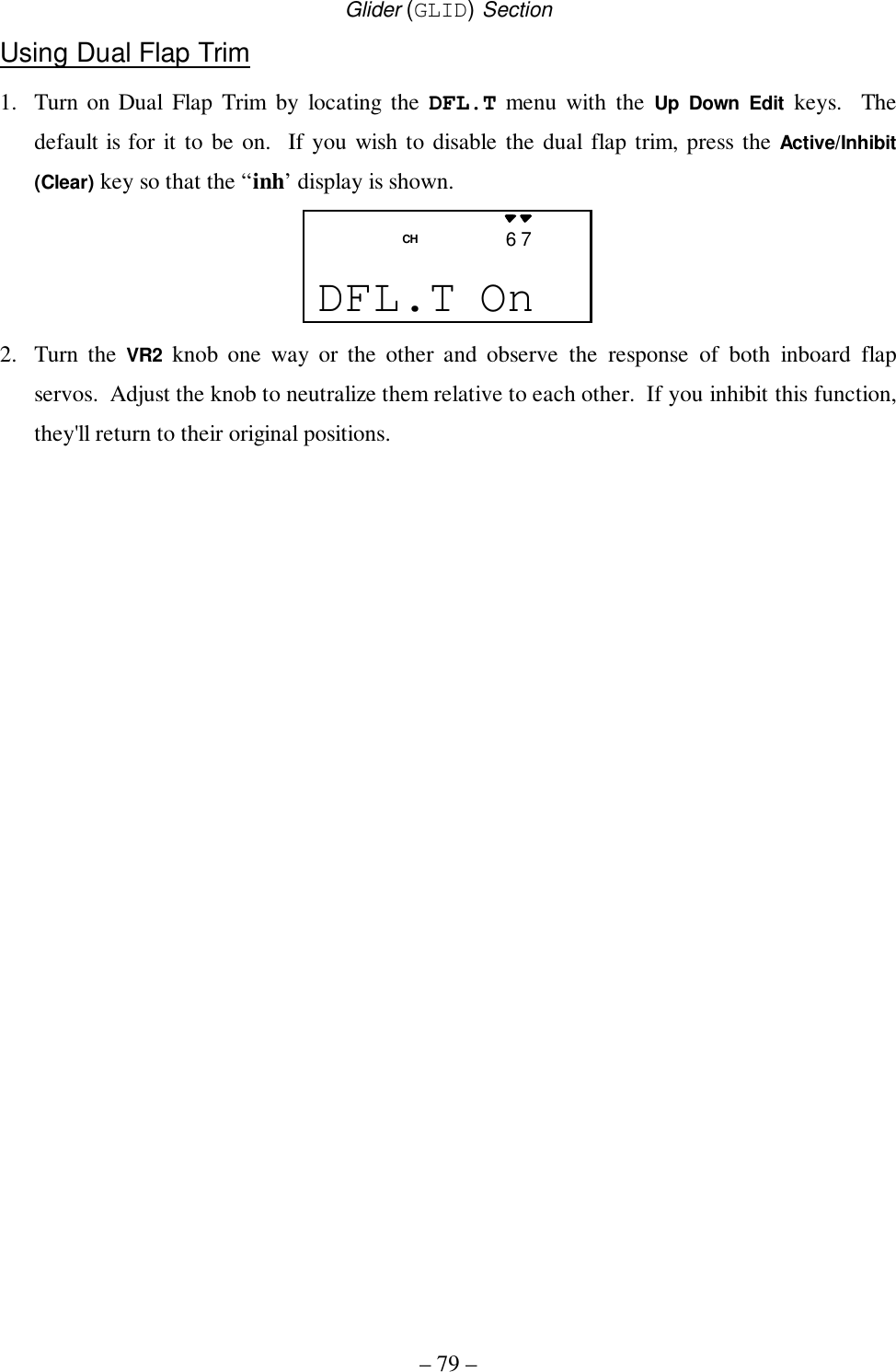
Hitec RCD Inc. R/C of Model Aircraft User Instructions
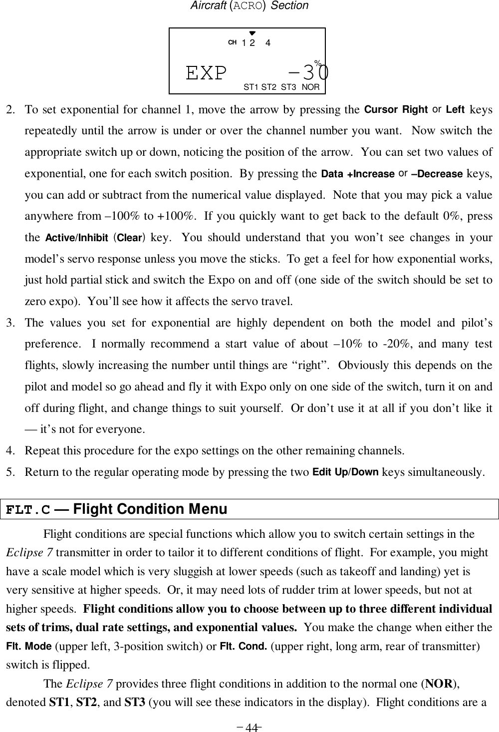
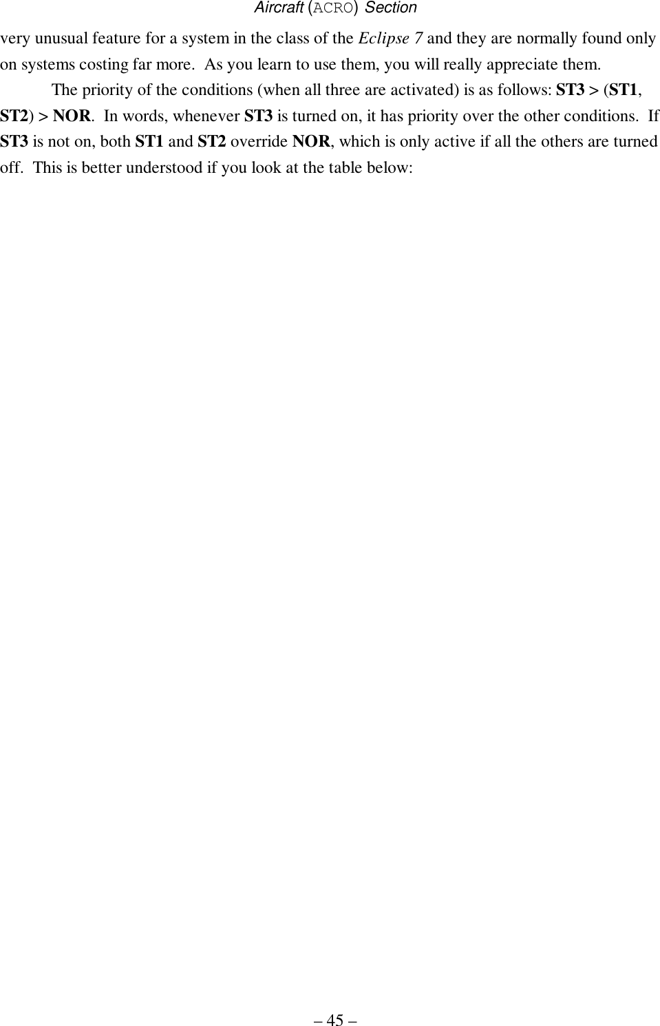
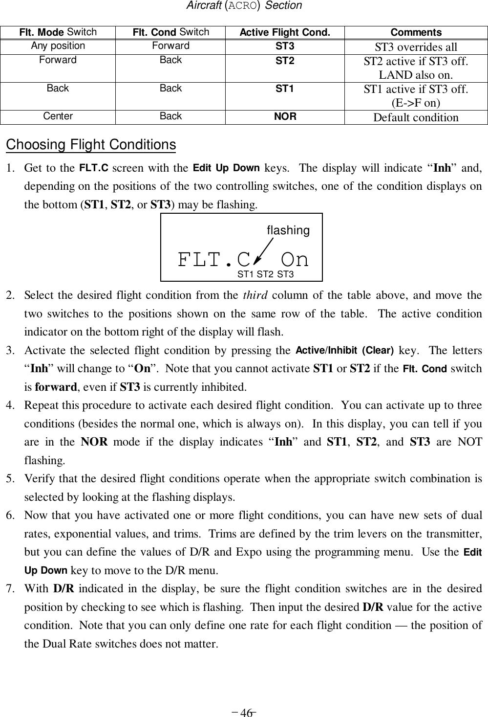
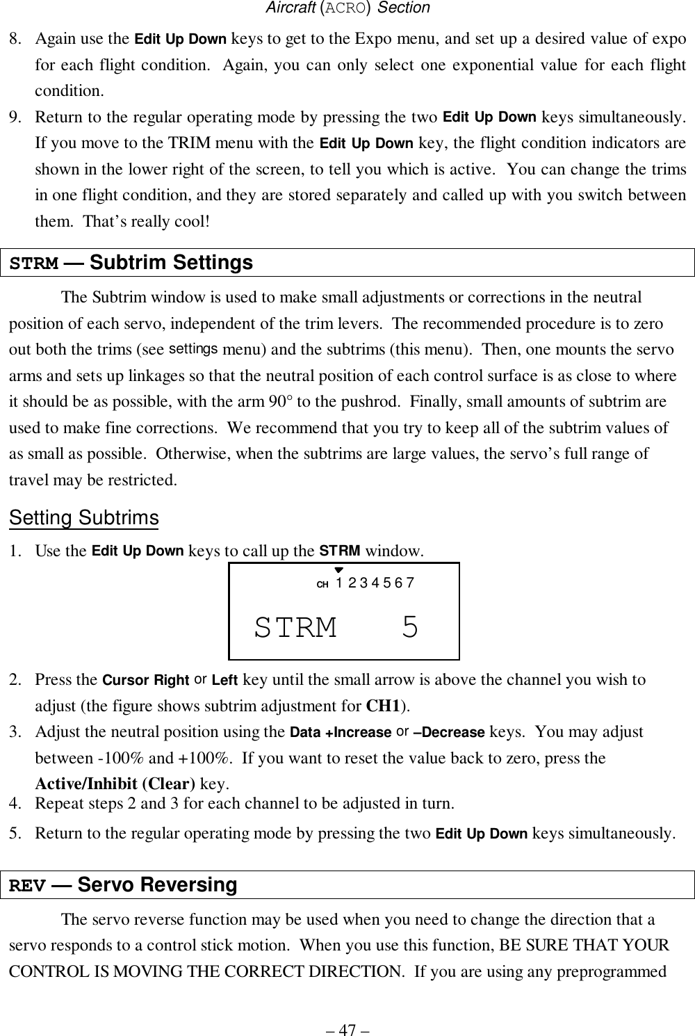
UserManual.wiki
>
Hitec RCD
>
HPF M72 User Manual
User Instructions
Navigation menu
Upload a User Manual
Namespaces
Wiki Guide
HTML
PDF
Info
Views
User Manual
Discussion / Help
Navigation
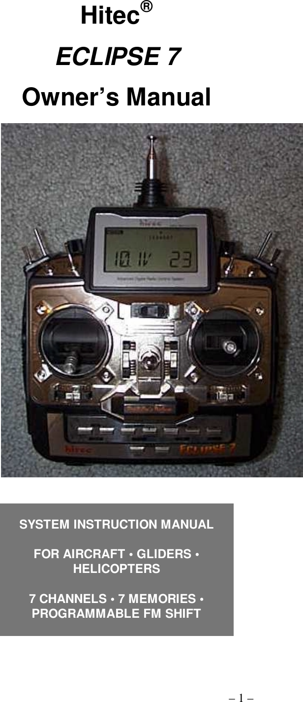


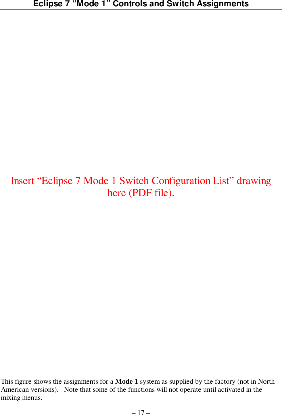

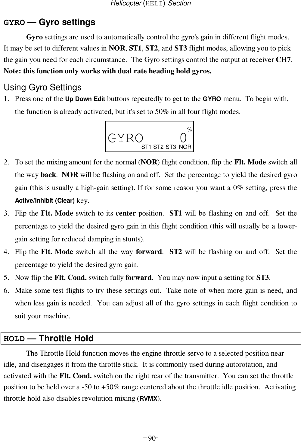
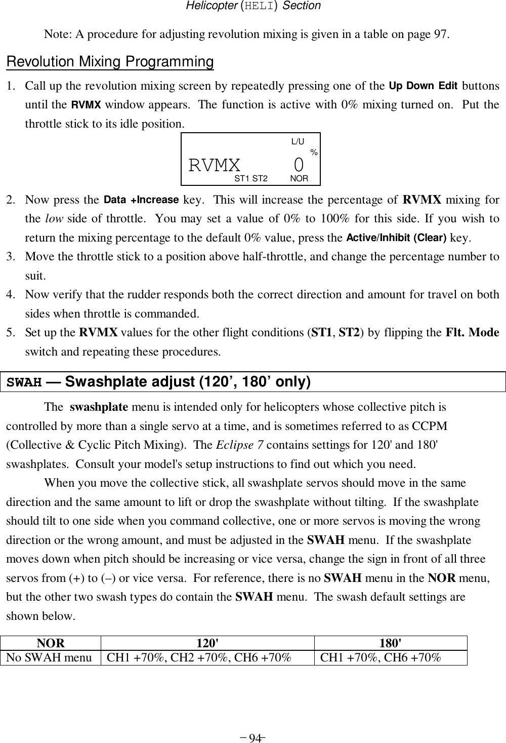
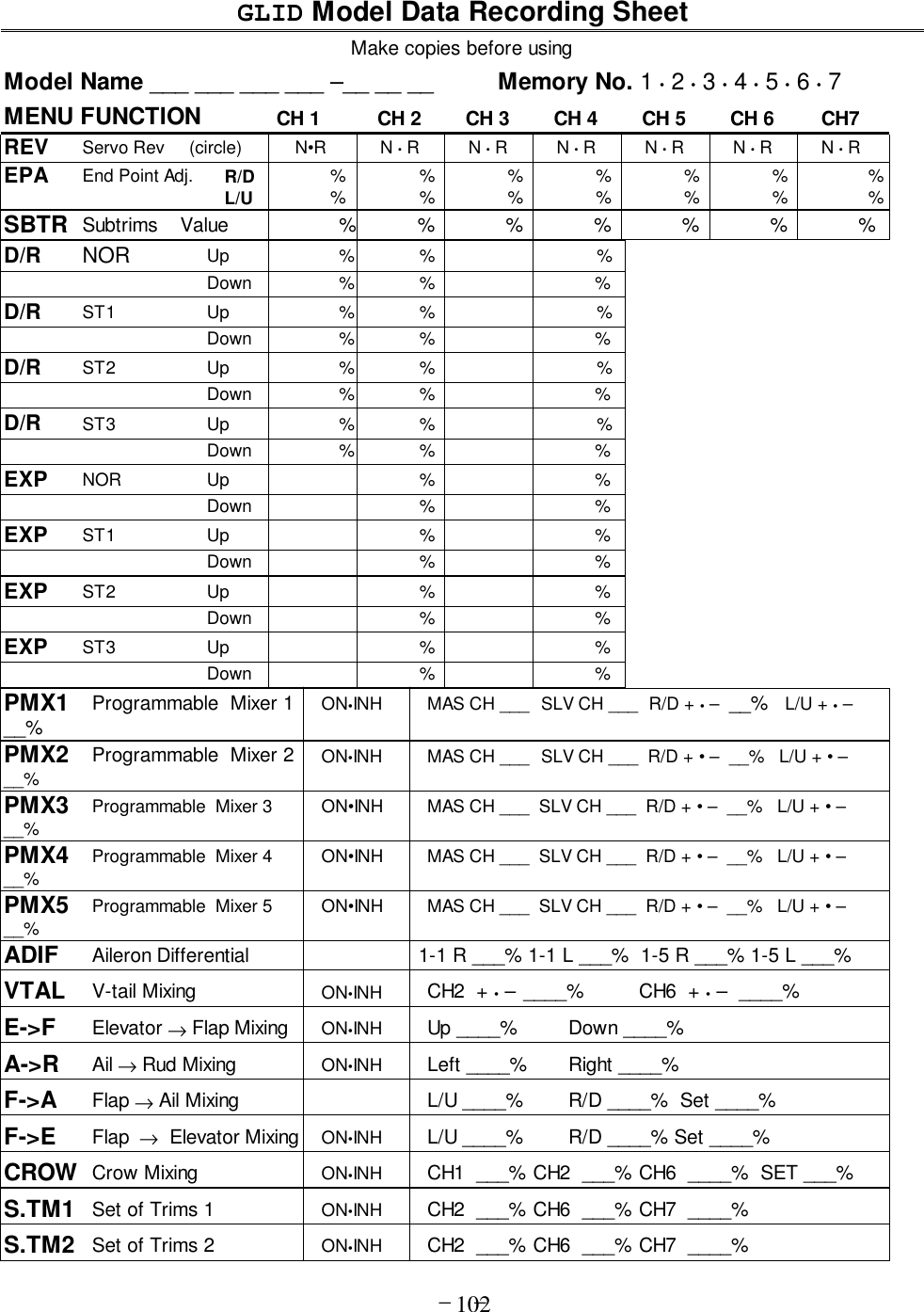
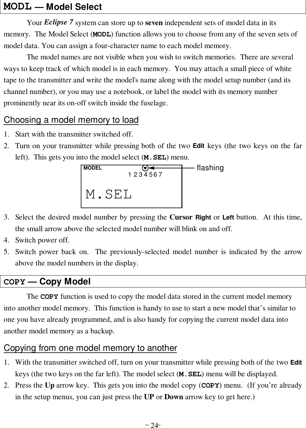
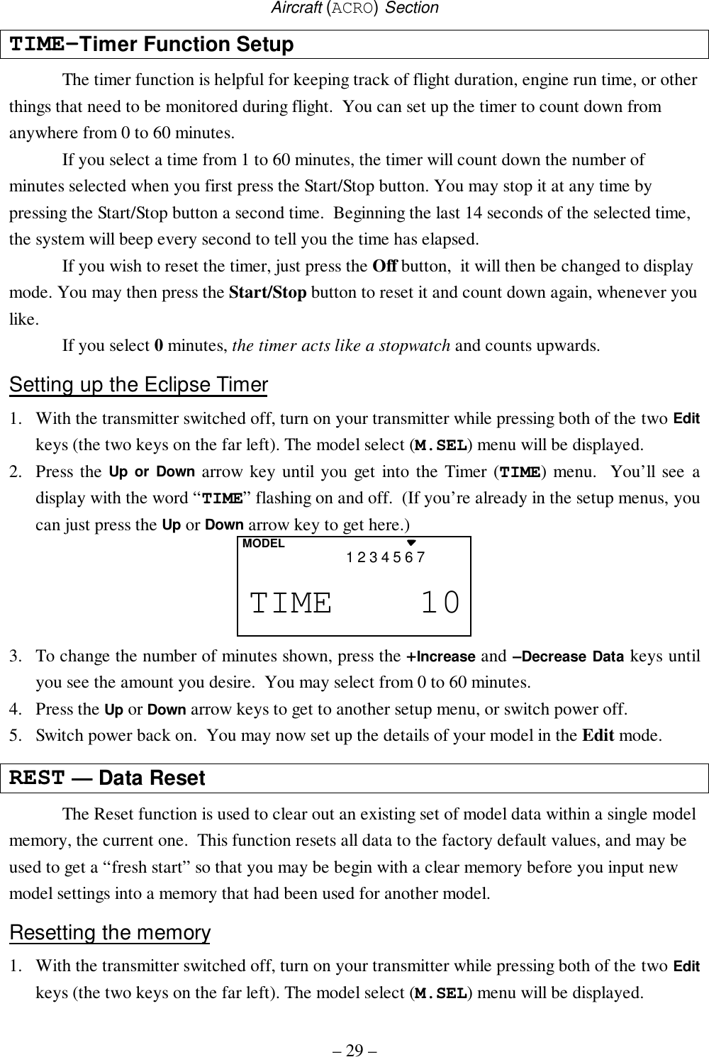
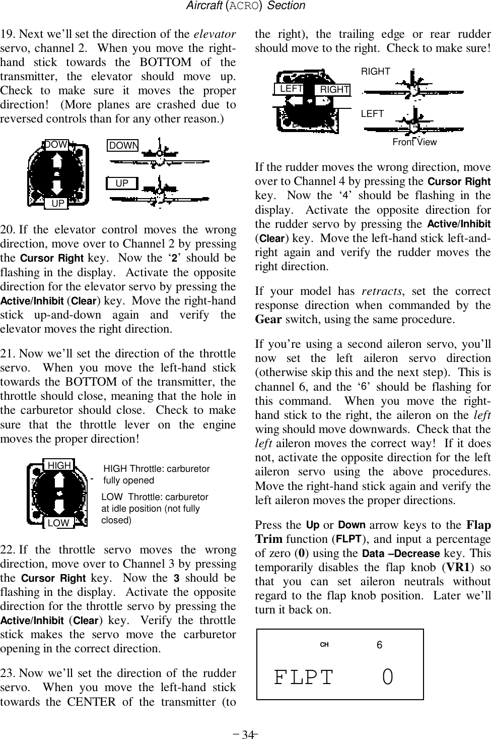
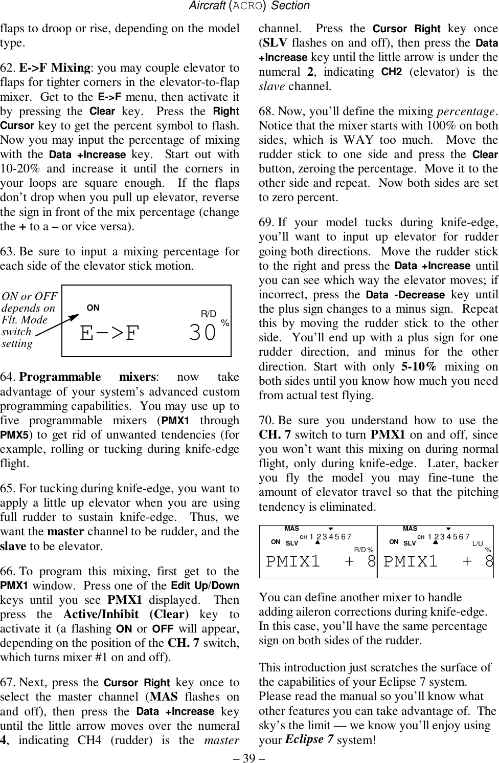
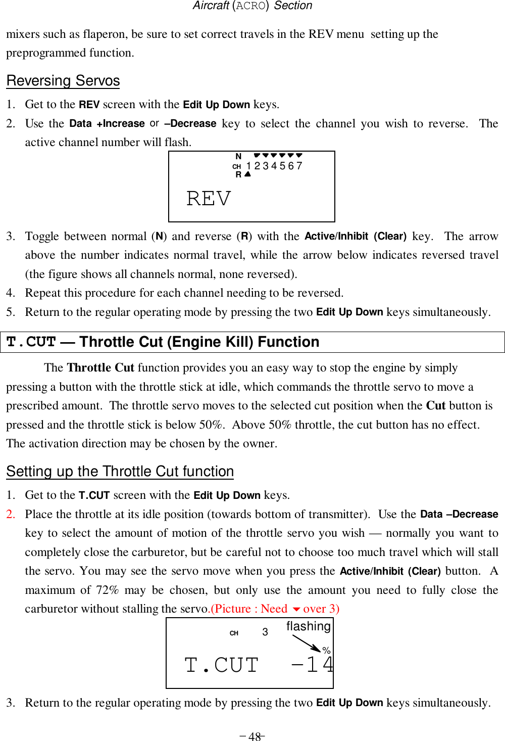
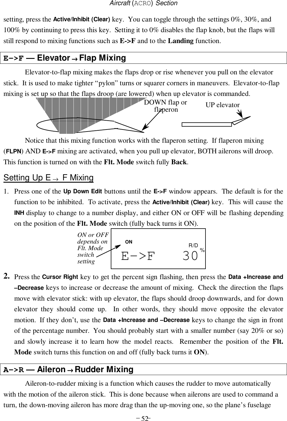
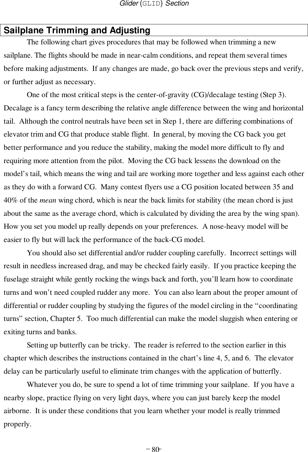
![– –20Transmitter Displays & MessagesWhen you first turn on your transmitter, the first screen shown below appears on the LCDdisplay. Before flying, or even starting the engine, BE SURE that the model numberappearing in the lower right of the display matches the model that you are about to fly! Ifyou don’t, reversed servos and incorrect trims will lead to an immediate crash.You can scroll up and down through the startup screen by pressing one of the two Edit keys(the two keys on the far left). If you press timer or engine cut or lock keys, you go directly tothose functions regardless of the display.Timer DisplayNormal Display ModeVoltage/Timer Display Trim Menu [TRIM]Model Name DisplayStart/Stop keyOff keyEngine CutCut keyThrottle LockLock key10.3V 1294213567MODEL This screen appears at startup. The model memory number isshown by the small down-arrow. Battery voltage is shown inthe bottom left, and operating time is on the lower right. Youcan reset the operating time display by hitting the Clear button(the one on the farthest right). Do this after each charge to keeptrack of your operating time on a single charge.TRIM 0CH%ST14216ST2 ST3 NORPressing the Up button gives the Trim display (differentnumbers may appear depending on the model type). To seewhere the trim for a certain channel is, you have to move it! Besure to move it back to where it was. Note that the CH3 trimonly moves downward, so if you need more engine RPM, set upidle with the trim at –25% so you can increase it if needed.EAGL- 14213567MODELPressing the Up button again gives the Model Name display. Ifyou’ve named your model, it will appear here so you can besure you have recalled the correct memory. If you do not namethe model, you'll have to remember which model memory it's](https://usermanual.wiki/Hitec-RCD/HPF-M72/User-Guide-140921-Page-20.png)
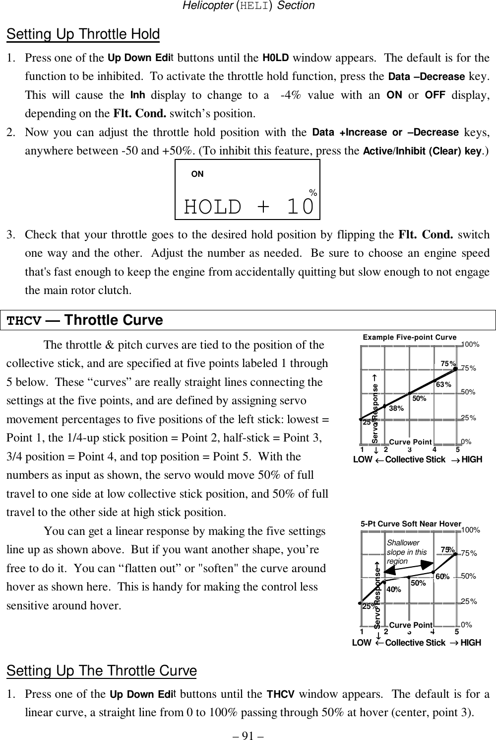
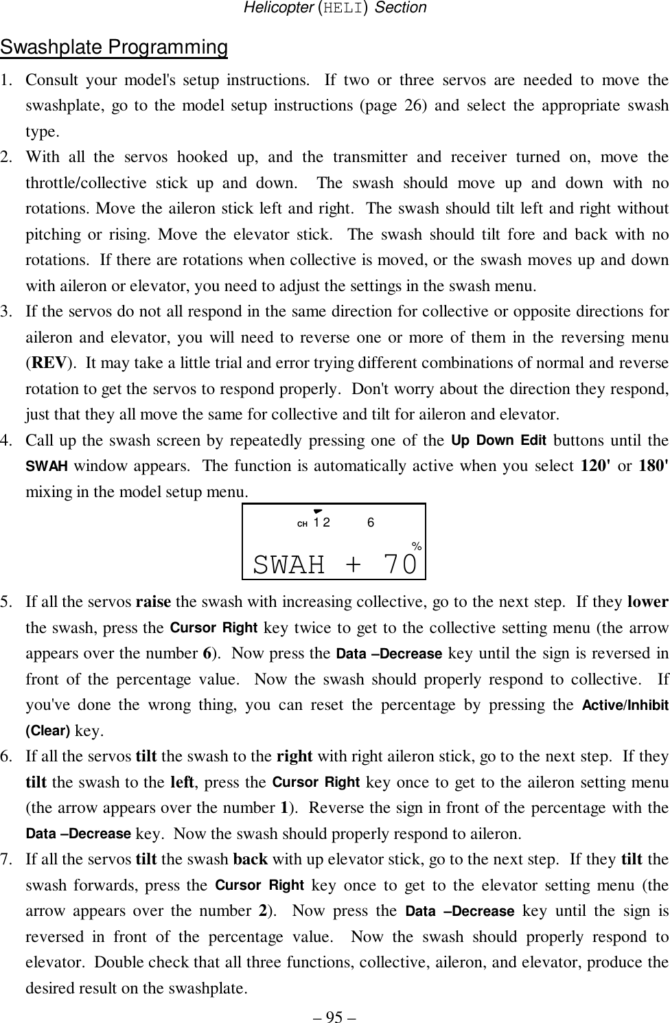
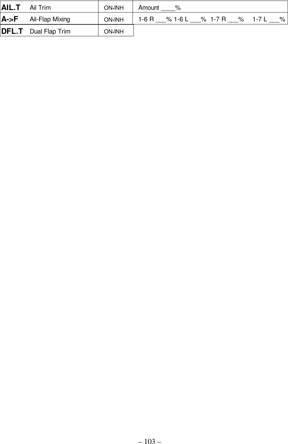
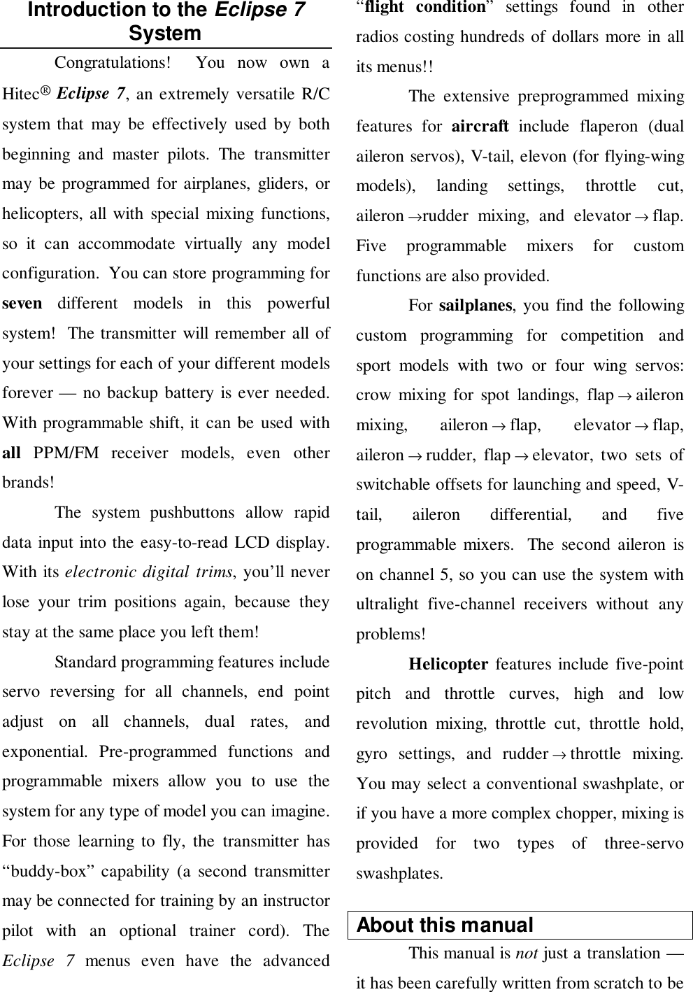
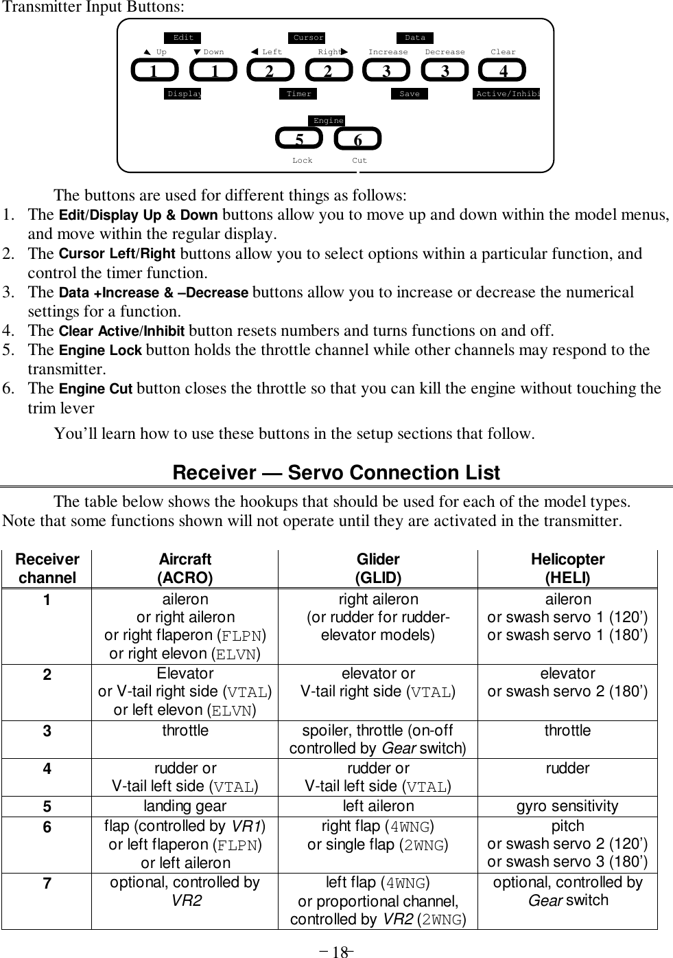
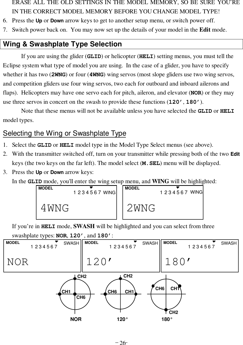
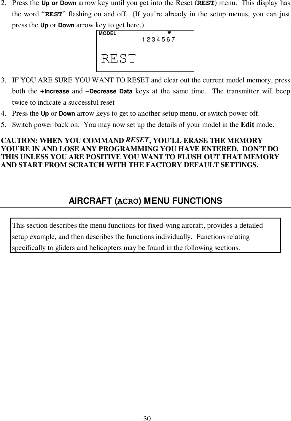
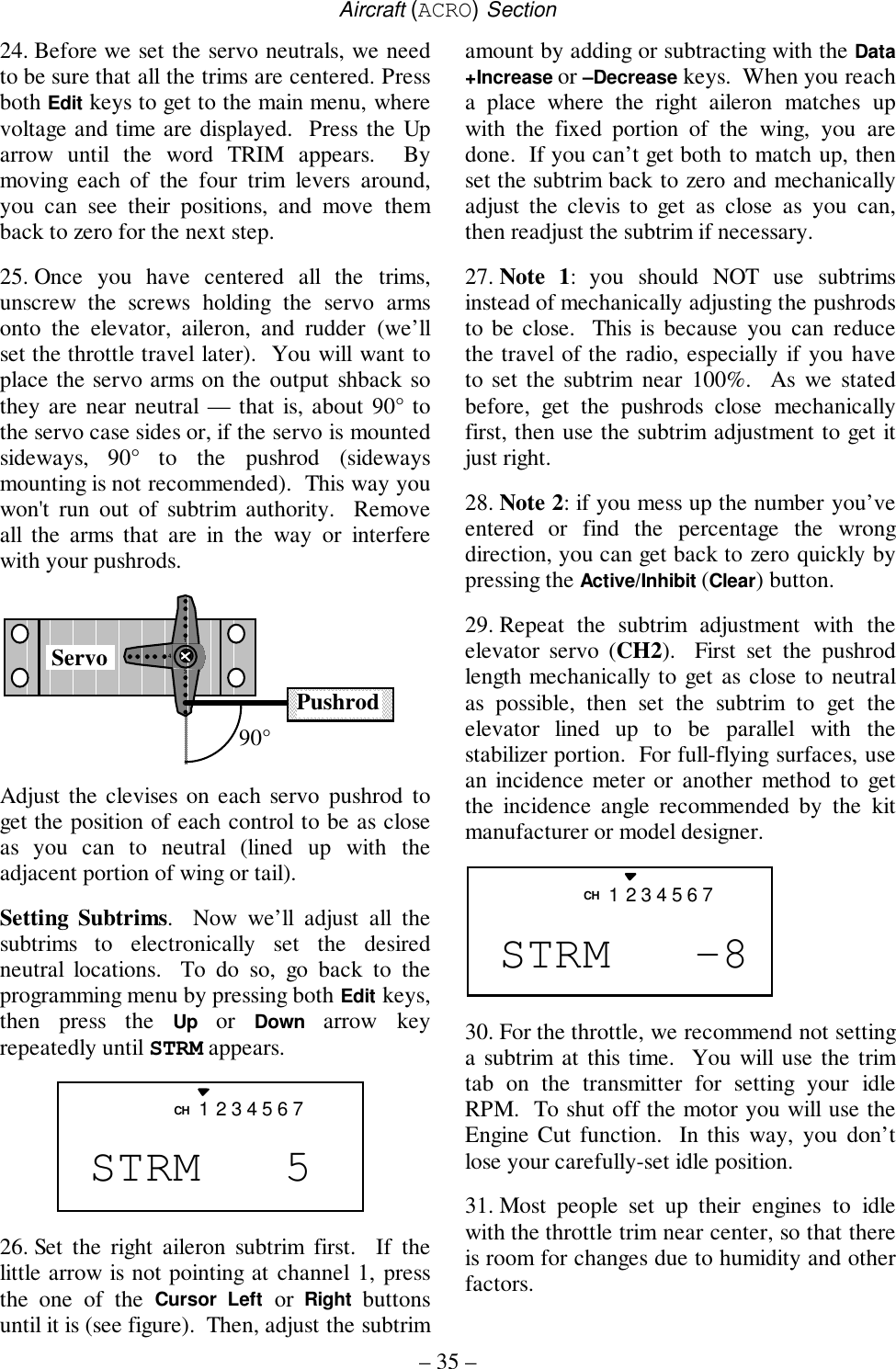
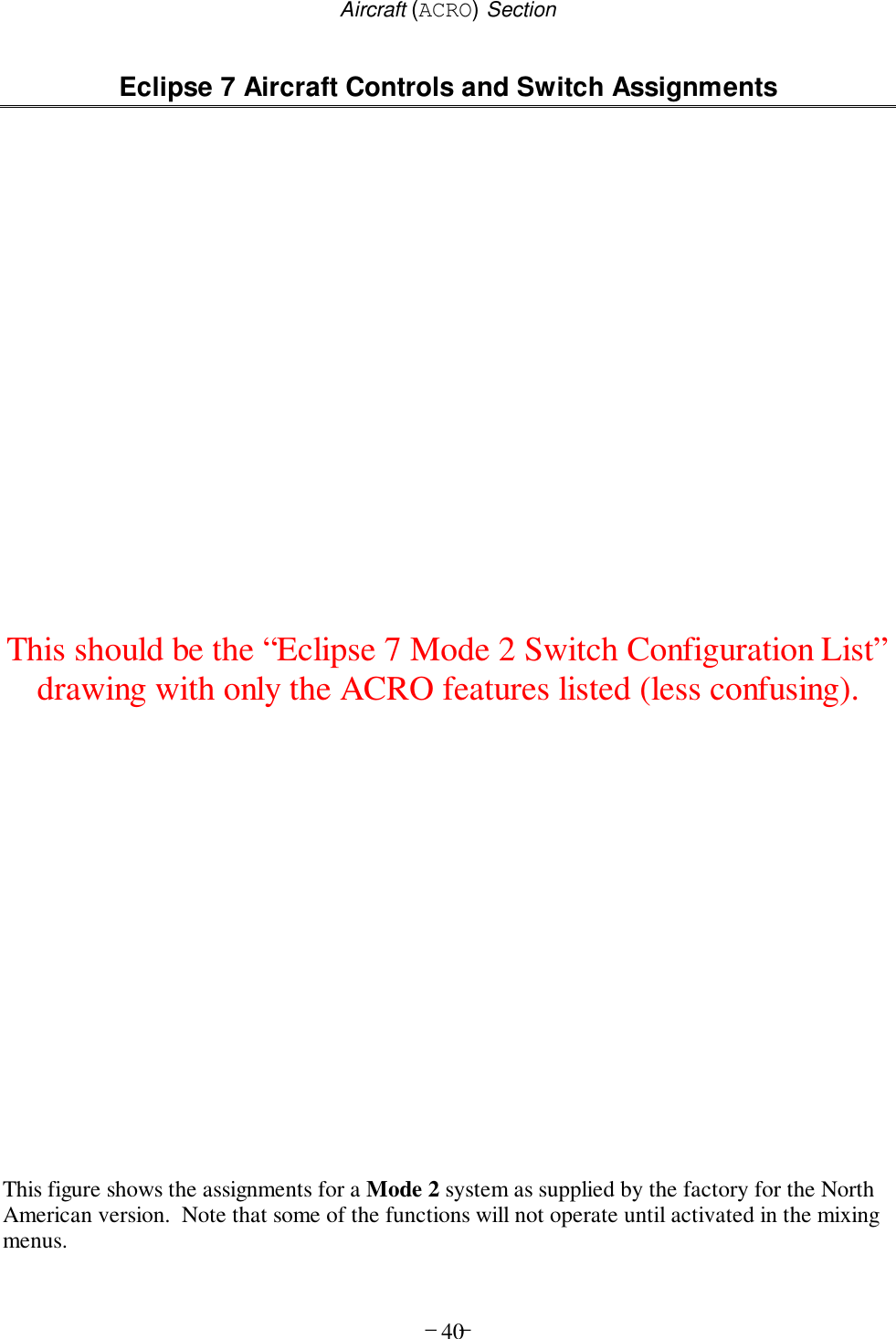
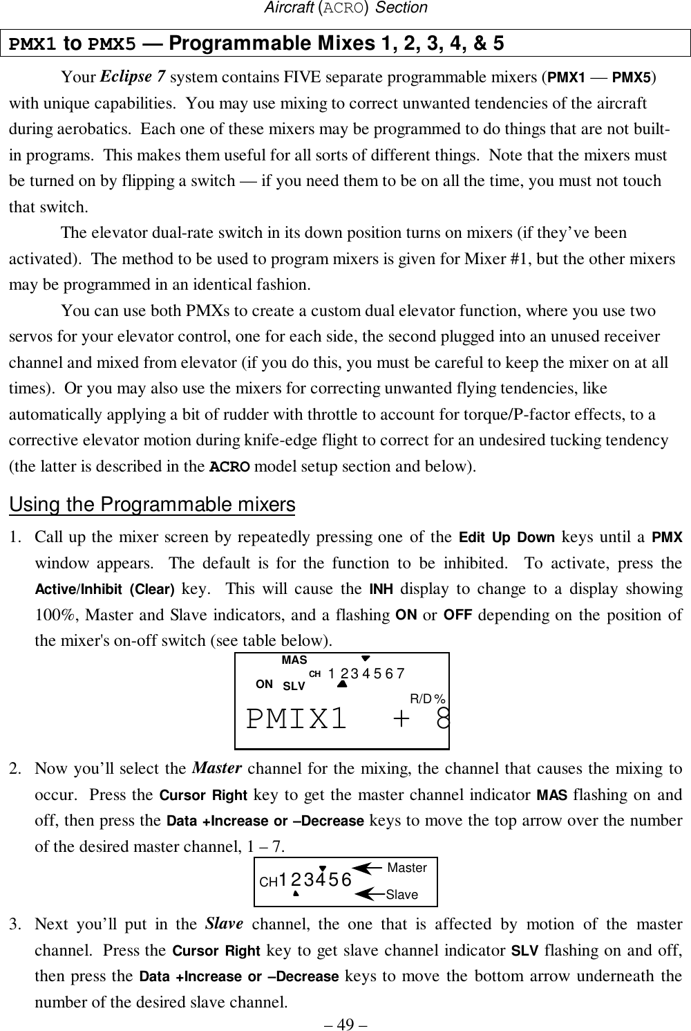
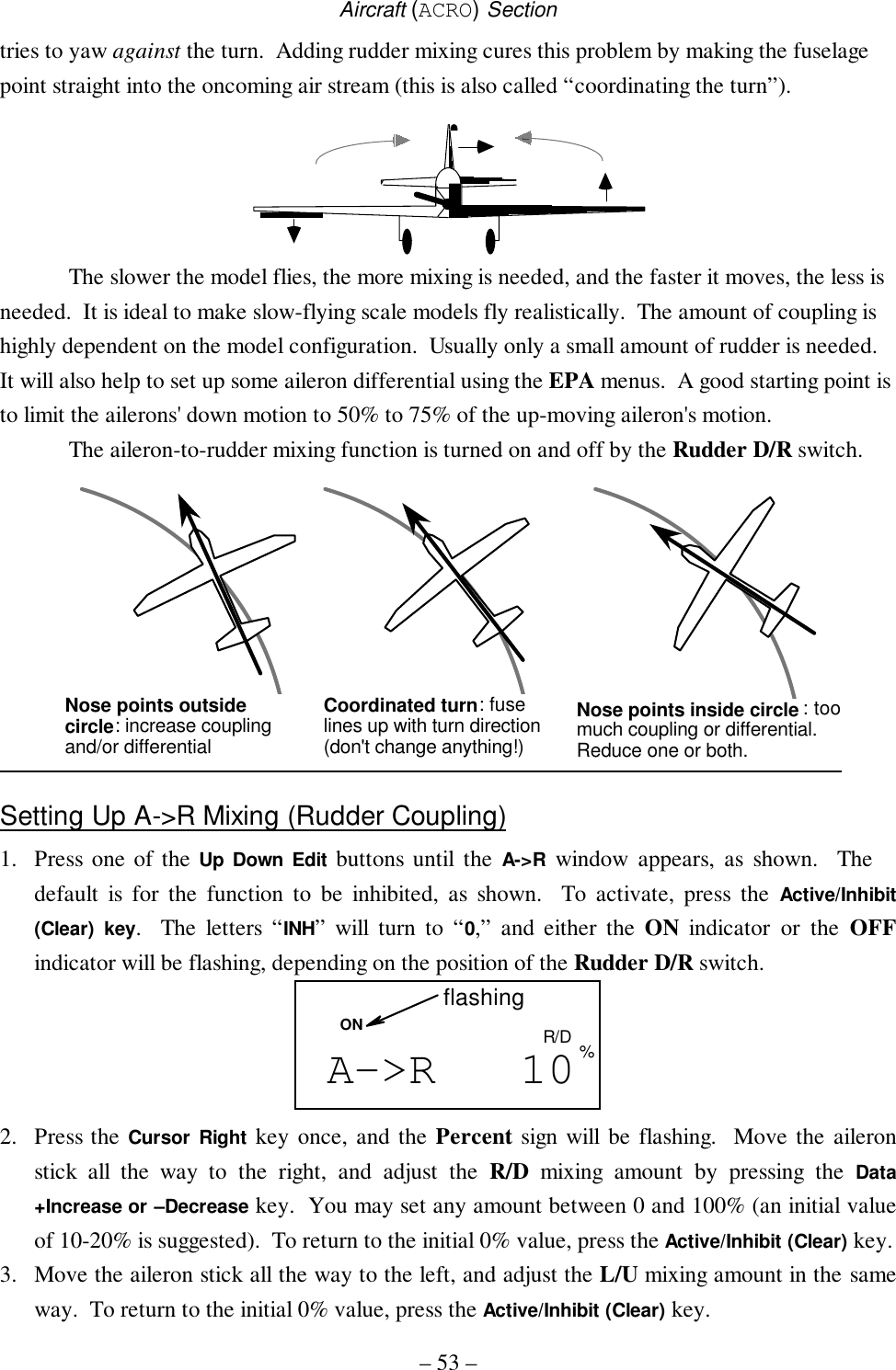
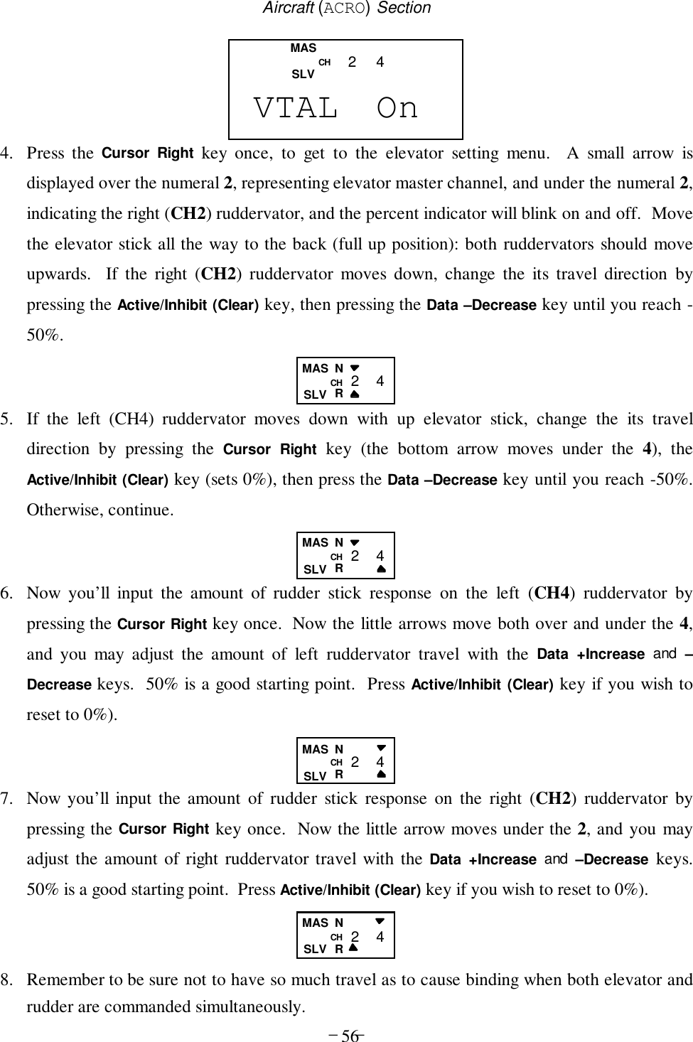
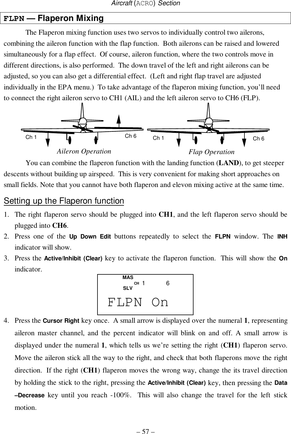
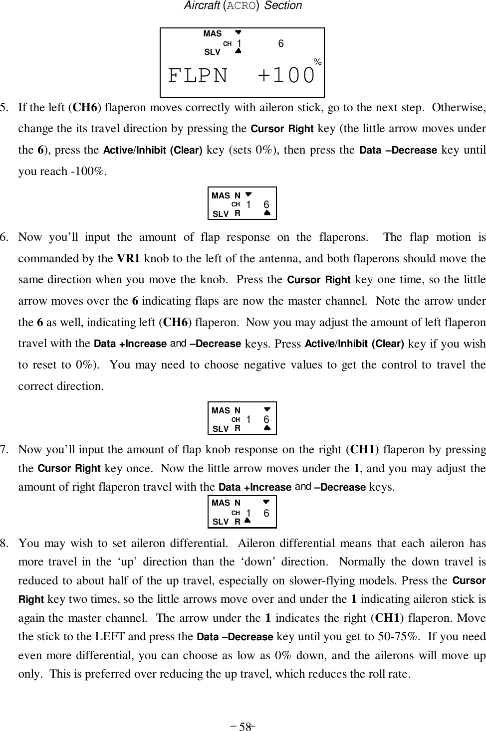
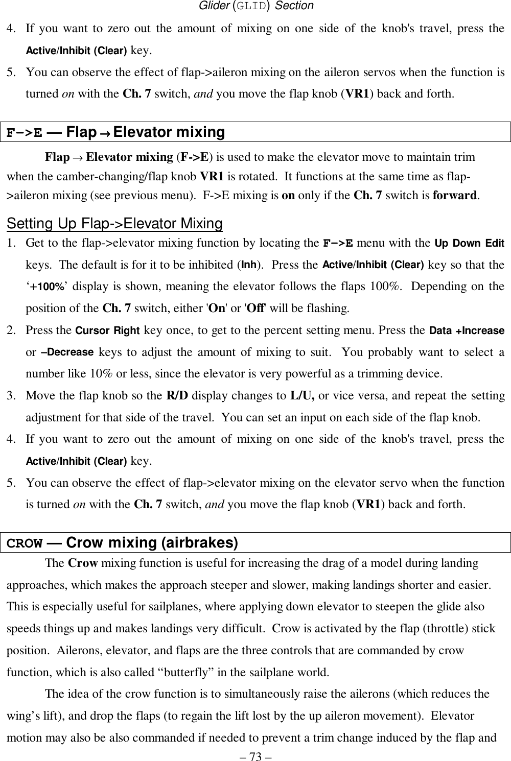
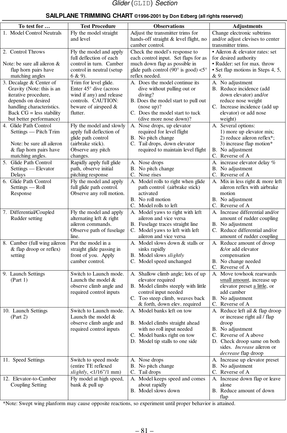
![Aircraft (ACRO) Section– 23 –Model Setup FunctionsThis section describes the model setup functions that are used to choose all of theoperating features of a particular model memory. These functions are used to select themodel memory, the model type (from airplanes, gliders, and helicopters), set thestopwatch, and other useful functions. These functions are used to set up a new model ora new model memory, to switch between memories, and to change transmit shift..Map of Basic Menu Functions...............(see right)M.SEL..... Model select .......................................24COPY ....... Data Copy ..........................................24ACRO ....... Acrobatic model mode .......................25HELI ....... Helicopter model mode ......................25GLID ....... Glider model mode.............................252WNG ....... Two Servo Wing (GLID only)............264WNG ....... Four Servo Wing (GLID only) ...........26NOR.......... Normal swashplate (HELI only) ........26120’ ....... 120’Swashplate (HELI only)..............26180’ ....... 180’Swashplate (HELI only)..............26**** ....... Model Name (four letters +up to three numbers) ..........................27SFT.N..... Transmit Shift.....................................28TIME ....... Timer setup.........................................29REST ....... Reset Memory....................................29 Model Select [M.SEL]Copy Model [COPY]Model Name [ABCD-199]Swashplate type (HELI only) [NOR ] [120’ ] [180’ ]Timer Setup [TIME XX]Reset Memory [REST ]Power On While Pressing both Edit/Display keysShift Dir. [SFT.N] [SFT.P]Model Type [ACRO], [HELI], [GLID]Wing Type (GLID only) [4WNG], [2WNG]](https://usermanual.wiki/Hitec-RCD/HPF-M72/User-Guide-140921-Page-23.png)
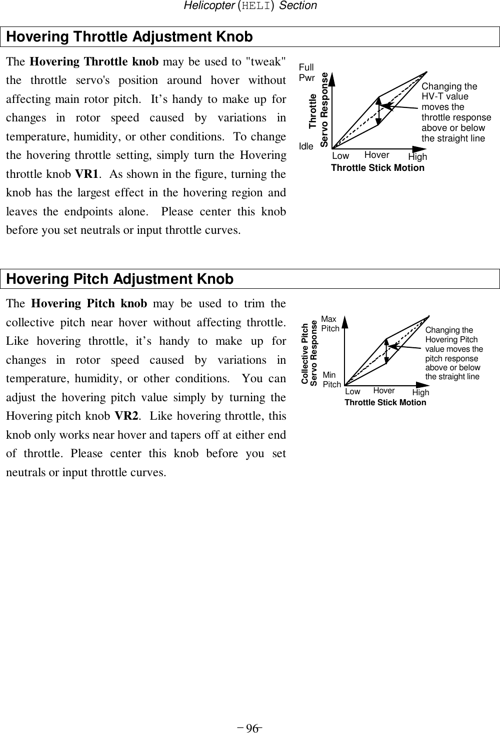
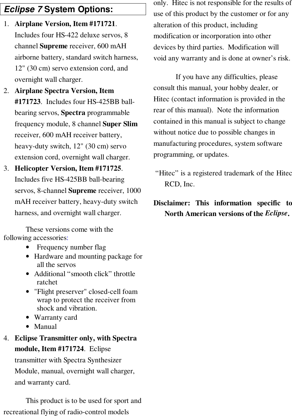
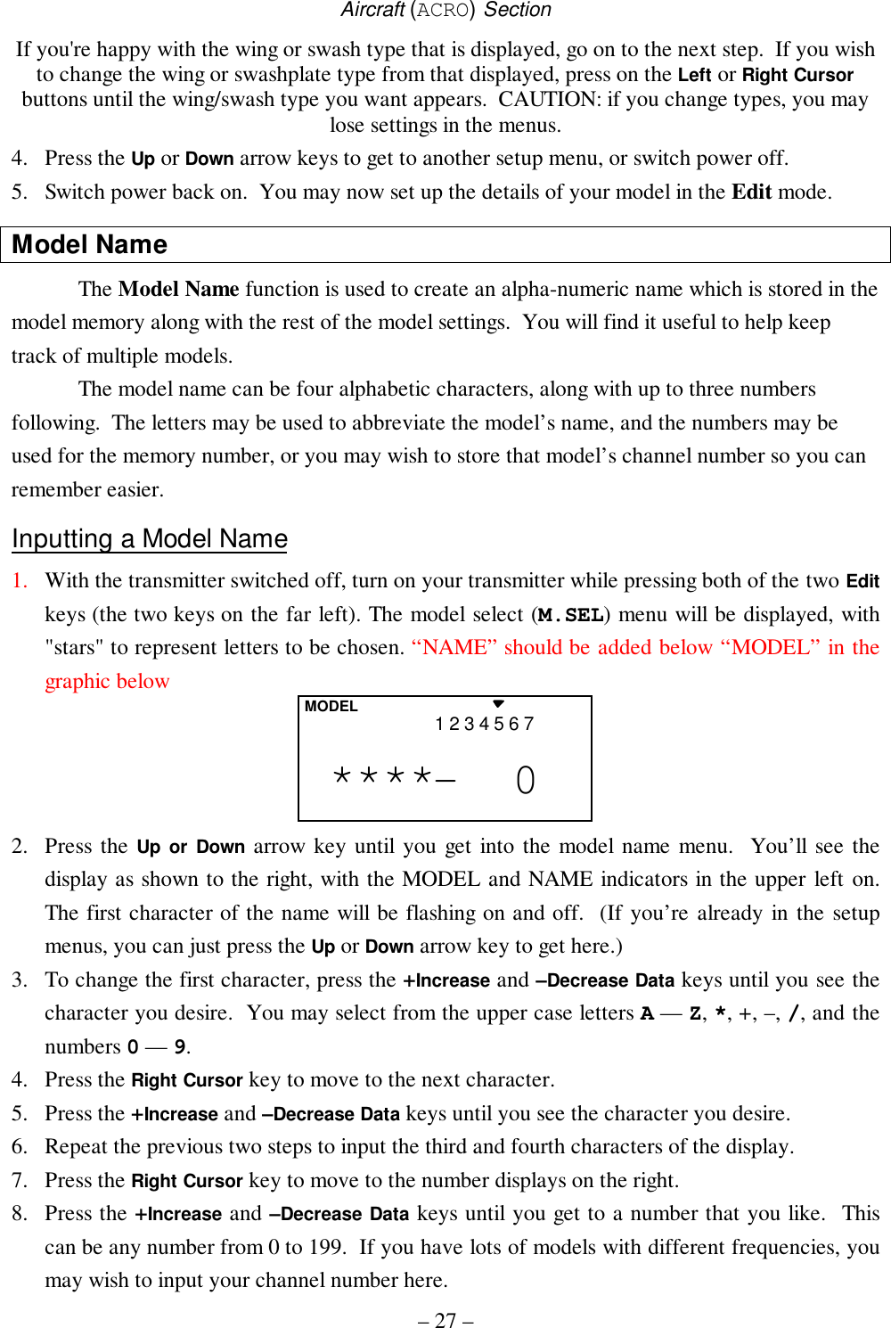
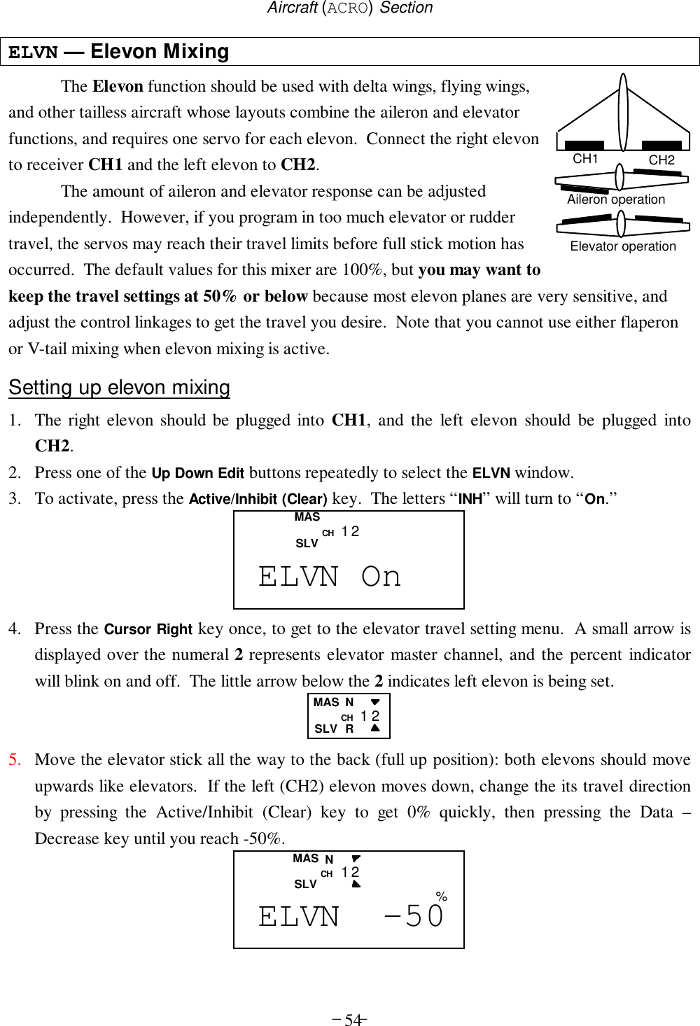
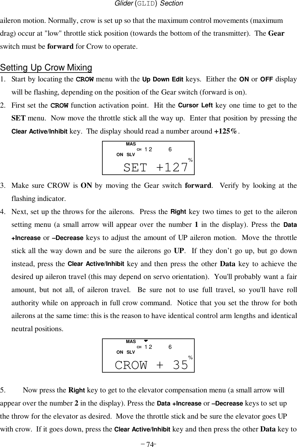
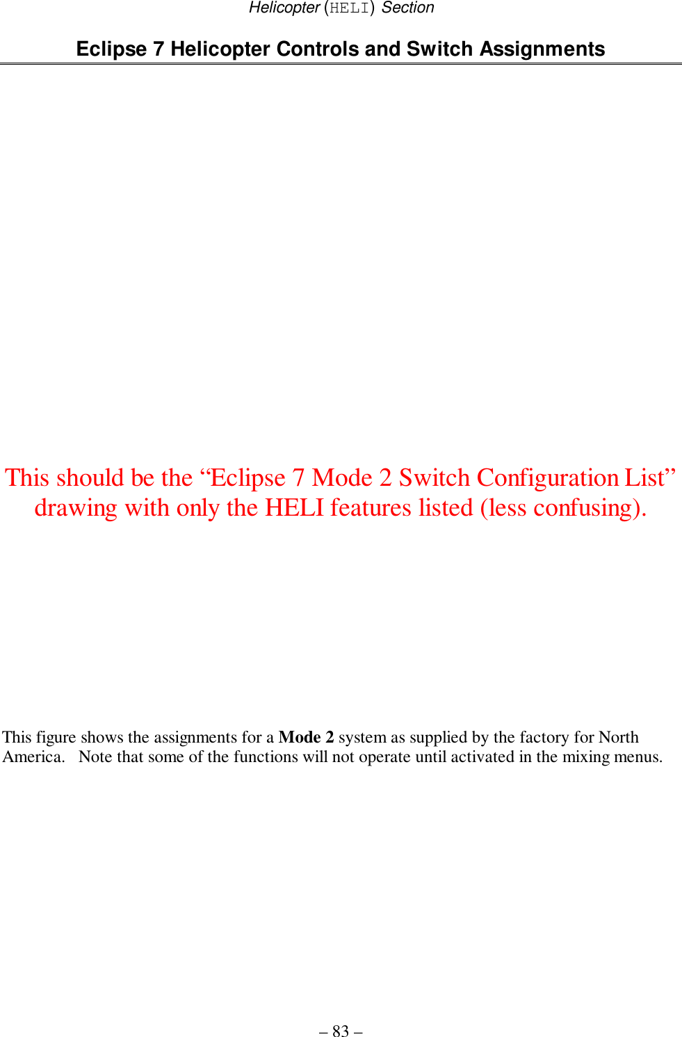
![Aircraft (ACRO) Section– 25 –COPY4213567MODEL Current No.SLVMASDestination (flashing)3. The source model memory (the memory that will be duplicated) is the current one, indicatedby the fixed upper arrow. To select your destination model number, press the Left or RightCursor keys. The selected destination memory number is shown by the flashing triangleunder it.4. Press the +Increase and –Decrease Data keys at the same time. The transmitter beeps twicerapidly, indicating the copy has been completed. THIS WILL ERASE ALL THE OLDSETTINGS IN THE SLAVE MODEL MEMORY, SO BE SURE YOU’RE IN THECORRECT MODEL BEFORE YOU COPY MODEL!5. Switch power off.6. Switch power back on. If you wish to go to the newly-saved memory, repeat step 1.ACRO, HELI, GLID — Model Type SelectThis function is used to select the type of model to be programmed in the current modelmemory. You may select from aircraft (ACRO), gliders (GLID), and helicopters (HELI). If youselect glider or helicopter types, you will need to set the wing type (for a glider) or the swash type(for a helicopter). These settings are covered below.Selecting the Model Type1. With the transmitter switched off, turn on your transmitter while pressing both of the two Editkeys (the two keys on the far left). The model select (M.SEL) menu will be displayed.2. Press the Down arrow key. This gets you into the type select menu. The current model typewill be flashing on and off. (If you’re already in the setup menus, you can just press the Up orDown arrow key to get here.)ACRO4213567MODELflashing GLID4213567MODELflashing HELI4213567MODELflashing3. If the model type you want is displayed, you’re done. [If you wish to change the wing typeor swash type in the GLID and HELI model settings, see the sections below.]4. If you wish to change the model type from that displayed, press on the Left or Right Cursorbuttons until the model type you want, either ACRO, GLID, or HELI, appears.5. To select your desired model type, press both the +Increase and –Decrease Data keyssimultaneously. Two beeps tell you that the new model type is now registered. THIS WILL](https://usermanual.wiki/Hitec-RCD/HPF-M72/User-Guide-140921-Page-25.png)
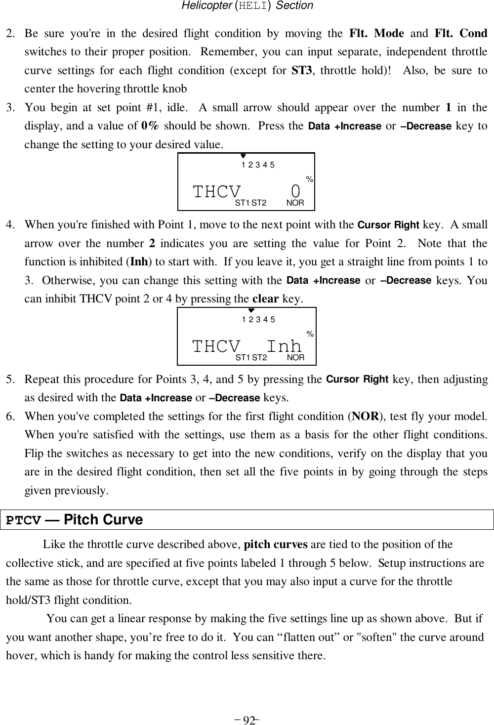
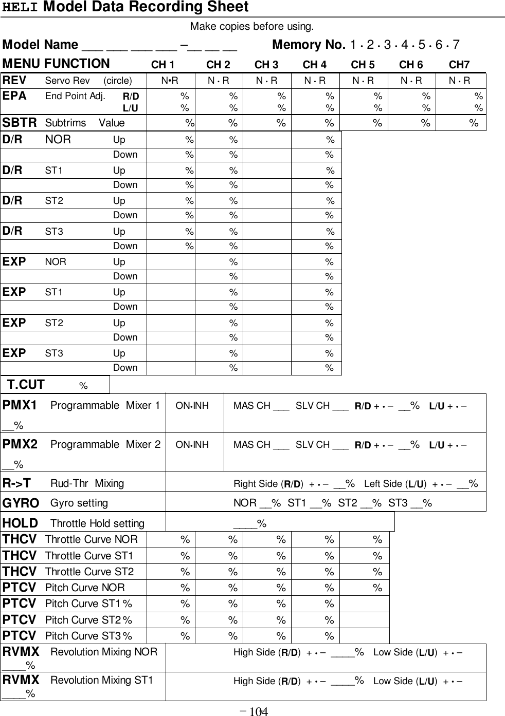
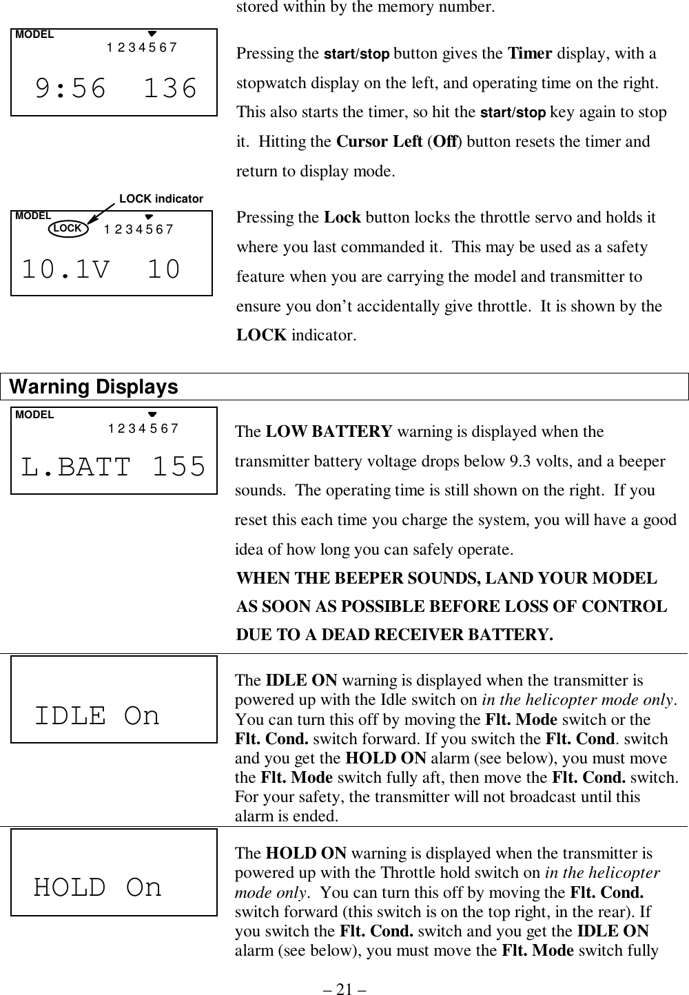
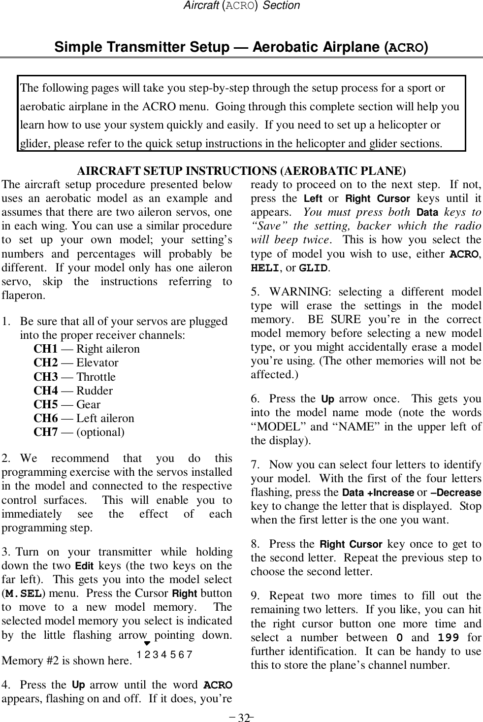
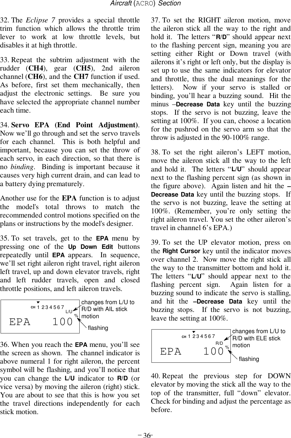
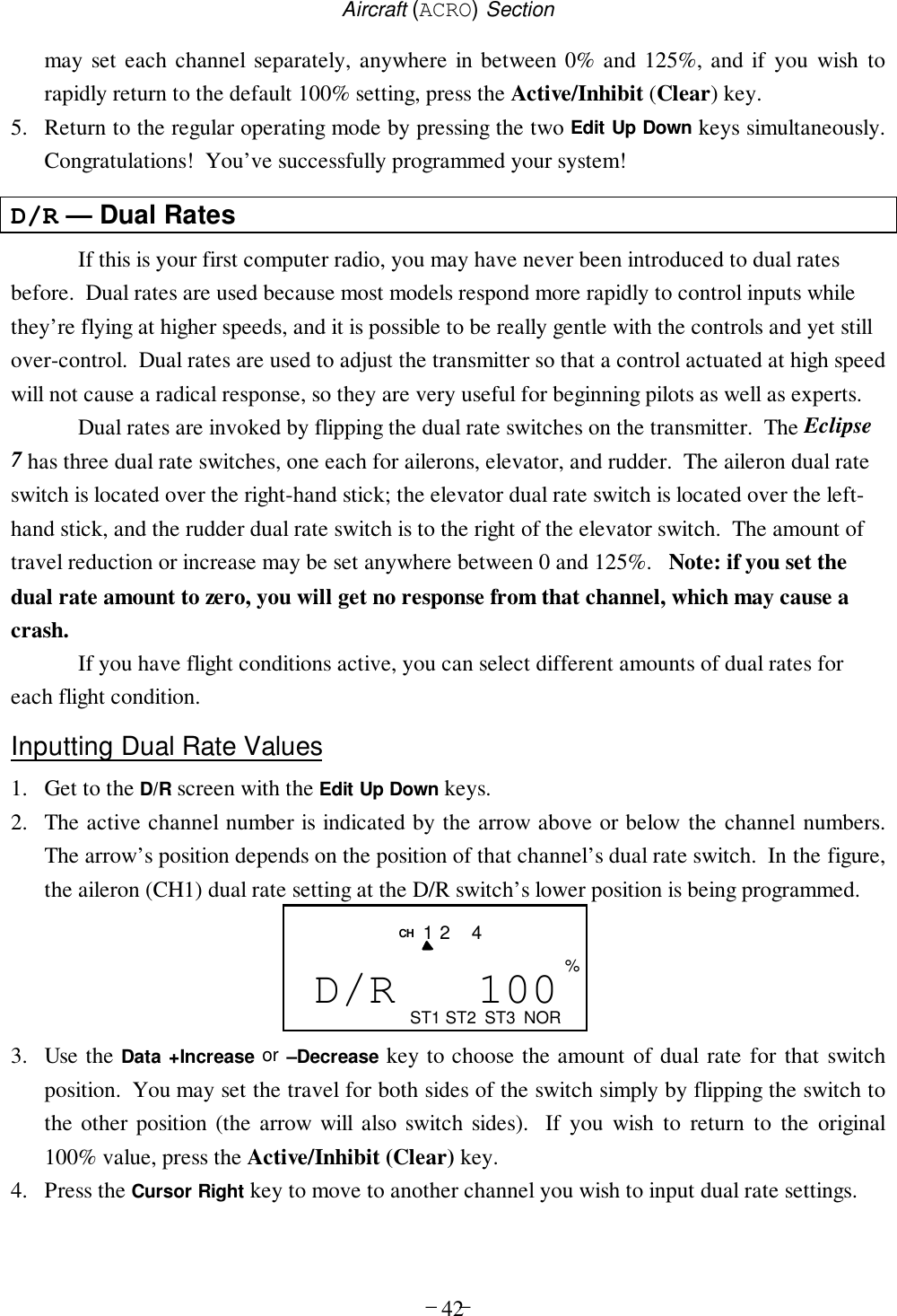
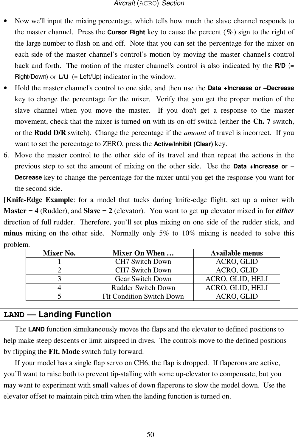
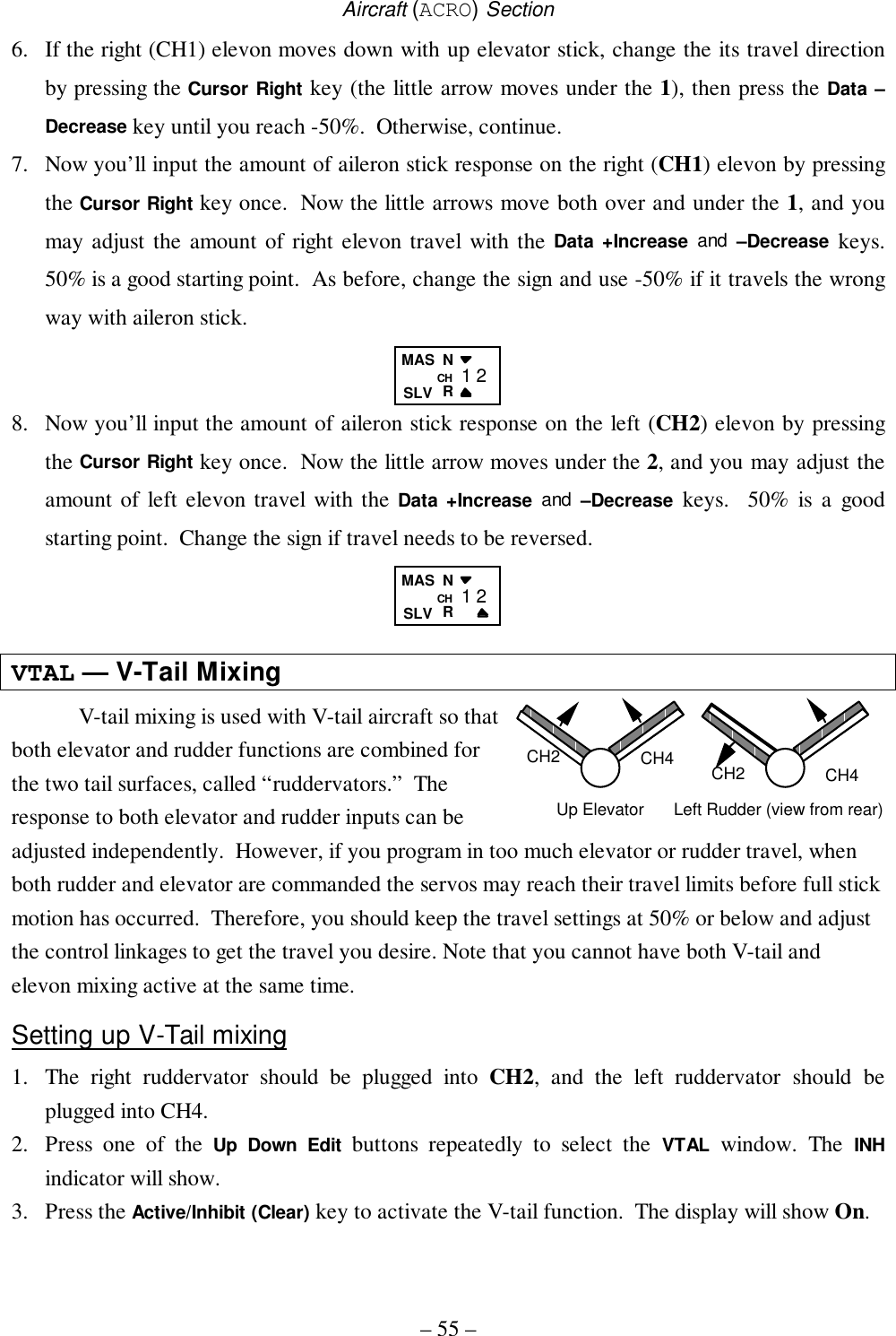
![Aircraft (ACRO) Section– 31 – ACRO Functions Map.......................................... (see right)Simple Aerobatic Airplane Transmitter Setup...............32EPA............End Point Adjust (servo travels)......................41D/R............Dual Rates........................................................42EXP............Exponential Settings.........................................43FLT.C........Flight Condition Select.....................................44STRM .........Subtrim.............................................................47REV............Servo Reverse ..................................................47T.CUT ........Throttle Cut (engine shut off) ..........................48PMX1-5......Programmable Mixer #1 – #5 (five total) ........49LAND .........Landing function settings.................................50FLPT .........Flap trim...........................................................51E->F .........Elevator →Flap mixing.....................................52A->R .........Rudder Coupling..............................................52ELVN .........Elevon mixing (tailless models) .......................54VTAL .........V-tail mixing.....................................................55FLPN .........Flaperon (combined flaps & ailerons)..............57Aircraft Trimming Chart .................................................60Dual Rate Set [D/R]End Point Adjust [EPA]Press both Edit/Display keysAil → Rud Mix [A-R]Flap Trim [FLTR]Landing [LAND]Elev → Flap Mix [E-F]Prog. Mix 1-5 [PMX-]Flight Cond. [FLT.C]Elevon Mix [ELVN]V-Tail Mix [VTAL]Exponential [EXP]Sub-Trims [STRM]Servo Reversing [REV]Throttle Cut [T.CUT]Flaperon Mix [FLPN]Normal Display ModeVoltage/Timer Display](https://usermanual.wiki/Hitec-RCD/HPF-M72/User-Guide-140921-Page-31.png)
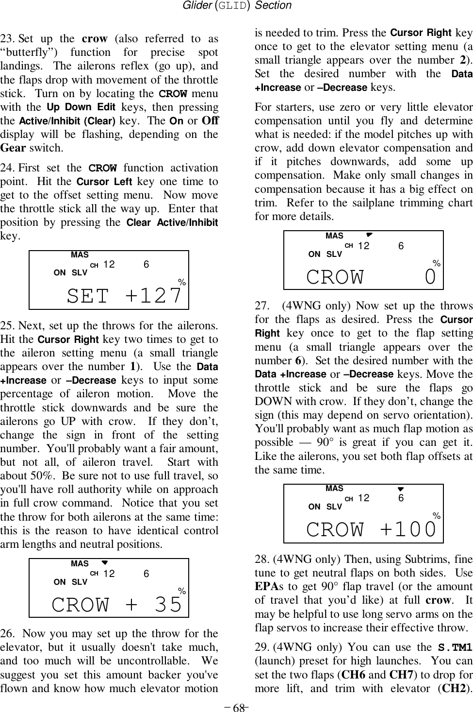
![Aircraft (ACRO) Section– 37 –41. To set the throttle position at IDLE, firstreturn to the regular display and set thethrottle trim to +25%. Then go back to theEPA menu and press the Right Cursor keyuntil the arrow moves over channel number 3.Now move the throttle stick all the way to thetransmitter bottom and hold it. The letters“L/U” should appear next to the flashingpercent sign. Listen for a buzzing sound toindicate servo stalling, and hit the –DecreaseData key until the buzzing stops. Change thesetting to nearly — but not completely —close the throttle (engine idle). Later you mayincrease or decrease this number so you can’taccidentally shut off the engine using the trimtab.42. To set the FULL throttle position, movethe throttle stick all the way to the transmittertop and hold it. The letters “R/D” shouldappear next to the flashing percent sign.[Notice that the Eclipse 7 transmitter thinks ofthrottle stick positions to the reverse of theway it seems, in that with the throttle stickfully forwards — “up” towards the transmittertop, is the Down position.] Listen for abuzzing sound to indicate the servo is stalling,and hit the –Decrease Data key until thebuzzing stops. If the servo is not buzzing,leave the setting at 100% or change yourlinkage as necessary to fully open the throttle.43. To set the RIGHT rudder motion, press theRight Cursor key until the indicator movesover channel 4. Now move the left stick allthe way to the transmitter right and hold it.The letters “R/D” should appear next to theflashing percent sign. Listen for a buzzingsound to indicate the rudder servo is stalling,and hit the Data –Decrease key until thebuzzing stops. If the servo is not buzzing,leave the setting at 100%. You may wish toincrease or decrease this number depending onhow strongly the model reacts when therudder is deflected. Now move the stick to theleft side, and repeat the setting procedure forleft rudder.44. In the same manner as described above, besure to set EPA values for channels 5 (landinggear) and 6 (second aileron), if you haveeither.45. If you wish to have the flaps operate withthe CH6 knob, go back to the FLPT menu andinput a number greater than zero. Adjust thenumber to get the desired amount of flaptravel as you turn the knob.FLPT 20CH 646. If you wish to have differential ailerontravel, this can be done in the flaperon menu.First, we’ll reduce the down travel on the rightaileron. Press the Right Cursor key until thelittle triangles are both above and below thenumeral 1. Hold the aileron stick to the leftand press the –Decrease Data key until thenumber is smaller. 50-75% is a good startingpoint. Watch to be sure you’re setting thedown travel on the right aileron.47. Next, we’ll reduce the down travel on theleft aileron. Press the Right Cursor key untilthe little triangle moves below the numeral 6(the second aileron; the upper triangle shouldstay over the number 1). This time, hold theaileron stick to the right and press the –Decrease Data key until the number is thesame as you chose for the other side.48. Aileron Dual Rate setting. You can usethe dual rate function to reduce the aileronand elevator travel in flight by flippingswitches. Dual rates are typically used toreduce a model’s sensitivity.49. Get to the D/R menu by pressing one of theUp Down Edit buttons repeatedly until D/Rappears, as shown.lower arrow indicates lower switch settingflashingD/R 100CH%ST1421ST2 ST3 NOR](https://usermanual.wiki/Hitec-RCD/HPF-M72/User-Guide-140921-Page-37.png)
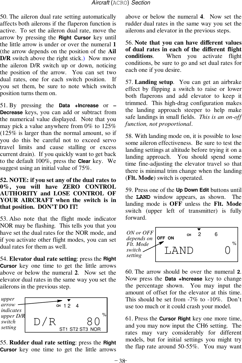

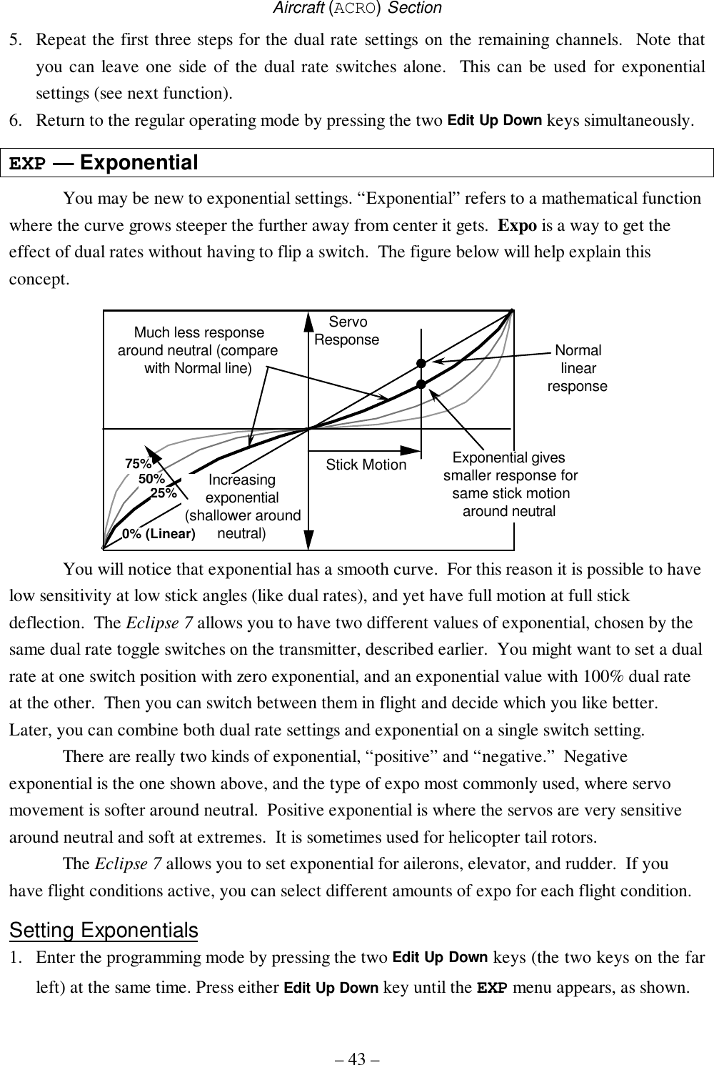
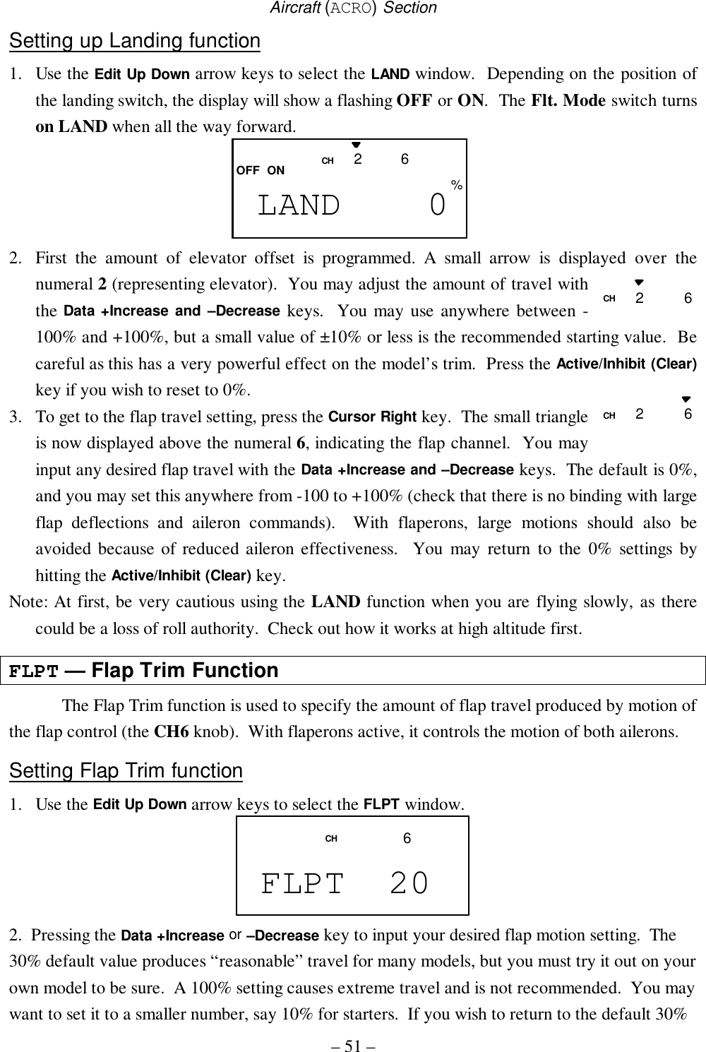


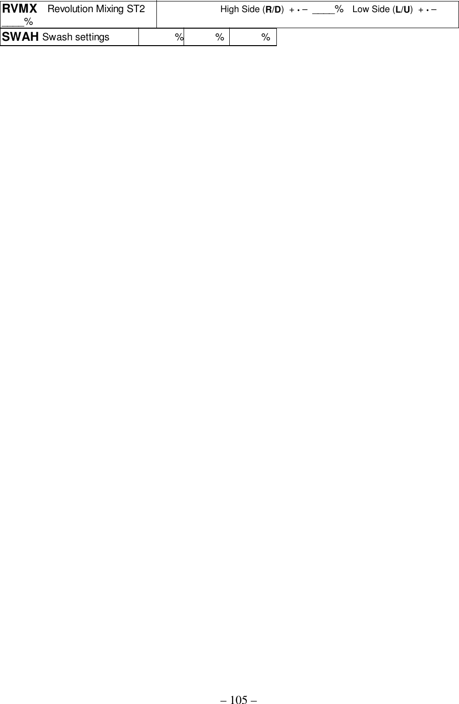
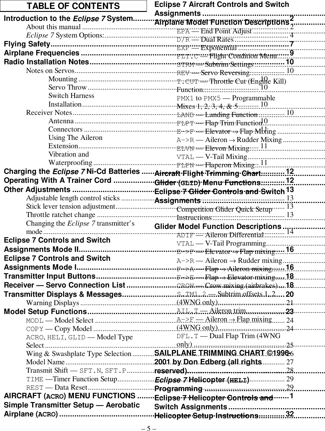
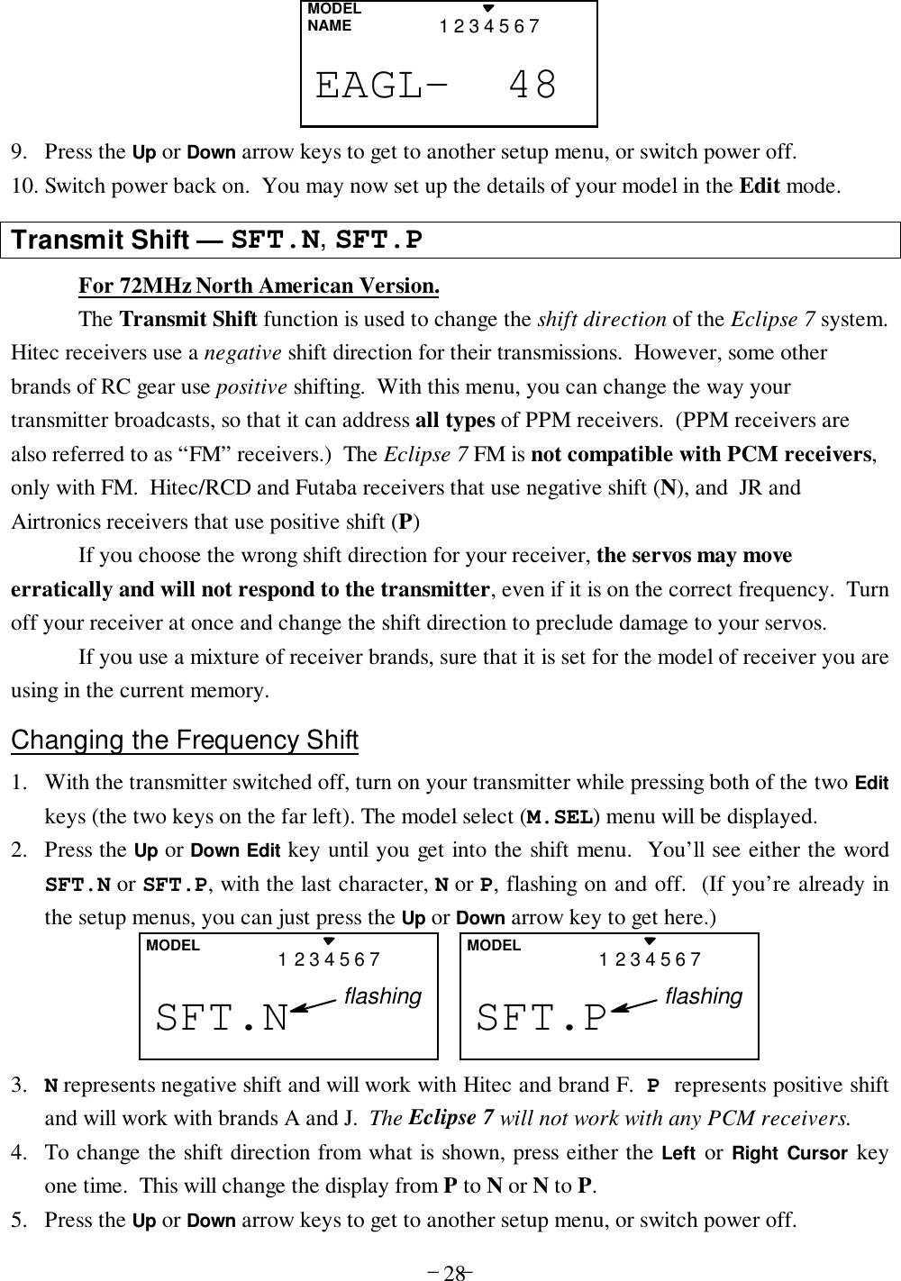
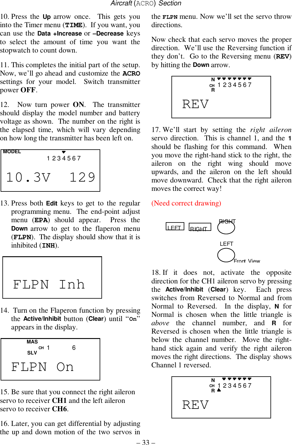
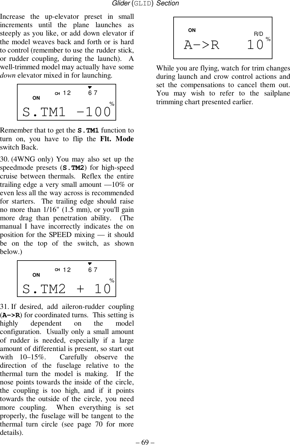
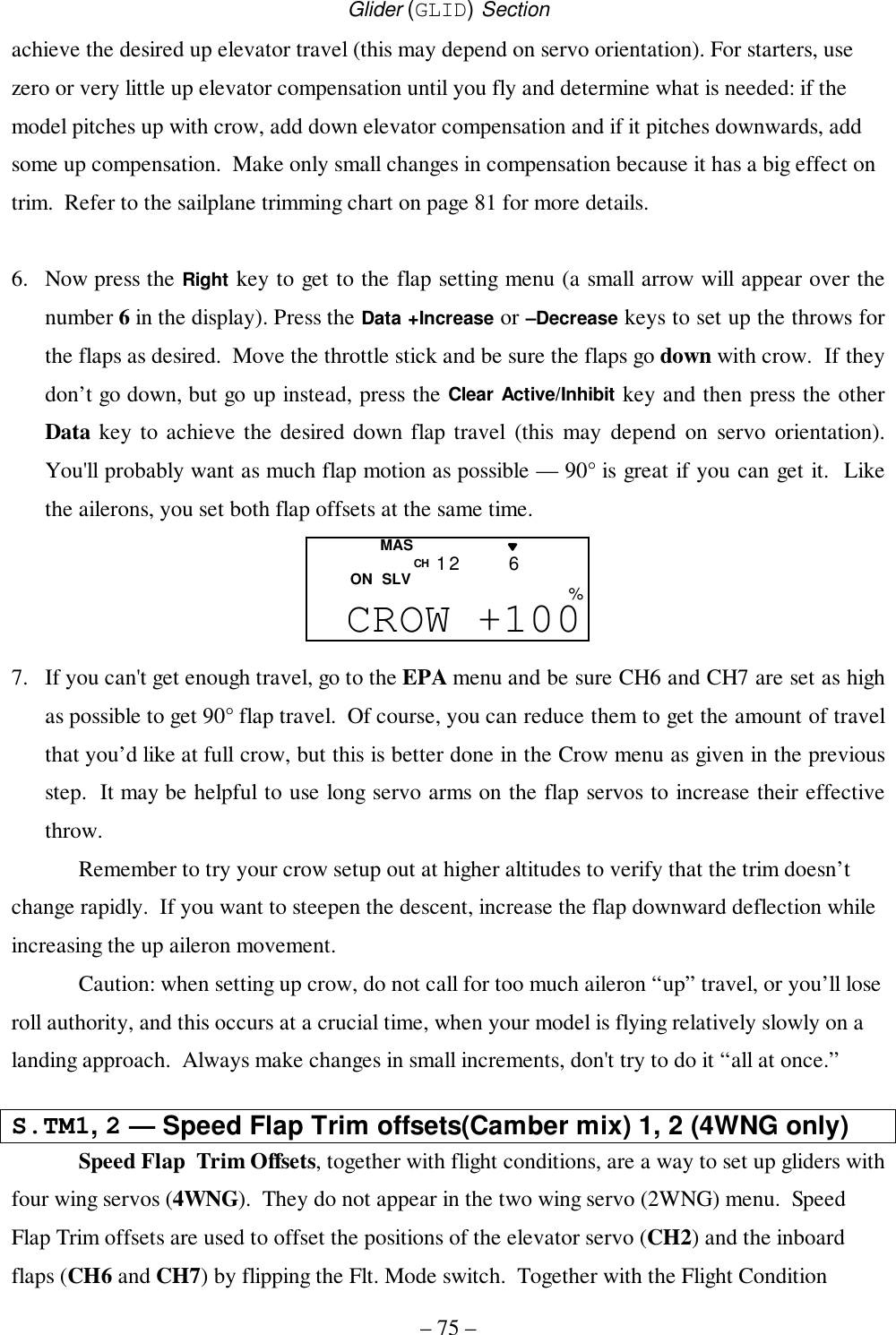
![Glider (GLID) Section– 63 –There are two different glider modes in the Eclipse 7system. You set them up in the Model Setup menus (seepage 26). 4WNG refers to a glider with four wing servos.2WNG refers to a model with two wing servos for flaperons,but this setup also applies to models with an additional flapor spoiler servo in CH6.Glider Functions Map ............................ (see right)Glider Setup Example........................................ 65EPA .............End point adjust ............................ 41D/R .............Dual Rates..................................... 42EXP .............Exponential................................... 43FLT.C.........Flight Condition ............................ 44STRM...........Subtrim.......................................... 47REV .............Servo Reverse ............................... 47PMX1-5.......Programmable Mixer #1– #5 ........ 49ADIF...........Aileron Differential....................... 55VTAL...........V-Tail............................................ 55E->F...........Elevator → Flap mixing................. 52A->R...........Rudder Coupling........................... 52F->A...........Flap → Aileron mixing................... 72F->E...........Flap → Elevator mixing................. 73CROW...........Crow mixing (airbrakes) ............... 73AIL.T.........Aileron Dual Trim......................... 77S.TM1, 2....Speed Flap trim offsets 1, 2 (GLID4) 75A->F...........Aileron → Flap mixing (GLID4) ... 77DFL.T.........Dual Flap Trim knob (GLID4)...... 78Glider Trimming Chart....................................... 81Useful Control & Switch InformationGear Switch controls receiver CH3VR1 controls camber (flap motions)VR2 controls receiver CH7 and sets DFL.TCH7 switch Forward = F->A On, F->E OnGEAR switch Back = CROW Off,Flt. Condition switch Back= A->F OffFlt. Mode switch Back (“speed”)= E->F On, S.TM1Flt. Mode switch Forward (“launch”) = S.TM2 OnDual Rate Set [D/R]End Point Adjust [EPA]Normal Display ModePress both Edit/Display keysProg. Mix 1 [PMX1] through Prog. Mix 5 [PMX5]Flight Cond. [FLT.C]Exponential [EXP]Sub-Trims [STRM]Servo Reversing [REV]Voltage/Timer Display Ail → Rud Mix [A-R]Crow Mix [CROW]Elev → Flap Mix [E-F]Ail Differential [ADIF]V-Tail [VTAL]Flap → Ail Mix [F-A]Flap → Ele Mix [F-E]Subtrim Set 1 [STM1]Subtrim Set 2 [STM2]Aileron Trim [AIL.T]Ail → Flap Mix [A-F]Dual Flap Trim [DFLT]44444=4WNG only](https://usermanual.wiki/Hitec-RCD/HPF-M72/User-Guide-140921-Page-63.png)

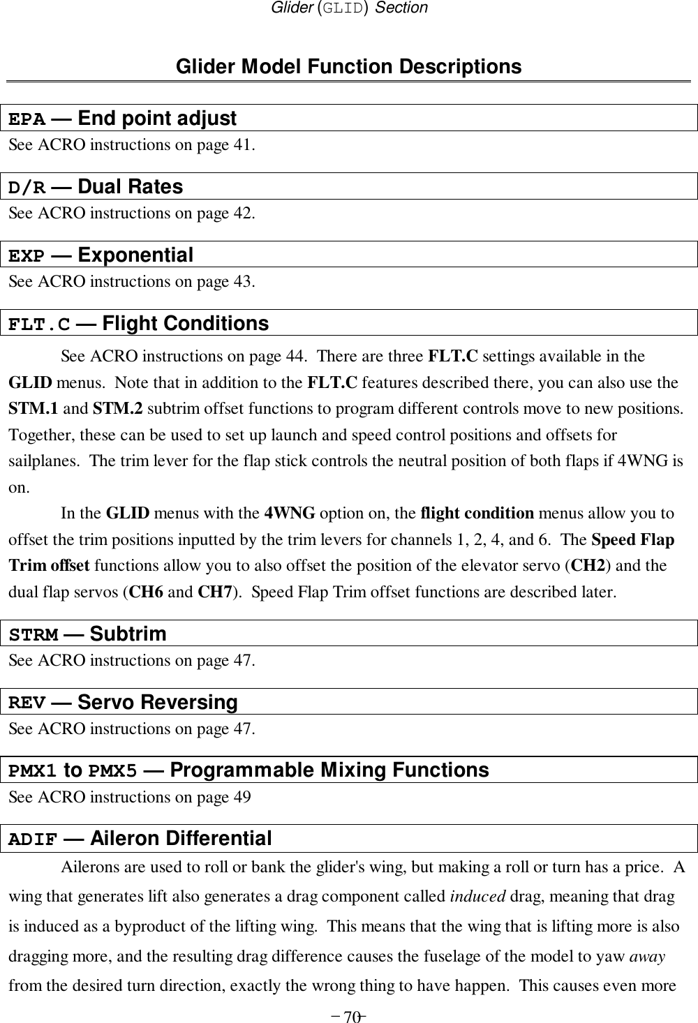
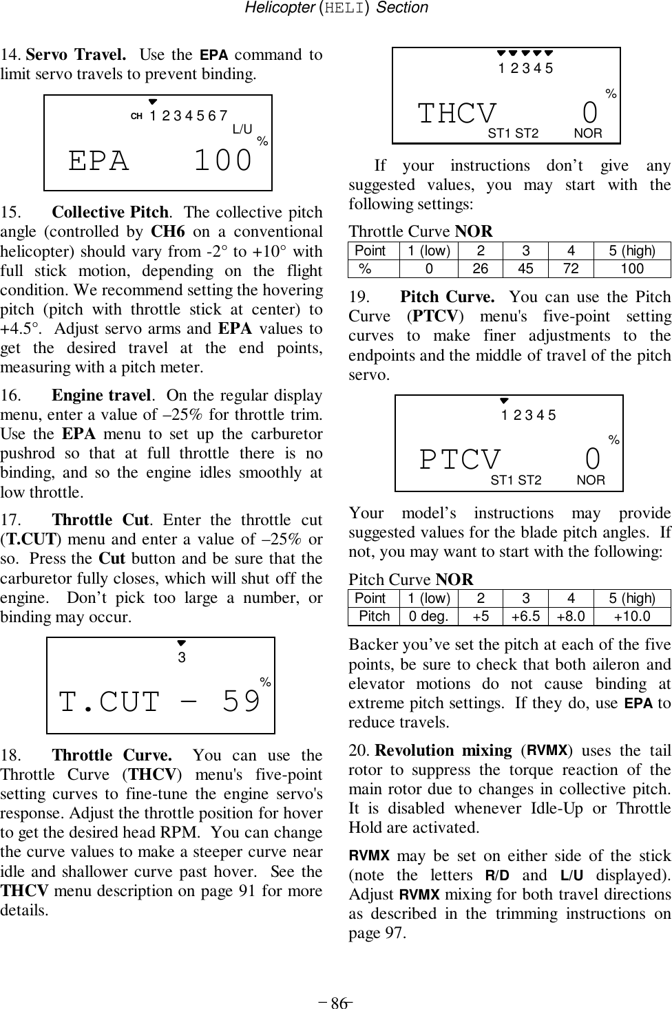
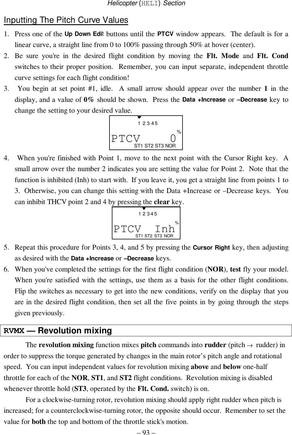
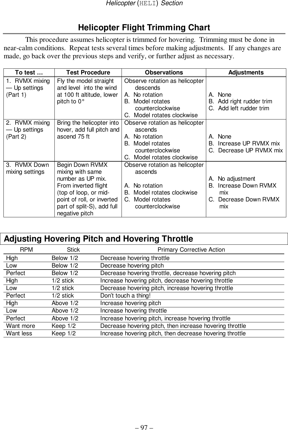
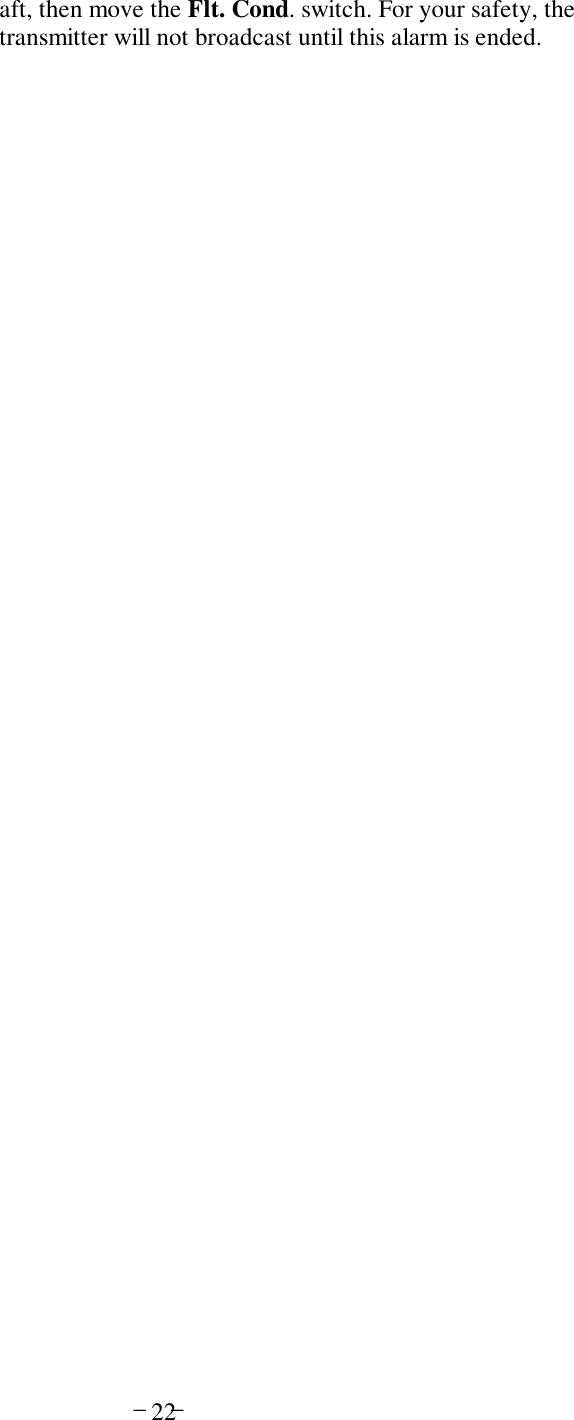
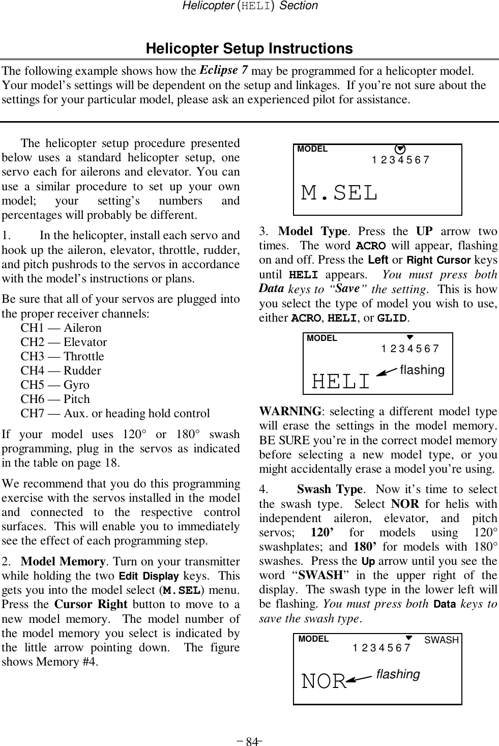
![Helicopter (HELI) Section– –82Eclipse 7 Helicopter (HELI) ProgrammingThis section describes how to use the Eclipse 7helicopter functions (model type HELI). Descriptions of theother functions, such as endpoints, dual rates, expo, etc., arecontained in the aircraft (ACRO) section.The HELI menu provides three flight conditions inaddition to the normal one (NOR). ST1 may be used forforward flight and mild aerobatics, ST2 may be used forinverted, and ST3 is used for autorotations.Helicopter Functions Map......................see rightHelicopter Setup Example...............................84R->T...........Rudder->Throttle mixing...............89GYRO...........Gyro Settings .................................90HOLD...........Throttle Hold .................................90THCV...........Throttle Curve ...............................91PTCV...........Pitch Curve....................................91RVMX...........Revolution mixing..........................92SWAH...........Swashplate settings (120’, 180’)....94Hovering Pitch Adjusting knob...........................96Hovering Throttle Adjusting knob......................96Helicopter Trimming Chart ............................97The Eclipse 7 system comes with three choices for thehelicopter’s swashplate arrangement, which may be found inthe setup menu: normal (NOR), 120° (120’), and 180°(180’). NOR is the standard swashplate where one servoeach performs the collective pitch, elevator, and aileronfunctions. 120° and 180° are intended for three-servoswashplates needing special mixing to get the servos toproperly provide the required pitch, elevator, and aileronfunctions.CH1CH2CH1CH6CH2NOR 180°CH2CH1CH6120°CH6Dual Rate Set [D/R] End Point Adjust [EPA] Press both Edit/Display keys Revolution [RVMX] Prog. Mix 2 [PMX2] Pitch Curve [PTCV] Rud → Thr Mix [R-T] Prog. Mix 1 [PMX1] Gyro setting [GYRO] Exponential [EXP] Sub-Trims [STM] Servo Reversing [REV] Throttle Cut [T.CUT] Throttle Curve [THCV] Throttle Hold [HOLD] Swashplate [SWAH] 120’, 180’ only Normal Display Mode Voltage/Timer Display](https://usermanual.wiki/Hitec-RCD/HPF-M72/User-Guide-140921-Page-82.png)
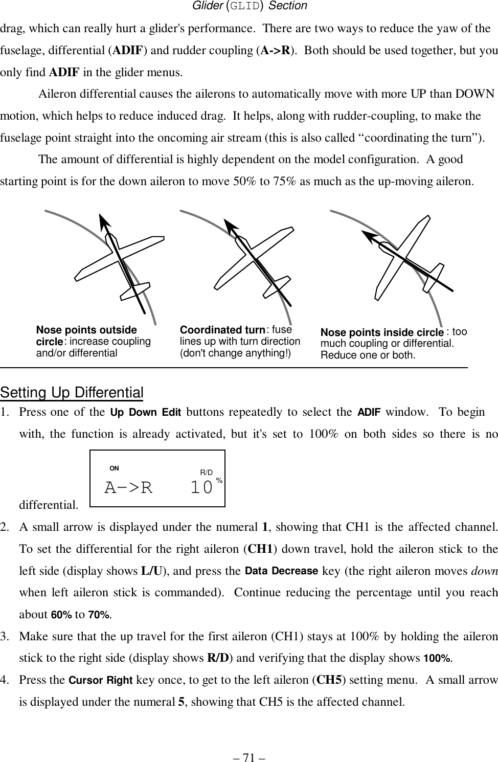
![Helicopter (HELI) Section– 85 –5. Name your model. Press the UP arrowonce. This gets you into the model namemode (note the words MODEL and NAME inthe upper left of the display).****- 0421 3 567MODEL6. Now you can select four letters to identifyyour model. With the first of the four lettersflashing, press the Data +Increase or –Decrease keys to change the letter that isdisplayed. Stop when the first letter is the oneyou want.7. Press the Right Cursor key once to get tothe second letter. Repeat Step 5 to choose thesecond letter.8. Repeat the previous steps two more timesto fill out the remaining two letters. If youlike, you can hit the right cursor button onemore time and select a number between 0 and199 for further identification.9. Set the stopwatch. Press the UP arrowonce. This gets you into the Timer menu(TIME). Use the Data Increase and Decreasekeys to select the amount of time you want thestopwatch to count down. This is handy tokeep track of engine running time so you don'trun out of gas.TIME 10421 3 567MODEL10. This completes the initial part of the setup.Now, we’ll go ahead and customize thesettings for your model. Switch transmitterpower OFF.11. Servo Directions. Switch transmitterpower back on and check the proper directionof throw for each servo. Use the reversingfunction [REV] to reverse channels asnecessary to get proper throw directions.REVCH 4213567NR12. If you’re using 120’ or 180’ swash types,please use the swashplate (SWAH) menu,page 94, to adjust these responses.SWAH + 70CH 162%LEFT RIGHTRight Aileron: swashplate tilted towards the chopper's right side.Left Aileron: swashplate tilted towards the left side.DOWNUPDown Elevator: swashplate tilted towards the chopper's front.Up Elevator: swashplate tilted towards the rear.HIGHLOWHIGH Position: high rotor pitch AND carburetor fully openedLOW Position: low rotor pitch, carburetor at idle (use trim tab to fully close)LEFT RIGHT LEFTRIGHT13. Servo Neutrals. First, be sure the hoveringpitch and hovering throttle knobs are centered.Set up all linkages so that all servos are asclose to mechanical neutral as possible. Then,use the Subtrim (STRM) window to make fineadjustments on the servo neutrals.STRM 5CH 421 3 567](https://usermanual.wiki/Hitec-RCD/HPF-M72/User-Guide-140921-Page-85.png)