Hitec RCD HPF-M72 R/C of Model Aircraft User Manual User Instructions
Hitec RCD Inc. R/C of Model Aircraft User Instructions
User Instructions
– 1 –
Hitec®
ECLIPSE 7
Owner’s Manual
SYSTEM INSTRUCTION MANUAL
FOR AIRCRAFT • GLIDERS •
HELICOPTERS
7 CHANNELS • 7 MEMORIES •
PROGRAMMABLE FM SHIFT

Introduction to the Eclipse 7
System
Congratulations! You now own a
Hitec® Eclipse 7, an extremely versatile R/C
system that may be effectively used by both
beginning and master pilots. The transmitter
may be programmed for airplanes, gliders, or
helicopters, all with special mixing functions,
so it can accommodate virtually any model
configuration. You can store programming for
seven different models in this powerful
system! The transmitter will remember all of
your settings for each of your different models
forever — no backup battery is ever needed.
With programmable shift, it can be used with
all PPM/FM receiver models, even other
brands!
The system pushbuttons allow rapid
data input into the easy-to-read LCD display.
With its electronic digital trims, you’ll never
lose your trim positions again, because they
stay at the same place you left them!
Standard programming features include
servo reversing for all channels, end point
adjust on all channels, dual rates, and
exponential. Pre-programmed functions and
programmable mixers allow you to use the
system for any type of model you can imagine.
For those learning to fly, the transmitter has
“buddy-box” capability (a second transmitter
may be connected for training by an instructor
pilot with an optional trainer cord). The
Eclipse 7 menus even have the advanced
“flight condition” settings found in other
radios costing hundreds of dollars more in all
its menus!!
The extensive preprogrammed mixing
features for aircraft include flaperon (dual
aileron servos), V-tail, elevon (for flying-wing
models), landing settings, throttle cut,
aileron →rudder mixing, and elevator → flap.
Five programmable mixers for custom
functions are also provided.
For sailplanes, you find the following
custom programming for competition and
sport models with two or four wing servos:
crow mixing for spot landings, flap → aileron
mixing, aileron → flap, elevator → flap,
aileron → rudder, flap → elevator, two sets of
switchable offsets for launching and speed, V-
tail, aileron differential, and five
programmable mixers. The second aileron is
on channel 5, so you can use the system with
ultralight five-channel receivers without any
problems!
Helicopter features include five-point
pitch and throttle curves, high and low
revolution mixing, throttle cut, throttle hold,
gyro settings, and rudder → throttle mixing.
You may select a conventional swashplate, or
if you have a more complex chopper, mixing is
provided for two types of three-servo
swashplates.
About this manual
This manual is not just a translation —
it has been carefully written from scratch to be
– 3 –
as helpful to you, the new owner, as possible.
There are many pages of setup procedures,
examples, explanations, and trimming
instructions. In order for you to make the best
use of your system and to fly safely, please
read this manual carefully. If you don’t have
time to read it thoroughly, at least spend some
time browsing through it to see all the features
this fine system has to offer.

Eclipse 7 System Options:
1. Airplane Version, Item #171721.
Includes four HS-422 deluxe servos, 8
channel Supreme receiver, 600 mAH
airborne battery, standard switch harness,
12" (30 cm) servo extension cord, and
overnight wall charger.
2. Airplane Spectra Version, Item
#171723. Includes four HS-425BB ball-
bearing servos, Spectra programmable
frequency module, 8 channel Super Slim
receiver, 600 mAH receiver battery,
heavy-duty switch, 12" (30 cm) servo
extension cord, overnight wall charger.
3. Helicopter Version, Item #171725.
Includes five HS-425BB ball-bearing
servos, 8-channel Supreme receiver, 1000
mAH receiver battery, heavy-duty switch
harness, and overnight wall charger.
These versions come with the
following accessories:
• Frequency number flag
• Hardware and mounting package for
all the servos
• Additional “smooth click” throttle
ratchet
• "Flight preserver" closed-cell foam
wrap to protect the receiver from
shock and vibration.
• Warranty card
• Manual
4. Eclipse Transmitter only, with Spectra
module, Item #171724. Eclipse
transmitter with Spectra Synthesizer
Module, manual, overnight wall charger,
and warranty card.
This product is to be used for sport and
recreational flying of radio-control models
only. Hitec is not responsible for the results of
use of this product by the customer or for any
alteration of this product, including
modification or incorporation into other
devices by third parties. Modification will
void any warranty and is done at owner’s risk.
If you have any difficulties, please
consult this manual, your hobby dealer, or
Hitec (contact information is provided in the
rear of this manual). Note the information
contained in this manual is subject to change
without notice due to possible changes in
manufacturing procedures, system software
programming, or updates.
“Hitec” is a registered trademark of the Hitec
RCD, Inc.
Disclaimer: This information specific to
North American versions of the Eclipse.

– 5 –
TABLE OF CONTENTS
Introduction to the Eclipse 7 System........................................................................2
About this manual ...............................................................................................................2
Eclipse 7 System Options:................................................................................................... 4
Flying Safety..............................................................................................................7
Airplane Frequencies ................................................................................................9
Radio Installation Notes..........................................................................................10
Notes on Servos.................................................................................................................10
Mounting................................................................................................. 10
Servo Throw............................................................................................ 10
Switch Harness
Installation............................................................................................... 10
Receiver Notes.................................................................................................................. 10
Antenna ................................................................................................... 10
Connectors .............................................................................................. 11
Using The Aileron
Extension................................................................................................. 11
Vibration and
Waterproofing......................................................................................... 11
Charging the Eclipse 7 Ni-Cd Batteries ..................................................................12
Operating With A Trainer Cord ...............................................................................12
Other Adjustments ..................................................................................................13
Adjustable length control sticks ........................................................................................ 13
Stick lever tension adjustment........................................................................................... 13
Throttle ratchet change ..................................................................................................... 13
Changing the Eclipse 7 transmitter’s
mode.................................................................................................................................. 14
Eclipse 7 Controls and Switch
Assignments Mode II...............................................................................................16
Eclipse 7 Controls and Switch
Assignments Mode I................................................................................................16
Transmitter Input Buttons.......................................................................................18
Receiver — Servo Connection List .........................................................................18
Transmitter Displays & Messages...........................................................................20
Warning Displays .............................................................................................................. 21
Model Setup Functions...........................................................................................23
MODL — Model Select ...................................................................................................... 24
COPY — Copy Model ....................................................................................................... 24
ACRO, HELI, GLID — Model Type
Select ................................................................................................................................. 25
Wing & Swashplate Type Selection.................................................................................. 26
Model Name......................................................................................................................27
Transmit Shift — SFT.N, SFT.P..................................................................................... 28
TIME —Timer Function Setup.......................................................................................... 29
REST — Data Reset.......................................................................................................... 29
AIRCRAFT (ACRO) MENU FUNCTIONS ......................................................................1
Simple Transmitter Setup — Aerobatic
Airplane (ACRO)........................................................................................................32
Eclipse 7 Aircraft Controls and Switch
Assignments ........................................................
.
Airplane Model Function Descriptions ...............
.
EPA — End Point Adjust ......................................
.
D/R — Dual Rates................................................
.
EXP — Exponential ..............................................
.
FLT.C — Flight Condition Menu.........................
.
STRM — Subtrim Settings .....................................
.
REV — Servo Reversing........................................
.
T.CUT — Throttle Cut (Engine Kill)
Function.................................................................
.
PMX1 to PMX5 — Programmable
Mixes 1, 2, 3, 4, & 5..............................................
.
LAND — Landing Function...................................
.
FLPT — Flap Trim Function.................................
.
E->F — Elevator → Flap Mixing .........................
.
A->R — Aileron → Rudder Mixing......................
.
ELVN — Elevon Mixing........................................
.
VTAL — V-Tail Mixing.........................................
.
FLPN — Flaperon Mixing.....................................
.
Aircraft Flight Trimming Chart.............................
.
Glider (GLID) Menu Functions.............................
.
Eclipse 7 Glider Controls and Switch
Assignments ........................................................
.
Competition Glider Quick Setup
Instructions............................................................
.
Glider Model Function Descriptions ...................
.
ADIF — Aileron Differential................................
.
VTAL — V-Tail Programming...............................
.
E->F — Elevator → Flap mixing..........................
.
A->R — Aileron → Rudder mixing......................
.
F->A — Flap → Aileron mixing............................
.
F->E — Flap → Elevator mixing..........................
.
CROW — Crow mixing (airbrakes) ........................
.
S.TM1, 2 — Subtrim offsets 1, 2
(4WNG only).........................................................
.
AIL.T — Aileron trim..........................................
.
A->F — Aileron → Flap mixing
(4WNG only).........................................................
.
DFL.T — Dual Flap Trim (4WNG
only) ......................................................................
.
SAILPLANE TRIMMING CHART ©1996-
2001 by Don Edberg (all rights
reserved)...............................................................
.
Eclipse 7 Helicopter (HELI)
Programming .......................................................
.
Eclipse 7 Helicopter Controls and
Switch Assignments............................................
.
Helicopter Setup Instructions..............................
.
Menu Descriptions — Helicopter ............................................................................88
Flight Conditions................................................................................................................88
R->T — Rudder → Throttle Mixing..................................................................................89
GYRO — Gyro settings.......................................................................................................90
HOLD — Throttle Hold......................................................................................................90
THCV — Throttle Curve ....................................................................................................91
PTCV — Pitch Curve.........................................................................................................92
RVMX — Revolution mixing..............................................................................................93
SWAH — Swashplate adjust (120’, 180’
only)...................................................................................................................................94
Hovering Throttle Adjustment Knob.................................................................................96
Hovering Pitch Adjustment Knob......................................................................................96
Helicopter Flight Trimming Chart............................................................................97
Adjusting Hovering Pitch and
Hovering Throttle ..............................................................................................................97
GLOSSARY ..............................................................................................................98
ACRO Model Data Recording Sheet........................................................................100
GLID Model Data Recording Sheet........................................................................102
HELI Model Data Recording Sheet........................................................................104

– 7 –
Flying Safety
To ensure your own safety and the safety of
others, please observe the following
precautions:
Charge the Batteries!
Be sure to recharge the batteries before
each flying session. A battery low in charge
will soon die, causing loss of control and a
crash. Plug in the charger that comes in this
system and hook up the transmitter and
airborne batteries the day before a planned
flying session. When you begin your flying
session, reset the transmitter's timer to keep
track of how long the system’s been used, and
monitor the transmitter’s voltage display. Quit
flying long before your batteries become low.
Beware of on-field charging of your
batteries with a field charger. A fast-charger
may overcharge the Ni-Cd batteries, causing
overheating and a premature failure. Never
charge your transmitter or receiver battery at a
rate higher than 2 amps.
Flying field
We recommend that you fly at a
recognized model airplane flying field. You
can find model clubs and fields by asking your
nearest hobby dealer, or contacting the
Academy of Model Aeronautics. Always pay
particular attention to the flying field’s rules,
as well as the presence and location of
spectators, the wind direction, and any
obstacles on the field. Be very careful flying
in areas near power lines, tall buildings, or
communication facilities as there may be radio
interference in their vicinity. If you must fly
at a site that is not a club field, be sure there
are no other modelers flying within a two-
mile range, or you may lose control of your
aircraft.
Once you arrive at the flying field…
Before flying, be sure that the frequency
you intend to fly with is not in use, and secure
any frequency control device (pin, tag, etc.)
for that frequency before turning on your
transmitter. Never believe that it’s possible to
fly two or more models on the same frequency
at the same time. Even though there are
different types of modulation (AM, PPM or
FM, and PCM), only one model may be flown
on a single frequency.
When you are ready to fly your model,
position the throttle stick to its low speed
position, or do whatever is necessary to
command your motor NOT to run. Then, you
may turn on the transmitter power followed by
the receiver power. When you have finished
flying, begin by turning off the receiver power,
then turn off the transmitter power. If you do
not follow these procedures, you may damage
your servos or control surfaces, flood your
motor, or in the case of electric-powered
models, the motor may unexpectedly turn on
and cause a severe injury.
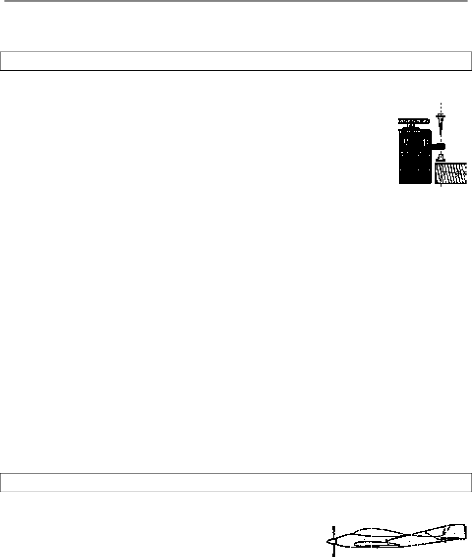
Before starting the engine, fully retract the
transmitter antenna, power up the transmitter
and receiver, and check to be sure that the
servos follow the movement of the sticks. If a
servo operates abnormally, don’t attempt to
fly until you determine the cause of the
problem. We recommend that you range-
check your system before each flying session.
Have an observer verify that the system works
with the transmitter about 30 paces away with
the transmitter antenna collapsed. Finally,
before starting the engine, be sure to check
that the transmitter model memory is correct
for the chosen model.
While you’re getting ready to fly, if you
place your transmitter on the ground, be sure
that the wind won’t tip it over. If it is knocked
over, the throttle stick may accidentally get
moved causing the engine to race
unexpectedly.
Before taxiing, be sure to extend the
transmitter antenna to its full length. A
collapsed antenna will reduce your flying
range and may cause a loss of control. It is a
good idea to avoid pointing the transmitter
antenna directly at the model at all times,
since the signal is weakest in that direction.
Finally, don’t fly in the rain! Water or
moisture may enter the transmitter through the
antenna or stick openings and cause erratic
operation or loss of control. If you must fly in
wet weather during a contest, be sure to
protect your transmitter with a plastic bag or
waterproof barrier.
– 9 –
Airplane Frequencies
The following frequencies and channel
numbers may be used for flying aircraft in the
U.S. (this information specific to North
American versions of the Eclipse):
72
MHz
bandC
h . No.
MHz
11 72.010 36 72.510
12 72.030 37 72.530
13 72.050 38 72.550
14 72.070 39 72.570
15 72.090 40 72.590
16 72.110 41 72.610
17 72.130 42 72.630
18 72.150 43 72.650
19 72.170 44 72.670
20 72.190 45 72.690
21 72.210 46 72.710
22 72.230 47 72.730
23 72.250 48 72.750
24 72.270 49 72.770
25 72.290 50 72.790
26 72.310 51 72.810
27 72.330 52 72.830
28 72.350 53 72.850
29 72.370 54 72.870
30 72.390 55 72.890
31 72.410 56 72.910
32 72.430 57 72.930
33 72.450 58 72.950
34 72.470 59 72.970
35 72.490 60 72.990
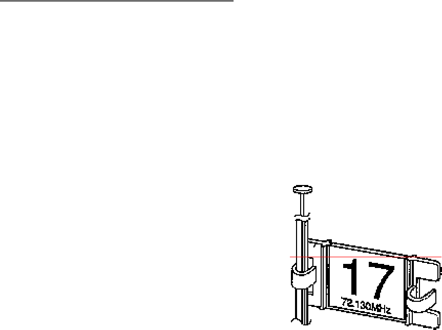
Installing your frequency number indicator
It is very important to display your transmitters channel number at all times. To install your
frequency flag device on your transmitters antenna, slide the appropriate paper numbers into the
slots and slip the device onto the transmitters antenna.
– –
10
Radio Installation Notes
While you are installing the battery, receiver, and servos into your model’s fuselage,
please pay attention to the following guidelines:
Notes on Servos
Mounting
When you mount each servo, use the supplied rubber grommets and
insert an eyelet up through the bottom. Be sure not to overtighten the screws. If
any portion of the servo case directly contacts the fuselage or the servo rails, the
rubber grommets will not be able to attenuate vibration, which can lead to
mechanical wear and servo failure.
Servo Throw
Once you have installed the servos, operate each one over its full travel and check that
the pushrod and output arms do not bind or collide with each other, even at extreme trim settings.
Check to see that each control linkage does not require undue force to move (if you hear a servo
buzzing when there is no transmitter control motion, most likely there is too much friction in the
control or pushrod). Even though the servo will tolerate loads like this, they will drain the battery
pack much more rapidly.
Switch Harness Installation
When you are ready to install the switch harness, remove the switch cover and use it as a
template to cut screw holes and a rectangular hole slightly larger than the full stroke of the
switch. Choose a switch location on the opposite side of the fuselage from the engine exhaust,
and choose a location where it can’t be inadvertently turned on or off during handling or storage.
Install the switch so that it moves without restriction and “snaps” from ON to OFF and vice
versa.
Receiver Notes
Antenna
DO NOT cut or coil the receiver antenna wire. It is
normal for the receiver antenna to be longer than the fuselage.
DO NOT cut it or fold it back on itself – cutting or folding changes the electrical length of the
antenna and may reduce range. Secure the antenna to the top of the vertical fin or the tailboom,
and let the excess length trail behind the aircraft (be sure it cannot tangle with the tail rotor on a
helicopter).
– 11 –
You may run the antenna inside of a non-metallic housing within the fuselage (a plastic
outer pushrod housing works well for this), but range may suffer if the antenna is located near
metal pushrods or cables. Be sure to perform a range check before flying. With the antenna
collapsed, you should be able to walk 20 - 30 paces from the model without losing control or
seeing “jitter” in the servos. The range check should be done with the motor running and the
model should be securely restrained in case of loss of control.
Connectors
Be sure the alignment of a servo or battery connector is correct before inserting it into the
receiver. To remove a connector from the receiver, try to pull on the connector’s plastic housing
rather than pulling on the wires. Pulling the wires can ruin the connector pins and break wires.
Using The Aileron Extension
If any of your servos are located too far away to plug directly into the receiver (like the
aileron servo), or you need to unplug the servo each time you disassemble the model, use a servo
extension cord to extend the length of the servo lead. Additional Hitec extension cords of
varying lengths are available from your hobby dealer.
Vibration and Waterproofing
The receiver contains precision electronic parts. Be sure to avoid vibration, shock, and
temperature extremes. For protection, wrap the receiver in the provided “Flight Preserver” foam
rubber, or use some other vibration-absorbing materials. It’s also a good idea to waterproof the
receiver by placing it in a plastic bag and securing the open end of the bag with a rubber band
before wrapping it with foam. If you accidentally get moisture inside the receiver, you may
experience intermittent operation or a crash.

– –
12
Charging the Eclipse 7 Ni-Cd Batteries
1. Connect the transmitter charging cord into the charging socket (on the rear of the case, left
side) and airborne Ni-Cd batteries to the receiver connector on the charger.
2. Connect the receiver battery to the charging cord.
3. Plug the charger into a wall socket.
4. The charger’s LEDs should light, indicating charging current is flowing. The batteries should
be left on charge for about 15 hours.
• Try to charge the batteries with the charger supplied with your system exclusively. The use of a
fast-charger may damage the batteries by overheating and dramatically reduce their lifetime.
NOTE: If you need to remove or replace the transmitter battery, do not pull on its wires to
remove it. Instead, gently pull on the connector’s plastic housing where it plugs in to the
transmitter. The battery must be removed to charge it properly with a "peak" charger.
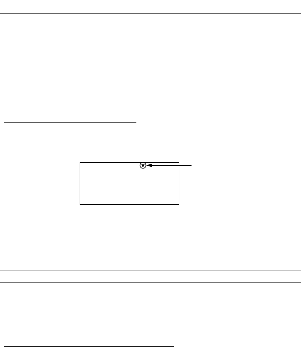
Operating With A Trainer Cord
An optional training cord is available from your dealer. The cord may be used to help a
beginning pilot learn to fly easily by allowing a second transmitter, operated by an experienced
instructor, to be connected to this system. The instructor may override the beginning pilot at any
time to bring the model back under safe control. For training, the transmitter may be connected
to another Hitec FM system, as well as to any Futaba® FM transmitter (if Hitec cord #58310 is
used).
To use the trainer cord:
1. Set up both the student’s and instructor’s transmitters to have identical trim and control
motions. If the instructor’s transmitter is on a different frequency than the student’s, use the
student’s as the master transmitter and the other as the student’s.
2. Collapse the student's antenna, and fully extend the instructor's antenna. If the student's
transmitter has a removable RF module, remove it from the transmitter.
– 13 –
3. The Hitec cord is specifically marked at one end as the
“master” the other end as “student”. Plug it accordingly into
each transmitter, with power switched off. The trainer jack is
on the back of the transmitter. Turn the connector until its
notches line up and it fits without having to be forced.
4. Turn on the instructor’s transmitter. DO NOT turn on the
student transmitter power. Move the controls on the
instructor’s transmitter, and verify each control moves the
proper direction. Now verify that the student’s trims and
control travels match the instructor’s by using the trainer
switch (the momentary Trainer switch on the top left of the
transmitter case) and switching back and forth while leaving
the control sticks and trims alone, then moving the control
sticks.
5. The instructor’s transmitter has normal control over the model unless the trainer switch is
pulled, passing control to the student’s transmitter. If the student loses control, the instructor
can quickly "take over" by releasing the trainer switch and controlling the model.
Other Adjustments
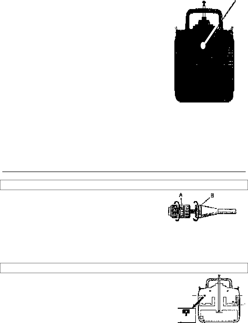
Adjustable length control sticks
You may change the length of the control sticks to
make your transmitter more comfortable to hold and
operate. To lengthen or shorten your transmitter’s sticks,
first unlock the stick tip by holding locking piece B and
turning stick tip A counterclockwise. Next, move the
locking piece B up or down (to lengthen or shorten). When the length feels comfortable, lock the
position by turning locking piece B counterclockwise.
Stick lever tension adjustment
You may adjust the stick tension of your sticks to provide
the “feel” that you like for flying. To adjust your springs, you’ll
have to remove the rear case of the transmitter. Using a
screwdriver, remove the six screws that hold the transmitter’s rear
cover into position, and put them in a safe place. Place some
padding under the front of the transmitter and place it face-down on
the pad. Gently ease off the transmitter’s rear cover and move it to
include correct figure.
include correct figure.
include correct figure
identifying proper places

– –
14
the right side of the transmitter, carefully turning it as you would turn the page of a book. Now
you’ll see the view shown.
Using a small cross-point screwdriver, rotate the adjusting screw for each stick for the
desired spring tension. The tension increases when the adjusting screw is turned clockwise, and
decreases for counterclockwise motion. When you are satisfied with the spring tensions, you
may close the transmitter. Very carefully reinstall the rear cover. When the cover is properly in
place, tighten the six screws.
Ratchet change
Some pilots prefer a “softer” or “smoother” ratchet action on the throttle stick. Included
as an accessory in your Eclipse 7 system is an alternate ratchet that provides a smoother
ratcheting action.
After removing the back of the transmitter case as directed above in the “stick lever
tension adjustment” section, remove the ratchet retaining screw, remove the old ratchet and
replace with the new one.
Changing the Eclipse 7 transmitter’s mode
If you wish to change the mode of the transmitter, say from Mode 2 to Mode 1, return the
radio to Hitec for conversion. If you don’t know what this means, you don’t need to worry about
it!
Factory Service Repair Information
Please read the warranty card supplied with your system, and return it so your system will
be under warranty.
Before you decide to have your system repaired, if there is no apparent physical damage,
read this instruction manual again and check to be sure that you are operating the system as it is
supposed to be operated. If you are still having trouble, pack up your system in its original
shipping materials and send it to the factory or the nearest authorized Hitec R/C Service Center.
Be sure to include a note in your package that describes the trouble in as much detail as
possible, including:
• Symptoms of the problem in as much detail as you can provide, including any
unusual mounting conditions or equipment orientation
• A list of items you are sending, and what you want to be repaired.
• Your name, address, and telephone number.
– 15 –
If you have any questions regarding this product, please consult with Hitec’s service
center. The address and telephone numbers of our service center is given below. Telephone
inquiries are accepted from 8:00 AM to 4:30 PM weekdays (closed on holidays).
Hitec-RCD, Inc.
12115 Paine St.
Poway, CA 92064
Telephone: 1-858-748-6948
FAX 1--858-748-1767
Web site: http://www.hitecrcd.com

– –
16
Eclipse 7 “Mode 2” Controls and Switch Assignments
Insert “Eclipse 7 Mode 2 Switch Configuration List” drawing
here (PDF file).
This figure shows the assignments for a Mode 2 system as supplied by the factory in North
America. Note that some of the functions will not operate until activated in the mixing menus.

– 17 –
Eclipse 7 “Mode 1” Controls and Switch Assignments
Insert “Eclipse 7 Mode 1 Switch Configuration List” drawing
here (PDF file).
This figure shows the assignments for a Mode 1 system as supplied by the factory (not in North
American versions). Note that some of the functions will not operate until activated in the
mixing menus.
– –
18
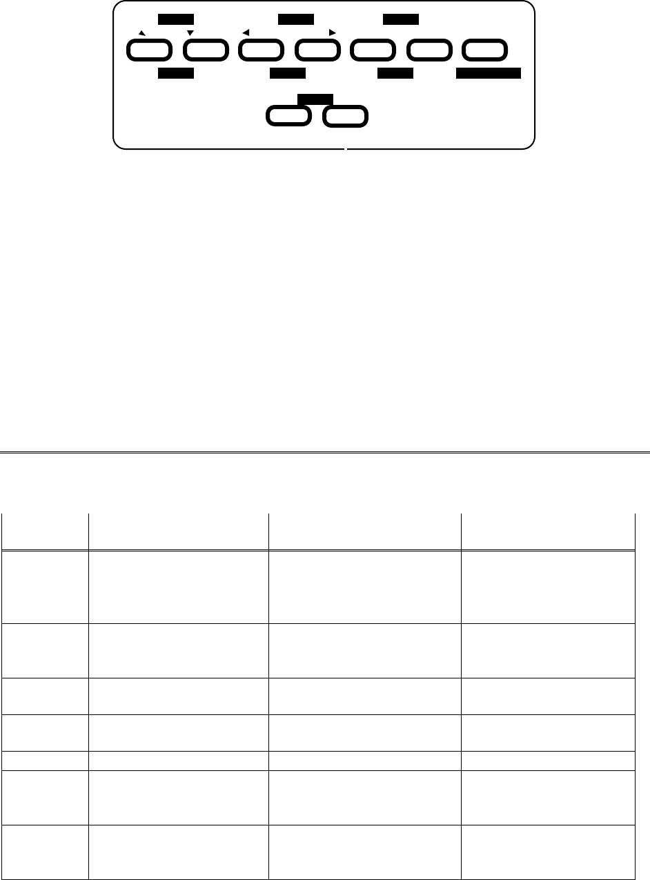
Transmitter Input Buttons:
Engine
Left Right Increase Decrease ClearDown Up
Lock Cut
DataCursor
Timer Save Active/InhibitDisplay
Edit
1 122334
56
The buttons are used for different things as follows:
1. The Edit/Display Up & Down buttons allow you to move up and down within the model menus,
and move within the regular display.
2. The Cursor Left/Right buttons allow you to select options within a particular function, and
control the timer function.
3. The Data +Increase & –Decrease buttons allow you to increase or decrease the numerical
settings for a function.
4. The Clear Active/Inhibit button resets numbers and turns functions on and off.
5. The Engine Lock button holds the throttle channel while other channels may respond to the
transmitter.
6. The Engine Cut button closes the throttle so that you can kill the engine without touching the
trim lever
You’ll learn how to use these buttons in the setup sections that follow.
Receiver — Servo Connection List
The table below shows the hookups that should be used for each of the model types.
Note that some functions shown will not operate until they are activated in the transmitter.
Receiver
channel Aircraft
(ACRO) Glider
(GLID) Helicopter
(HELI)
1aileron
or right aileron
or right flaperon (FLPN)
or right elevon (ELVN)
right aileron
(or rudder for rudder-
elevator models)
aileron
or swash servo 1 (120’)
or swash servo 1 (180’)
2Elevator
or V-tail right side (VTAL)
or left elevon (ELVN)
elevator or
V-tail right side (VTAL)elevator
or swash servo 2 (180’)
3throttle spoiler, throttle (on-off
controlled by Gear switch) throttle
4rudder or
V-tail left side (VTAL)rudder or
V-tail left side (VTAL)rudder
5landing gear left aileron gyro sensitivity
6flap (controlled by VR1)
or left flaperon (FLPN)
or left aileron
right flap (4WNG)
or single flap (2WNG)pitch
or swash servo 2 (120’)
or swash servo 3 (180’)
7optional, controlled by
VR2 left flap (4WNG)
or proportional channel,
controlled by VR2 (2WNG)
optional, controlled by
Gear switch
– 19 –
The servo response varies with the selected function. Standard options are shown first.
– –
20
Transmitter Displays & Messages
When you first turn on your transmitter, the first screen shown below appears on the LCD
display. Before flying, or even starting the engine, BE SURE that the model number
appearing in the lower right of the display matches the model that you are about to fly! If
you don’t, reversed servos and incorrect trims will lead to an immediate crash.
You can scroll up and down through the startup screen by pressing one of the two Edit keys
(the two keys on the far left). If you press timer or engine cut or lock keys, you go directly to
those functions regardless of the display.
Timer Display
Normal Display Mode
Voltage/Timer Display
Trim Menu [TRIM]
Model Name Display
Start/Stop key
Off key
Engine Cut
Cut key
Throttle Lock
Lock key
10.3V 129
4213567
MODEL This screen appears at startup. The model memory number is
shown by the small down-arrow. Battery voltage is shown in
the bottom left, and operating time is on the lower right. You
can reset the operating time display by hitting the Clear button
(the one on the farthest right). Do this after each charge to keep
track of your operating time on a single charge.
TRIM 0
CH
%
ST1
4216
ST2 ST3 NOR
Pressing the Up button gives the Trim display (different
numbers may appear depending on the model type). To see
where the trim for a certain channel is, you have to move it! Be
sure to move it back to where it was. Note that the CH3 trim
only moves downward, so if you need more engine RPM, set up
idle with the trim at –25% so you can increase it if needed.
EAGL- 1
4213567
MODEL
Pressing the Up button again gives the Model Name display. If
you’ve named your model, it will appear here so you can be
sure you have recalled the correct memory. If you do not name
the model, you'll have to remember which model memory it's
– 21 –
stored within by the memory number.
9:56 136
4213567
MODEL
Pressing the start/stop button gives the Timer display, with a
stopwatch display on the left, and operating time on the right.
This also starts the timer, so hit the start/stop key again to stop
it. Hitting the Cursor Left (Off) button resets the timer and
return to display mode.
10.1V 10
421 3 567
MODEL LOCK
LOCK indicator
Pressing the Lock button locks the throttle servo and holds it
where you last commanded it. This may be used as a safety
feature when you are carrying the model and transmitter to
ensure you don’t accidentally give throttle. It is shown by the
LOCK indicator.
Warning Displays
L.BATT 155
4213567
MODEL The LOW BATTERY warning is displayed when the
transmitter battery voltage drops below 9.3 volts, and a beeper
sounds. The operating time is still shown on the right. If you
reset this each time you charge the system, you will have a good
idea of how long you can safely operate.
WHEN THE BEEPER SOUNDS, LAND YOUR MODEL
AS SOON AS POSSIBLE BEFORE LOSS OF CONTROL
DUE TO A DEAD RECEIVER BATTERY.
IDLE On
The IDLE ON warning is displayed when the transmitter is
powered up with the Idle switch on in the helicopter mode only.
You can turn this off by moving the Flt. Mode switch or the
Flt. Cond. switch forward. If you switch the Flt. Cond. switch
and you get the HOLD ON alarm (see below), you must move
the Flt. Mode switch fully aft, then move the Flt. Cond. switch.
For your safety, the transmitter will not broadcast until this
alarm is ended.
HOLD On
The HOLD ON warning is displayed when the transmitter is
powered up with the Throttle hold switch on in the helicopter
mode only. You can turn this off by moving the Flt. Cond.
switch forward (this switch is on the top right, in the rear). If
you switch the Flt. Cond. switch and you get the IDLE ON
alarm (see below), you must move the Flt. Mode switch fully
– –
22
aft, then move the Flt. Cond. switch. For your safety, the
transmitter will not broadcast until this alarm is ended.
Aircraft (ACRO) Section
– 23 –
Model Setup Functions
This section describes the model setup functions that are used to choose all of the
operating features of a particular model memory. These functions are used to select the
model memory, the model type (from airplanes, gliders, and helicopters), set the
stopwatch, and other useful functions. These functions are used to set up a new model or
a new model memory, to switch between memories, and to change transmit shift..
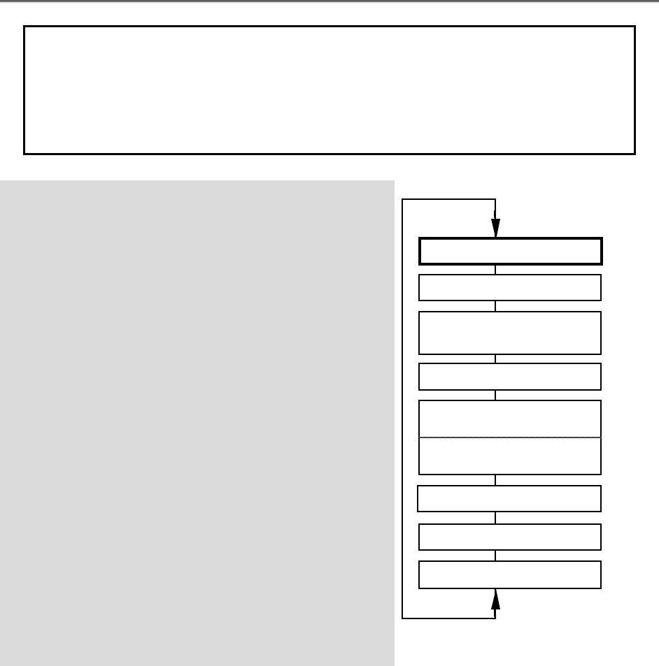
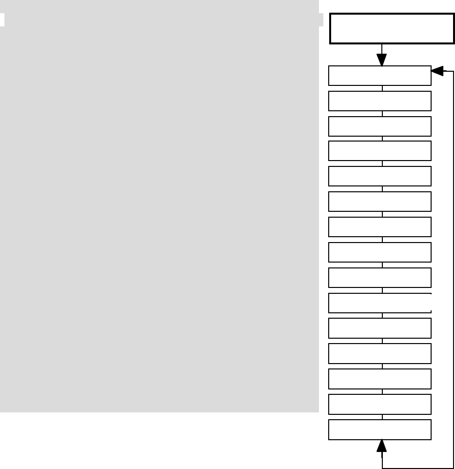
Map of Basic Menu Functions...............(see right)
M.SEL..... Model select .......................................24
COPY ....... Data Copy ..........................................24
ACRO ....... Acrobatic model mode .......................25
HELI ....... Helicopter model mode ......................25
GLID ....... Glider model mode.............................25
2WNG ....... Two Servo Wing (GLID only)............26
4WNG ....... Four Servo Wing (GLID only) ...........26
NOR.......... Normal swashplate (HELI only) ........26
120’ ....... 120’Swashplate (HELI only)..............26
180’ ....... 180’Swashplate (HELI only)..............26
**** ....... Model Name (four letters +
up to three numbers) ..........................27
SFT.N..... Transmit Shift.....................................28
TIME ....... Timer setup.........................................29
REST ....... Reset Memory....................................29
Model Select [M.SEL]
Copy Model [COPY]
Model Name [ABCD-199]
Swashplate type (HELI only)
[NOR
] [120’
] [180’
]
Timer Setup [TIME XX]
Reset Memory [REST
]
Power On While Pressing
both Edit/Display keys
Shift Dir. [SFT.N] [SFT.P]
Model Type
[ACRO], [HELI], [GLID]
Wing Type (GLID only)
[4WNG], [2WNG]
– –
24
MODL — Model Select
Your Eclipse 7 system can store up to seven independent sets of model data in its
memory. The Model Select (MODL) function allows you to choose from any of the seven sets of
model data. You can assign a four-character name to each model memory.
The model names are not visible when you wish to switch memories. There are several
ways to keep track of which model is in each memory. You may attach a small piece of white
tape to the transmitter and write the model's name along with the model setup number (and its
channel number), or you may use a notebook, or label the model with its memory number
prominently near its on-off switch inside the fuselage.
Choosing a model memory to load
1. Start with the transmitter switched off.
2. Turn on your transmitter while pressing both of the two Edit keys (the two keys on the far
left). This gets you into the model select (M.SEL) menu.
M.SEL
4213567
MODEL flashing
3. Select the desired model number by pressing the Cursor Right or Left button. At this time,
the small arrow above the selected model number will blink on and off.
4. Switch power off.
5. Switch power back on. The previously-selected model number is indicated by the arrow
above the model numbers in the display.
COPY — Copy Model
The COPY function is used to copy the model data stored in the current model memory
into another model memory. This function is handy to use to start a new model that’s similar to
one you have already programmed, and is also handy for copying the current model data into
another model memory as a backup.
Copying from one model memory to another
1. With the transmitter switched off, turn on your transmitter while pressing both of the two Edit
keys (the two keys on the far left). The model select (M.SEL) menu will be displayed.
2. Press the Up arrow key. This gets you into the model copy (COPY) menu. (If you’re already
in the setup menus, you can just press the UP or Down arrow key to get here.)
Aircraft (ACRO) Section
– 25 –
COPY
4213567
MODEL Current No.
SLV
MAS
Destination
(flashing)
3. The source model memory (the memory that will be duplicated) is the current one, indicated
by the fixed upper arrow. To select your destination model number, press the Left or Right
Cursor keys. The selected destination memory number is shown by the flashing triangle
under it.
4. Press the +Increase and –Decrease Data keys at the same time. The transmitter beeps twice
rapidly, indicating the copy has been completed. THIS WILL ERASE ALL THE OLD
SETTINGS IN THE SLAVE MODEL MEMORY, SO BE SURE YOU’RE IN THE
CORRECT MODEL BEFORE YOU COPY MODEL!
5. Switch power off.
6. Switch power back on. If you wish to go to the newly-saved memory, repeat step 1.
ACRO, HELI, GLID — Model Type Select
This function is used to select the type of model to be programmed in the current model
memory. You may select from aircraft (ACRO), gliders (GLID), and helicopters (HELI). If you
select glider or helicopter types, you will need to set the wing type (for a glider) or the swash type
(for a helicopter). These settings are covered below.
Selecting the Model Type
1. With the transmitter switched off, turn on your transmitter while pressing both of the two Edit
keys (the two keys on the far left). The model select (M.SEL) menu will be displayed.
2. Press the Down arrow key. This gets you into the type select menu. The current model type
will be flashing on and off. (If you’re already in the setup menus, you can just press the Up or
Down arrow key to get here.)
ACRO
4213567
MODEL
flashing GLID
4213567
MODEL
flashing HELI
4213567
MODEL
flashing
3. If the model type you want is displayed, you’re done. [If you wish to change the wing type
or swash type in the GLID and HELI model settings, see the sections below.]
4. If you wish to change the model type from that displayed, press on the Left or Right Cursor
buttons until the model type you want, either ACRO, GLID, or HELI, appears.
5. To select your desired model type, press both the +Increase and –Decrease Data keys
simultaneously. Two beeps tell you that the new model type is now registered. THIS WILL
– –
26
ERASE ALL THE OLD SETTINGS IN THE MODEL MEMORY, SO BE SURE YOU’RE
IN THE CORRECT MODEL MEMORY BEFORE YOU CHANGE MODEL TYPE!
6. Press the Up or Down arrow keys to get to another setup menu, or switch power off.
7. Switch power back on. You may now set up the details of your model in the Edit mode.
Wing & Swashplate Type Selection
If you are using the glider (GLID) or helicopter (HELI) setting menus, you must tell the
Eclipse system what type of model you are using. In the case of a glider, you have to specify
whether it has two (2WNG) or four (4WNG) wing servos (most slope gliders use two wing servos,
and competition gliders use four wing servos, two each for outboard and inboard ailerons and
flaps). Helicopters may have one servo each for pitch, aileron, and elevator (NOR) or they may
use three servos in concert on the swash to provide these functions (120’, 180’).
Note that these menus will not be available unless you have selected the GLID or HELI
model types.
Selecting the Wing or Swashplate Type
1. Select the GLID or HELI model type in the Model Type Select menus (see above).
2. With the transmitter switched off, turn on your transmitter while pressing both of the two Edit
keys (the two keys on the far left). The model select (M.SEL) menu will be displayed.
3. Press the Up or Down arrow keys:
In the GLID mode, you'll enter the wing setup menu, and WING will be highlighted:
4WNG
421 3 567
MODEL WING
2WNG
421 3 567
MODEL WING
If you’re in HELI mode, SWASH will be highlighted and you can select from three
swashplate types: NOR, 120’, and 180’:
NOR
4213567
MODEL SWASH
120’
4213567
MODEL
180’
4213567
MODEL
SWASH SWASH
CH1
CH2
CH1CH6
CH2
NOR 180°
CH2
CH1CH6
120°
CH6
Aircraft (ACRO) Section
– 27 –
If you're happy with the wing or swash type that is displayed, go on to the next step. If you wish
to change the wing or swashplate type from that displayed, press on the Left or Right Cursor
buttons until the wing/swash type you want appears. CAUTION: if you change types, you may
lose settings in the menus.
4. Press the Up or Down arrow keys to get to another setup menu, or switch power off.
5. Switch power back on. You may now set up the details of your model in the Edit mode.
Model Name
The Model Name function is used to create an alpha-numeric name which is stored in the
model memory along with the rest of the model settings. You will find it useful to help keep
track of multiple models.
The model name can be four alphabetic characters, along with up to three numbers
following. The letters may be used to abbreviate the model’s name, and the numbers may be
used for the memory number, or you may wish to store that model’s channel number so you can
remember easier.
Inputting a Model Name
1. With the transmitter switched off, turn on your transmitter while pressing both of the two Edit
keys (the two keys on the far left). The model select (M.SEL) menu will be displayed, with
"stars" to represent letters to be chosen. “NAME” should be added below “MODEL” in the
graphic below
****- 0
421 3 567
MODEL
2. Press the Up or Down arrow key until you get into the model name menu. You’ll see the
display as shown to the right, with the MODEL and NAME indicators in the upper left on.
The first character of the name will be flashing on and off. (If you’re already in the setup
menus, you can just press the Up or Down arrow key to get here.)
3. To change the first character, press the +Increase and –Decrease Data keys until you see the
character you desire. You may select from the upper case letters A — Z, *, +, –, /, and the
numbers 0 — 9.
4. Press the Right Cursor key to move to the next character.
5. Press the +Increase and –Decrease Data keys until you see the character you desire.
6. Repeat the previous two steps to input the third and fourth characters of the display.
7. Press the Right Cursor key to move to the number displays on the right.
8. Press the +Increase and –Decrease Data keys until you get to a number that you like. This
can be any number from 0 to 199. If you have lots of models with different frequencies, you
may wish to input your channel number here.
– –
28
EAGL- 48
421 3 567
MODEL
NAME
9. Press the Up or Down arrow keys to get to another setup menu, or switch power off.
10. Switch power back on. You may now set up the details of your model in the Edit mode.
Transmit Shift — SFT.N, SFT.P
For 72MHz North American Version.
The Transmit Shift function is used to change the shift direction of the Eclipse 7 system.
Hitec receivers use a negative shift direction for their transmissions. However, some other
brands of RC gear use positive shifting. With this menu, you can change the way your
transmitter broadcasts, so that it can address all types of PPM receivers. (PPM receivers are
also referred to as “FM” receivers.) The Eclipse 7 FM is not compatible with PCM receivers,
only with FM. Hitec/RCD and Futaba receivers that use negative shift (N), and JR and
Airtronics receivers that use positive shift (P)
If you choose the wrong shift direction for your receiver, the servos may move
erratically and will not respond to the transmitter, even if it is on the correct frequency. Turn
off your receiver at once and change the shift direction to preclude damage to your servos.
If you use a mixture of receiver brands, sure that it is set for the model of receiver you are
using in the current memory.
Changing the Frequency Shift
1. With the transmitter switched off, turn on your transmitter while pressing both of the two Edit
keys (the two keys on the far left). The model select (M.SEL) menu will be displayed.
2. Press the Up or Down Edit key until you get into the shift menu. You’ll see either the word
SFT.N or SFT.P, with the last character, N or P, flashing on and off. (If you’re already in
the setup menus, you can just press the Up or Down arrow key to get here.)
SFT.N
421 3 567
MODEL
SFT.P
421 3 567
MODEL
flashing flashing
3. N represents negative shift and will work with Hitec and brand F. P represents positive shift
and will work with brands A and J. The Eclipse 7 will not work with any PCM receivers.
4. To change the shift direction from what is shown, press either the Left or Right Cursor key
one time. This will change the display from P to N or N to P.
5. Press the Up or Down arrow keys to get to another setup menu, or switch power off.
Aircraft (ACRO) Section
– 29 –
TIME-Timer Function Setup
The timer function is helpful for keeping track of flight duration, engine run time, or other
things that need to be monitored during flight. You can set up the timer to count down from
anywhere from 0 to 60 minutes.
If you select a time from 1 to 60 minutes, the timer will count down the number of
minutes selected when you first press the Start/Stop button. You may stop it at any time by
pressing the Start/Stop button a second time. Beginning the last 14 seconds of the selected time,
the system will beep every second to tell you the time has elapsed.
If you wish to reset the timer, just press the Off button, it will then be changed to display
mode. You may then press the Start/Stop button to reset it and count down again, whenever you
like.
If you select 0 minutes, the timer acts like a stopwatch and counts upwards.
Setting up the Eclipse Timer
1. With the transmitter switched off, turn on your transmitter while pressing both of the two Edit
keys (the two keys on the far left). The model select (M.SEL) menu will be displayed.
2. Press the Up or Down arrow key until you get into the Timer (TIME) menu. You’ll see a
display with the word “TIME” flashing on and off. (If you’re already in the setup menus, you
can just press the Up or Down arrow key to get here.)
TIME 10
421 3 567
MODEL
3. To change the number of minutes shown, press the +Increase and –Decrease Data keys until
you see the amount you desire. You may select from 0 to 60 minutes.
4. Press the Up or Down arrow keys to get to another setup menu, or switch power off.
5. Switch power back on. You may now set up the details of your model in the Edit mode.
REST — Data Reset
The Reset function is used to clear out an existing set of model data within a single model
memory, the current one. This function resets all data to the factory default values, and may be
used to get a “fresh start” so that you may be begin with a clear memory before you input new
model settings into a memory that had been used for another model.
Resetting the memory
1. With the transmitter switched off, turn on your transmitter while pressing both of the two Edit
keys (the two keys on the far left). The model select (M.SEL) menu will be displayed.
– –
30
2. Press the Up or Down arrow key until you get into the Reset (REST) menu. This display has
the word “REST” flashing on and off. (If you’re already in the setup menus, you can just
press the Up or Down arrow key to get here.)
REST
421 3 567
MODEL
3. IF YOU ARE SURE YOU WANT TO RESET and clear out the current model memory, press
both the +Increase and –Decrease Data keys at the same time. The transmitter will beep
twice to indicate a successful reset
4. Press the Up or Down arrow keys to get to another setup menu, or switch power off.
5. Switch power back on. You may now set up the details of your model in the Edit mode.
CAUTION: WHEN YOU COMMAND RESET, YOU’LL ERASE THE MEMORY
YOU’RE IN AND LOSE ANY PROGRAMMING YOU HAVE ENTERED. DON’T DO
THIS UNLESS YOU ARE POSITIVE YOU WANT TO FLUSH OUT THAT MEMORY
AND START FROM SCRATCH WITH THE FACTORY DEFAULT SETTINGS.
AIRCRAFT (ACRO) MENU FUNCTIONS
This section describes the menu functions for fixed-wing aircraft, provides a detailed
setup example, and then describes the functions individually. Functions relating
specifically to gliders and helicopters may be found in the following sections.
Aircraft (ACRO) Section
– 31 –
ACRO Functions Map.......................................... (see right)
Simple Aerobatic Airplane Transmitter Setup...............32
EPA............End Point Adjust (servo travels)......................41
D/R............Dual Rates........................................................42
EXP............Exponential Settings.........................................43
FLT.C........Flight Condition Select.....................................44
STRM .........Subtrim.............................................................47
REV............Servo Reverse ..................................................47
T.CUT ........Throttle Cut (engine shut off) ..........................48
PMX1-5......Programmable Mixer #1 – #5 (five total) ........49
LAND .........Landing function settings.................................50
FLPT .........Flap trim...........................................................51
E->F .........Elevator →Flap mixing.....................................52
A->R .........Rudder Coupling..............................................52
ELVN .........Elevon mixing (tailless models) .......................54
VTAL .........V-tail mixing.....................................................55
FLPN .........Flaperon (combined flaps & ailerons)..............57
Aircraft Trimming Chart .................................................60
Dual Rate Set [D/R]
End Point Adjust [EPA]
Press both
Edit/Display keys
Ail → Rud Mix [A-R]
Flap Trim [FLTR]
Landing [LAND]
Elev → Flap Mix [E-F]
Prog. Mix 1-5 [PMX-]
Flight Cond. [FLT.C]
Elevon Mix [ELVN]
V-Tail Mix [VTAL]
Exponential [EXP]
Sub-Trims [STRM]
Servo Reversing [REV]
Throttle Cut [T.CUT]
Flaperon Mix [FLPN]
Normal Display Mode
Voltage/Timer Display

Aircraft (ACRO) Section
– –
32
Simple Transmitter Setup — Aerobatic Airplane (ACRO)
The following pages will take you step-by-step through the setup process for a sport or
aerobatic airplane in the ACRO menu. Going through this complete section will help you
learn how to use your system quickly and easily. If you need to set up a helicopter or
glider, please refer to the quick setup instructions in the helicopter and glider sections.
AIRCRAFT SETUP INSTRUCTIONS (AEROBATIC PLANE)
The aircraft setup procedure presented below
uses an aerobatic model as an example and
assumes that there are two aileron servos, one
in each wing. You can use a similar procedure
to set up your own model; your setting’s
numbers and percentages will probably be
different. If your model only has one aileron
servo, skip the instructions referring to
flaperon.
1. Be sure that all of your servos are plugged
into the proper receiver channels:
CH1 — Right aileron
CH2 — Elevator
CH3 — Throttle
CH4 — Rudder
CH5 — Gear
CH6 — Left aileron
CH7 — (optional)
2. We recommend that you do this
programming exercise with the servos installed
in the model and connected to the respective
control surfaces. This will enable you to
immediately see the effect of each
programming step.
3. Turn on your transmitter while holding
down the two Edit keys (the two keys on the
far left). This gets you into the model select
(M.SEL) menu. Press the Cursor Right button
to move to a new model memory. The
selected model memory you select is indicated
by the little flashing arrow pointing down.
Memory #2 is shown here. 421 3 567
4. Press the Up arrow until the word ACRO
appears, flashing on and off. If it does, you’re
ready to proceed on to the next step. If not,
press the Left or Right Cursor keys until it
appears. You must press both Data keys to
“Save” the setting, backer which the radio
will beep twice. This is how you select the
type of model you wish to use, either ACRO,
HELI, or GLID.
5. WARNING: selecting a different model
type will erase the settings in the model
memory. BE SURE you’re in the correct
model memory before selecting a new model
type, or you might accidentally erase a model
you’re using. (The other memories will not be
affected.)
6. Press the Up arrow once. This gets you
into the model name mode (note the words
“MODEL” and “NAME” in the upper left of
the display).
7. Now you can select four letters to identify
your model. With the first of the four letters
flashing, press the Data +Increase or –Decrease
key to change the letter that is displayed. Stop
when the first letter is the one you want.
8. Press the Right Cursor key once to get to
the second letter. Repeat the previous step to
choose the second letter.
9. Repeat two more times to fill out the
remaining two letters. If you like, you can hit
the right cursor button one more time and
select a number between 0 and 199 for
further identification. It can be handy to use
this to store the plane’s channel number.
Aircraft (ACRO) Section
– 33 –
10. Press the Up arrow once. This gets you
into the Timer menu (TIME). If you want, you
can use the Data +Increase or –Decrease keys
to select the amount of time you want the
stopwatch to count down.
11. This completes the initial part of the setup.
Now, we’ll go ahead and customize the ACRO
settings for your model. Switch transmitter
power OFF.
12. Now turn power ON. The transmitter
should display the model number and battery
voltage as shown. The number on the right is
the elapsed time, which will vary depending
on how long the transmitter has been left on.
10.3V 129
421 3 567
MODEL
13. Press both Edit keys to get to the regular
programming menu. The end-point adjust
menu (EPA) should appear. Press the
Down arrow to get to the flaperon menu
(FLPN). The display should show that it is
inhibited (INH).
FLPN Inh
14. Turn on the Flaperon function by pressing
the Active/Inhibit button (Clear) until “On”
appears in the display.
FLPN On
CH 16
SLV
MAS
15. Be sure that you connect the right aileron
servo to receiver CH1 and the left aileron
servo to receiver CH6.
16. Later, you can get differential by adjusting
the up and down motion of the two servos in
the FLPN menu. Now we’ll set the servo throw
directions.
Now check that each servo moves the proper
direction. We’ll use the Reversing function if
they don’t. Go to the Reversing menu (REV)
by hitting the Down arrow.
REV
CH 4213567
N
R
17. We’ll start by setting the right aileron
servo direction. This is channel 1, and the 1
should be flashing for this command. When
you move the right-hand stick to the right, the
aileron on the right wing should move
upwards, and the aileron on the left should
move downward. Check that the right aileron
moves the correct way!
(Need correct drawing)
RIGHT
LEFT
F
r
o
nt
V
i
e
w
LEFT RIGHT
18. If it does not, activate the opposite
direction for the CH1 aileron servo by pressing
the Active/Inhibit (Clear) key. Each press
switches from Reversed to Normal and from
Normal to Reversed. In the display, N for
Normal is chosen when the little triangle is
above the channel number, and R for
Reversed is chosen when the little triangle is
below the channel number. Move the right-
hand stick again and verify the right aileron
moves the right directions. The display shows
Channel 1 reversed.
REV
CH 4213567
N
R
Aircraft (ACRO) Section
– –
34
19. Next we’ll set the direction of the elevator
servo, channel 2. When you move the right-
hand stick towards the BOTTOM of the
transmitter, the elevator should move up.
Check to make sure it moves the proper
direction! (More planes are crashed due to
reversed controls than for any other reason.)
UP
DOWN
UP
DOWN
20. If the elevator control moves the wrong
direction, move over to Channel 2 by pressing
the Cursor Right key. Now the ‘2’ should be
flashing in the display. Activate the opposite
direction for the elevator servo by pressing the
Active/Inhibit (Clear) key. Move the right-hand
stick up-and-down again and verify the
elevator moves the right direction.
21. Now we’ll set the direction of the throttle
servo. When you move the left-hand stick
towards the BOTTOM of the transmitter, the
throttle should close, meaning that the hole in
the carburetor should close. Check to make
sure that the throttle lever on the engine
moves the proper direction!
LOW Throttle: carburetor
at idle position (not fully
closed)
HIGH
LOW
HIGH Throttle: carburetor
fully opened
22. If the throttle servo moves the wrong
direction, move over to Channel 3 by pressing
the Cursor Right key. Now the 3 should be
flashing in the display. Activate the opposite
direction for the throttle servo by pressing the
Active/Inhibit (Clear) key. Verify the throttle
stick makes the servo move the carburetor
opening in the correct direction.
23. Now we’ll set the direction of the rudder
servo. When you move the left-hand stick
towards the CENTER of the transmitter (to
the right), the trailing edge or rear rudder
should move to the right. Check to make sure!
RIGHT
LEFT
LEFT RIGHT
Front View
If the rudder moves the wrong direction, move
over to Channel 4 by pressing the Cursor Right
key. Now the ‘4’ should be flashing in the
display. Activate the opposite direction for
the rudder servo by pressing the Active/Inhibit
(Clear) key. Move the left-hand stick left-and-
right again and verify the rudder moves the
right direction.
If your model has retracts, set the correct
response direction when commanded by the
Gear switch, using the same procedure.
If you’re using a second aileron servo, you’ll
now set the left aileron servo direction
(otherwise skip this and the next step). This is
channel 6, and the ‘6’ should be flashing for
this command. When you move the right-
hand stick to the right, the aileron on the left
wing should move downwards. Check that the
left aileron moves the correct way! If it does
not, activate the opposite direction for the left
aileron servo using the above procedures.
Move the right-hand stick again and verify the
left aileron moves the proper directions.
Press the Up or Down arrow keys to the Flap
Trim function (FLPT), and input a percentage
of zero (0) using the Data –Decrease key. This
temporarily disables the flap knob (VR1) so
that you can set aileron neutrals without
regard to the flap knob position. Later we’ll
turn it back on.
FLPT 0
CH 6
Aircraft (ACRO) Section
– 35 –
24. Before we set the servo neutrals, we need
to be sure that all the trims are centered. Press
both Edit keys to get to the main menu, where
voltage and time are displayed. Press the Up
arrow until the word TRIM appears. By
moving each of the four trim levers around,
you can see their positions, and move them
back to zero for the next step.
25. Once you have centered all the trims,
unscrew the screws holding the servo arms
onto the elevator, aileron, and rudder (we’ll
set the throttle travel later). You will want to
place the servo arms on the output shback so
they are near neutral — that is, about 90° to
the servo case sides or, if the servo is mounted
sideways, 90° to the pushrod (sideways
mounting is not recommended). This way you
won't run out of subtrim authority. Remove
all the arms that are in the way or interfere
with your pushrods.
90°
Servo 1
3
4
Pushrod
Adjust the clevises on each servo pushrod to
get the position of each control to be as close
as you can to neutral (lined up with the
adjacent portion of wing or tail).
Setting Subtrims. Now we’ll adjust all the
subtrims to electronically set the desired
neutral locations. To do so, go back to the
programming menu by pressing both Edit keys,
then press the Up or Down arrow key
repeatedly until STRM appears.
STRM 5
CH 421 3 567
26. Set the right aileron subtrim first. If the
little arrow is not pointing at channel 1, press
the one of the Cursor Left or Right buttons
until it is (see figure). Then, adjust the subtrim
amount by adding or subtracting with the Data
+Increase or –Decrease keys. When you reach
a place where the right aileron matches up
with the fixed portion of the wing, you are
done. If you can’t get both to match up, then
set the subtrim back to zero and mechanically
adjust the clevis to get as close as you can,
then readjust the subtrim if necessary.
27. Note 1: you should NOT use subtrims
instead of mechanically adjusting the pushrods
to be close. This is because you can reduce
the travel of the radio, especially if you have
to set the subtrim near 100%. As we stated
before, get the pushrods close mechanically
first, then use the subtrim adjustment to get it
just right.
28. Note 2: if you mess up the number you’ve
entered or find the percentage the wrong
direction, you can get back to zero quickly by
pressing the Active/Inhibit (Clear) button.
29. Repeat the subtrim adjustment with the
elevator servo (CH2). First set the pushrod
length mechanically to get as close to neutral
as possible, then set the subtrim to get the
elevator lined up to be parallel with the
stabilizer portion. For full-flying surfaces, use
an incidence meter or another method to get
the incidence angle recommended by the kit
manufacturer or model designer.
STRM -8
CH 421 3 567
30. For the throttle, we recommend not setting
a subtrim at this time. You will use the trim
tab on the transmitter for setting your idle
RPM. To shut off the motor you will use the
Engine Cut function. In this way, you don’t
lose your carefully-set idle position.
31. Most people set up their engines to idle
with the throttle trim near center, so that there
is room for changes due to humidity and other
factors.
Aircraft (ACRO) Section
– –
36
32. The Eclipse 7 provides a special throttle
trim function which allows the throttle trim
lever to work at low throttle levels, but
disables it at high throttle.
33. Repeat the subtrim adjustment with the
rudder (CH4), gear (CH5), 2nd aileron
channel (CH6), and the CH7 function if used.
As before, first set them mechanically, then
adjust the electronic settings. Be sure you
have selected the appropriate channel number
each time.
34. Servo EPA (End Point Adjustment).
Now we’ll go through and set the servo travels
for each channel. This is both helpful and
important, because you can set the throw of
each servo, in each direction, so that there is
no binding. Binding is important because it
causes very high current drain, and can lead to
a battery dying prematurely.
Another use for the EPA function is to adjust
the model's total throws to match the
recommended control motions specified on the
plans or instructions by the model's designer.
35. To set travels, get to the EPA menu by
pressing one of the Up Down Edit buttons
repeatedly until EPA appears. In sequence,
we’ll set right aileron right travel, right aileron
left travel, up and down elevator travels, right
and left rudder travels, open and closed
throttle positions, and left aileron travels.
EPA 100
CH 4213567
L/U %
flashing
changes from L/U to
R/D with AIL stick
motion
36. When you reach the EPA menu, you’ll see
the screen as shown. The channel indicator is
above numeral 1 for right aileron, the percent
symbol will be flashing, and you’ll notice that
you can change the L/U indicator to R/D (or
vice versa) by moving the aileron (right) stick.
You are about to see that this is how you set
the travel directions independently for each
stick motion.
37. To set the RIGHT aileron motion, move
the aileron stick all the way to the right and
hold it. The letters “R/D” should appear next
to the flashing percent sign, meaning you are
setting either Right or Down travel (with
ailerons it’s right or left only, but the display is
set up to use the same indicators for elevator
and throttle, thus the dual meanings for the
letters). Now if your servo is stalled or
binding, you’ll hear a buzzing sound. Hit the
minus –Decrease Data key until the buzzing
stops. If the servo is not buzzing, leave the
setting at 100%. If you can, choose a location
for the pushrod on the servo arm so that the
throw is adjusted in the 90-100% range.
38. To set the right aileron’s LEFT motion,
move the aileron stick all the way to the left
and hold it. The letters “L/U” should appear
next to the flashing percent sign (as shown in
the figure above). Again listen and hit the –
Decrease Data key until the buzzing stops. If
the servo is not buzzing, leave the setting at
100%. (Remember, you’re only setting the
right aileron travel. You set the other aileron’s
travel in channel 6’s EPA.)
39. To set the UP elevator motion, press on
the Right Cursor key until the indicator moves
over channel 2. Now move the right stick all
the way to the transmitter bottom and hold it.
The letters “L/U” should appear next to the
flashing percent sign. Again listen for a
buzzing sound to indicate the servo is stalling,
and hit the –Decrease Data key until the
buzzing stops. If the servo is not buzzing,
leave the setting at 100%.
EPA 100
CH 4213567
R/D %
flashing
changes from L/U to
R/D with ELE stick
motion
40. Repeat the previous step for DOWN
elevator by moving the stick all the way to the
top of the transmitter, full “down” elevator.
Check for binding and adjust the percentage as
before.
Aircraft (ACRO) Section
– 37 –
41. To set the throttle position at IDLE, first
return to the regular display and set the
throttle trim to +25%. Then go back to the
EPA menu and press the Right Cursor key
until the arrow moves over channel number 3.
Now move the throttle stick all the way to the
transmitter bottom and hold it. The letters
“L/U” should appear next to the flashing
percent sign. Listen for a buzzing sound to
indicate servo stalling, and hit the –Decrease
Data key until the buzzing stops. Change the
setting to nearly — but not completely —
close the throttle (engine idle). Later you may
increase or decrease this number so you can’t
accidentally shut off the engine using the trim
tab.
42. To set the FULL throttle position, move
the throttle stick all the way to the transmitter
top and hold it. The letters “R/D” should
appear next to the flashing percent sign.
[Notice that the Eclipse 7 transmitter thinks of
throttle stick positions to the reverse of the
way it seems, in that with the throttle stick
fully forwards — “up” towards the transmitter
top, is the Down position.] Listen for a
buzzing sound to indicate the servo is stalling,
and hit the –Decrease Data key until the
buzzing stops. If the servo is not buzzing,
leave the setting at 100% or change your
linkage as necessary to fully open the throttle.
43. To set the RIGHT rudder motion, press the
Right Cursor key until the indicator moves
over channel 4. Now move the left stick all
the way to the transmitter right and hold it.
The letters “R/D” should appear next to the
flashing percent sign. Listen for a buzzing
sound to indicate the rudder servo is stalling,
and hit the Data –Decrease key until the
buzzing stops. If the servo is not buzzing,
leave the setting at 100%. You may wish to
increase or decrease this number depending on
how strongly the model reacts when the
rudder is deflected. Now move the stick to the
left side, and repeat the setting procedure for
left rudder.
44. In the same manner as described above, be
sure to set EPA values for channels 5 (landing
gear) and 6 (second aileron), if you have
either.
45. If you wish to have the flaps operate with
the CH6 knob, go back to the FLPT menu and
input a number greater than zero. Adjust the
number to get the desired amount of flap
travel as you turn the knob.
FLPT 20
CH 6
46. If you wish to have differential aileron
travel, this can be done in the flaperon menu.
First, we’ll reduce the down travel on the right
aileron. Press the Right Cursor key until the
little triangles are both above and below the
numeral 1. Hold the aileron stick to the left
and press the –Decrease Data key until the
number is smaller. 50-75% is a good starting
point. Watch to be sure you’re setting the
down travel on the right aileron.
47. Next, we’ll reduce the down travel on the
left aileron. Press the Right Cursor key until
the little triangle moves below the numeral 6
(the second aileron; the upper triangle should
stay over the number 1). This time, hold the
aileron stick to the right and press the –
Decrease Data key until the number is the
same as you chose for the other side.
48. Aileron Dual Rate setting. You can use
the dual rate function to reduce the aileron
and elevator travel in flight by flipping
switches. Dual rates are typically used to
reduce a model’s sensitivity.
49. Get to the D/R menu by pressing one of the
Up Down Edit buttons repeatedly until D/R
appears, as shown.
lower
arrow
indicates
lower
switch
setting
flashing
D/R 100
CH
%
ST1
421
ST2 ST3 NOR
Aircraft (ACRO) Section
– –
38
50. The aileron dual rate setting automatically
affects both ailerons if the flaperon function is
active. To set the aileron dual rate, move the
arrow by pressing the Right Cursor key until
the little arrow is under or over the numeral 1
(the arrow depends on the position of the Ail
D/R switch above the right stick.) Now move
the aileron D/R switch up or down, noticing
the position of the arrow. You can set two
dual rates, one for each switch position. If
you set them, be sure to note which switch
position turns them on.
51. By pressing the Data +Increase or –
Decrease keys, you can add or subtract from
the numerical value displayed. Note that you
may pick a value anywhere from 0% to 125%
(125% is larger than the normal amount, so if
you do this be careful not to exceed servo
travel limits and cause stalling or excess
current drain). If you quickly want to get back
to the default 100%, press the Clear key. We
suggest using an initial value of 75%.
52. NOTE: if you set any of the dual rates to
0%, you will have ZERO CONTROL
AUTHORITY and LOSE CONTROL OF
YOUR AIRCRAFT when the switch is in
that position. DON’T DO IT!
53. Also note that the flight mode indicator
NOR may be flashing. This tells you that you
have set the dual rates for the NOR mode, and
if you activate other flight modes, you can set
dual rates for them as well.
54. Elevator dual rate setting: press the Right
Cursor key one time to get the little arrows
above or below the numeral 2. Now set the
elevator dual rates in the same way you set the
ailerons in the previous step.
upper
arrow
indicates
upper D/R
switch
setting D/R 80
CH
%
ST1
421
ST2 ST3 NOR
55. Rudder dual rate setting: press the Right
Cursor key one time to get the little arrows
above or below the numeral 4. Now set the
rudder dual rates in the same way you set the
ailerons and elevator in the previous steps.
56. Note that you can have different values
of dual rates in each of the different flight
conditions. When you activate flight
conditions, be sure to go and set dual rates for
each one if you desire.
57. Landing setup. You can get an airbrake
effect by flipping a switch to raise or lower
both flaperons and add elevator to keep it
trimmed. This high-drag configuration makes
the landing approach steeper to help make
safe landings in small fields. This is an on-off
function, not proportional.
58. With landing mode on, it is possible to lose
some aileron effectiveness. Be sure to test the
landing settings at altitude before trying it on a
landing approach. You should spend some
time fine-adjusting the elevator travel so that
there is minimal trim change when the landing
(Flt. Mode) switch is operated.
59. Press one of the Up Down Edit buttons until
the LAND window appears, as shown. The
landing mode is OFF unless the Flt. Mode
switch (upper left of transmitter) is fully
forward.
LAND 0
CH
%
OFF ON 26
ON or OFF
depends on
Flt. Mode
switch
setting
60. The arrow should be over the numeral 2.
Now press the Data +Increase key to change
the percentage shown. You may input the
amount of offset for the elevator at this time.
This should be set from -7% to -10%. Don’t
use too much or it could crash your model.
61. Press the Cursor Right key one more time,
and you may now input the CH6 setting. The
rates may vary considerably for different
models, but for initial settings you might try
the flap rate around 50-55%. You may want
Aircraft (ACRO) Section
– 39 –
flaps to droop or rise, depending on the model
type.
62. E->F Mixing: you may couple elevator to
flaps for tighter corners in the elevator-to-flap
mixer. Get to the E->F menu, then activate it
by pressing the Clear key. Press the Right
Cursor key to get the percent symbol to flash.
Now you may input the percentage of mixing
with the Data +Increase key. Start out with
10-20% and increase it until the corners in
your loops are square enough. If the flaps
don’t drop when you pull up elevator, reverse
the sign in front of the mix percentage (change
the + to a – or vice versa).
63. Be sure to input a mixing percentage for
each side of the elevator stick motion.
E->F 30
R/D %
ON
ON or OFF
depends on
Flt. Mode
switch
setting
64. Programmable mixers: now take
advantage of your system’s advanced custom
programming capabilities. You may use up to
five programmable mixers (PMX1 through
PMX5) to get rid of unwanted tendencies (for
example, rolling or tucking during knife-edge
flight.
65. For tucking during knife-edge, you want to
apply a little up elevator when you are using
full rudder to sustain knife-edge. Thus, we
want the master channel to be rudder, and the
slave to be elevator.
66. To program this mixing, first get to the
PMX1 window. Press one of the Edit Up/Down
keys until you see PMX1 displayed. Then
press the Active/Inhibit (Clear) key to
activate it (a flashing ON or OFF will appear,
depending on the position of the CH. 7 switch,
which turns mixer #1 on and off).
67. Next, press the Cursor Right key once to
select the master channel (MAS flashes on
and off), then press the Data +Increase key
until the little arrow moves over the numeral
4, indicating CH4 (rudder) is the master
channel. Press the Cursor Right key once
(SLV flashes on and off), then press the Data
+Increase key until the little arrow is under the
numeral 2, indicating CH2 (elevator) is the
slave channel.
68. Now, you’ll define the mixing percentage.
Notice that the mixer starts with 100% on both
sides, which is WAY too much. Move the
rudder stick to one side and press the Clear
button, zeroing the percentage. Move it to the
other side and repeat. Now both sides are set
to zero percent.
69. If your model tucks during knife-edge,
you’ll want to input up elevator for rudder
going both directions. Move the rudder stick
to the right and press the Data +Increase until
you can see which way the elevator moves; if
incorrect, press the Data -Decrease key until
the plus sign changes to a minus sign. Repeat
this by moving the rudder stick to the other
side. You’ll end up with a plus sign for one
rudder direction, and minus for the other
direction. Start with only 5-10% mixing on
both sides until you know how much you need
from actual test flying.
70. Be sure you understand how to use the
CH. 7 switch to turn PMX1 on and off, since
you won’t want this mixing on during normal
flight, only during knife-edge. Later, backer
you fly the model you may fine-tune the
amount of elevator travel so that the pitching
tendency is eliminated.
PMIX1 + 8
CH
%
ON R/D
4213567
SLV
MAS
PMIX1 + 8
CH L/U %
ON 4213567
SLV
MAS
You can define another mixer to handle
adding aileron corrections during knife-edge.
In this case, you’ll have the same percentage
sign on both sides of the rudder.
This introduction just scratches the surface of
the capabilities of your Eclipse 7 system.
Please read the manual so you’ll know what
other features you can take advantage of. The
sky’s the limit — we know you’ll enjoy using
your Eclipse 7 system!

Aircraft (ACRO) Section
– –
40
Eclipse 7 Aircraft Controls and Switch Assignments
This should be the “Eclipse 7 Mode 2 Switch Configuration List”
drawing with only the ACRO features listed (less confusing).
This figure shows the assignments for a Mode 2 system as supplied by the factory for the North
American version. Note that some of the functions will not operate until activated in the mixing
menus.
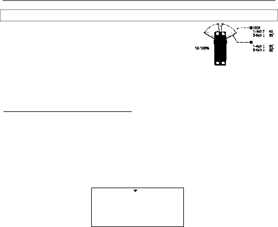
Aircraft (ACRO) Section
– 41 –
Airplane Model Function Descriptions
EPA — End Point Adjust
The EPA function is used to set (or limit) the travel of each servo,
and may be set anywhere from 0% and 125% for each travel
direction. Reducing the percentage settings reduces the total servo
throw in that direction. The EPA function is normally used to
prevent any servos from binding at the ends of their travel. If you
change the EPA setting to 0%, you will not have any servo response in that direction, and
will probably crash.
Setting EPA values on your system:
1. Enter the programming mode by pressing the two Edit Up Down keys (the two keys on the far
left) at the same time. You should pop right into the EPA screen, but if you do not, press
either Edit Up Down key until you see EPA displayed. The channel indicator is above
numeral 1 for ailerons, the percent symbol will be flashing, and you’ll notice that you can
change the L/U indicator to R/D (or vice versa) by moving the aileron (right) stick. In the next
steps you will see how you set the travel directions independently for each stick (or knob or
gear switch) motion.
EPA 100
CH 4213567
L/U %
2. To set the RIGHT aileron servo travel, move the aileron stick all the way to the right and hold
it. The letters “R/D” should appear next to the flashing percent sign, meaning you are setting
either Right or Up travel (with ailerons it’s right or left only, but the display is set up to use
the same indicators for elevator and throttle, thus the dual meanings for the letters). Now if
your servo is stalled or binding, you’ll hear a buzzing sound. Hit the Data –Decrease key until
the buzzing stops. If the servo is not buzzing, leave the setting at 100%. Later, depending on
how rapidly the model rolls, you can use aileron dual rates to reduce the sensitivity.
3. To set the LEFT aileron motion, move the aileron stick all the way to the left and hold it. The
letters “L/U” should appear next to the flashing percent sign. Again listen and hit the Data –
Decrease key until the buzzing stops. If the servo is not buzzing, leave the setting at 100%.
4. To set travel volumes for other channels, press the Cursor Right key to select the channel you
wish to change. The little triangle moves and indicates the active channel. Repeat these
steps with each channel in sequence, taking care to set the travel for both directions. You

Aircraft (ACRO) Section
– –
42
may set each channel separately, anywhere in between 0% and 125%, and if you wish to
rapidly return to the default 100% setting, press the Active/Inhibit (Clear) key.
5. Return to the regular operating mode by pressing the two Edit Up Down keys simultaneously.
Congratulations! You’ve successfully programmed your system!
D/R — Dual Rates
If this is your first computer radio, you may have never been introduced to dual rates
before. Dual rates are used because most models respond more rapidly to control inputs while
they’re flying at higher speeds, and it is possible to be really gentle with the controls and yet still
over-control. Dual rates are used to adjust the transmitter so that a control actuated at high speed
will not cause a radical response, so they are very useful for beginning pilots as well as experts.
Dual rates are invoked by flipping the dual rate switches on the transmitter. The Eclipse
7 has three dual rate switches, one each for ailerons, elevator, and rudder. The aileron dual rate
switch is located over the right-hand stick; the elevator dual rate switch is located over the left-
hand stick, and the rudder dual rate switch is to the right of the elevator switch. The amount of
travel reduction or increase may be set anywhere between 0 and 125%. Note: if you set the
dual rate amount to zero, you will get no response from that channel, which may cause a
crash.
If you have flight conditions active, you can select different amounts of dual rates for
each flight condition.
Inputting Dual Rate Values
1. Get to the D/R screen with the Edit Up Down keys.
2. The active channel number is indicated by the arrow above or below the channel numbers.
The arrow’s position depends on the position of that channel’s dual rate switch. In the figure,
the aileron (CH1) dual rate setting at the D/R switch’s lower position is being programmed.
D/R 100
CH
%
ST1
421
ST2 ST3 NOR
3. Use the Data +Increase or –Decrease key to choose the amount of dual rate for that switch
position. You may set the travel for both sides of the switch simply by flipping the switch to
the other position (the arrow will also switch sides). If you wish to return to the original
100% value, press the Active/Inhibit (Clear) key.
4. Press the Cursor Right key to move to another channel you wish to input dual rate settings.
Aircraft (ACRO) Section
– 43 –
5. Repeat the first three steps for the dual rate settings on the remaining channels. Note that
you can leave one side of the dual rate switches alone. This can be used for exponential
settings (see next function).
6. Return to the regular operating mode by pressing the two Edit Up Down keys simultaneously.
EXP — Exponential
You may be new to exponential settings. “Exponential” refers to a mathematical function
where the curve grows steeper the further away from center it gets. Expo is a way to get the
effect of dual rates without having to flip a switch. The figure below will help explain this
concept.
Normal
linear
response
Exponential gives
smaller response for
same stick motion
around neutral
Stick Motion
Servo
Response
Much less response
around neutral (compare
with Normal line)
Increasing
exponential
(shallower around
neutral)
25%
0% (Linear)
50%
75%
You will notice that exponential has a smooth curve. For this reason it is possible to have
low sensitivity at low stick angles (like dual rates), and yet have full motion at full stick
deflection. The Eclipse 7 allows you to have two different values of exponential, chosen by the
same dual rate toggle switches on the transmitter, described earlier. You might want to set a dual
rate at one switch position with zero exponential, and an exponential value with 100% dual rate
at the other. Then you can switch between them in flight and decide which you like better.
Later, you can combine both dual rate settings and exponential on a single switch setting.
There are really two kinds of exponential, “positive” and “negative.” Negative
exponential is the one shown above, and the type of expo most commonly used, where servo
movement is softer around neutral. Positive exponential is where the servos are very sensitive
around neutral and soft at extremes. It is sometimes used for helicopter tail rotors.
The Eclipse 7 allows you to set exponential for ailerons, elevator, and rudder. If you
have flight conditions active, you can select different amounts of expo for each flight condition.
Setting Exponentials
1. Enter the programming mode by pressing the two Edit Up Down keys (the two keys on the far
left) at the same time. Press either Edit Up Down key until the EXP menu appears, as shown.

Aircraft (ACRO) Section
– –
44
EXP -30
CH 421
%
ST1 ST2 ST3 NOR
2. To set exponential for channel 1, move the arrow by pressing the Cursor Right or Left keys
repeatedly until the arrow is under or over the channel number you want. Now switch the
appropriate switch up or down, noticing the position of the arrow. You can set two values of
exponential, one for each switch position. By pressing the Data +Increase or –Decrease keys,
you can add or subtract from the numerical value displayed. Note that you may pick a value
anywhere from –100% to +100%. If you quickly want to get back to the default 0%, press
the Active/Inhibit (Clear) key. You should understand that you won’t see changes in your
model’s servo response unless you move the sticks. To get a feel for how exponential works,
just hold partial stick and switch the Expo on and off (one side of the switch should be set to
zero expo). You’ll see how it affects the servo travel.
3. The values you set for exponential are highly dependent on both the model and pilot’s
preference. I normally recommend a start value of about –10% to -20%, and many test
flights, slowly increasing the number until things are “right”. Obviously this depends on the
pilot and model so go ahead and fly it with Expo only on one side of the switch, turn it on and
off during flight, and change things to suit yourself. Or don’t use it at all if you don’t like it
— it’s not for everyone.
4. Repeat this procedure for the expo settings on the other remaining channels.
5. Return to the regular operating mode by pressing the two Edit Up/Down keys simultaneously.
FLT.C — Flight Condition Menu
Flight conditions are special functions which allow you to switch certain settings in the
Eclipse 7 transmitter in order to tailor it to different conditions of flight. For example, you might
have a scale model which is very sluggish at lower speeds (such as takeoff and landing) yet is
very sensitive at higher speeds. Or, it may need lots of rudder trim at lower speeds, but not at
higher speeds. Flight conditions allow you to choose between up to three different individual
sets of trims, dual rate settings, and exponential values. You make the change when either the
Flt. Mode (upper left, 3-position switch) or Flt. Cond. (upper right, long arm, rear of transmitter)
switch is flipped.
The Eclipse 7 provides three flight conditions in addition to the normal one (NOR),
denoted ST1, ST2, and ST3 (you will see these indicators in the display). Flight conditions are a
Aircraft (ACRO) Section
– 45 –
very unusual feature for a system in the class of the Eclipse 7 and they are normally found only
on systems costing far more. As you learn to use them, you will really appreciate them.
The priority of the conditions (when all three are activated) is as follows: ST3 > (ST1,
ST2) > NOR. In words, whenever ST3 is turned on, it has priority over the other conditions. If
ST3 is not on, both ST1 and ST2 override NOR, which is only active if all the others are turned
off. This is better understood if you look at the table below:
Aircraft (ACRO) Section
– –
46
Flt. Mode Switch Flt. Cond Switch Active Flight Cond. Comments
Any position Forward ST3 ST3 overrides all
Forward Back ST2 ST2 active if ST3 off.
LAND also on.
Back Back ST1 ST1 active if ST3 off.
(E->F on)
Center Back NOR Default condition
Choosing Flight Conditions
1. Get to the FLT.C screen with the Edit Up Down keys. The display will indicate “Inh” and,
depending on the positions of the two controlling switches, one of the condition displays on
the bottom (ST1, ST2, or ST3) may be flashing.
FLT.C On
ST1 ST2 ST3
flashing
2. Select the desired flight condition from the third column of the table above, and move the
two switches to the positions shown on the same row of the table. The active condition
indicator on the bottom right of the display will flash.
3. Activate the selected flight condition by pressing the Active/Inhibit (Clear) key. The letters
“Inh” will change to “On”. Note that you cannot activate ST1 or ST2 if the Flt. Cond switch
is forward, even if ST3 is currently inhibited.
4. Repeat this procedure to activate each desired flight condition. You can activate up to three
conditions (besides the normal one, which is always on). In this display, you can tell if you
are in the NOR mode if the display indicates “Inh” and ST1, ST2, and ST3 are NOT
flashing.
5. Verify that the desired flight conditions operate when the appropriate switch combination is
selected by looking at the flashing displays.
6. Now that you have activated one or more flight conditions, you can have new sets of dual
rates, exponential values, and trims. Trims are defined by the trim levers on the transmitter,
but you can define the values of D/R and Expo using the programming menu. Use the Edit
Up Down key to move to the D/R menu.
7. With D/R indicated in the display, be sure the flight condition switches are in the desired
position by checking to see which is flashing. Then input the desired D/R value for the active
condition. Note that you can only define one rate for each flight condition — the position of
the Dual Rate switches does not matter.
Aircraft (ACRO) Section
– 47 –
8. Again use the Edit Up Down keys to get to the Expo menu, and set up a desired value of expo
for each flight condition. Again, you can only select one exponential value for each flight
condition.
9. Return to the regular operating mode by pressing the two Edit Up Down keys simultaneously.
If you move to the TRIM menu with the Edit Up Down key, the flight condition indicators are
shown in the lower right of the screen, to tell you which is active. You can change the trims
in one flight condition, and they are stored separately and called up with you switch between
them. That’s really cool!
STRM — Subtrim Settings
The Subtrim window is used to make small adjustments or corrections in the neutral
position of each servo, independent of the trim levers. The recommended procedure is to zero
out both the trims (see settings menu) and the subtrims (this menu). Then, one mounts the servo
arms and sets up linkages so that the neutral position of each control surface is as close to where
it should be as possible, with the arm 90° to the pushrod. Finally, small amounts of subtrim are
used to make fine corrections. We recommend that you try to keep all of the subtrim values of
as small as possible. Otherwise, when the subtrims are large values, the servo’s full range of
travel may be restricted.
Setting Subtrims
1. Use the Edit Up Down keys to call up the STRM window.
STRM 5
CH 4213567
2. Press the Cursor Right or Left key until the small arrow is above the channel you wish to
adjust (the figure shows subtrim adjustment for CH1).
3. Adjust the neutral position using the Data +Increase or –Decrease keys. You may adjust
between -100% and +100%. If you want to reset the value back to zero, press the
Active/Inhibit (Clear) key.
4. Repeat steps 2 and 3 for each channel to be adjusted in turn.
5. Return to the regular operating mode by pressing the two Edit Up Down keys simultaneously.
REV — Servo Reversing
The servo reverse function may be used when you need to change the direction that a
servo responds to a control stick motion. When you use this function, BE SURE THAT YOUR
CONTROL IS MOVING THE CORRECT DIRECTION. If you are using any preprogrammed
Aircraft (ACRO) Section
– –
48
mixers such as flaperon, be sure to set correct travels in the REV menu setting up the
preprogrammed function.
Reversing Servos
1. Get to the REV screen with the Edit Up Down keys.
2. Use the Data +Increase or –Decrease key to select the channel you wish to reverse. The
active channel number will flash.
REV
CH 421 3 567
N
R
3. Toggle between normal (N) and reverse (R) with the Active/Inhibit (Clear) key. The arrow
above the number indicates normal travel, while the arrow below indicates reversed travel
(the figure shows all channels normal, none reversed).
4. Repeat this procedure for each channel needing to be reversed.
5. Return to the regular operating mode by pressing the two Edit Up Down keys simultaneously.
T.CUT — Throttle Cut (Engine Kill) Function
The Throttle Cut function provides you an easy way to stop the engine by simply
pressing a button with the throttle stick at idle, which commands the throttle servo to move a
prescribed amount. The throttle servo moves to the selected cut position when the Cut button is
pressed and the throttle stick is below 50%. Above 50% throttle, the cut button has no effect.
The activation direction may be chosen by the owner.
Setting up the Throttle Cut function
1. Get to the T.CUT screen with the Edit Up Down keys.
2. Place the throttle at its idle position (towards bottom of transmitter). Use the Data –Decrease
key to select the amount of motion of the throttle servo you wish — normally you want to
completely close the carburetor, but be careful not to choose too much travel which will stall
the servo. You may see the servo move when you press the Active/Inhibit (Clear) button. A
maximum of 72% may be chosen, but only use the amount you need to fully close the
carburetor without stalling the servo.(Picture : Need !over 3)
T.CUT -14
CH
%
3flashing
3. Return to the regular operating mode by pressing the two Edit Up Down keys simultaneously.
Aircraft (ACRO) Section
– 49 –
PMX1 to PMX5 — Programmable Mixes 1, 2, 3, 4, & 5
Your Eclipse 7 system contains FIVE separate programmable mixers (PMX1 — PMX5)
with unique capabilities. You may use mixing to correct unwanted tendencies of the aircraft
during aerobatics. Each one of these mixers may be programmed to do things that are not built-
in programs. This makes them useful for all sorts of different things. Note that the mixers must
be turned on by flipping a switch — if you need them to be on all the time, you must not touch
that switch.
The elevator dual-rate switch in its down position turns on mixers (if they’ve been
activated). The method to be used to program mixers is given for Mixer #1, but the other mixers
may be programmed in an identical fashion.
You can use both PMXs to create a custom dual elevator function, where you use two
servos for your elevator control, one for each side, the second plugged into an unused receiver
channel and mixed from elevator (if you do this, you must be careful to keep the mixer on at all
times). Or you may also use the mixers for correcting unwanted flying tendencies, like
automatically applying a bit of rudder with throttle to account for torque/P-factor effects, to a
corrective elevator motion during knife-edge flight to correct for an undesired tucking tendency
(the latter is described in the ACRO model setup section and below).
Using the Programmable mixers
1. Call up the mixer screen by repeatedly pressing one of the Edit Up Down keys until a PMX
window appears. The default is for the function to be inhibited. To activate, press the
Active/Inhibit (Clear) key. This will cause the INH display to change to a display showing
100%, Master and Slave indicators, and a flashing ON or OFF depending on the position of
the mixer's on-off switch (see table below).
PMIX1 + 8
CH
%
ON R/D
4213567
SLV
MAS
2. Now you’ll select the Master channel for the mixing, the channel that causes the mixing to
occur. Press the Cursor Right key to get the master channel indicator MAS flashing on and
off, then press the Data +Increase or –Decrease keys to move the top arrow over the number
of the desired master channel, 1 – 7.
421356
CH Master
Slave
3. Next you’ll put in the Slave channel, the one that is affected by motion of the master
channel. Press the Cursor Right key to get slave channel indicator SLV flashing on and off,
then press the Data +Increase or –Decrease keys to move the bottom arrow underneath the
number of the desired slave channel.

Aircraft (ACRO) Section
– –
50
• Now we'll input the mixing percentage, which tells how much the slave channel responds to
the master channel. Press the Cursor Right key to cause the percent (%) sign to the right of
the large number to flash on and off. Note that you can set the percentage for the mixer on
each side of the master channel’s control’s motion by moving the master channel's control
back and forth. The motion of the master channel's control is also indicated by the R/D (=
Right/Down) or L/U (= Left/Up) indicator in the window.
• Hold the master channel's control to one side, and then use the Data +Increase or –Decrease
key to change the percentage for the mixer. Verify that you get the proper motion of the
slave channel when you move the master. If you don't get a response to the master
movement, check that the mixer is turned on with its on-off switch (either the Ch. 7 switch,
or the Rudd D/R switch). Change the percentage if the amount of travel is incorrect. If you
want to set the percentage to ZERO, press the Active/Inhibit (Clear) key.
6. Move the master control to the other side of its travel and then repeat the actions in the
previous step to set the amount of mixing on the other side. Use the Data +Increase or –
Decrease key to change the percentage for the mixer until you get the response you want for
the second side.
[Knife-Edge Example: for a model that tucks during knife-edge flight, set up a mixer with
Master = 4 (Rudder), and Slave = 2 (elevator). You want to get up elevator mixed in for either
direction of full rudder. Therefore, you’ll set plus mixing on one side of the rudder stick, and
minus mixing on the other side. Normally only 5% to 10% mixing is needed to solve this
problem. Mixer No. Mixer On When … Available menus
1 CH7 Switch Down ACRO, GLID
2 CH7 Switch Down ACRO, GLID
3 Gear Switch Down ACRO, GLID, HELI
4 Rudder Switch Down ACRO, GLID, HELI
5 Flt Condition Switch Down ACRO, GLID
LAND — Landing Function
The LAND function simultaneously moves the flaps and the elevator to defined positions to
help make steep descents or limit airspeed in dives. The controls move to the defined positions
by flipping the Flt. Mode switch fully forward.
If your model has a single flap servo on CH6, the flap is dropped. If flaperons are active,
you’ll want to raise both to prevent tip-stalling with some up-elevator to compensate, but you
may want to experiment with small values of down flaperons to slow the model down. Use the
elevator offset to maintain pitch trim when the landing function is turned on.
Aircraft (ACRO) Section
– 51 –
Setting up Landing function
1. Use the Edit Up Down arrow keys to select the LAND window. Depending on the position of
the landing switch, the display will show a flashing OFF or ON. The Flt. Mode switch turns
on LAND when all the way forward.
LAND 0
CH
%
OFF ON 26
2. First the amount of elevator offset is programmed. A small arrow is displayed over the
numeral 2 (representing elevator). You may adjust the amount of travel with
the Data +Increase and –Decrease keys. You may use anywhere between -
100% and +100%, but a small value of ±10% or less is the recommended starting value. Be
careful as this has a very powerful effect on the model’s trim. Press the Active/Inhibit (Clear)
key if you wish to reset to 0%.
3. To get to the flap travel setting, press the Cursor Right key. The small triangle
is now displayed above the numeral 6, indicating the flap channel. You may
input any desired flap travel with the Data +Increase and –Decrease keys. The default is 0%,
and you may set this anywhere from -100 to +100% (check that there is no binding with large
flap deflections and aileron commands). With flaperons, large motions should also be
avoided because of reduced aileron effectiveness. You may return to the 0% settings by
hitting the Active/Inhibit (Clear) key.
Note: At first, be very cautious using the LAND function when you are flying slowly, as there
could be a loss of roll authority. Check out how it works at high altitude first.
FLPT — Flap Trim Function
The Flap Trim function is used to specify the amount of flap travel produced by motion of
the flap control (the CH6 knob). With flaperons active, it controls the motion of both ailerons.
Setting Flap Trim function
1. Use the Edit Up Down arrow keys to select the FLPT window.
FLPT 20
CH 6
2. Pressing the Data +Increase or –Decrease key to input your desired flap motion setting. The
30% default value produces “reasonable” travel for many models, but you must try it out on your
own model to be sure. A 100% setting causes extreme travel and is not recommended. You may
want to set it to a smaller number, say 10% for starters. If you wish to return to the default 30%
CH 26
CH 26
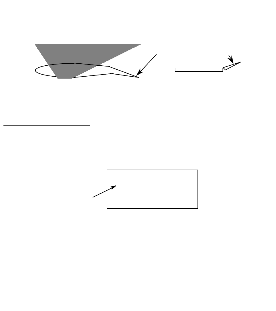
Aircraft (ACRO) Section
– –
52
setting, press the Active/Inhibit (Clear) key. You can toggle through the settings 0%, 30%, and
100% by continuing to press this key. Setting it to 0% disables the flap knob, but the flaps will
still respond to mixing functions such as E->F and to the Landing function.
E->F — Elevator →
→ →
→ Flap Mixing
Elevator-to-flap mixing makes the flaps drop or rise whenever you pull on the elevator
stick. It is used to make tighter “pylon” turns or squarer corners in maneuvers. Elevator-to-flap
mixing is set up so that the flaps droop (are lowered) when up elevator is commanded.
UP elevator
DOWN flap or
flaperon
Notice that this mixing function works with the flaperon setting. If flaperon mixing
(FLPN) AND E->F mixing are activated, when you pull up elevator, BOTH ailerons will droop.
This function is turned on with the Flt. Mode switch fully Back.
Setting Up E → F Mixing
1. Press one of the Up Down Edit buttons until the E->F window appears. The default is for the
function to be inhibited. To activate, press the Active/Inhibit (Clear) key. This will cause the
INH display to change to a number display, and either ON or OFF will be flashing depending
on the position of the Flt. Mode switch (fully back turns it ON).
E->F 30
R/D %
ON
ON or OFF
depends on
Flt. Mode
switch
setting
2. Press the Cursor Right key to get the percent sign flashing, then press the Data +Increase and
–Decrease keys to increase or decrease the amount of mixing. Check the direction the flaps
move with elevator stick: with up elevator, the flaps should droop downwards, and for down
elevator they should come up. In other words, they should move opposite the elevator
motion. If they don’t, use the Data +Increase and –Decrease keys to change the sign in front
of the percentage number. You should probably start with a smaller number (say 20% or so)
and slowly increase it to learn how the model reacts. Remember the position of the Flt.
Mode switch turns this function on and off (fully back turns it ON).
A->R — Aileron →
→ →
→ Rudder Mixing
Aileron-to-rudder mixing is a function which causes the rudder to move automatically
with the motion of the aileron stick. This is done because when ailerons are used to command a
turn, the down-moving aileron has more drag than the up-moving one, so the plane’s fuselage
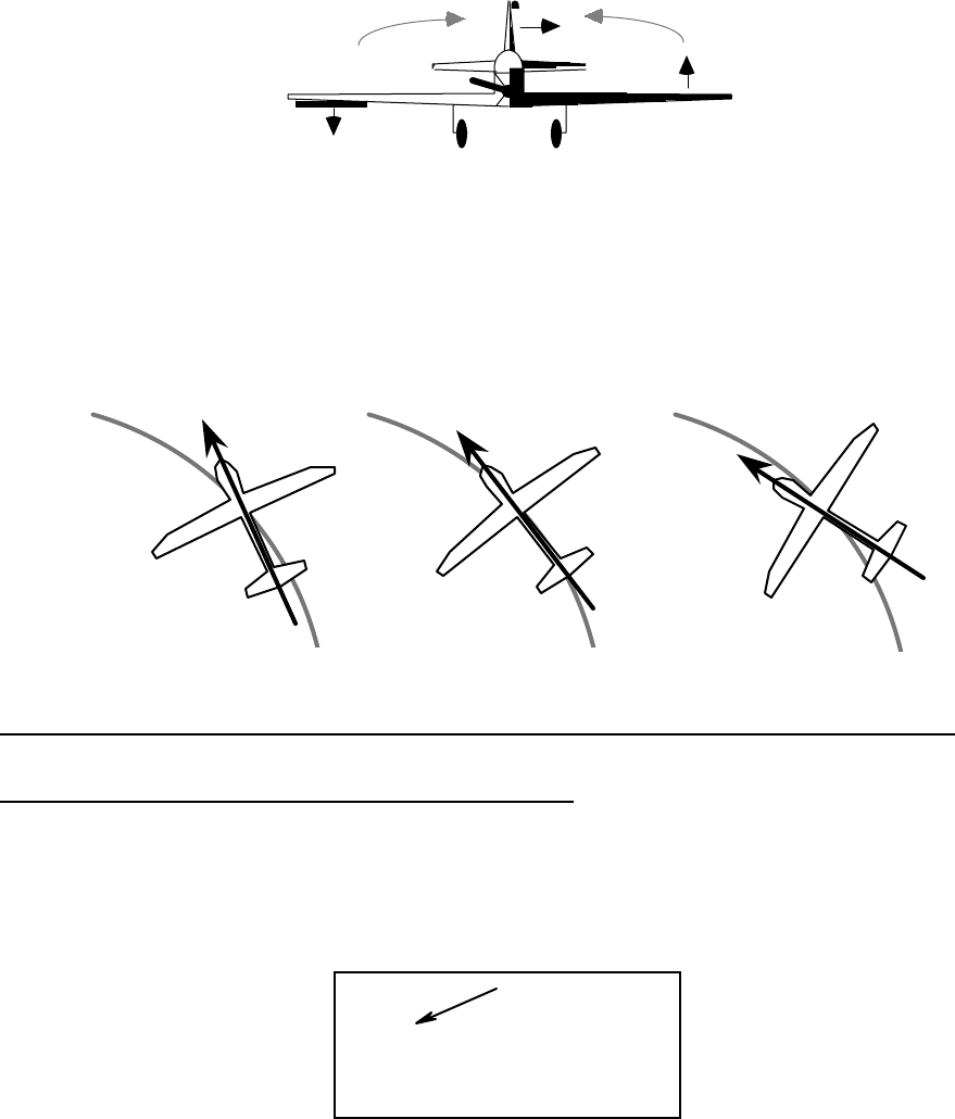
Aircraft (ACRO) Section
– 53 –
tries to yaw against the turn. Adding rudder mixing cures this problem by making the fuselage
point straight into the oncoming air stream (this is also called “coordinating the turn”).
The slower the model flies, the more mixing is needed, and the faster it moves, the less is
needed. It is ideal to make slow-flying scale models fly realistically. The amount of coupling is
highly dependent on the model configuration. Usually only a small amount of rudder is needed.
It will also help to set up some aileron differential using the EPA menus. A good starting point is
to limit the ailerons' down motion to 50% to 75% of the up-moving aileron's motion.
The aileron-to-rudder mixing function is turned on and off by the Rudder D/R switch.
Coordinated turn: fuse
lines up with turn direction
(don't change anything!)
Nose points inside circle : too
much coupling or differential.
Reduce one or both.
Nose points outside
circle: increase coupling
and/or differential
Setting Up A->R Mixing (Rudder Coupling)
1. Press one of the Up Down Edit buttons until the A->R window appears, as shown. The
default is for the function to be inhibited, as shown. To activate, press the Active/Inhibit
(Clear) key. The letters “INH” will turn to “0,” and either the ON indicator or the OFF
indicator will be flashing, depending on the position of the Rudder D/R switch.
A->R 10
R/D %
ON
flashing
2. Press the Cursor Right key once, and the Percent sign will be flashing. Move the aileron
stick all the way to the right, and adjust the R/D mixing amount by pressing the Data
+Increase or –Decrease key. You may set any amount between 0 and 100% (an initial value
of 10-20% is suggested). To return to the initial 0% value, press the Active/Inhibit (Clear) key.
3. Move the aileron stick all the way to the left, and adjust the L/U mixing amount in the same
way. To return to the initial 0% value, press the Active/Inhibit (Clear) key.
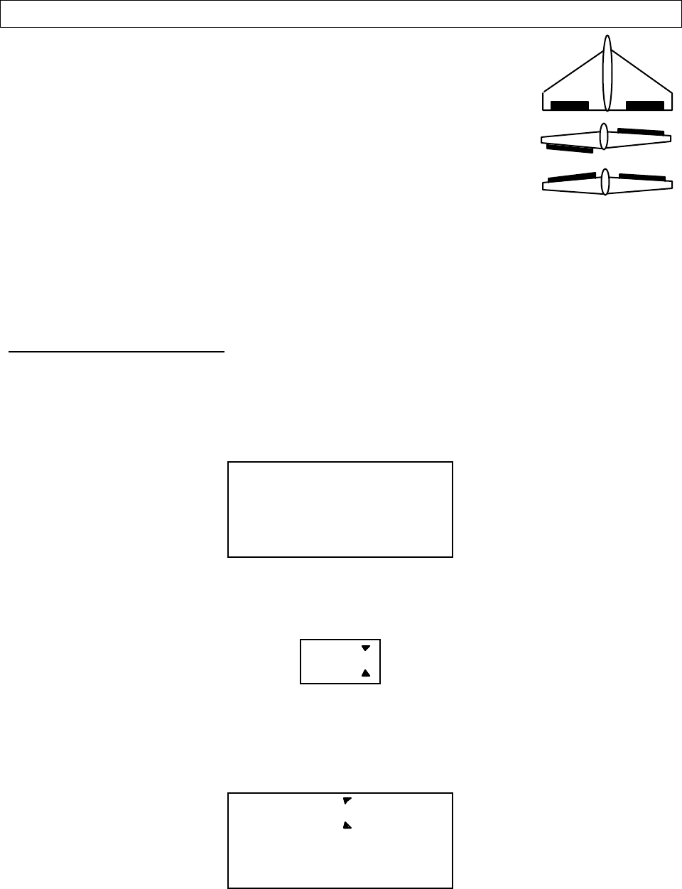
Aircraft (ACRO) Section
– –
54
ELVN — Elevon Mixing
The Elevon function should be used with delta wings, flying wings,
and other tailless aircraft whose layouts combine the aileron and elevator
functions, and requires one servo for each elevon. Connect the right elevon
to receiver CH1 and the left elevon to CH2.
The amount of aileron and elevator response can be adjusted
independently. However, if you program in too much elevator or rudder
travel, the servos may reach their travel limits before full stick motion has
occurred. The default values for this mixer are 100%, but you may want to
keep the travel settings at 50% or below because most elevon planes are very sensitive, and
adjust the control linkages to get the travel you desire. Note that you cannot use either flaperon
or V-tail mixing when elevon mixing is active.
Setting up elevon mixing
1. The right elevon should be plugged into CH1, and the left elevon should be plugged into
CH2.
2. Press one of the Up Down Edit buttons repeatedly to select the ELVN window.
3. To activate, press the Active/Inhibit (Clear) key. The letters “INH” will turn to “On.”
ELVN On
CH 12
SLV
MAS
4. Press the Cursor Right key once, to get to the elevator travel setting menu. A small arrow is
displayed over the numeral 2 represents elevator master channel, and the percent indicator
will blink on and off. The little arrow below the 2 indicates left elevon is being set.
CH
N
R21
SLV
MAS
5. Move the elevator stick all the way to the back (full up position): both elevons should move
upwards like elevators. If the left (CH2) elevon moves down, change the its travel direction
by pressing the Active/Inhibit (Clear) key to get 0% quickly, then pressing the Data –
Decrease key until you reach -50%.
ELVN -50
CH
N21
SLV
MAS
%
CH1 CH2
Aileron operation
Elevator operation
Aircraft (ACRO) Section
– 55 –
6. If the right (CH1) elevon moves down with up elevator stick, change the its travel direction
by pressing the Cursor Right key (the little arrow moves under the 1), then press the Data –
Decrease key until you reach -50%. Otherwise, continue.
7. Now you’ll input the amount of aileron stick response on the right (CH1) elevon by pressing
the Cursor Right key once. Now the little arrows move both over and under the 1, and you
may adjust the amount of right elevon travel with the Data +Increase and –Decrease keys.
50% is a good starting point. As before, change the sign and use -50% if it travels the wrong
way with aileron stick.
CH
N
R21
SLV
MAS
8. Now you’ll input the amount of aileron stick response on the left (CH2) elevon by pressing
the Cursor Right key once. Now the little arrow moves under the 2, and you may adjust the
amount of left elevon travel with the Data +Increase and –Decrease keys. 50% is a good
starting point. Change the sign if travel needs to be reversed.
CH
N
R21
SLV
MAS
VTAL — V-Tail Mixing
V-tail mixing is used with V-tail aircraft so that
both elevator and rudder functions are combined for
the two tail surfaces, called “ruddervators.” The
response to both elevator and rudder inputs can be
adjusted independently. However, if you program in too much elevator or rudder travel, when
both rudder and elevator are commanded the servos may reach their travel limits before full stick
motion has occurred. Therefore, you should keep the travel settings at 50% or below and adjust
the control linkages to get the travel you desire. Note that you cannot have both V-tail and
elevon mixing active at the same time.
Setting up V-Tail mixing
1. The right ruddervator should be plugged into CH2, and the left ruddervator should be
plugged into CH4.
2. Press one of the Up Down Edit buttons repeatedly to select the VTAL window. The INH
indicator will show.
3. Press the Active/Inhibit (Clear) key to activate the V-tail function. The display will show On.
CH2 CH4 CH2 CH4
Up Elevator Left Rudder (view from rear)
Aircraft (ACRO) Section
– –
56
VTAL On
CH 42
SLV
MAS
4. Press the Cursor Right key once, to get to the elevator setting menu. A small arrow is
displayed over the numeral 2, representing elevator master channel, and under the numeral 2,
indicating the right (CH2) ruddervator, and the percent indicator will blink on and off. Move
the elevator stick all the way to the back (full up position): both ruddervators should move
upwards. If the right (CH2) ruddervator moves down, change the its travel direction by
pressing the Active/Inhibit (Clear) key, then pressing the Data –Decrease key until you reach -
50%.
CH
N
R42
SLV
MAS
5. If the left (CH4) ruddervator moves down with up elevator stick, change the its travel
direction by pressing the Cursor Right key (the bottom arrow moves under the 4), the
Active/Inhibit (Clear) key (sets 0%), then press the Data –Decrease key until you reach -50%.
Otherwise, continue.
CH
N
R42
SLV
MAS
6. Now you’ll input the amount of rudder stick response on the left (CH4) ruddervator by
pressing the Cursor Right key once. Now the little arrows move both over and under the 4,
and you may adjust the amount of left ruddervator travel with the Data +Increase and –
Decrease keys. 50% is a good starting point. Press Active/Inhibit (Clear) key if you wish to
reset to 0%).
CH
N
R42
SLV
MAS
7. Now you’ll input the amount of rudder stick response on the right (CH2) ruddervator by
pressing the Cursor Right key once. Now the little arrow moves under the 2, and you may
adjust the amount of right ruddervator travel with the Data +Increase and –Decrease keys.
50% is a good starting point. Press Active/Inhibit (Clear) key if you wish to reset to 0%).
CH
N
R42
SLV
MAS
8. Remember to be sure not to have so much travel as to cause binding when both elevator and
rudder are commanded simultaneously.
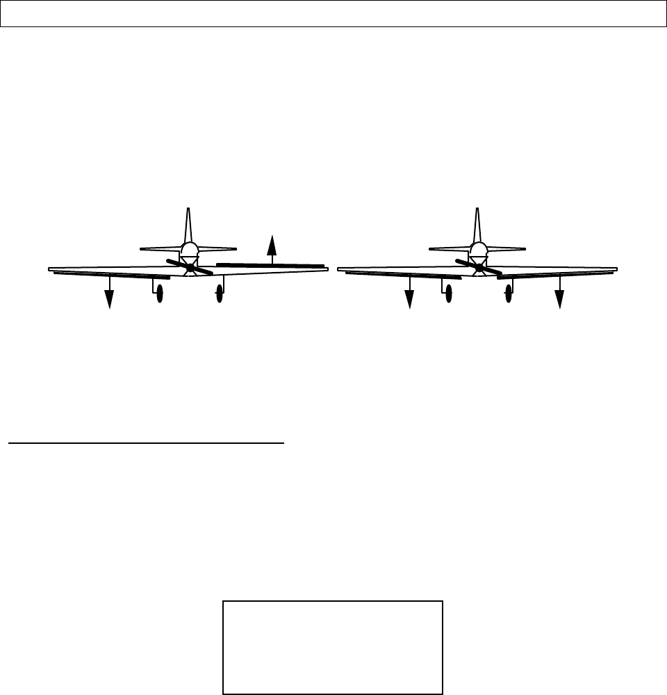
Aircraft (ACRO) Section
– 57 –
FLPN — Flaperon Mixing
The Flaperon mixing function uses two servos to individually control two ailerons,
combining the aileron function with the flap function. Both ailerons can be raised and lowered
simultaneously for a flap effect. Of course, aileron function, where the two controls move in
different directions, is also performed. The down travel of the left and right ailerons can be
adjusted, so you can also get a differential effect. (Left and right flap travel are adjusted
individually in the EPA menu.) To take advantage of the flaperon mixing function, you’ll need
to connect the right aileron servo to CH1 (AIL) and the left aileron servo to CH6 (FLP).
Aileron Operation Flap Operation
Ch 1 Ch 6 Ch 6
Ch 1
You can combine the flaperon function with the landing function (LAND), to get steeper
descents without building up airspeed. This is very convenient for making short approaches on
small fields. Note that you cannot have both flaperon and elevon mixing active at the same time.
Setting up the Flaperon function
1. The right flaperon servo should be plugged into CH1, and the left flaperon servo should be
plugged into CH6.
2. Press one of the Up Down Edit buttons repeatedly to select the FLPN window. The INH
indicator will show.
3. Press the Active/Inhibit (Clear) key to activate the flaperon function. This will show the On
indicator.
FLPN On
CH 16
SLV
MAS
4. Press the Cursor Right key once. A small arrow is displayed over the numeral 1, representing
aileron master channel, and the percent indicator will blink on and off. A small arrow is
displayed under the numeral 1, which tells us we’re setting the right (CH1) flaperon servo.
Move the aileron stick all the way to the right, and check that both flaperons move the right
direction. If the right (CH1) flaperon moves the wrong way, change the its travel direction
by holding the stick to the right, pressing the Active/Inhibit (Clear) key, then pressing the Data
–Decrease key until you reach -100%. This will also change the travel for the left stick
motion.
Aircraft (ACRO) Section
– –
58
FLPN +100
CH
%
16
SLV
MAS
5. If the left (CH6) flaperon moves correctly with aileron stick, go to the next step. Otherwise,
change the its travel direction by pressing the Cursor Right key (the little arrow moves under
the 6), press the Active/Inhibit (Clear) key (sets 0%), then press the Data –Decrease key until
you reach -100%.
CH
N
R61
SLV
MAS
6. Now you’ll input the amount of flap response on the flaperons. The flap motion is
commanded by the VR1 knob to the left of the antenna, and both flaperons should move the
same direction when you move the knob. Press the Cursor Right key one time, so the little
arrow moves over the 6 indicating flaps are now the master channel. Note the arrow under
the 6 as well, indicating left (CH6) flaperon. Now you may adjust the amount of left flaperon
travel with the Data +Increase and –Decrease keys. Press Active/Inhibit (Clear) key if you wish
to reset to 0%). You may need to choose negative values to get the control to travel the
correct direction.
CH
N
R61
SLV
MAS
7. Now you’ll input the amount of flap knob response on the right (CH1) flaperon by pressing
the Cursor Right key once. Now the little arrow moves under the 1, and you may adjust the
amount of right flaperon travel with the Data +Increase and –Decrease keys.
CH
N
R61
SLV
MAS
8. You may wish to set aileron differential. Aileron differential means that each aileron has
more travel in the ‘up’ direction than the ‘down’ direction. Normally the down travel is
reduced to about half of the up travel, especially on slower-flying models. Press the Cursor
Right key two times, so the little arrows move over and under the 1 indicating aileron stick is
again the master channel. The arrow under the 1 indicates the right (CH1) flaperon. Move
the stick to the LEFT and press the Data –Decrease key until you get to 50-75%. If you need
even more differential, you can choose as low as 0% down, and the ailerons will move up
only. This is preferred over reducing the up travel, which reduces the roll rate.
Aircraft (ACRO) Section
– 59 –
9. You must repeat this procedure for the left flaperon also. Press the Cursor Right key one
time, so the little arrow moves under the 6 indicating the left (CH6) flaperon. Move the stick
to the Right and as before, press the Data –Decrease key until you get to 50-75%.

Aircraft (ACRO) Section
– –
60
Aircraft Flight Trimming Chart
The following chart may be used to systematically set up and trim a model for straight flight and
aerobatic maneuvers. Please note that for best results, trimming should be done in near-calm
conditions. Before you decide to make a change, be sure to try the test several times before
making adjustments. If any changes are made, go back through the previous steps and verify that
they are not also affected. If they are, make further adjustments as necessary.
To test for … Test Procedure Observations Adjustments
1. Control
neutrals Fly the model straight and level Use the transmitter trims for hands-off
straight & level flight. Change electronic subtrims or
adjust clevises to center
transmitter trims.
2. Control throws Fly the model and apply full
deflection of each control in
turn
Check the response of each control
• Aileron high-rate: 3 rolls in 4 seconds;
low-rate: 3 rolls/6 sec
• Elevator high-rate: to give a smooth
square corner; low-rate gives approx.
130 ft diameter loop
• Rudder: high-rate 30-35° for stall turns;
low rate maintains knife-edge
Change EPA (for high rates),
and Dual Rate settings (for
low rates) to achieve desired
responses.
3. Decalage Power off vertical dive
(crosswind if any). Release
controls when model vertical
(elevator trim must be neutral)
A. Model continues straight down
B. Model starts to pull out (nose up)?
C. Model starts to tuck in (nose down)?
A. No adjustment
B. Reduce incidence
C. Increase incidence
4. Center of
Gravity Method 1: Roll into near
vertically-banked turn.
Method 2: Roll model inverted
A1. Nose drops
B1. Tail drops
A2. Lots of forward stick (down
elevator) required to maintain level
flight
B2. No forward stick (down elevator)
required to maintain level flight, or
model climbs
A. Add weight to tail
B. Add weight to nose
5. Tip weight
(coarse
adjustment)
Fly model straight & level
upright. Check aileron trim
maintains level wings. Roll
model inverted, wings level.
Release aileron stick.
A. Model does not drop a wing.
B. Left wing drops.
C. Right wing drops.
A. No adjustment
B. Add weight to right tip.
C. Add weight to left tip.
6. Side Thrust &
Warped Wing Fly model away from you into
any wind. Pull it into a vertical
climb, watch for deviations as
it slows down.
A. Model continues straight up.
B. Model veers left
C. Model veers right
D. Model rolls right
A. No adjustment
B. Add right thrust
C. Reduce right thrust
D. Put trim tab under left
wing tip *
7. Up/Down
Thrust Fly the model on normal path
into any wind, parallel to strip,
at a distance of around 100
meters from you (elevator trim
should be neutral as per Test
3). Pull it into a vertical climb
& neutralize elevator
A. Model continues straight up
B. Model pitches up (goes toward top of
model)
C. Model pitches down (goes toward
bottom of model)
A. No adjustment
B. Add down thrust
C. Reduce down thrust
8. Tip weight
(fine adjustment) Method 1: fly the model as per
Test 6 and pull into a
reasonably small diameter
loop (one loop only)
Method 2: fly the model as per
Test 6 and then push into an
outside loop (one only, fairly
tight)
A. Model comes out with wings level
B. Model comes out right wing low
C. Model comes out left wing low
A. No adjustment necessary
B. Add weight to left tip
C. Add weight to right tip

Aircraft (ACRO) Section
– 61 –
9. Aileron
differential Method 1: fly model toward
you & pull into a vertical
climb before it reaches you.
Neutralize controls, then
half-roll the model.
Method 2: fly model on normal
pass and do three or more
rolls
Method 3: fly the model
straight and level and gently
rock the aileron stick back
and forth
A. No heading changes
B. Heading change opposite to roll
command (i.e. heading veers left
backer right roll)
C. Heading change in direction of roll
command
A. Roll axis on model centerline
B. Roll axis off to same side of model as
roll command (i.e. right roll, roll axis
off right wing tip)
C. Roll axis off to opposite side of
model as roll command
A. Model flies straight ahead without
yawing
B. Model yaws away from roll
command (i.e. right roll, yaw left)
C. Model yaws towards roll command
(i.e. right roll, yaw right)
A. Differential settings OK
B. Increase differential
C. Decrease differential
A. Differential settings OK
B. Increase differential
C. Decrease differential
A. Differential settings OK
B. Increase differential
C. Decrease differential
10. Dihedral Method 1: Fly the model on
normal pass and roll into
knife-edge flight; maintain
flight with top rudder (do this
test in both left & right knife-
edge flight)
Method 2: Apply rudder in
level flight
A. Model has no tendency to roll
B. Model rolls in direction of applied
rudder
C. Model rolls in opposite direction in
both tests
A. Dihedral OK
B1. Reduce dihedral
B2. Use mixer to produce
aileron opposing rudder
travel (start with 10%)
C1. Increase dihedral
C2. Mix ailerons with rudder
direction 10%
11. Elevator
alignment (for
models with
independent
elevator halves)
Fly the model as in Test 6 and
pull up into an inside loop.
Roll it inverted and repeat the
above by pushing it up into an
outside loop.
A. No rolling tendency when elevator
applied
B. Model rolls in same direction in both
tests — halves misaligned.
C. Model rolls opposite directions in
both tests. One elevator half has
more throw than the other (model
rolls to side with most throw).
A. Elevators in correct
alignment
B. Either raise one half, or
lower the other
C. Reduce throw on one
side, or increase throw on
the other.
12. Pitching in
knife-edge flight Fly the model as in Test 10 A. There is no pitch up or down
B. The nose pitches up (the model
climbs laterally)
C. Nose pitches down (model dives
laterally)
A. No adjustment needed
B. Alternate cures:
1) move CG back;
2) increase incidence;
3) droop ailerons;
4) mix down elevator with
rudder
C. Reverse ‘B’ above
*Trim tab is 3/16” x 3/4” x 4” trailing edge stock, placed just in front of aileron on bottom, pointed end forward.

Glider (GLID) Section
– –
62
Glider (GLID) Menu Functions
The following section describes how to use the glider-specific menu functions (model
type GLID). Descriptions of the other functions are contained in the aircraft (ACRO)
section.
Glider (GLID) Section
– 63 –
There are two different glider modes in the Eclipse 7
system. You set them up in the Model Setup menus (see
page 26). 4WNG refers to a glider with four wing servos.
2WNG refers to a model with two wing servos for flaperons,
but this setup also applies to models with an additional flap
or spoiler servo in CH6.
Glider Functions Map ............................ (see right)
Glider Setup Example........................................ 65
EPA .............End point adjust ............................ 41
D/R .............Dual Rates..................................... 42
EXP .............Exponential................................... 43
FLT.C.........Flight Condition ............................ 44
STRM...........Subtrim.......................................... 47
REV .............Servo Reverse ............................... 47
PMX1-5.......Programmable Mixer #1– #5 ........ 49
ADIF...........Aileron Differential....................... 55
VTAL...........V-Tail............................................ 55
E->F...........Elevator → Flap mixing................. 52
A->R...........Rudder Coupling........................... 52
F->A...........Flap → Aileron mixing................... 72
F->E...........Flap → Elevator mixing................. 73
CROW...........Crow mixing (airbrakes) ............... 73
AIL.T.........Aileron Dual Trim......................... 77
S.TM1, 2....Speed Flap trim offsets 1, 2 (GLID4) 75
A->F...........Aileron → Flap mixing (GLID4) ... 77
DFL.T.........Dual Flap Trim knob (GLID4)...... 78
Glider Trimming Chart....................................... 81
Useful Control & Switch Information
Gear Switch controls receiver CH3
VR1 controls camber (flap motions)
VR2 controls receiver CH7 and sets DFL.T
CH7 switch Forward = F->A On, F->E On
GEAR switch Back = CROW Off,
Flt. Condition switch Back= A->F Off
Flt. Mode switch Back (“speed”)= E->F On, S.TM1
Flt. Mode switch Forward (“launch”) = S.TM2 On
Dual Rate Set [D/R]
End Point Adjust [EPA]
Normal Display Mode
Press both
Edit/Display keys
Prog. Mix 1 [PMX1]
through
Prog. Mix 5 [PMX5]
Flight Cond. [FLT.C]
Exponential [EXP]
Sub-Trims [STRM]
Servo Reversing [REV]
Voltage/Timer Display
Ail → Rud Mix [A-R]
Crow Mix [CROW]
Elev → Flap Mix [E-F]
Ail Differential [ADIF]
V-Tail [VTAL]
Flap → Ail Mix [F-A]
Flap → Ele Mix [F-E]
Subtrim Set 1 [STM1]
Subtrim Set 2 [STM2]
Aileron Trim [AIL.T]
Ail → Flap Mix [A-F]
Dual Flap Trim [DFLT]
4
4
4
4
4=4WNG only

Glider (GLID) Section
– –
64
Eclipse 7 Glider Controls and Switch Assignments
This should be the “Eclipse 7 Mode 2 Switch Configuration List”
drawing with only the GLID features listed (less confusing).
This figure shows the assignments for a Mode 2 system as supplied by the factory for the North
American version. Note that some of the functions will not operate until activated in the mixing
menus.
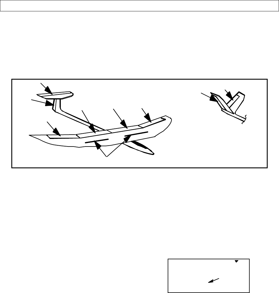
Glider (GLID) Section
– 65 –
Competition Glider Quick Setup Instructions
The following example shows how the Eclipse 7 may be programmed for the “typical” high-
performance six-servo sailplane, shown below. Six servos are used for right and left ailerons,
right and left flaps, elevator, and rudder. If the model happens to have a V-tail, all the functions
are the same, except for the response of the two tail controls. The channel 3 output on the
receiver toggles with the Gear switch and may be used for motor on/off. If you are programming
a model with two wing servos, skip the steps labeled “4WNG only.” Your model’s settings will
be dependent on the setup and linkages. Ask an experienced pilot for assistance setting up.
Right Aileron
Elevator
Rudder Right Flap Left Flap Left Aileron
Spoilers
Right Ruddervator
Left Ruddervator
V-Tail
1. Before you begin, be sure that all of
your aileron and flap servos are plugged into
the proper receiver channels:
CH1 — Right aileron
CH2 — Elevator
CH3 — Motor on/off or spoiler
CH4 — Rudder
CH5 — Left Aileron
CH6 — Right Flap (4WNG only)
CH7 — Left Flap (4WNG only)
2. Enter the SETUP mode by turning on
the transmitter while pressing the two Up
Down Edit buttons simultaneously. You will
be in the model setup (MSEL) menu.
3. Make sure you’re in a clear memory. If
necessary, use the Cursor Right button to
move to a new model memory. The selected
model memory is indicated by the little
flashing arrow pointing down. Power down
if you’ve chosen a new memory, then power
up as in previous step.
4. Press the Up arrow until the word GLID
appears, flashing on and off. If it does,
you’re ready to proceed on to the next step.
If not, press the Left or Right Cursor keys
until it appears. You must press both Data
keys to “Save” the setting; when you do
this, there will be two beeps. This is how
you select the type of model you wish to
use.
WARNING: selecting a different model type
will erase the settings in the model memory.
BE SURE you’re in the correct model
memory before selecting a new model type,
or you might accidentally erase a model
you’re using! (The other memories will not
be affected.)
GLID
421 3 567
MODEL
flashing
5. Now it’s time to select the wing type.
Select 2WNG for models with two aileron
servos, and 4WNG for models with two
ailerons and two flaps. Press the Up arrow
until you see the word “WING” in the upper
right of the display. The wing type in the
lower left will be flashing. You must press
both Data keys to save the wing type.
Glider (GLID) Section
– –
66
4WNG
421 3 567
MODEL
flashing
WING
6. Press the Up arrow once. This gets you
into the model name mode (note that the
words “MODEL” and “NAME” appear in
the upper left of the display).
7. Now you can select four letters to
identify your model. With the first of the
four letters flashing, press the Data +Increase
or –Decrease key to change the letter that is
displayed. Stop when the first letter is the
one you want.
8. Press the Right Cursor key once to get to
the second letter. Repeat the previous step
to choose the second letter.
9. Repeat two more times to fill out the
remaining two letters. If you like, you can
hit the right cursor button one more time and
select a number between 0 and 199 for
further identification. It can be handy to use
this to store the plane’s channel number.
10. Press the Up arrow once. This gets you
into the Timer menu (TIME). If you want,
you can use the Data +Increase or –Decrease
keys to select the amount of time you want
the stopwatch to count down.
11. This completes the initial part of the
setup. Now, we’ll go ahead and customize
the GLID settings for your model. Switch
transmitter power OFF.
12. Turn the transmitter on. When you do,
you will find that channels 1 and 5 act as
ailerons. Channels 6 and 7 will only move
when the flap knob (VR1) is moved.
13. Now check that each servo moves the
proper direction. Move the aileron, elevator,
and rudder sticks. Be sure that the channels
go the proper direction. If not, go to the
Reversing menu (REV) by hitting the Down
arrow. Follow the procedures in the ACRO
setup example, for details.
14. (4WNG only) Move to A →
→ →
→ F by
pressing the Up Down Edit buttons. Activate
it by pressing the Active/Inhibit (Clear) key
(‘On’ or ‘Off’ will be flashing depending on
the position of the Flt condition switch:
forward is on).
A->F
CH 16
SLV
MAS 7
ON
15. (4WNG only) Next, move the aileron
stick and be sure that both flaps move the
same directions as the ailerons. If they do,
move on to the next step. If they don’t,
reverse them in the REV menu. Check
again that the flaps now move with the
ailerons.
A->F + 50
CH
%
16
SLV
MAS 7
ON L/U
16. (4WNG only) Reduce the rate that the
ailerons mix to the flaps by pressing the
Cursor Right key until the percent sign
flashes. You can independently set the up
and down travel for each flap, which is
handy for models which have hinging that
prevents motion in one direction. We
suggest that you set the mixing rate to 50%
on all four settings. You can increase this
later if you find you need more
maneuverability.
17. Now all the servos should function
properly for different stick motions. When
you move the right-hand stick to the right,
the servos on the right wing should move the
controls upwards, and the servos on the left
should move the left wing controls
downward. Rudder and elevator should also
respond properly.
Spend some time getting the correct motions
in this step. If you try to do it later within
Glider (GLID) Section
– 67 –
the different mixing functions, you will get
all messed up!
18. Now we’ll input values for aileron
differential. Press one of the Up Down Edit
buttons to get to ADIF. The function is
already activated, but it's set to 100% on
both sides, zero differential.
19. The display shows little triangles over
and under the numeral 1. This means that
we are programming the aileron stick input
(the upper triangle) into the right aileron
servo, CH1 (triangle under the 1).
ADIF +100
CH
%
15
SLV
MAS
L/U
Normally, we want to have more up aileron
travel than down travel. Hold the aileron
stick to the right but leave the percentage
setting at 100%. Now move the aileron stick
to the left and use the Data –Decrease key to
drop it to 60-70%.
20. Now we’ll repeat the previous step for
the left aileron. Press the Cursor Right key
once, so that the small triangle is under the
number 5. Now we’ll set the differential on
the second aileron. Holding the aileron stick
to the left, we leave the percentage setting at
100%. Now move the aileron stick to the
right and use the Data –Decrease key to drop
it to 70% or so. Now, when you move the
aileron stick, both ailerons will go up more
than down.
ADIF + 70
CH
%
15
SLV
MAS
R/D
21. Move to the full-wing camber control
(F->A) menu, and activate by pressing the
Active/Inhibit (Clear) key. For this function,
we recommend using a setting of 100% so
the motion of all four wing servos is the
same. It is important to have flap and
aileron horns that are the same length, but if
they differ (hopefully in pairs) it is possible
to make some corrections here. The
camber-changing is done by turning the
knob on the top left of the transmitter (VR1
flap knob, on the top left of the transmitter).
The default settings for Flap → Aileron
mixing are such that you get equal motion
above and below the neutral camber
position. There is a neutral point setting
command in this menu, which can be
reached by pressing the Cursor Right key
inside of the F->A menu. However, we
recommend not using this command. It does
move the flap neutral position relative to the
aileron neutral.
Note that the motion dictated by the Camber
knob (VR1 knob) goes into both positive
and negative camber from the neutral point,
unless you set the F →
→ →
→ A offset (see previous
step).
22. Center the camber knob, also known as
the VR1 knob, on the top left of the
transmitter. Be sure to center all of the
trims, and get all of the servo arms to be
near neutral. Use the clevises to get as close
as you can. This way you won't run out of
subtrim authority.
You can make fine adjustments to the
positions of the two outer ailerons using the
aileron trim (AIL.T) function in the
programming menu. Now, you can set the
neutral position of the two inboard flaps
(CH6 and CH7) relative to each other using
the dual flap trim (DFL.T) knob (VR2).
Then use the subtrims (STRM) to set all the
remaining controls the desired neutral
locations.
STRM 5
CH 4213567
Note: you can set the neutrals for the
ailerons and flaps by using the wing beds (if
they’re foam wings) or matching up with the
rest of the wing. Don’t use the fuselage
airfoil as these are often far from parallel
from one side to the other. Set the elevator
incidence per the manufacturer or plans, and
the rudder should be centered.
Glider (GLID) Section
– –
68
23. Set up the crow (also referred to as
“butterfly”) function for precise spot
landings. The ailerons reflex (go up), and
the flaps drop with movement of the throttle
stick. Turn on by locating the CROW menu
with the Up Down Edit keys, then pressing
the Active/Inhibit (Clear) key. The On or Off
display will be flashing, depending on the
Gear switch.
24. First set the CROW function activation
point. Hit the Cursor Left key one time to
get to the offset setting menu. Now move
the throttle stick all the way up. Enter that
position by pressing the Clear Active/Inhibit
key.
SET +127
CH 16
SLV
MAS
ON 2
%
25. Next, set up the throws for the ailerons.
Hit the Cursor Right key two times to get to
the aileron setting menu (a small triangle
appears over the number 1). Use the Data
+Increase or –Decrease keys to input some
percentage of aileron motion. Move the
throttle stick downwards and be sure the
ailerons go UP with crow. If they don’t,
change the sign in front of the setting
number. You'll probably want a fair amount,
but not all, of aileron travel. Start with
about 50%. Be sure not to use full travel, so
you'll have roll authority while on approach
in full crow command. Notice that you set
the throw for both ailerons at the same time:
this is the reason to have identical control
arm lengths and neutral positions.
CROW + 35
CH 16
SLV
MAS
ON 2
%
26. Now you may set up the throw for the
elevator, but it usually doesn't take much,
and too much will be uncontrollable. We
suggest you set this amount backer you've
flown and know how much elevator motion
is needed to trim. Press the Cursor Right key
once to get to the elevator setting menu (a
small triangle appears over the number 2).
Set the desired number with the Data
+Increase or –Decrease keys.
For starters, use zero or very little elevator
compensation until you fly and determine
what is needed: if the model pitches up with
crow, add down elevator compensation and
if it pitches downwards, add some up
compensation. Make only small changes in
compensation because it has a big effect on
trim. Refer to the sailplane trimming chart
for more details.
CROW 0
CH 16
SLV
MAS
ON 2
%
27. (4WNG only) Now set up the throws
for the flaps as desired. Press the Cursor
Right key once to get to the flap setting
menu (a small triangle appears over the
number 6). Set the desired number with the
Data +Increase or –Decrease keys. Move the
throttle stick and be sure the flaps go
DOWN with crow. If they don’t, change the
sign (this may depend on servo orientation).
You'll probably want as much flap motion as
possible — 90° is great if you can get it.
Like the ailerons, you set both flap offsets at
the same time.
CROW +100
CH 16
SLV
MAS
ON 2
%
28. (4WNG only) Then, using Subtrims, fine
tune to get neutral flaps on both sides. Use
EPAs to get 90° flap travel (or the amount
of travel that you’d like) at full crow. It
may be helpful to use long servo arms on the
flap servos to increase their effective throw.
29. (4WNG only) You can use the S.TM1
(launch) preset for high launches. You can
set the two flaps (CH6 and CH7) to drop for
more lift, and trim with elevator (CH2).
Glider (GLID) Section
– 69 –
Increase the up-elevator preset in small
increments until the plane launches as
steeply as you like, or add down elevator if
the model weaves back and forth or is hard
to control (remember to use the rudder stick,
or rudder coupling, during the launch). A
well-trimmed model may actually have some
down elevator mixed in for launching.
S.TM1 -100
CH 16
ON 2
%
7
Remember that to get the S.TM1 function to
turn on, you have to flip the Flt. Mode
switch Back.
30. (4WNG only) You may also set up the
speedmode presets (S.TM2) for high-speed
cruise between thermals. Reflex the entire
trailing edge a very small amount —10% or
even less all the way across is recommended
for starters. The trailing edge should raise
no more than 1/16" (1.5 mm), or you'll gain
more drag than penetration ability. (The
manual I have incorrectly indicates the on
position for the SPEED mixing — it should
be on the top of the switch, as shown
below.)
S.TM2 + 10
CH 16
ON 2
%
7
31. If desired, add aileron-rudder coupling
(A->R) for coordinated turns. This setting is
highly dependent on the model
configuration. Usually only a small amount
of rudder is needed, especially if a large
amount of differential is present, so start out
with 10–15%. Carefully observe the
direction of the fuselage relative to the
thermal turn the model is making. If the
nose points towards the inside of the circle,
the coupling is too high, and if it points
towards the outside of the circle, you need
more coupling. When everything is set
properly, the fuselage will be tangent to the
thermal turn circle (see page 70 for more
details).
A->R 10
R/D %
ON
While you are flying, watch for trim changes
during launch and crow control actions and
set the compensations to cancel them out.
You may wish to refer to the sailplane
trimming chart presented earlier.

Glider (GLID) Section
– –
70
Glider Model Function Descriptions
EPA — End point adjust
See ACRO instructions on page 41.
D/R — Dual Rates
See ACRO instructions on page 42.
EXP — Exponential
See ACRO instructions on page 43.
FLT.C — Flight Conditions
See ACRO instructions on page 44. There are three FLT.C settings available in the
GLID menus. Note that in addition to the FLT.C features described there, you can also use the
STM.1 and STM.2 subtrim offset functions to program different controls move to new positions.
Together, these can be used to set up launch and speed control positions and offsets for
sailplanes. The trim lever for the flap stick controls the neutral position of both flaps if 4WNG is
on.
In the GLID menus with the 4WNG option on, the flight condition menus allow you to
offset the trim positions inputted by the trim levers for channels 1, 2, 4, and 6. The Speed Flap
Trim offset functions allow you to also offset the position of the elevator servo (CH2) and the
dual flap servos (CH6 and CH7). Speed Flap Trim offset functions are described later.
STRM — Subtrim
See ACRO instructions on page 47.
REV — Servo Reversing
See ACRO instructions on page 47.
PMX1 to PMX5 — Programmable Mixing Functions
See ACRO instructions on page 49
ADIF — Aileron Differential
Ailerons are used to roll or bank the glider's wing, but making a roll or turn has a price. A
wing that generates lift also generates a drag component called induced drag, meaning that drag
is induced as a byproduct of the lifting wing. This means that the wing that is lifting more is also
dragging more, and the resulting drag difference causes the fuselage of the model to yaw away
from the desired turn direction, exactly the wrong thing to have happen. This causes even more
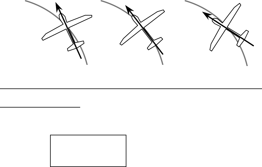
Glider (GLID) Section
– 71 –
drag, which can really hurt a glider's performance. There are two ways to reduce the yaw of the
fuselage, differential (ADIF) and rudder coupling (A->R). Both should be used together, but you
only find ADIF in the glider menus.
Aileron differential causes the ailerons to automatically move with more UP than DOWN
motion, which helps to reduce induced drag. It helps, along with rudder-coupling, to make the
fuselage point straight into the oncoming air stream (this is also called “coordinating the turn”).
The amount of differential is highly dependent on the model configuration. A good
starting point is for the down aileron to move 50% to 75% as much as the up-moving aileron.
Coordinated turn: fuse
lines up with turn direction
(don't change anything!)
Nose points inside circle : too
much coupling or differential.
Reduce one or both.
Nose points outside
circle: increase coupling
and/or differential
Setting Up Differential
1. Press one of the Up Down Edit buttons repeatedly to select the ADIF window. To begin
with, the function is already activated, but it's set to 100% on both sides so there is no
differential. A->R 10
R/D %
ON
2. A small arrow is displayed under the numeral 1, showing that CH1 is the affected channel.
To set the differential for the right aileron (CH1) down travel, hold the aileron stick to the
left side (display shows L/U), and press the Data Decrease key (the right aileron moves down
when left aileron stick is commanded). Continue reducing the percentage until you reach
about 60% to 70%.
3. Make sure that the up travel for the first aileron (CH1) stays at 100% by holding the aileron
stick to the right side (display shows R/D) and verifying that the display shows 100%.
4. Press the Cursor Right key once, to get to the left aileron (CH5) setting menu. A small arrow
is displayed under the numeral 5, showing that CH5 is the affected channel.

Glider (GLID) Section
– –
72
5. Move the aileron stick to the right (display shows R/D), and press the Data Decrease key
reducing the percentage until you reach about 60% to 70%.
6. Make sure that the up travel for the second aileron (CH5) stays at 100% by holding the
aileron stick to the left side (display shows L/U) and verifying that the display shows 100%.
7. If for some reason you want a 0% setting, press the Active/Inhibit (Clear) key. This is the
maximum amount of differential you can get, but will reduce the roll rate if selected.
VTAL — V-Tail Programming
See page 55
E->F — Elevator →
→ →
→ Flap mixing
See ACRO instructions on page 52. The GLID mode E->F function is turned on with
the Flt. Mode switch fully Back. Also, the Elevator-Flap mixing does not provide full trailing-
edge motion on gliders even if the F->A mixing function is activated — only the center flaps are
coupled.
A->R — Aileron →
→ →
→ Rudder mixing
See page 52
F->A — Flap →
→ →
→ Aileron mixing
Flap → Aileron mixing (F->
A) is used to make both ailerons move together as flaps
when the camber-changing/flap knob VR1 is rotated. This allows full-span camber changing on
models with either two ailerons and one flap (2WNG) or two ailerons and two flaps (4WNG). It
is on only if the Ch. 7 switch is forward, and functions at the same time as flap->elevator mixing
(see next menu).
Using Flap->Aileron Mixing
1. Locate the flap->aileron mixing function by scrolling to the F->A menu with the Up Down
Edit keys. The default is for it to be inhibited (Inh). Press the Active/Inhibit (Clear) key so that
the ‘+100%’ display is shown, meaning the ailerons follow the flaps 100%. Depending on the
position of the Ch. 7 switch, either 'On' or 'Off' will be flashing.
2. Press the Cursor Right key once, to get to the percent setting menu. Press the Data +Increase
or –Decrease keys to adjust the amount of mixing to suit.
3. Move the flap knob so the R/D display changes to L/U, or vice versa, and repeat the setting
adjustment for that side of the travel. You can set an input on each side of the flap knob.

Glider (GLID) Section
– 73 –
4. If you want to zero out the amount of mixing on one side of the knob's travel, press the
Active/Inhibit (Clear) key.
5. You can observe the effect of flap->aileron mixing on the aileron servos when the function is
turned on with the Ch. 7 switch, and you move the flap knob (VR1) back and forth.
F->E — Flap →
→ →
→ Elevator mixing
Flap → Elevator mixing (F->E) is used to make the elevator move to maintain trim
when the camber-changing/flap knob VR1 is rotated. It functions at the same time as flap-
>aileron mixing (see previous menu). F->E mixing is on only if the Ch. 7 switch is forward.
Setting Up Flap->Elevator Mixing
1. Get to the flap->elevator mixing function by locating the F->E menu with the Up Down Edit
keys. The default is for it to be inhibited (Inh). Press the Active/Inhibit (Clear) key so that the
‘+100%’ display is shown, meaning the elevator follows the flaps 100%. Depending on the
position of the Ch. 7 switch, either 'On' or 'Off' will be flashing.
2. Press the Cursor Right key once, to get to the percent setting menu. Press the Data +Increase
or –Decrease keys to adjust the amount of mixing to suit. You probably want to select a
number like 10% or less, since the elevator is very powerful as a trimming device.
3. Move the flap knob so the R/D display changes to L/U, or vice versa, and repeat the setting
adjustment for that side of the travel. You can set an input on each side of the flap knob.
4. If you want to zero out the amount of mixing on one side of the knob's travel, press the
Active/Inhibit (Clear) key.
5. You can observe the effect of flap->elevator mixing on the elevator servo when the function
is turned on with the Ch. 7 switch, and you move the flap knob (VR1) back and forth.
CROW — Crow mixing (airbrakes)
The Crow mixing function is useful for increasing the drag of a model during landing
approaches, which makes the approach steeper and slower, making landings shorter and easier.
This is especially useful for sailplanes, where applying down elevator to steepen the glide also
speeds things up and makes landings very difficult. Crow is activated by the flap (throttle) stick
position. Ailerons, elevator, and flaps are the three controls that are commanded by crow
function, which is also called “butterfly” in the sailplane world.
The idea of the crow function is to simultaneously raise the ailerons (which reduces the
wing’s lift), and drop the flaps (to regain the lift lost by the up aileron movement). Elevator
motion may also be also commanded if needed to prevent a trim change induced by the flap and

Glider (GLID) Section
– –
74
aileron motion. Normally, crow is set up so that the maximum control movements (maximum
drag) occur at "low" throttle stick position (towards the bottom of the transmitter). The Gear
switch must be forward for Crow to operate.
Setting Up Crow Mixing
1. Start by locating the CROW menu with the Up Down Edit keys. Either the ON or OFF display
will be flashing, depending on the position of the Gear switch (forward is on).
2. First set the CROW function activation point. Hit the Cursor Left key one time to get to the
SET menu. Now move the throttle stick all the way up. Enter that position by pressing the
Clear Active/Inhibit key. The display should read a number around +125%.
SET +127
CH 16
SLV
MAS
ON 2
%
3. Make sure CROW is ON by moving the Gear switch forward. Verify by looking at the
flashing indicator.
4. Next, set up the throws for the ailerons. Press the Right key two times to get to the aileron
setting menu (a small arrow will appear over the number 1 in the display). Press the Data
+Increase or –Decrease keys to adjust the amount of UP aileron motion. Move the throttle
stick all the way down and be sure the ailerons go UP. If they don’t go up, but go down
instead, press the Clear Active/Inhibit key and then press the other Data key to achieve the
desired up aileron travel (this may depend on servo orientation). You'll probably want a fair
amount, but not all, of aileron travel. Be sure not to use full travel, so you'll have roll
authority while on approach in full crow command. Notice that you set the throw for both
ailerons at the same time: this is the reason to have identical control arm lengths and identical
neutral positions.
CROW + 35
CH 16
SLV
MAS
ON 2
%
5. Now press the Right key to get to the elevator compensation menu (a small arrow will
appear over the number 2 in the display). Press the Data +Increase or –Decrease keys to set up
the throw for the elevator as desired. Move the throttle stick and be sure the elevator goes UP
with crow. If it goes down, press the Clear Active/Inhibit key and then press the other Data key to

Glider (GLID) Section
– 75 –
achieve the desired up elevator travel (this may depend on servo orientation). For starters, use
zero or very little up elevator compensation until you fly and determine what is needed: if the
model pitches up with crow, add down elevator compensation and if it pitches downwards, add
some up compensation. Make only small changes in compensation because it has a big effect on
trim. Refer to the sailplane trimming chart on page 81 for more details.
6. Now press the Right key to get to the flap setting menu (a small arrow will appear over the
number 6 in the display). Press the Data +Increase or –Decrease keys to set up the throws for
the flaps as desired. Move the throttle stick and be sure the flaps go down with crow. If they
don’t go down, but go up instead, press the Clear Active/Inhibit key and then press the other
Data key to achieve the desired down flap travel (this may depend on servo orientation).
You'll probably want as much flap motion as possible — 90° is great if you can get it. Like
the ailerons, you set both flap offsets at the same time.
CROW +100
CH 16
SLV
MAS
ON 2
%
7. If you can't get enough travel, go to the EPA menu and be sure CH6 and CH7 are set as high
as possible to get 90° flap travel. Of course, you can reduce them to get the amount of travel
that you’d like at full crow, but this is better done in the Crow menu as given in the previous
step. It may be helpful to use long servo arms on the flap servos to increase their effective
throw.
Remember to try your crow setup out at higher altitudes to verify that the trim doesn’t
change rapidly. If you want to steepen the descent, increase the flap downward deflection while
increasing the up aileron movement.
Caution: when setting up crow, do not call for too much aileron “up” travel, or you’ll lose
roll authority, and this occurs at a crucial time, when your model is flying relatively slowly on a
landing approach. Always make changes in small increments, don't try to do it “all at once.”
S.TM1, 2 — Speed Flap Trim offsets(Camber mix) 1, 2 (4WNG only)
Speed Flap Trim Offsets, together with flight conditions, are a way to set up gliders with
four wing servos (4WNG). They do not appear in the two wing servo (2WNG) menu. Speed
Flap Trim offsets are used to offset the positions of the elevator servo (CH2) and the inboard
flaps (CH6 and CH7) by flipping the Flt. Mode switch. Together with the Flight Condition

Glider (GLID) Section
– –
76
menus (FLT.C), you can command any position of the inboard flaps, ailerons, and elevator by
flipping the Flt. Mode switch, and without using Speed Flap Trims.
Speed Flap Trim offset #1 is On when the Flt. Mode switch is fully back., and is
commonly used for the "speed" mode, where the trailing edge is reflexed. Speed Flap Trim offset
#2 is On when the Flt. Mode switch is fully forwards, and is commonly used for setting up
offsets needed for good launches.
Setting Up Speed Flap Trim Offsets
1. Start by locating the S.TM1 menu with the Up Down Edit keys, then pressing the Active/Inhibit
(Clear) key. Either the 'Off' or the ‘On’ display will be flashing, depending on the position of
the Flt. Mode switch. Also, the indicators for CH2, CH6, and CH7 will appear at the top of
the display
S.TM1 -100
CH 16
ON 2
%
7
2. First, you'll set the elevator (CH2) function offset amount. Make sure S.TM1 is ON by
moving the Flt. Mode switch fully back. Verify it's on by looking at the flashing On
indicator. Hit the Cursor Right key one time, and a small arrow will appear over the numeral
2.
3. Next, set up the elevator (CH2) motion. Press the Data +Increase or –Decrease keys to adjust
the amount of elevator offset. Use a small amount at first, as the elevator is very effective.
4. Now set up the throws for the CH6 flap. Hit the Cursor Right key one time, and the small
arrow will appear over the numeral 6. Now use the Data +Increase or –Decrease keys to
adjust the amount of CH6 flap offset.
5. Next set up the throws for the CH7 flap. Hit the Cursor Right key once, and the small arrow
will move over the numeral 7. Use the Data +Increase or –Decrease keys to adjust the
amount of CH7 flap offset.
6. Locate the S.TM2 menu by pressing the Up Edit key, and then press the Active/Inhibit (Clear)
key to turn it on. Either the 'Off' or the ‘On’ display will be flashing, depending on the
position of the Flt. Mode switch.
7. Repeat the previous instructions for the second set of inputs for elevator, CH6, and CH7.
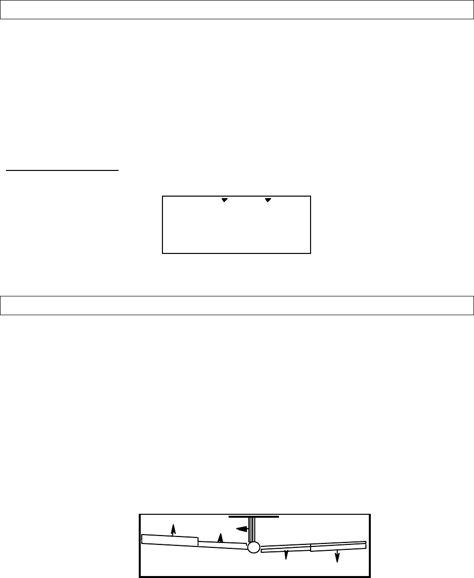
Glider (GLID) Section
– 77 –
AIL.T — Aileron trim
Aileron Trim is a special trimming function for gliders with either two or four wing servos.
It provides a simple way to adjust the position of the outboard wing controls (CH1 and CH5)
without resorting to the Speed Flap Trim menu. When you adjust the Aileron Trim setting, you
move the two outboard wing controls together — they go upwards or downwards together. In
models with four wing servos, you can use Aileron Trim together with the Dual Flap Trim
function (see below) to set any position of the wing controls without using subtrims.
Using Aileron Trim
1. Turn on Dual Aileron Trim by locating the AIL.T menu with the Up Down Edit keys.
AIL.T +64
CH 15
%
2. Adjust the percentage to neutralize them relative to each other with the DATA keys.
A->F — Aileron →
→ →
→ Flap mixing (4WNG only)
To roll a sailplane, we must increase the lift on one wing and reduce lift on the other. The
model will of course roll towards the wing with reduced lift. For minimum drag when turning, we
want to have the way the lifting is done vary smoothly along the span (i.e. zero at the root and
maximum at the tips). Unfortunately, to do this requires a control surface that tapers from zero at
the root to maximum at the tip. Since this is impractical, we mix from the ailerons to the flaps as
shown below, so the inner ailerons don’t move as far as the outer ones. This is an approximation
of the ideal lift for rolling, and will reduce the drag created while banking the wings.
It’s more efficient to use both inboard and outboard wing controls to make a turn. For a
left turn, the left ailerons go up, the right ones go down. The length of the arrows is proportional
to the control movement (notice that inboard ailerons are programmed to move a smaller angle).
Rudder coupling is also shown and may be programmed with the R->A mixing function.
(view from behind)
Aileron->Flap mixing is turned on and off with the Flt. condition switch. You can adjust
the amounts of up and down mixing independently, which is nice if your model's flaps are hinged
on the bottom and they cannot move up past a certain point.

Glider (GLID) Section
– –
78
Using Aileron->Flap Mixing
1. Turn on Aileron->Flap mixing by locating the A->F menu with the Up Down Edit keys. The
default is for it to be inhibited (Inh). Press the Active/Inhibit (Clear) key so that the ‘On’
display is shown.
2. First, you'll set the aileron (CH1)->CH6 function mixing amount. Make sure A->F is On by
moving the Flt. condition switch fully back. Verify it's on by looking at the flashing On
indicator. Hit the Cursor Right key one time, and a small arrow will appear over the numeral
1 and under the numeral 6.
3. To set the UP mix amount for the right flap, hold the aileron stick to the right side (display
shows R/D), and press the Data Decrease key. Continue reducing the percentage until the
servo stops buzzing. If there's no buzzing, you can start with about 50%. If your model has
bottom-hinged flaps, you can get to 0% quickly by pressing the Active/Inhibit (Clear) key.
4. Now set the Down mix amount for the right flap (CH6). Holding the aileron stick to the left
side (display shows L/U), use the Data Decrease key to reduce the percentage to about 50%.
5. Now we'll do the same for the second flap servo (CH7). Press the Cursor Right key once, to
get to the left flap (CH7) setting menu. A small arrow is displayed under the numeral 7,
showing that CH7 is the affected channel. Move the aileron stick to the right (display shows
R/D), and press the Data Decrease key reducing the percentage until you reach about 50%.
6. Set the up mix amount for the second flap (CH7) as you did for the first flap servo. Hold the
aileron stick to the left side (display shows L/U) and press the Data Decrease key to reduce
the percentage to about 50%. Again, if your model has bottom-hinged flaps, you can get to
0% quickly by pressing the Active/Inhibit (Clear) key.
DFL.T — Dual Flap Trim (4WNG only)
Dual Flap Trim is a trimming function for gliders with four wing servos, and does not
appear in the two wing servo (2WNG) menu. It provides a simple way to adjust the position of
the inboard flaps (CH6 and CH7) without resorting to the subtrim menu. When you activate
Dual Flap Trim, you can turn the right-hand knob (VR2) to move the two inboard flaps against
each other — one goes upwards, the other goes downwards. Together with the Flap/Camber
control knob (VR1), you can set any position of the inboard flaps without using subtrims.

Glider (GLID) Section
– 79 –
Using Dual Flap Trim
1. Turn on Dual Flap Trim by locating the DFL.T menu with the Up Down Edit keys. The
default is for it to be on. If you wish to disable the dual flap trim, press the Active/Inhibit
(Clear) key so that the “inh’ display is shown.
DFL.T On
CH 67
2. Turn the VR2 knob one way or the other and observe the response of both inboard flap
servos. Adjust the knob to neutralize them relative to each other. If you inhibit this function,
they'll return to their original positions.

Glider (GLID) Section
– –
80
Sailplane Trimming and Adjusting
The following chart gives procedures that may be followed when trimming a new
sailplane. The flights should be made in near-calm conditions, and repeat them several times
before making adjustments. If any changes are made, go back over the previous steps and verify,
or further adjust as necessary.
One of the most critical steps is the center-of-gravity (CG)/decalage testing (Step 3).
Decalage is a fancy term describing the relative angle difference between the wing and horizontal
tail. Although the control neutrals have been set in Step 1, there are differing combinations of
elevator trim and CG that produce stable flight. In general, by moving the CG back you get
better performance and you reduce the stability, making the model more difficult to fly and
requiring more attention from the pilot. Moving the CG back lessens the download on the
model’s tail, which means the wing and tail are working more together and less against each other
as they do with a forward CG. Many contest flyers use a CG position located between 35 and
40% of the mean wing chord, which is near the back limits for stability (the mean chord is just
about the same as the average chord, which is calculated by dividing the area by the wing span).
How you set you model up really depends on your preferences. A nose-heavy model will be
easier to fly but will lack the performance of the back-CG model.
You should also set differential and/or rudder coupling carefully. Incorrect settings will
result in needless increased drag, and may be checked fairly easily. If you practice keeping the
fuselage straight while gently rocking the wings back and forth, you’ll learn how to coordinate
turns and won’t need coupled rudder any more. You can also learn about the proper amount of
differential or rudder coupling by studying the figures of the model circling in the “coordinating
turns” section, Chapter 5. Too much differential can make the model sluggish when entering or
exiting turns and banks.
Setting up butterfly can be tricky. The reader is referred to the section earlier in this
chapter which describes the instructions contained in the chart’s line 4, 5, and 6. The elevator
delay can be particularly useful to eliminate trim changes with the application of butterfly.
Whatever you do, be sure to spend a lot of time trimming your sailplane. If you have a
nearby slope, practice flying on very light days, where you can just barely keep the model
airborne. It is under these conditions that you learn whether your model is really trimmed
properly.

Glider (GLID) Section
– 81 –
SAILPLANE TRIMMING CHART ©1996-2001 by Don Edberg (all rights reserved)
To test for … Test Procedure Observations Adjustments
1. Model Control Neutrals Fly the model straight
and level Adjust the transmitter trims for
hands-off straight & level flight, no
camber control.
Change electronic subtrims
and/or adjust clevises to center
transmitter trims.
2. Control Throws
Note: be sure all aileron &
flap horn pairs have
matching angles
Fly the model and apply
full deflection of each
control in turn. Camber
control in neutral (setup
6 & 9).
Check the model’s response to
each control input. Set flaps for as
much down flap as possible in
glide path control (90° is good) <5°
reflex needed.
• Aileron & elevator rates: set
for desired authority
• Rudder: set for max. throw
• Set flap motions in Steps 4, 5,
& 9.
3. Decalage & Center of
Gravity (Note: this is an
iterative procedure,
depends on desired
handling characteristics.
Back CG = less stability
but better performance)
Trim for level glide.
Enter 45° dive (across
wind if any) and release
controls. CAUTION:
beware of airspeed &
flutter.
A. Does the model continue its
dive without pulling out or
diving?
B. Does the model start to pull out
(nose up)?
C. Does the model start to tuck
(dive more nose down)?
A. No adjustment
B. Reduce incidence (add
down elevator) and/or
reduce nose weight
C. Increase incidence (add up
elevator) or add nose
weight)
4. Glide Path Control
Settings — Pitch Trim
Note: be sure all aileron
& flap horn pairs have
matching angles.
Fly the model and slowly
apply full deflection of
glide path control
(airbrake stick).
Observe any pitch
changes.
A. Nose drops, up elevator
required for level flight
B. No pitch change
C. Tail drops, down elevator
required to maintain level flight
A. Several options:
1) more up elevator mix;
2) reduce aileron reflex*;
3) increase flap motion*
B. No adjustment
C. Reverse of A
5. Glide Path Control
Settings — Elevator
Delays
Rapidly apply full glide
path, observe initial
pitching response
A. Nose drops
B. No pitch change
C. Nose rises
A. increase elevator delay %
B. No adjustment
C. Reverse of A
6. Glide Path Control
Settings — Roll
Response
Fly the model and apply
full glide path control.
Observe any roll motion.
A. Model rolls to right when glide
path control (airbrake stick)
activated
B. No roll motion
C. Model rolls to left
A. Mix in less right & more left
aileron reflex with airbrake
motion
B. No adjustment
C. Reverse of A
7. Differential/Coupled
Rudder setting Fly the model and apply
alternating left & right
aileron commands.
Observe path of fuselage
line.
A. Model yaws to right with left
aileron and vice versa
B. Fuselage traces straight line
C. Model yaws to left with left
aileron and vice versa
A. Increase differential and/or
amount of rudder coupling
B. No adjustment
C. Reduce differential and/or
amount of rudder coupling
8. Camber (full wing aileron
& flap droop or reflex)
setting
Put the model in a
straight glide passing in
front of you. Apply
camber control.
A. Model slows down & stalls or
sinks rapidly
B. Model slows slightly
C. Model speed unchanged
A. Reduce amount of droop
&/or add elevator
compensation
B. No change needed
C. Reverse of A
9. Launch Settings
(Part 1) Switch to Launch mode.
Launch the model &
observe climb angle and
required control inputs
A. Shallow climb angle; lots of up
elevator required
B. Model climbs steeply with little
control input needed
C. Too steep climb, weaves back
& forth, down elev. required
A. Move towhook rearwards
small amount, increase up
elevator preset a little, or
add camber
B. No adjustment
C. Reverse of A
10. Launch Settings
(Part 2) Switch to Launch mode.
Launch the model &
observe climb angle and
required control inputs
A. Model banks left on tow
B. Model climbs straight ahead
with no roll input needed
C. Model banks right on tow
D. Model tip stalls to one side
A. Reduce left ail & flap droop
or increase right ail / flap
droop
B. No adjustment
C. Reverse of A above
D. Check droop same on both
sides. Increase aileron or
decrease flap droop
11. Speed Settings Switch to speed mode
(entire TE reflexed
slightly, <1/16”/1 mm)
A. Nose drops
B. No pitch change
C. Tail drops
A. Increase up elevator preset
B. No adjustment
C. Reverse of A
12. Elevator-to-Camber
Coupling Setting Fly model at high speed,
bank & pull up A. Model keeps speed and comes
about rapidly
B. Model slows down
A. Increase down flap or leave
alone
B. Reduce amount of down
flap
*Note: Swept wing planform may cause opposite reactions, so experiment until proper behavior is attained.
Helicopter (HELI) Section
– –
82
Eclipse 7 Helicopter (HELI) Programming
This section describes how to use the Eclipse 7
helicopter functions (model type HELI). Descriptions of the
other functions, such as endpoints, dual rates, expo, etc., are
contained in the aircraft (ACRO) section.
The HELI menu provides three flight conditions in
addition to the normal one (NOR). ST1 may be used for
forward flight and mild aerobatics, ST2 may be used for
inverted, and ST3 is used for autorotations.
Helicopter Functions Map......................see right
Helicopter Setup Example...............................84
R->T...........Rudder->Throttle mixing...............89
GYRO...........Gyro Settings .................................90
HOLD...........Throttle Hold .................................90
THCV...........Throttle Curve ...............................91
PTCV...........Pitch Curve....................................91
RVMX...........Revolution mixing..........................92
SWAH...........Swashplate settings (120’, 180’)....94
Hovering Pitch Adjusting knob...........................96
Hovering Throttle Adjusting knob......................96
Helicopter Trimming Chart ............................97
The Eclipse 7 system comes with three choices for the
helicopter’s swashplate arrangement, which may be found in
the setup menu: normal (NOR), 120° (120’), and 180°
(180’). NOR is the standard swashplate where one servo
each performs the collective pitch, elevator, and aileron
functions. 120° and 180° are intended for three-servo
swashplates needing special mixing to get the servos to
properly provide the required pitch, elevator, and aileron
functions.
CH1
CH2
CH1CH6
CH2
NOR 180°
CH2
CH1CH6
120°
CH6
Dual Rate Set [D/R]
End Point Adjust [EPA]
Press both
Edit/Display keys
Revolution [RVMX]
Prog. Mix 2 [PMX2]
Pitch Curve [PTCV]
Rud → Thr Mix [R-T]
Prog. Mix 1 [PMX1]
Gyro setting [GYRO]
Exponential [EXP]
Sub-Trims [STM]
Servo Reversing [REV]
Throttle Cut [T.CUT]
Throttle Curve [THCV]
Throttle Hold [HOLD]
Swashplate [SWAH]
120’, 180’ only
Normal Display Mode
Voltage/Timer Display

Helicopter (HELI) Section
– 83 –
Eclipse 7 Helicopter Controls and Switch Assignments
This should be the “Eclipse 7 Mode 2 Switch Configuration List”
drawing with only the HELI features listed (less confusing).
This figure shows the assignments for a Mode 2 system as supplied by the factory for North
America. Note that some of the functions will not operate until activated in the mixing menus.
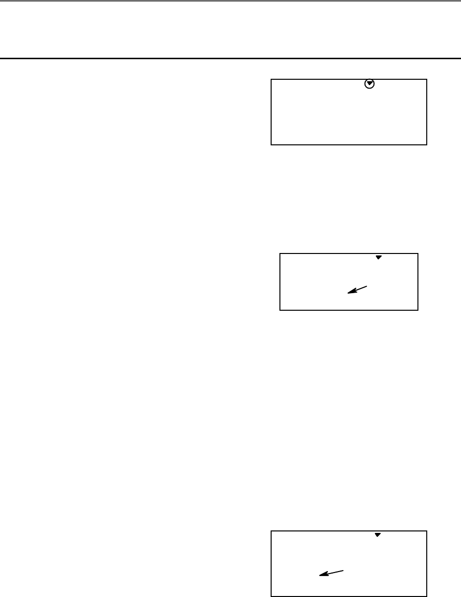
Helicopter (HELI) Section
– –
84
Helicopter Setup Instructions
The following example shows how the Eclipse 7 may be programmed for a helicopter model.
Your model’s settings will be dependent on the setup and linkages. If you’re not sure about the
settings for your particular model, please ask an experienced pilot for assistance.
The helicopter setup procedure presented
below uses a standard helicopter setup, one
servo each for ailerons and elevator. You can
use a similar procedure to set up your own
model; your setting’s numbers and
percentages will probably be different.
1. In the helicopter, install each servo and
hook up the aileron, elevator, throttle, rudder,
and pitch pushrods to the servos in accordance
with the model’s instructions or plans.
Be sure that all of your servos are plugged into
the proper receiver channels:
CH1 — Aileron
CH2 — Elevator
CH3 — Throttle
CH4 — Rudder
CH5 — Gyro
CH6 — Pitch
CH7 — Aux. or heading hold control
If your model uses 120° or 180° swash
programming, plug in the servos as indicated
in the table on page 18.
We recommend that you do this programming
exercise with the servos installed in the model
and connected to the respective control
surfaces. This will enable you to immediately
see the effect of each programming step.
2. Model Memory. Turn on your transmitter
while holding the two Edit Display keys. This
gets you into the model select (M.SEL) menu.
Press the Cursor Right button to move to a
new model memory. The model number of
the model memory you select is indicated by
the little arrow pointing down. The figure
shows Memory #4.
M.SEL
4213567
MODEL
3. Model Type. Press the UP arrow two
times. The word ACRO will appear, flashing
on and off. Press the Left or Right Cursor keys
until HELI appears. You must press both
Data keys to “Save” the setting. This is how
you select the type of model you wish to use,
either ACRO, HELI, or GLID.
HELI
421 3 567
MODEL
flashing
WARNING: selecting a different model type
will erase the settings in the model memory.
BE SURE you’re in the correct model memory
before selecting a new model type, or you
might accidentally erase a model you’re using.
4. Swash Type. Now it’s time to select
the swash type. Select NOR for helis with
independent aileron, elevator, and pitch
servos; 120’ for models using 120°
swashplates; and 180’ for models with 180°
swashes. Press the Up arrow until you see the
word “SWASH” in the upper right of the
display. The swash type in the lower left will
be flashing. You must press both Data keys to
save the swash type.
NOR
4213567
MODEL SWASH
flashing
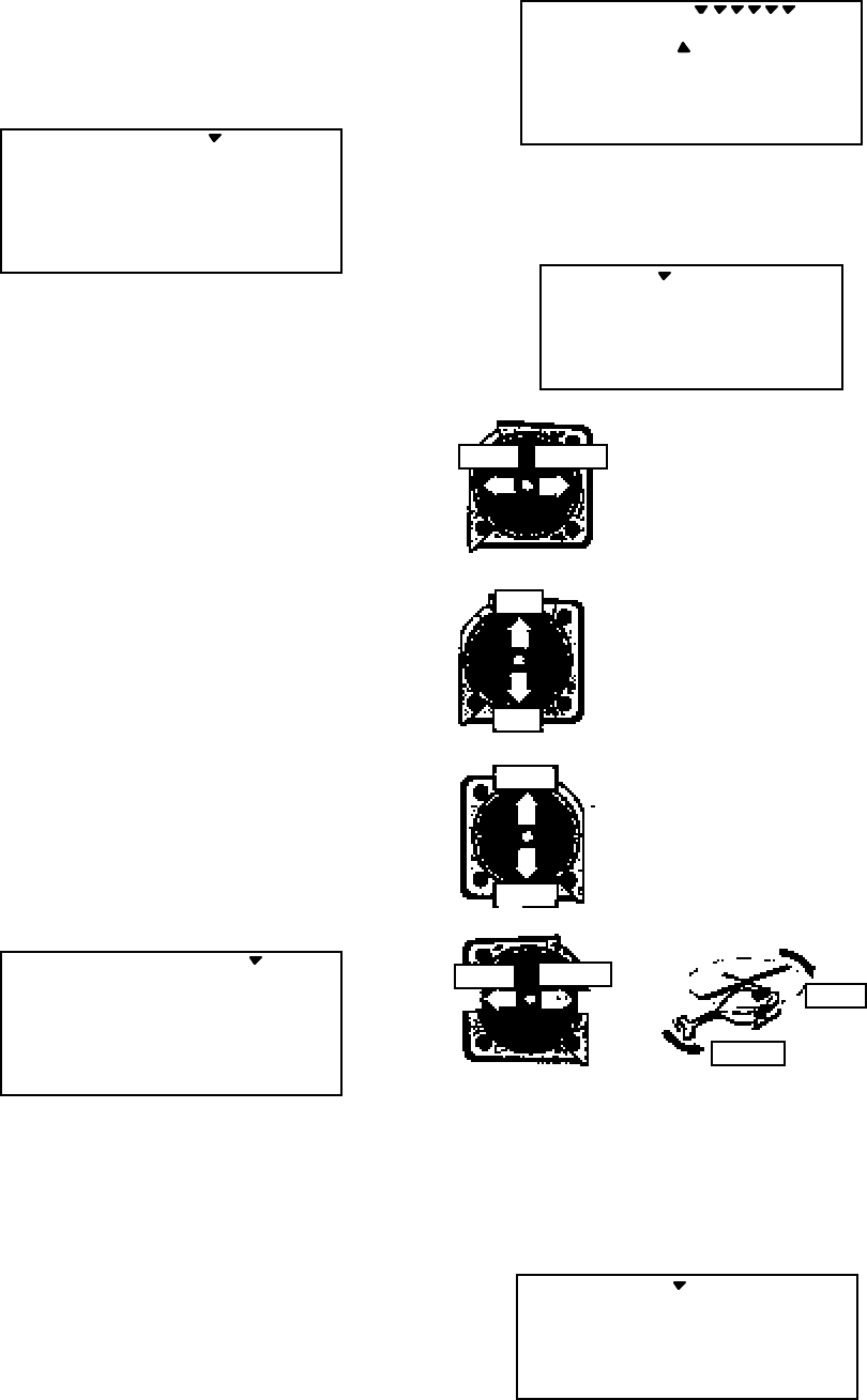
Helicopter (HELI) Section
– 85 –
5. Name your model. Press the UP arrow
once. This gets you into the model name
mode (note the words MODEL and NAME in
the upper left of the display).
****- 0
421 3 567
MODEL
6. Now you can select four letters to identify
your model. With the first of the four letters
flashing, press the Data +Increase or –
Decrease keys to change the letter that is
displayed. Stop when the first letter is the one
you want.
7. Press the Right Cursor key once to get to
the second letter. Repeat Step 5 to choose the
second letter.
8. Repeat the previous steps two more times
to fill out the remaining two letters. If you
like, you can hit the right cursor button one
more time and select a number between 0 and
199 for further identification.
9. Set the stopwatch. Press the UP arrow
once. This gets you into the Timer menu
(TIME). Use the Data Increase and Decrease
keys to select the amount of time you want the
stopwatch to count down. This is handy to
keep track of engine running time so you don't
run out of gas.
TIME 10
421 3 567
MODEL
10. This completes the initial part of the setup.
Now, we’ll go ahead and customize the
settings for your model. Switch transmitter
power OFF.
11. Servo Directions. Switch transmitter
power back on and check the proper direction
of throw for each servo. Use the reversing
function [REV] to reverse channels as
necessary to get proper throw directions.
REV
CH 4213567
N
R
12. If you’re using 120’ or 180’ swash types,
please use the swashplate (SWAH) menu,
page 94, to adjust these responses.
SWAH + 70
CH 162
%
LEFT RIGHT
Right Aileron: swashplate
tilted towards the chopper's
right side.
Left Aileron: swashplate
tilted towards the left side.
DOWN
UP
Down Elevator: swashplate
tilted towards the chopper's
front.
Up Elevator: swashplate
tilted towards the rear.
HIGH
LOW
HIGH Position: high rotor
pitch AND carburetor fully
opened
LOW Position: low rotor
pitch, carburetor at idle (use
trim tab to fully close)
LEFT RIGHT LEFT
RIGHT
13. Servo Neutrals. First, be sure the hovering
pitch and hovering throttle knobs are centered.
Set up all linkages so that all servos are as
close to mechanical neutral as possible. Then,
use the Subtrim (STRM) window to make fine
adjustments on the servo neutrals.
STRM 5
CH 421 3 567
Helicopter (HELI) Section
– –
86
14. Servo Travel. Use the EPA command to
limit servo travels to prevent binding.
EPA 100
CH 421 3 567L/U %
15. Collective Pitch. The collective pitch
angle (controlled by CH6 on a conventional
helicopter) should vary from -2° to +10° with
full stick motion, depending on the flight
condition. We recommend setting the hovering
pitch (pitch with throttle stick at center) to
+4.5°. Adjust servo arms and EPA values to
get the desired travel at the end points,
measuring with a pitch meter.
16. Engine travel. On the regular display
menu, enter a value of –25% for throttle trim.
Use the EPA menu to set up the carburetor
pushrod so that at full throttle there is no
binding, and so the engine idles smoothly at
low throttle.
17. Throttle Cut. Enter the throttle cut
(T.CUT) menu and enter a value of –25% or
so. Press the Cut button and be sure that the
carburetor fully closes, which will shut off the
engine. Don’t pick too large a number, or
binding may occur.
T.CUT - 59%
3
18. Throttle Curve. You can use the
Throttle Curve (THCV) menu's five-point
setting curves to fine-tune the engine servo's
response. Adjust the throttle position for hover
to get the desired head RPM. You can change
the curve values to make a steeper curve near
idle and shallower curve past hover. See the
THCV menu description on page 91 for more
details.
THCV 0 %
ST1
42135
ST2 NOR
If your instructions don’t give any
suggested values, you may start with the
following settings:
Throttle Curve NOR
Point 1 (low) 2 3 4 5 (high)
% 0 26 45 72 100
19. Pitch Curve. You can use the Pitch
Curve (PTCV) menu's five-point setting
curves to make finer adjustments to the
endpoints and the middle of travel of the pitch
servo.
PTCV 0%
ST1
42135
ST2 NOR
Your model’s instructions may provide
suggested values for the blade pitch angles. If
not, you may want to start with the following:
Pitch Curve NOR
Point 1 (low) 2 3 4 5 (high)
Pitch 0 deg. +5 +6.5 +8.0 +10.0
Backer you’ve set the pitch at each of the five
points, be sure to check that both aileron and
elevator motions do not cause binding at
extreme pitch settings. If they do, use EPA to
reduce travels.
20. Revolution mixing (
RVMX) uses the tail
rotor to suppress the torque reaction of the
main rotor due to changes in collective pitch.
It is disabled whenever Idle-Up or Throttle
Hold are activated.
RVMX may be set on either side of the stick
(note the letters R/D and L/U displayed).
Adjust RVMX mixing for both travel directions
as described in the trimming instructions on
page 97.
Helicopter (HELI) Section
– 87 –
RVMX + 10 %
ST1 ST2 NOR
L/U
21. Gyro settings. You can select an
independent value of gyro gain for each flight
condition by using the GYRO menu. Select
the desired flight condition, then use the Data
keys to choose the desired value. The gyro
must be plugged into CH6. This function will
only work with dual rate heading hold gyros.
GYRO 0%
ST1 ST2 NORST3
22. Aerobatic Setups and Flight Conditions.
Your Eclipse 7 system has three built-in flight
condition menus in addition to the normal
(NOR) hovering mode. Two -- ST1 and ST2 -
- are typically used for aerobatics, including
540° stall turns, looping, and rolling stall turns.
ST3 is used for "throttle hold" so that the
throttle servo is disengaged during
autorotations. These functions are switched
on as follows:
• NOR: ON when Flt. Mode Switch is back.
• ST1: ON, when Flt. Mode Switch centered
• ST2: ON when Flt. Mode Switch is forward.
• ST3: ON when Flt. Cond Switch is forward.
As these functions are switched on or off, ST3
will override all the others, followed by ST2
and ST1, which will override NOR. Regular
settings (NOR) occur when the others are off.
Dual rates, exponentials, throttle and pitch
curves, revolution mixing, and gyro gain may
be independently selected for each condition.
Here are some suggested starting settings if
your instructions do not provide any:
Throttle Curve ST1
Point 1 (low) 2 3 4 5 (high)
% 50 385075 100
Throttle Curve ST2
Point 1 (low) 2 3 4 5 (high)
% 100 50 38 50 100
Pitch Curve ST1
Point 1 (low) 2 3 4 5 (high)
Pitch -4 deg. +0.5 +6.0 +7.5 +9.0
Pitch Curve ST2
Point 1 (low) 2 3 4 5 (high)
Pitch -9 deg. -6.0 0 6.0 9 or 10.0
Pitch Curve ST3 (HOLD)
Point 1 (low) 2 3 4 5 (high)
Pitch -4 deg. -- +6.5 -- +12
23. Throttle Hold Setting. Throttle hold
(HOLD) commands the throttle to a preset
position near idle and disconnects it from pitch
when activated. Move to the HOLD menu and
move the Flt. Cond. switch forward position.
Set the hold position to maintain engine speed
safely above idle without engaging the main
rotor clutch.
HOLD + 10
%
ON
24. Dual Rate Settings. If you find that your
aileron and elevator controls are too sensitive,
you may set dual rates to reduce them. Use
the dual rate (D/R) window to adjust them to
the desired amount of response when the
switch is flipped.
D/R 80
CH
%
ST1
421
ST2 ST3 NOR
This is only a brief introduction to the
setup procedure for helicopters. Be sure to
browse through the pages following this
example to see the details about the menus for
helicopters.
Helicopter (HELI) Section
– –
88
Menu Descriptions — Helicopter
Flight Conditions
Your Eclipse 7 system's HELI menu provides three flight conditions in addition to the
normal one (NOR). Within each condition, you may program an independent set of dual rates,
exponentials, throttle and pitch curves, revolution mixing, and gyro gain. In the HELI menus,
these are automatically called up whenever you switch to a new condition. (In ACRO and
GLID, you have to activate them manually.)
NOR is intended for hovering flight. ST1 may be used for forward flight and mild
aerobatics, ST2 may be used for inverted, and ST3 is used for autorotations as it includes a
throttle hold feature which disengages the throttle servo from collective commands. These
conditions are activated whenever the model memory is chosen to be HELI type.
These flight conditions are switched on as follows:
• NOR: ON when Flt. Mode Switch is back.
• ST1: ON, when Flt. Mode Switch centered
• ST2: ON when Flt. Mode Switch is forward.
• ST3: ON when Flt. Cond Switch is forward.
As these functions are switched on or off, ST3 = HOLD has highest priority, followed by
ST2 and ST1. Regular settings (NOR) occur when all of the others are off. You can see which
condition your transmitter is currently in by viewing the display. The current condition may be
found flashing in the lower right of the TRIM display.
TRIM 0
CH
%
ST1
3214
ST2 ST3 NOR
EPA — End point adjust
See ACRO instructions on page 41.
D/R — Dual Rates
Refer to ACRO instructions on page 42.
EXP — Exponential
See the ACRO instructions on page 43.
STRM — Subtrim
Refer to the ACRO instructions on page 47.
Helicopter (HELI) Section
– 89 –
REV — Servo Reverse
See ACRO instructions on page 47.
T.CUT — Throttle Cut
Described in the ACRO instructions on page 48.
PMX1, PMX2 — Programmable Mixing
See ACRO instructions on page 49. There are two programmable mixers in the helicopter menus.
PMIX-1 is operated with the Rudder D/R switch and PMIX-2 is selected with the Gear switch.
R->T — Rudder →
→ →
→ Throttle Mixing
Rudder → Throttle (R->T) mixing is used to maintain rotor speed so that altitude is kept
constant when the rudder stick is operated in hover. The reason for this mixing is that when
rudder is commanded, the tail rotor consumes a little more power, which reduces the power at
the main rotor and the helicopter drops or climbs. For helicopters with normal rotor rotation,
commanding right rudder (which requires more power) should also increase throttle slightly,
while using left rudder (requires less power) should decrease the throttle slightly. R->T mixing is
handy for hovering but may also be used in 540° stall turns, hovering eights, nose-in circles, Top
Hats, Pirouettes, and other aerobatics.
Setting Up Rudder->Throttle Mixing
1. Press one of the Up Down Edit buttons repeatedly to select the R->T window. The function is
activated by switching the Flt. Mode switch all the way back. It's set to 0% on both sides so
there is no differential.
R->T + 10%
L/U
2. To set the mixing amount for the left rudder, hold the rudder stick to the left side (display
shows L/U), and press the Data Decrease key. Continue reducing the percentage until you
reach about 10%. If for some reason you want a 0% setting, press the Active/Inhibit (Clear)
key.
3. Input the mixing amount for right rudder by moving the rudder stick to the right (display
shows R/D), and press the Data Increase or Decrease key to reach about 10%.
4. Note that R->T mixing may only be set up in the NOR menu.

Helicopter (HELI) Section
– –
90
GYRO — Gyro settings
Gyro settings are used to automatically control the gyro's gain in different flight modes.
It may be set to different values in NOR, ST1, ST2, and ST3 flight modes, allowing you to pick
the gain you need for each circumstance. The Gyro settings control the output at receiver CH7.
Note: this function only works with dual rate heading hold gyros.
Using Gyro Settings
1. Press one of the Up Down Edit buttons repeatedly to get to the GYRO menu. To begin with,
the function is already activated, but it's set to 50% in all four flight modes.
GYRO 0%
ST1 ST2 NORST3
2. To set the mixing amount for the normal (NOR) flight condition, flip the Flt. Mode switch all
the way back. NOR will be flashing on and off. Set the percentage to yield the desired gyro
gain (this is usually a high-gain setting). If for some reason you want a 0% setting, press the
Active/Inhibit (Clear) key.
3. Flip the Flt. Mode switch to its center position. ST1 will be flashing on and off. Set the
percentage to yield the desired gyro gain in this flight condition (this will usually be a lower-
gain setting for reduced damping in stunts).
4. Flip the Flt. Mode switch all the way forward. ST2 will be flashing on and off. Set the
percentage to yield the desired gyro gain.
5. Now flip the Flt. Cond. switch fully forward. You may now input a setting for ST3.
6. Make some test flights to try these settings out. Take note of when more gain is need, and
when less gain is needed. You can adjust all of the gyro settings in each flight condition to
suit your machine.
HOLD — Throttle Hold
The Throttle Hold function moves the engine throttle servo to a selected position near
idle, and disengages it from the throttle stick. It is commonly used during autorotation, and
activated with the Flt. Cond. switch on the right rear of the transmitter. You can set the throttle
position to be held over a -50 to +50% range centered about the throttle idle position. Activating
throttle hold also disables revolution mixing (RVMX).
Helicopter (HELI) Section
– 91 –
Setting Up Throttle Hold
1. Press one of the Up Down Edit buttons until the H0LD window appears. The default is for the
function to be inhibited. To activate the throttle hold function, press the Data –Decrease key.
This will cause the Inh display to change to a -4% value with an ON or OFF display,
depending on the Flt. Cond. switch’s position.
2. Now you can adjust the throttle hold position with the Data +Increase or –Decrease keys,
anywhere between -50 and +50%. (To inhibit this feature, press the Active/Inhibit (Clear) key.)
HOLD + 10
%
ON
3. Check that your throttle goes to the desired hold position by flipping the Flt. Cond. switch
one way and the other. Adjust the number as needed. Be sure to choose an engine speed
that's fast enough to keep the engine from accidentally quitting but slow enough to not engage
the main rotor clutch.
THCV — Throttle Curve
The throttle & pitch curves are tied to the position of the
collective stick, and are specified at five points labeled 1 through
5 below. These “curves” are really straight lines connecting the
settings at the five points, and are defined by assigning servo
movement percentages to five positions of the left stick: lowest =
Point 1, the 1/4-up stick position = Point 2, half-stick = Point 3,
3/4 position = Point 4, and top position = Point 5. With the
numbers as input as shown, the servo would move 50% of full
travel to one side at low collective stick position, and 50% of full
travel to the other side at high stick position.
Example Five-point Curve 100%
75%
50%
25%
0%
LOW ←
←←
← Collective Stick →
→→
→ HIGH
←
← ←
← Servo Response →
→→
→
12345
Curve Point
63%
50%
38%
25%
75%
You can get a linear response by making the five settings
line up as shown above. But if you want another shape, you’re
free to do it. You can “flatten out” or "soften" the curve around
hover as shown here. This is handy for making the control less
sensitive around hover.
5-Pt Curve Soft Near Hover100%
75%
50%
25%
0%
LOW ←
←←
← Collective Stick →
→→
→ HIGH
←
← ←
← Servo Response
→
→→
→
12345
Curve Point
60%
50%
40%
25%
75%
Shallower
slope in this
region
Setting Up The Throttle Curve
1. Press one of the Up Down Edit buttons until the THCV window appears. The default is for a
linear curve, a straight line from 0 to 100% passing through 50% at hover (center, point 3).
Helicopter (HELI) Section
– –
92
2. Be sure you're in the desired flight condition by moving the Flt. Mode and Flt. Cond
switches to their proper position. Remember, you can input separate, independent throttle
curve settings for each flight condition (except for ST3, throttle hold)! Also, be sure to
center the hovering throttle knob
3. You begin at set point #1, idle. A small arrow should appear over the number 1 in the
display, and a value of 0% should be shown. Press the Data +Increase or –Decrease key to
change the setting to your desired value.
THCV 0 %
ST1
42135
ST2 NOR
4. When you're finished with Point 1, move to the next point with the Cursor Right key. A small
arrow over the number 2 indicates you are setting the value for Point 2. Note that the
function is inhibited (Inh) to start with. If you leave it, you get a straight line from points 1 to
3. Otherwise, you can change this setting with the Data +Increase or –Decrease keys. You
can inhibit THCV point 2 or 4 by pressing the clear key.
THCV Inh %
ST1
42135
ST2 NOR
5. Repeat this procedure for Points 3, 4, and 5 by pressing the Cursor Right key, then adjusting
as desired with the Data +Increase or –Decrease keys.
6. When you've completed the settings for the first flight condition (NOR), test fly your model.
When you're satisfied with the settings, use them as a basis for the other flight conditions.
Flip the switches as necessary to get into the new conditions, verify on the display that you
are in the desired flight condition, then set all the five points in by going through the steps
given previously.
PTCV — Pitch Curve
Like the throttle curve described above, pitch curves are tied to the position of the
collective stick, and are specified at five points labeled 1 through 5 below. Setup instructions are
the same as those for throttle curve, except that you may also input a curve for the throttle
hold/ST3 flight condition.
You can get a linear response by making the five settings line up as shown above. But if
you want another shape, you’re free to do it. You can “flatten out” or "soften" the curve around
hover, which is handy for making the control less sensitive there.
Helicopter (HELI) Section
– 93 –
Inputting The Pitch Curve Values
1. Press one of the Up Down Edit buttons until the PTCV window appears. The default is for a
linear curve, a straight line from 0 to 100% passing through 50% at hover (center).
2. Be sure you're in the desired flight condition by moving the Flt. Mode and Flt. Cond
switches to their proper position. Remember, you can input separate, independent throttle
curve settings for each flight condition!
3. You begin at set point #1, idle. A small arrow should appear over the number 1 in the
display, and a value of 0% should be shown. Press the Data +Increase or –Decrease key to
change the setting to your desired value.
PTCV 0%
ST1
42135
ST2 NORST3
4. When you're finished with Point 1, move to the next point with the Cursor Right key. A
small arrow over the number 2 indicates you are setting the value for Point 2. Note that the
function is inhibited (Inh) to start with. If you leave it, you get a straight line from points 1 to
3. Otherwise, you can change this setting with the Data +Increase or –Decrease keys. You
can inhibit THCV point 2 and 4 by pressing the clear key.
PTCV Inh%
ST1
42135
ST2 NORST3
5. Repeat this procedure for Points 3, 4, and 5 by pressing the Cursor Right key, then adjusting
as desired with the Data +Increase or –Decrease keys.
6. When you've completed the settings for the first flight condition (NOR), test fly your model.
When you're satisfied with the settings, use them as a basis for the other flight conditions.
Flip the switches as necessary to get into the new conditions, verify on the display that you
are in the desired flight condition, then set all the five points in by going through the steps
given previously.
RVMX — Revolution mixing
The revolution mixing function mixes pitch commands into rudder (pitch → rudder) in
order to suppress the torque generated by changes in the main rotor’s pitch angle and rotational
speed. You can input independent values for revolution mixing above and below one-half
throttle for each of the NOR, ST1, and ST2 flight conditions. Revolution mixing is disabled
whenever throttle hold (ST3, operated by the Flt. Cond. switch) is on.
For a clockwise-turning rotor, revolution mixing should apply right rudder when pitch is
increased; for a counterclockwise-turning rotor, the opposite should occur. Remember to set the
value for both the top and bottom of the throttle stick's motion.
Helicopter (HELI) Section
– –
94
Note: A procedure for adjusting revolution mixing is given in a table on page 97.
Revolution Mixing Programming
1. Call up the revolution mixing screen by repeatedly pressing one of the Up Down Edit buttons
until the RVMX window appears. The function is active with 0% mixing turned on. Put the
throttle stick to its idle position.
RVMX 0 %
ST1 ST2 NOR
L/U
2. Now press the Data +Increase key. This will increase the percentage of RVMX mixing for
the low side of throttle. You may set a value of 0% to 100% for this side. If you wish to
return the mixing percentage to the default 0% value, press the Active/Inhibit (Clear) key.
3. Move the throttle stick to a position above half-throttle, and change the percentage number to
suit.
4. Now verify that the rudder responds both the correct direction and amount for travel on both
sides when throttle is commanded.
5. Set up the RVMX values for the other flight conditions (ST1, ST2) by flipping the Flt. Mode
switch and repeating these procedures.
SWAH — Swashplate adjust (120’, 180’ only)
The swashplate menu is intended only for helicopters whose collective pitch is
controlled by more than a single servo at a time, and is sometimes referred to as CCPM
(Collective & Cyclic Pitch Mixing). The Eclipse 7 contains settings for 120' and 180'
swashplates. Consult your model's setup instructions to find out which you need.
When you move the collective stick, all swashplate servos should move in the same
direction and the same amount to lift or drop the swashplate without tilting. If the swashplate
should tilt to one side when you command collective, one or more servos is moving the wrong
direction or the wrong amount, and must be adjusted in the SWAH menu. If the swashplate
moves down when pitch should be increasing or vice versa, change the sign in front of all three
servos from (+) to (–) or vice versa. For reference, there is no SWAH menu in the NOR menu,
but the other two swash types do contain the SWAH menu. The swash default settings are
shown below.
NOR 120' 180'
No SWAH menu CH1 +70%, CH2 +70%, CH6 +70% CH1 +70%, CH6 +70%

Helicopter (HELI) Section
– 95 –
Swashplate Programming
1. Consult your model's setup instructions. If two or three servos are needed to move the
swashplate, go to the model setup instructions (page 26) and select the appropriate swash
type.
2. With all the servos hooked up, and the transmitter and receiver turned on, move the
throttle/collective stick up and down. The swash should move up and down with no
rotations. Move the aileron stick left and right. The swash should tilt left and right without
pitching or rising. Move the elevator stick. The swash should tilt fore and back with no
rotations. If there are rotations when collective is moved, or the swash moves up and down
with aileron or elevator, you need to adjust the settings in the swash menu.
3. If the servos do not all respond in the same direction for collective or opposite directions for
aileron and elevator, you will need to reverse one or more of them in the reversing menu
(REV). It may take a little trial and error trying different combinations of normal and reverse
rotation to get the servos to respond properly. Don't worry about the direction they respond,
just that they all move the same for collective and tilt for aileron and elevator.
4. Call up the swash screen by repeatedly pressing one of the Up Down Edit buttons until the
SWAH window appears. The function is automatically active when you select 120' or 180'
mixing in the model setup menu.
SWAH + 70
CH 162
%
5. If all the servos raise the swash with increasing collective, go to the next step. If they lower
the swash, press the Cursor Right key twice to get to the collective setting menu (the arrow
appears over the number 6). Now press the Data –Decrease key until the sign is reversed in
front of the percentage value. Now the swash should properly respond to collective. If
you've done the wrong thing, you can reset the percentage by pressing the Active/Inhibit
(Clear) key.
6. If all the servos tilt the swash to the right with right aileron stick, go to the next step. If they
tilt the swash to the left, press the Cursor Right key once to get to the aileron setting menu
(the arrow appears over the number 1). Reverse the sign in front of the percentage with the
Data –Decrease key. Now the swash should properly respond to aileron.
7. If all the servos tilt the swash back with up elevator stick, go to the next step. If they tilt the
swash forwards, press the Cursor Right key once to get to the elevator setting menu (the
arrow appears over the number 2). Now press the Data –Decrease key until the sign is
reversed in front of the percentage value. Now the swash should properly respond to
elevator. Double check that all three functions, collective, aileron, and elevator, produce the
desired result on the swashplate.
Helicopter (HELI) Section
– –
96
Hovering Throttle Adjustment Knob
The Hovering Throttle knob may be used to "tweak"
the throttle servo's position around hover without
affecting main rotor pitch. It’s handy to make up for
changes in rotor speed caused by variations in
temperature, humidity, or other conditions. To change
the hovering throttle setting, simply turn the Hovering
throttle knob VR1. As shown in the figure, turning the
knob has the largest effect in the hovering region and
leaves the endpoints alone. Please center this knob
before you set neutrals or input throttle curves.
Throttle Stick Motion
Throttle
Servo Response
Changing the
HV-T value
moves the
throttle response
above or below
the straight line
Low High
Idle
Full
Pwr
Hover
Hovering Pitch Adjustment Knob
The Hovering Pitch knob may be used to trim the
collective pitch near hover without affecting throttle.
Like hovering throttle, it’s handy to make up for
changes in rotor speed caused by variations in
temperature, humidity, or other conditions. You can
adjust the hovering pitch value simply by turning the
Hovering pitch knob VR2. Like hovering throttle, this
knob only works near hover and tapers off at either end
of throttle. Please center this knob before you set
neutrals or input throttle curves.
Throttle Stick Motion
Collective Pitch
Servo Response
Changing the
Hovering Pitch
value moves the
pitch response
above or below
the straight line
Low High
Min
Pitch
Max
Pitch
Hover

Helicopter (HELI) Section
– 97 –
Helicopter Flight Trimming Chart
This procedure assumes helicopter is trimmed for hovering. Trimming must be done in
near-calm conditions. Repeat tests several times before making adjustments. If any changes are
made, go back over the previous steps and verify, or further adjust as necessary.
To test … Test Procedure Observations Adjustments
1. RVMX mixing
— Up settings
(Part 1)
Fly the model straight
and level into the wind
at 100 ft altitude, lower
pitch to 0°
Observe rotation as helicopter
descends
A. No rotation
B. Model rotates
counterclockwise
C. Model rotates clockwise
A. None
B. Add right rudder trim
C. Add left rudder trim
2. RVMX mixing
— Up settings
(Part 2)
Bring the helicopter into
hover, add full pitch and
ascend 75 ft
Observe rotation as helicopter
ascends
A. No rotation
B. Model rotates
counterclockwise
C. Model rotates clockwise
A. None
B. Increase UP RVMX mix
C. Decrease UP RVMX mix
3. RVMX Down
mixing settings Begin Down RVMX
mixing with same
number as UP mix.
From inverted flight
(top of loop, or mid-
point of roll, or inverted
part of split-S), add full
negative pitch
Observe rotation as helicopter
ascends
A. No rotation
B. Model rotates clockwise
C. Model rotates
counterclockwise
A. No adjustment
B. Increase Down RVMX
mix
C. Decrease Down RVMX
mix
Adjusting Hovering Pitch and Hovering Throttle
RPM Stick Primary Corrective Action
High Below 1/2 Decrease hovering throttle
Low Below 1/2 Decrease hovering pitch
Perfect Below 1/2 Decrease hovering throttle, decrease hovering pitch
High 1/2 stick Increase hovering pitch, decrease hovering throttle
Low 1/2 stick Decrease hovering pitch, increase hovering throttle
Perfect 1/2 stick Don’t touch a thing!
High Above 1/2 Increase hovering pitch
Low Above 1/2 Increase hovering throttle
Perfect Above 1/2 Increase hovering pitch, increase hovering throttle
Want more Keep 1/2 Decrease hovering pitch, then increase hovering throttle
Want less Keep 1/2 Increase hovering pitch, then decrease hovering throttle

– –
98
GLOSSARY
The abbreviations used with the Eclipse 7 are defined below alphabetically. Related pages are
given in parenthesis following the definition.
A
ACRO .... Acrobatic aircraft menu (1)
ADIF .... Aileron differential. Makes aileron move
more to one side than the other (70)
AIL.T .. Dual aileron trim (75)
ATL ...... Adjustable Travel Limit. Limits throttle
trims to only the throttle idle position.
(built in to your system)
A->F .... Aileron → Flap mixing (77)
A->R .... Aileron → Rudder mixing (52)
C
camber A function which droops or raises the
entire trailing edge of a glider wing.
COPY .... Data copy: command used to copy one
memory to another (24)
CROW .... Airbrake function for gliders
CURSOR Button used to step through menus (18)
D
D/R ...... Dual rate: switch-controlled function
reduces control travels. (42)
DATA..... Editing keys change numbers (18)
DFL.T .. Dual Flap trim knob (77)
E
ELVN .... Elevon function combines ailerons &
elevators for tailless models. (54)
EPA ...... End Point Adjust. Function that adjusts
the servo travel at the left and right
sides. (54)
EXP ...... Exponential function, used to reduce
sensitivity around neutral (43)
E->F .... Elevator → Flap mixing (52)
F
FLPN .... Flaperon function gives the ailerons a
flap function. (57)
FLT.C .. Flight condition function (44)
FLPT .... Flap trim function; controls flap neutral
position. (51)
F->A .... Flap → Aileron mixing (72)
F->E .... Flap → Elevator mixing (72)
G
Gear .... Landing gear control switch. (16)
GLID .... Glider settings menu (62)
GYRO .... Gyro setting menu (90)
H
HELI .... Helicopter settings menu. (25)
HOLD .... Throttle hold function holds the throttle
in a near-idle position (used for
autorotation). (90)
I
INH ...... Inhibit. Function will not operate
L
L/U ...... Indicator showing Left or Up stick
motion
LAND .... Landing function (50)
Lock .... Lock throttle button (21)
M
MAS ...... Master channel in mixer (49)
M.SEL .. Model select menu (24)
N
NOR ...... Normal helicopter swashplate (1 servo
each for elevator, aileron, pitch. (26)
O
OFF ...... Function or Switch in OFF position.
ON ........ Function or Switch in ON position.
P
PMX ...... Programmable mixer. Mixing between
arbitrary channels. (49)
PTCV .... Pitch curve function (92)
R
R/D ...... Indicator showing Right or Down stick
motion
REV ...... Reverse. Servo operating direction
switching function. (47)
REST .... Reset model memory (29)
RVMX .... Revolution mixing (91)
R->T .... Rudder → Throttle mixing (89)
S
SLV ...... Slave channel in program mixer (49)
ST1, ST2, ST3: Flight condition 1, 2, & 3
indicators
STM.1,2:Speed Flap Trim offsets 1 & 2 for
gliders (launch presets, etc.) (73)
STRM .... Subtrim function used to adjust servo
neutrals. (47)
SWAH .... Swash type (26)
T
T.CUT .. Throttle cut function used to kill engine
without moving trims (48)
THCV .... Throttle curve function (91)
TIME .... Timer/Stopwatch function (29)

99
V
VTAL.....V-tail function combines the elevators
and rudder. (55)
Numerical
120’.....Helicopter swashplate, 120 deg. (26)
180’.....Helicopter swashplate, 180 deg. (26)
2WNG.....Glider with 2 wing servos (26)
4WNG.....Glider with 4 wing servos (26)
– –
100
ACRO Model Data Recording Sheet
Make copies before using
Model Name ___ ___ ___ ___ –__ __ __ Memory No. 1 • 2 • 3 • 4 • 5 • 6 • 7
MENU FUNCTION CH 1 CH 2 CH 3 CH 4 CH 5 CH 6 CH7
REV Servo Rev (circle) N•R N • RN • RN • RN • RN • RN • R
EPA End Point Adj. R/D %%%%%% %
L/U %%%%%% %
SBTR SubtrimsValue %%%%%%%
D/R NOR Up % % %
Down % % %
D/R ST1 Up % % %
Down % % %
D/R ST2 Up % % %
Down % % %
D/R ST3 Up % % %
Down % % %
EXP NOR Up % %
Down % %
EXP ST1 Up % %
Down % %
EXP ST2 Up % %
Down % %
EXP ST3 Up % %
Down % %
T.CUT %
PMX1 Programmable Mixer 1 ON•INH MAS CH ___ SLV CH ___ R/D + • – __% L/U + • –
__%
PMX2 Programmable Mixer 2 ON•INH MAS CH ___ SLV CH ___ R/D + • – __% L/U + • –
__%
PMX3 Programmable Mixer 3 ON•INH MAS CH ___ SLV CH ___ R/D + • – __% L/U + • –
__%
PMX4 Programmable Mixer 4 ON•INH MAS CH ___ SLV CH ___ R/D + • – __% L/U + • –
__%
PMX5 Programmable Mixer 5 ON•INH MAS CH ___ SLV CH ___ R/D + • – __% L/U + • –
__%
LAND Landing Mixing ON•INH CH2 ____% CH6 ____%
FLPT Flap Trim ON•INH Amount ____%
E->F Elevator → Flap Mixing ON•INH Up ____% Down ____%
A->R Ail → Rud Mixing ON•INH Left ____% Right ____%
ELVN Elevon Mixing ON•INH 2-2 ____% 2-1 ____% 1-1 ____% 1-2 ____%
VTAL V-tail Mixing ON•INH 2-2 ____% 2-4 ____% 4-4 ____% 4-2 ____%

– 101 –
FLPN Flaperon Mixing ON•INH 1-1 R ____% 1-1 L ____% 1-6 R ____%
1-6 L ____% 6-6 ____% 6-1 ____%

– –
102
GLID Model Data Recording Sheet
Make copies before using
Model Name ___ ___ ___ ___ –__ __ __ Memory No. 1 • 2 • 3 • 4 • 5 • 6 • 7
MENU FUNCTION CH 1 CH 2 CH 3 CH 4 CH 5 CH 6 CH7
REV Servo Rev (circle) N•R N • RN • RN • RN • RN • RN • R
EPA End Point Adj. R/D %%%%%% %
L/U %%%%%% %
SBTR SubtrimsValue %%%%%%%
D/R NOR Up % % %
Down % % %
D/R ST1 Up % % %
Down % % %
D/R ST2 Up % % %
Down % % %
D/R ST3 Up % % %
Down % % %
EXP NOR Up % %
Down % %
EXP ST1 Up % %
Down % %
EXP ST2 Up % %
Down % %
EXP ST3 Up % %
Down % %
PMX1 Programmable Mixer 1 ON•INH MAS CH ___ SLV CH ___ R/D + • – __% L/U + • –
__%
PMX2 Programmable Mixer 2 ON•INH MAS CH ___ SLV CH ___ R/D + • – __% L/U + • –
__%
PMX3 Programmable Mixer 3 ON•INH MAS CH ___ SLV CH ___ R/D + • – __% L/U + • –
__%
PMX4 Programmable Mixer 4 ON•INH MAS CH ___ SLV CH ___ R/D + • – __% L/U + • –
__%
PMX5 Programmable Mixer 5 ON•INH MAS CH ___ SLV CH ___ R/D + • – __% L/U + • –
__%
ADIF Aileron Differential 1-1 R ___% 1-1 L ___% 1-5 R ___% 1-5 L ___%
VTAL V-tail Mixing ON•INH CH2 + • – ____% CH6 + • – ____%
E->F Elevator → Flap Mixing ON•INH Up ____% Down ____%
A->R Ail → Rud Mixing ON•INH Left ____% Right ____%
F->A Flap → Ail Mixing L/U ____% R/D ____% Set ____%
F->E Flap → Elevator Mixing ON•INH L/U ____% R/D ____% Set ____%
CROW Crow Mixing ON•INH CH1 ___% CH2 ___% CH6 ____% SET ___%
S.TM1 Set of Trims 1 ON•INH CH2 ___% CH6 ___% CH7 ____%
S.TM2 Set of Trims 2 ON•INH CH2 ___% CH6 ___% CH7 ____%

– 103 –
AIL.T Ail Trim ON•INH Amount ____%
A->F Ail-Flap Mixing ON•INH 1-6 R ___% 1-6 L ___% 1-7 R ___% 1-7 L ___%
DFL.T Dual Flap Trim ON•INH
– –
104
HELI Model Data Recording Sheet
Make copies before using.
Model Name ___ ___ ___ ___ –__ __ __ Memory No. 1 • 2 • 3 • 4 • 5 • 6 • 7
MENU FUNCTION CH 1 CH 2 CH 3 CH 4 CH 5 CH 6 CH7
REV Servo Rev (circle) N•R N • RN • RN • RN • RN • RN • R
EPA End Point Adj. R/D %%%%%% %
L/U %%%%%% %
SBTR SubtrimsValue %%%%%%%
D/R NOR Up % % %
Down % % %
D/R ST1 Up % % %
Down % % %
D/R ST2 Up % % %
Down % % %
D/R ST3 Up % % %
Down % % %
EXP NOR Up % %
Down % %
EXP ST1 Up % %
Down % %
EXP ST2 Up % %
Down % %
EXP ST3 Up % %
Down % %
T.CUT %
PMX1 Programmable Mixer 1 ON•INH MAS CH ___ SLV CH ___ R/D + • – __% L/U + • –
__%
PMX2 Programmable Mixer 2 ON•INH MAS CH ___ SLV CH ___ R/D + • – __% L/U + • –
__%
R->T Rud-Thr Mixing Right Side (R/D) + • – __% Left Side (L/U) + • – __%
GYRO Gyro setting NOR __% ST1 __% ST2 __% ST3 __%
HOLD Throttle Hold setting ____%
THCV Throttle Curve NOR %%%%%
THCV Throttle Curve ST1 %%%%%
THCV Throttle Curve ST2 %%%%%
PTCV Pitch Curve NOR %%%%%
PTCV Pitch Curve ST1 % % % % %
PTCV Pitch Curve ST2 % % % % %
PTCV Pitch Curve ST3 % % % % %
RVMX Revolution Mixing NOR High Side (R/D) + • – ____% Low Side (L/U) + • –
____%
RVMX Revolution Mixing ST1 High Side (R/D) + • – ____% Low Side (L/U) + • –
____%

– 105 –
RVMX Revolution Mixing ST2 High Side (R/D) + • – ____% Low Side (L/U) + • –
____%
SWAH Swash settings % % %