Hitec RCD OPTIC6SP72 REMOTE CONTROL TRANSMITTER User Manual optic 6 sp
Hitec RCD Inc. REMOTE CONTROL TRANSMITTER optic 6 sp
UserManual.wiki
>
Hitec RCD
>
OPTIC6SP72 User Manual
USERS MANUAL
Navigation menu
Upload a User Manual
Namespaces
Wiki Guide
HTML
PDF
Info
Views
User Manual
Discussion / Help
Navigation
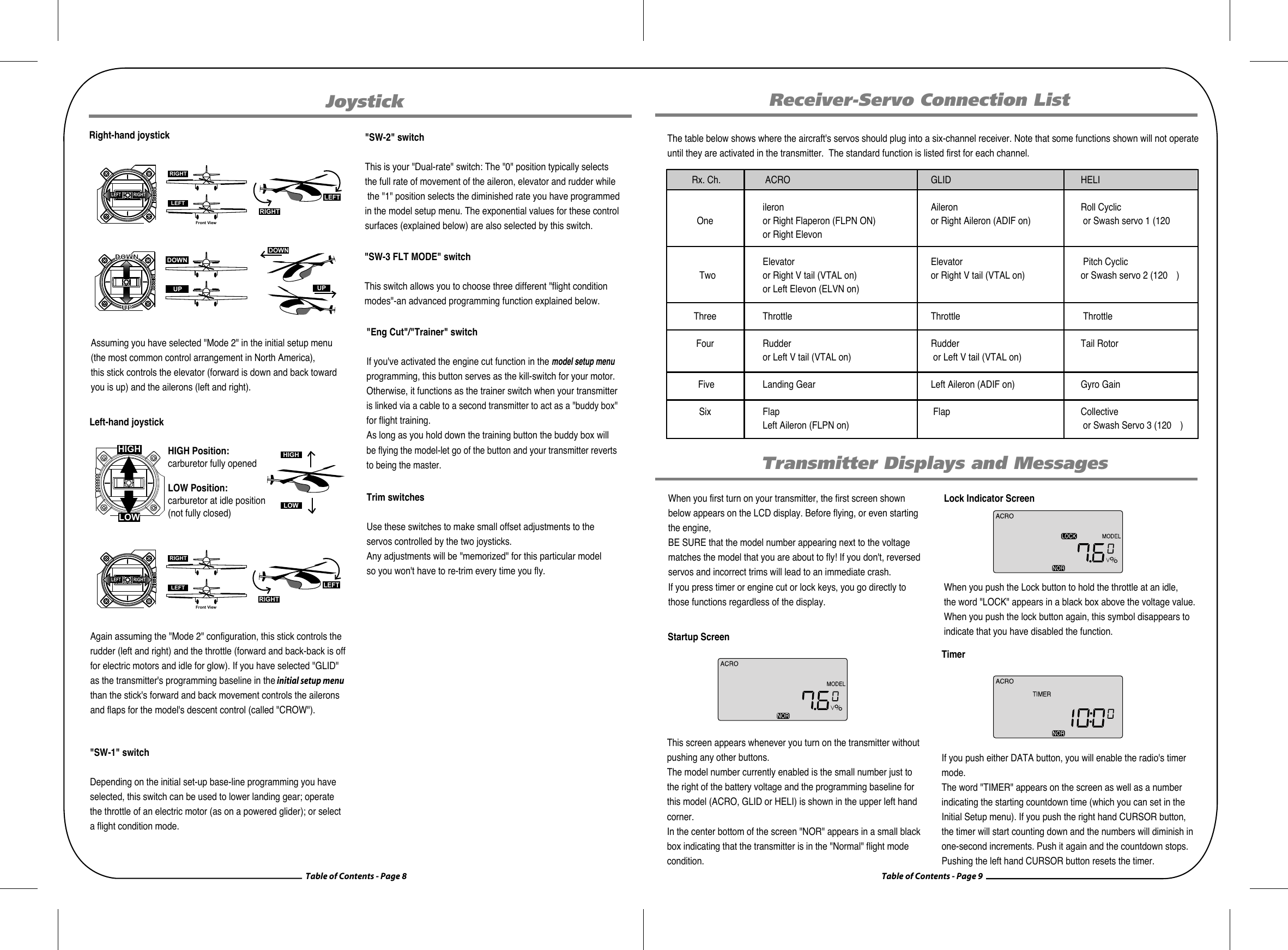
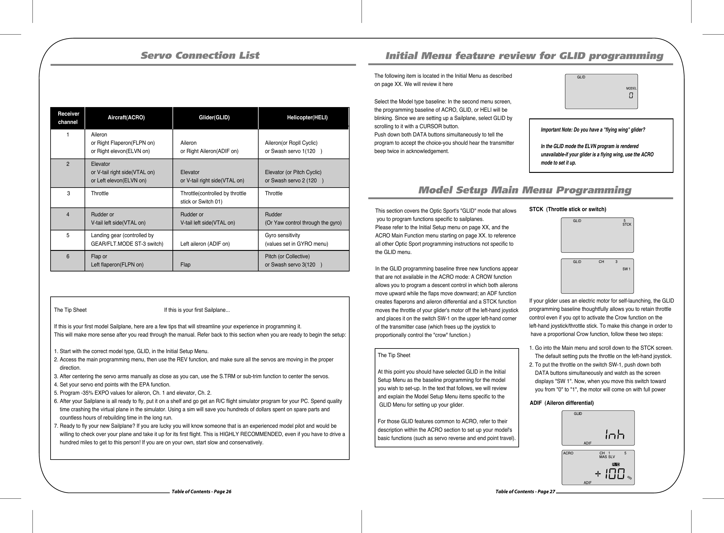
![Table of Contents - Page 10 Table of Contents - Page 11Menu Flow ListModel Number ChoiceModel TypeSwash Type, 90 or 120 (appears in Heli programming only)TimerMode type, 1 or 2Shift type, n or pReset to Factory defaultBefore you turn on the transmitter to begin programming one of themodel slots for your aircraft, refer to the servo connection chart AT DIRECTION to see how to plug the servos into their proper channel sockets in the receiver.Don't turn on the receiver in your model just yet-we'll tell you whento do so. First we'll get started setting up the aircraft in the Initial Setup program menu, then we'll continue into the Main Function menu to configure the servo responses and travels of your particular model. 1. Select a model slot: Hold down both EDIT buttons and slide the on-off switch to "on". The transmitter will beep, the red light will come on, and on the LCD screen you will find yourself in the first menu item of the initial setup menu. Under the word "MODEL" the number will be blinking on and off to get your attention. If this is the first model you are setting up in this transmitter, go ahead and accept this numbered slot by pushing the right-hand EDIT button to scroll down to the next menu item. When there are already models inputted, the number that comes up when you turn on the transmitter will be the last activated model slot. To change to a different slot, push on one of the CURSOR buttons to go to an empty slot (consult your list!) and then scroll to the next screen to automatically select it.2. Select the Model type programming baseline: In the second menu screen, the programming baseline of ACRO, GLID, or HELI will be blinking. Since we are setting up a powered aircraft, select ACRO by scrolling to it with a CURSOR button. Push down both DATA buttons simultaneously to tell the program to accept the choice-you should hear the transmitter beep twice in acknowledgement. Now push the right-hand EDIT button to move to the next menu screen.3. Heli Swash Plate: If you selected HELI as your model type, this screen will appear allowing you to select between NORMAL (90 degree mechanical) or 120 degree swash plate heli's by pressing one of the CURSOR buttons. Find out which one of these popular swash formats your helicopter uses and select it here. After selecting the appropriate swash type, continue down to the next menu item.Initial Setup Menu Programming for All AircraftWarning Display (Low voltage)When the battery's voltage drops to 6.6 volts, this number starts blinking on the screen and the transmitter begins to steadily beep. If your plane is up in the air when this happens, land immediately so you can recharge the battery.Warning Display (Flight Condition other than NOR)If you turn the transmitter on and it immediately starts to beep while displaying the word "ON" on the screen, one of the flight condition modes other than Normal is switched on. The symbol in the black box at the bottom of the screen indicates which switch (SW1 or SW3) needs to be reset to Normal.The Tip Sheet If this is your first Airplane¡If this is your first model Airplane, here are a few tips that willstreamline your experience in programming it. This will make more sense after you read through the manual. Refer back to this section when you are ready to begin the setup:1. Start with the correct model type, ACRO, in the Initial Setup Menu.2. Access the main programming menu, then use the REV function, and make sure all the servos are moving in the proper direction.3. After centering the servo arms manually as close as you can, use the S.TRM or sub-trim function to center the servos.4. Set your servo end points with the EPA function.5. Program -35% EXPO values for aileron, Ch. 1 and elevator, Ch. 2. 6. After your Plane is all ready to fly, put it on a shelf and go get an R/C flight simulator program for your PC. Spend quality time crashing the virtual plane in the simulator. Using a sim will save you hundreds of dollars spent on spare parts and countless hours of rebuilding time in the long run.7. Ready to fly your new Plane? If you are lucky you will know someone that is an experienced model pilot and would be willing to check over your plane and take it up for its first flight. This is HIGHLY RECOMMENDED, even if you have to drive a hundred miles to get to this person! If you are on your own, start slow and conservatively. Transmitter Displays and MessagesInitial Setup Menu Programming for All AircraftModel Select 0~9 [MODEL]Map of Basic Menu Functions MODEL Model select: choose on of ten model memories11 ACRO Acrobatic model mode 12 GLID Glider model mode 12 HELI Helicopter model mode 12 SWAH 90 Nomal suashplate(HELI only) 12SWAH 120 120* suashplat(HELI only) 12 TMER timer setup 14 MODE1 Transmitter mode 1 7 MODE2 Transmitter mode 2 7 SFT N Negative Transmit Shift 13 SFT P Oisitive Transmit Shift 13 RST Reset memory 14Model Type[ACRO] or [GLID]or[HELI]Seashplate type(HELI only)[90] [120]Time setup [TIMER XX]MODEL1, MODEL2Shift Dir.[SFT N][SFT P]Reset Memory [RST]](https://usermanual.wiki/Hitec-RCD/OPTIC6SP72/User-Guide-786026-Page-6.png)
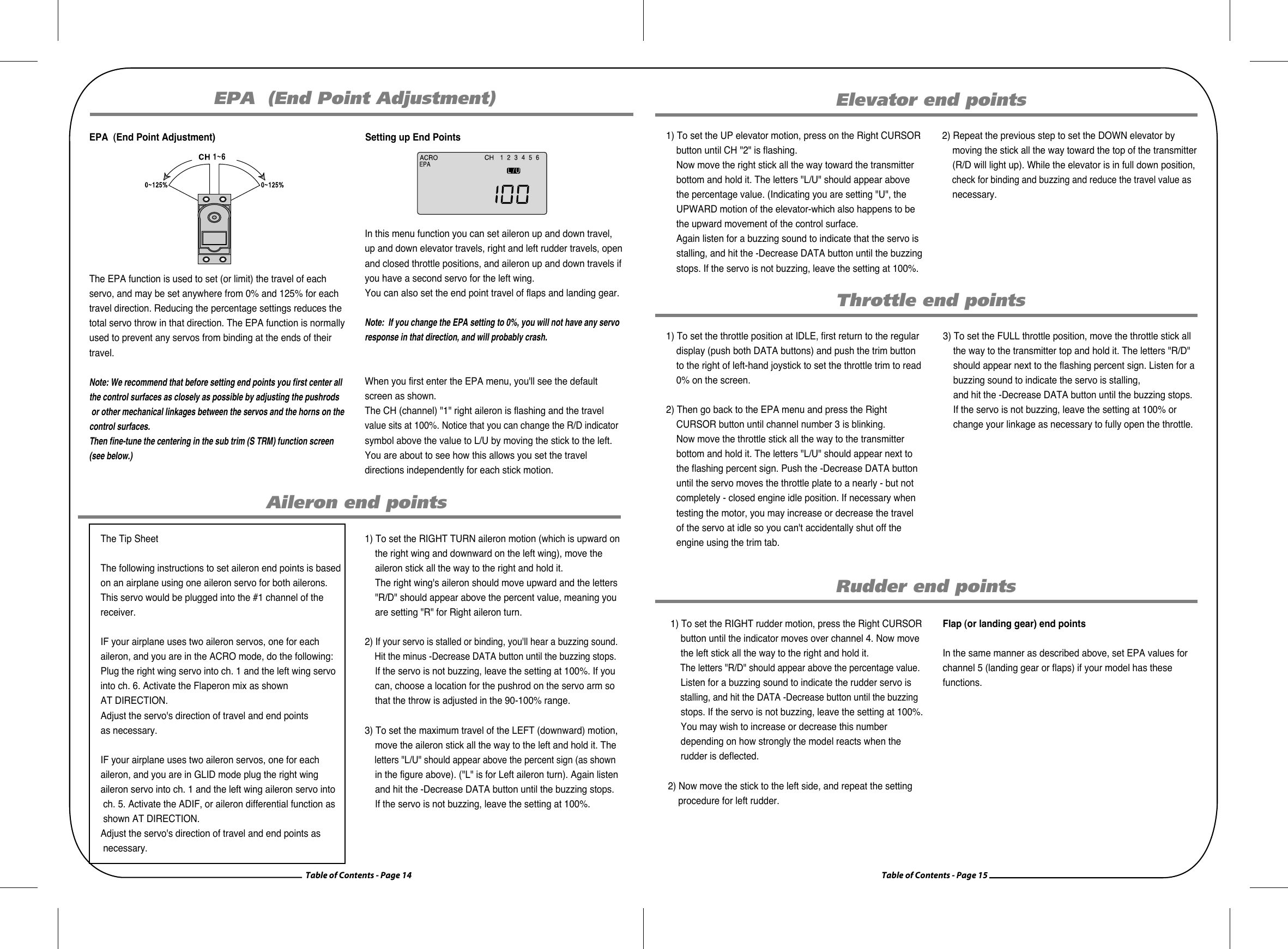
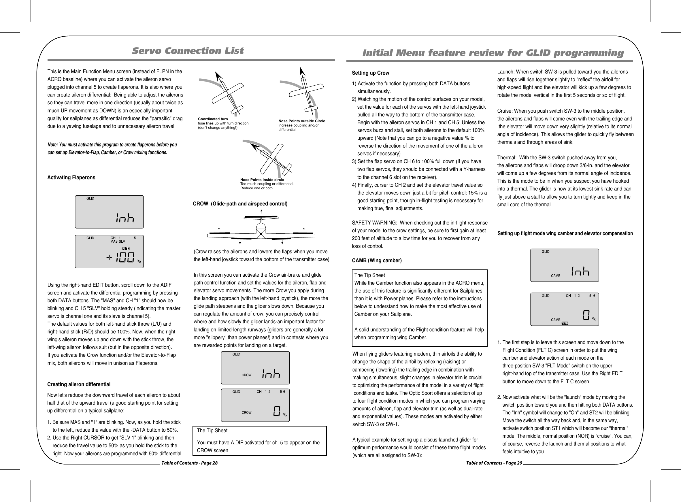
![Table of Contents - Page 12 Table of Contents - Page 13Model Setup Menu Programming for Powered Airplanes (ACRO) ACRO Functions Map Simple Aerobatic Aiplane Transmitter Setup 15 EPA End Point Adjust (servo travels) 27 D/R Dual Rates 27 EXP Exponential Settings 28 STRM Subtrim(Netural settings) 28 SREV SERVO Reverse 29 P.MX Programmable Mixer 29 ELVN Elevon mixing(tailless models) 29 FLPN Flaperon(combined flaps & ailerons) 30 VTAL V-tail mixing 30 A->R Rudder Coupling 31 E->F Elevator Flap Mixing 32 CUT Throttle Cut(engine shut off) 33 CAMB Camber(combined flaps & ailerons) 34FLT.C Flight condition(NOR, ST1, ST2, ST3) Gear Swich (SW-1) controls receiver CH5 FLT MODE(SW-3)switch Aft = CAMB OnVolage/Timer Displayhormal Display ModeEnd Point Adjust [EPA]Press both Edit DisplaDual Paste Set [D/R]Expon ential [EXP]Sub-Times [S.TRM]Servo Resbrsing [REV]Proo.Mik [PMX]Elevon Mik[ELVN]Flaperon Mik[FLPN]V-Tail[VTAL]Ail->Rud Mix[E-F]Elev->Flap Mix[E-F]Thrattle Cut[T.CUT]Camber[CAMB]Flapat aadiioii kal atl.atl.attiTo set up the Optic Sport to fly a particular model, you need to get into the radio's second programming menu: the model setup menu. In this menu you can program specific control functions;set servo throw direction; and set the values of servo travel, exponential rates and dual rates for the particular model you selected earlier in the initial setup menu. Go ahead and switch the transmitter on-you are now in the standard operating screen. In the upper left-hand corner it will say "ACRO" and to the right there will be a large number telling you the state of the battery voltage (such as 7.2 v) and a smaller single-digit number indicating the model slot the radio is currently opened to. There will also be a little black box at the bottom of the screen with the symbol "NOR". This indicates that the system is currently in the "normal" flight condition mode. Later, we will show you how to activate the flight condition modes-and it is here on the screen where you will be told which mode is currently active.Now push down both EDIT buttons at the same time. The following menu items will appear as you scroll down the list by pushing down the right-hand EDIT button:The Tip SheetWhen programming a model for the first time, start with setting servo direction and then activate any mix's needed like Flaperon, Elevon or Aileron/Rudder. Next, progress through adjusting subtrim and setting end point travel of each servo; then set exponential and dual rate values. Transmitter Displays and Messages4. Configure the countdown timer: Now you are at the TIMER menu item with a number blinking away at you-its 10 (minutes) by default. If you want to set a timer value, go to AT DIRECTION for more information on using the timer function. Otherwise, move down to the next menu item. The Tip SheetThe Optic Sport features a powerful option allowing you toselect between a Negative or Positive signal transmit shift. This allows you to use any brand of modern FM receiver. As a general rule, Futaba¢ç receivers are "Negative" shift, while JR¢ç, Airtronics¢ç and most Multiplex receivers are all Positive shift. All models of Hitec receivers have been offered in both shift versions, while newer Hitec receivers are now "auto shift selectable" and automatically know what the shift the transmitter is. 5. Select the control's Mode configuration: Under the word "MODE", the number "2" is blinking by default. Go ahead and accept mode 2 by pushing the right-hand EDIT button to continue to the next screen. Of course, if you are used to the mode 1 configuration (elevator on the left stick, throttle on the right), then select number 1. Other changes to accommodate Mode 1 flyers must be done to the transmitter. Please refer to AT DIRECTION for more information.6. Select the signal shift: As indicated by the "SFt" symbol on the screen we are now in the shift selection menu. The blinking default selection is "n", meaning negative shift. If your receiver is marked "positive" shift, push one of the CURSOR buttons so that a "P" starts blinking. Then scroll to the next screen.7. Reset Screen: In this screen you should now see "GLID" in the upper left hand corner and the number you selected under "MODEL". You should also see a tiny "RST" blinking in the lower right hand corner of the screen. This means RESET-and if you push both DATA buttons at the same time that's exactly what will happen: You will undo all the initial programming we just did, returning all the programming to the factory's default settings!Now push the Right EDIT button to scroll right back where we started when we first turned on the transmitter. We are now done with the initial setup programming of your aircraft, so switch off the transmitter. When you switch it on again without holding down both EDIT buttons the transmitter will open up in the current model slot (the one we just programmed) with all the initial settings we just programmed in effect.The Tip SheetAt this point you have selected the type of model ACRO, GLID or HELI, you wish to set-up. In the manual text that follows, we will review and explain the Model Setup Menu of the three different model types. The first is ACRO, followed by GLID, then HELI. All ACRO features will be described in detail within the ACRO section. Within the following GLID and HELI sections, only features exclusive to GLID and HELI programming will be described in detail. For those GLID and HELI features common to ACRO, we will refer you to their description within the ACRO section.](https://usermanual.wiki/Hitec-RCD/OPTIC6SP72/User-Guide-786026-Page-7.png)
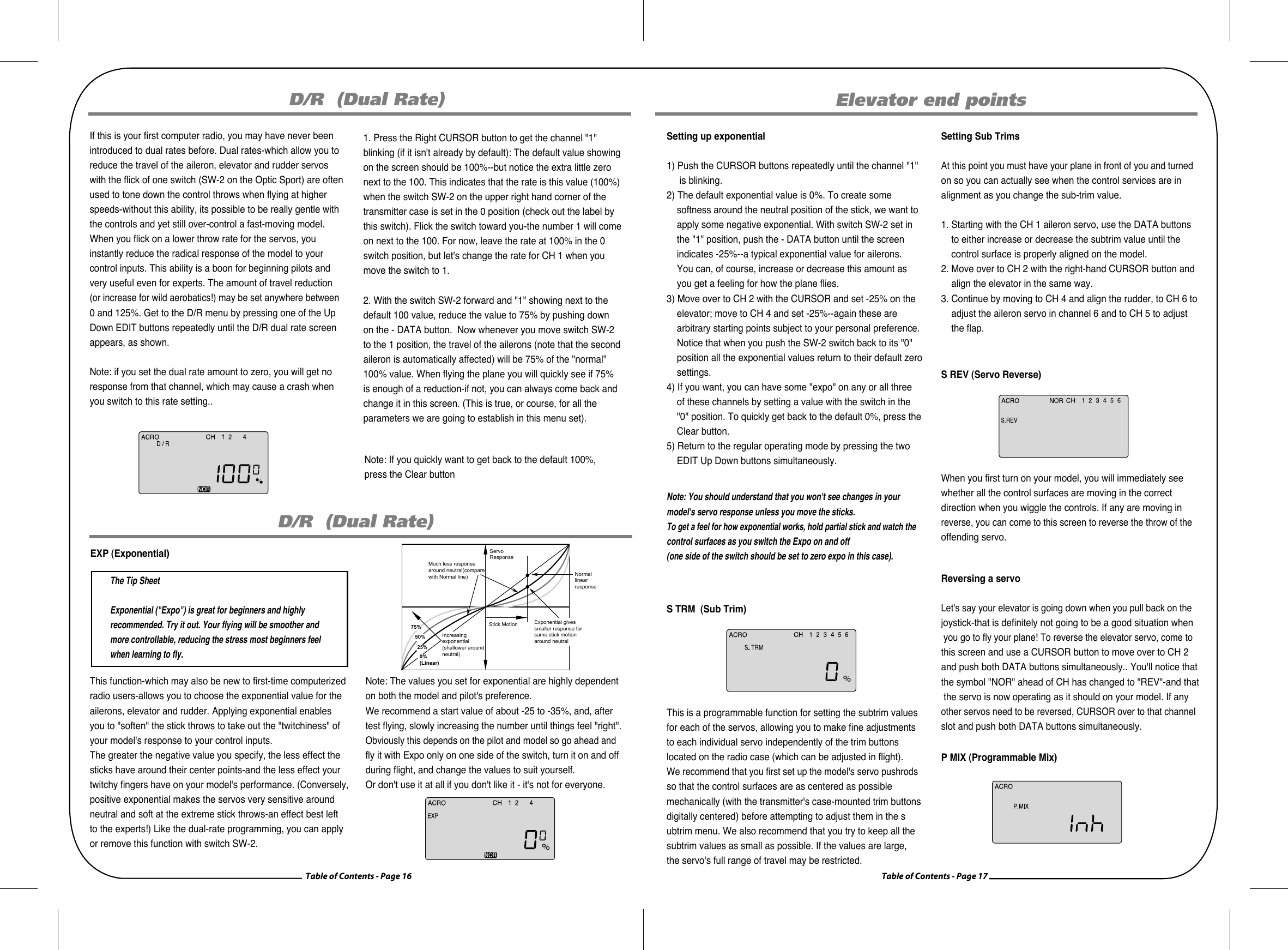
![Table of Contents - Page 18 Table of Contents - Page 19ELVN (Elevon mix)ELVN (Elevon mix)front viewIf you are setting up a tail-less delta or flying wing aircraft, you can use this program to activate the pre-programmed elevon mix that mixes the output on the CH 1 aileron and CH 2 elevator servo channels. (As you will notice in the servo connection chart, you plug one aileron servo in the receiver's channel 1 slot and the other aileron servo into channel 2-the slot that usually feeds the elevator.) This is necessary because on these wing types the ailerons must double as elevators. Note: When you activate ELVN, note that flaperon and V-tail mixing are rendered unavailable by the radio. 2) Now set the amount (and direction if necessary as noted a bove) of each servo-both as ailerons and as elevators. Because flying wings are extraordinarily pitch sensitive (because the elevator control surface is so close to the airframe's center of gravity), you generally need the elevator travel to be much less than that of the ailerons. We create this type of differential in the next step. 3) For now, leave the "MAS 1" percentage value at the default 100% (unless your servo is stalling) and then CURSOR over to the "SLV 1" where you will also leave the default value at 100%. Push the CURSOR button again to light up "MAS 2" and reduce the value to +40%; CURSOR over to "SLV 2" and reduce that value to +40% as well. If one of the servo's travel directions isn't correct in the elevator function, simply make this servo's travel volume a negative -40%. 4) When you fly the model, if you find that this 40% reduction isn't enough to take out "pitchiness", land and further reduce the travel volume. To tone down the roll response, you can reduce the endpoints of the aileron travel or set up dual-rates on channel one as described in the setup of Model-1 above.[Insert graphic of aileron differential and flaperons function]This function activates another aileron servo (on channel 6 when in the ACRO menu) so that both ailerons can be slaved together to create a flaperon. This allows both ailerons to move together as flaperons for camber control or independently as usual for roll control. In this menu you can also set individualtravel values-upward and downward-for each aileron to create aileron differential. Being able to move an aileron less in one direction (usually downwards) helps reduce yaw in turns (and therefore unnecessary drag.) FLPN (Flaperon)Setting up elevons1) Activate the elevon function by pressing both DATA buttons when you are in the ELVN screen. Now check your model to see what happens when you move the right-hand joystick side-to-side-the ailerons should go up and down appropriately.Move the joystick forward and back to see if the ailerons bothrespond correctly as elevators. If necessary, go to the S REVscreen to reverse an offending servo.IMPORTANT NOTE: It is possible due to the particular configuration of your servos that servo reverse won't fix the problem-you may get the ailerons working properly but not the elevator response on both servos. Don't worry: You can fix this problem in the elevon programming by changing one of the servo travel volumes to a negative value.CH1 CH2Aileron OperationElevator OperationP MIX (Programmable Mix)In this screen you can activate the ability of the Optic 6 Sport to create a custom-made, programmable mix of any two servochannels in which one servo is electronically "slaved" to another. This is a relatively advanced function.The program also provides a way to change the value of the response of the slave servo to that of the master. For example you could slave the elevator servo to the throttle channel so that when you increase the throttle, a slight downward movement of the elevator kicks in to automatically compensate for any up-pitching due to the increased thrust. Another typical mix might be to mix rudder with the throttle to reduce yawing. The Optic Sport's mixing program also offers an advanced function (call TRM P MIX) that, when activated, allows both servos to be trimmed by the same master servotrim button on the radio case-a useful option when, for example, you are using two servos to control a split elevator. We will show you how to set up these examples below.Set up a throttle-to-rudder mixWhen you apply throttle to a powerful motor, the resultanttorque from the spinning propeller often tends to make theplane yaw to one side (usually to the left).This not only interferes with precision aerobatic maneuvers, but it makes it difficult to keep the model aligned with the runway during a full-power takeoff. To reduce the "pilot load" of having to correct the yaw with your left thumb on the rudderstick, you can use the P-Mix program function to automatically mix a proportional amount of rudder with an increase of throttle.Now let's set it up:shows "CH" with "MAS" blinking beneath. If, instead, a percentage value is blinking use the right-hand CURSORbutton to scroll over until you get this "CH" and "MAS" configuration. One of the servo channel numbers will also be showing-the default is "1". 2) To make the throttle the master channel, push a DATA button to light up "3". Now push the right-hand CURSOR once more: "SLV" will light up with a number. Use a DATA button tochange this number to "4". Now the rudder channel is slaved to the throttle channel. 3) Push the CURSOR button again: MAS 3 and a percentage value will be blinking. Use the DATA buttons to set the value of rudder travel to throttle travel-change to a negative value to move the rudder in the opposite direction if necessary. You won't likely need more than 15% to counteract the torque,but only flight-testing will tell for sure. 1) Enter the Main Function menu and scroll down to the P MIX screen with the EDIT buttons. Activate the function by pressing both DATA buttons-"Inh" will turn off and the default screen P-Mix trim:Set up a double-servo elevator with coordinated trim functionThe Optic 6 Sport offers an unusually sophisticated nuance with its P-MIX function: the ability to trim two servos simultaneously. This is especially useful if you are using two elevator servos (one to each half of the elevator). In flight,if the elevator needs to be trimmed, you can make the adjustment with the trim button next to the right-hand joystick on the case instead of having to enter the model setup programming in order to trim the servos independently. Lets set this example up: 1) Enter the P MIX screen and select the master and slave servos (2 and 5 on this radio for split elevators) and then selectthe travel value (most likely 100% unless your servo pushrodsare not set up exactly the same way). 2) Now use the Right CURSOR button to move to the P MIX screen where "TRM" is blinking. The default setting is "OFF"-turn it to "ON" by pressing the CLEAR button. 3) Exit the menu and you now have a split elevator with trimfunction.](https://usermanual.wiki/Hitec-RCD/OPTIC6SP72/User-Guide-786026-Page-10.png)
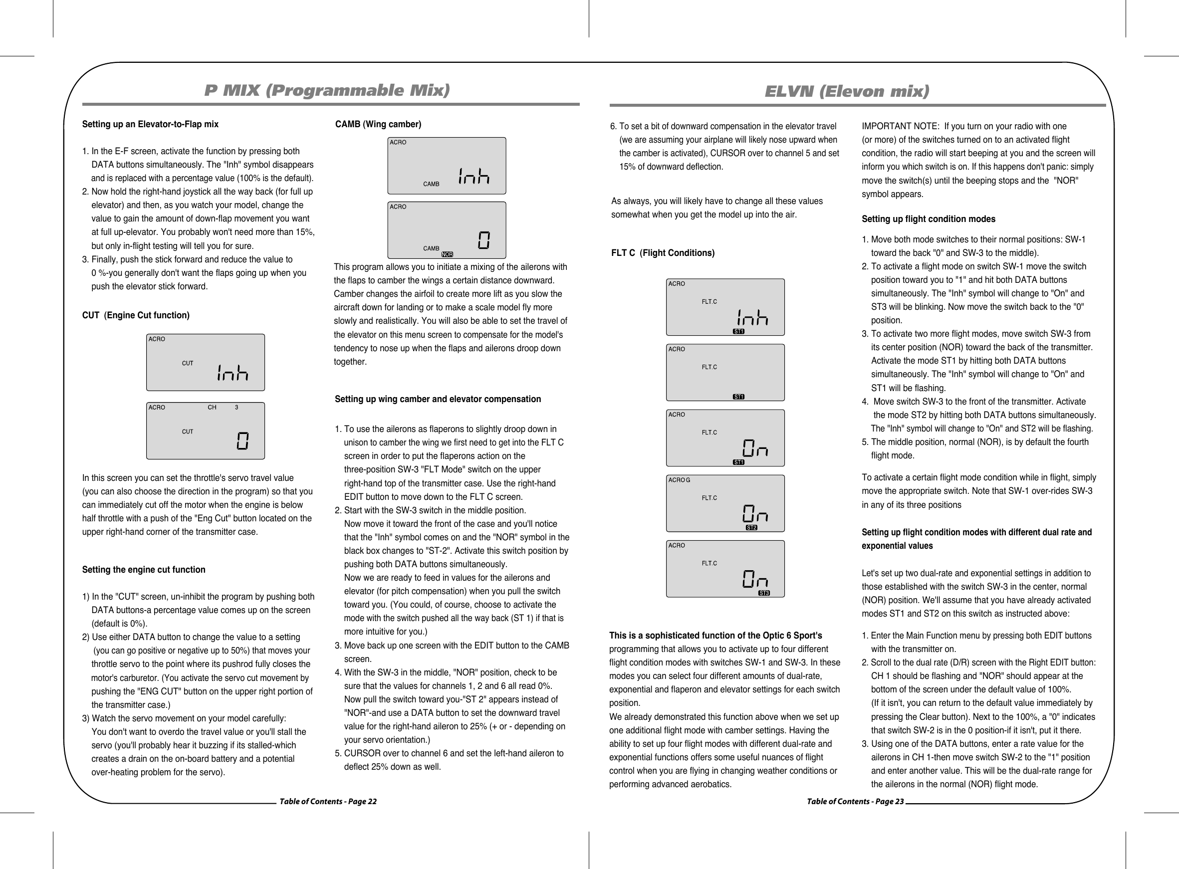
![Table of Contents - Page 20 Table of Contents - Page 21ELVN (Elevon mix)Setting up a V-Tail1) Activate the program by pushing down both DATA buttons simultaneously-the screen will change from "Inh" to a % value. 2) With your model turned on, check your servo travel directions-both rudder and elevator channels-to be sure they are correct. Go to the S REV screen if necessary to make the correction. 3) For a basic V-tail setup, you can leave all the values at 100% so that the tails will move together as an elevator, but not independently as rudders. 4) If you wish to add rudder control to help coordinate the turns, proceed this way: CURSOR over until MAS 4 is blinking than change the value as necessary (you may have to go into negative values) to make the master servo on channel 4 move appropriately (see the illustration AT DIRECTION). Now CURSOR over to SLV 4 and change the value of the slave servo on channel 2 as necessary.Setting up a rudder-to-aileron mix1) In the A-R screen, activate the function by pressing both DATA buttons at once. The "Inh" symbol disappears and is replaced with a percentage value (100% is the default). 2) Hold the right-hand joystick to the left, and use the - DATA button to reduce the value to a reasonable mix to begin with, say 25%. 3) You're not done yet, though-we have the same issue with the stick we encountered in the end point adjustment (EPA) screen. If you move the aileron joystick to the right, the value goes back to the default 100% setting. Hold the stick to the right and reduce the value to 25% here as well. 4) Now watch the rudder move as you move the joystick right and left-as the right wing's aileron moves up, the rudder should swing about one-quarter of its travel to the right-and to the left with left-hand stick travel.The optimum value of the mix can only be determined by flyingthe model: If the nose of the airplane yaws to the right when you bank left, there is too little coupling-increase the rudder travel value. If it veers to the left (with the bank) there is toomuchThis program allows you to set a certain amount of elevator-to-flap mixing so that the flaps (or flaperons if you've activated this mix) move downward slightly when you pull back on the elevator stick. This is a favorite mix for pylon racing and 3-D aerobatics as a downward flap movement combined with up-elevator movement enables the plane to snap-turn more quickly. E-F (Elevator-Flap mix)A-R (Aileron-Rudder mix)This pre-programmed aileron-rudder mix allows you to slave a certain amount of rudder movement with the movement of the ailerons to gain automatically coordinated turns. In addition to aileron differential, this mix reduces the yawing of the fuselage when the ailerons bank the wing. This mix is especially useful for making the turns of slower-flying scale models appear more realistic. UP elevatorDOWN flap or flaperonP MIX (Programmable Mix)Setting up flaperons1) Activate the program by pushing both DATA buttons-the "Inh" symbol changes to the default 100% value. With your model turned on, test the ailerons by moving the joystick to the right and to the left: To the right, the right-hand aileron should go up while the left-hand aileron goes down. If this isn't happening, go to the S REV screen and reverse the offending aileron. 2) Now check the travel volume: If the servos are stalling at their maximum throw, turn down the value in the EPA screen (or move the pushrod further up on the aileron horn to physically reduce the throw). Create aileron differentialNow let's create some aileron differential so that the ailerons move about twice as much upward than downward. Notice that the "MAS" (master) symbol is blinking along with channel 1 and the % sign. This means that we can change the travel value of the right-hand aileron (the master servo). Also notice that L/U is showing, meaning the value will changeonly for left-stick throw. 1) Reduce the downward movement to 50% by pushing down the left-hand DATA button. Now move the stick to the right and you will see R/D appear along with the default 100% throw value. 2) To create similar differential on the left hand servo (the slave) push down the right-hand CURSOR button once-now the "1" and the "SLV" symbols will be blinking. This time leave the L/U stick position at 100%, then move the stick to the right to light up R/D and decrease the downward travel value to 50% with the left-hand -DATA button. Now we have differential-each aileron should be movingdownward about half the amount it moves upward. You will likely have to adjust these values once you fly the plane and observe the yaw of the fuselage as you roll the aircraft:This is another built-in mixing program available in the Optic Sport that mixes the rudder and elevator servos for controlling V-tailed aircraft. Similar to elevon programming, the two surfaces can move up and down together (for elevator control) or opposite (for rudder control in this case). Note: When you select V.TAL, the ELVN program is rendered unavailable.V TAL (V-Tail)[Insert V-Tail illustration]Nose Points outside Circleincrease coupling and/ordifferentialCoordinated turnfuse lines up with turn direction(don't change anything!)Nose Points inside circleToo much coupling or differential.Reduce one or both.CH2 CH4 CH2 CH4Up Elevator Right Rudder (view from rear)](https://usermanual.wiki/Hitec-RCD/OPTIC6SP72/User-Guide-786026-Page-11.png)
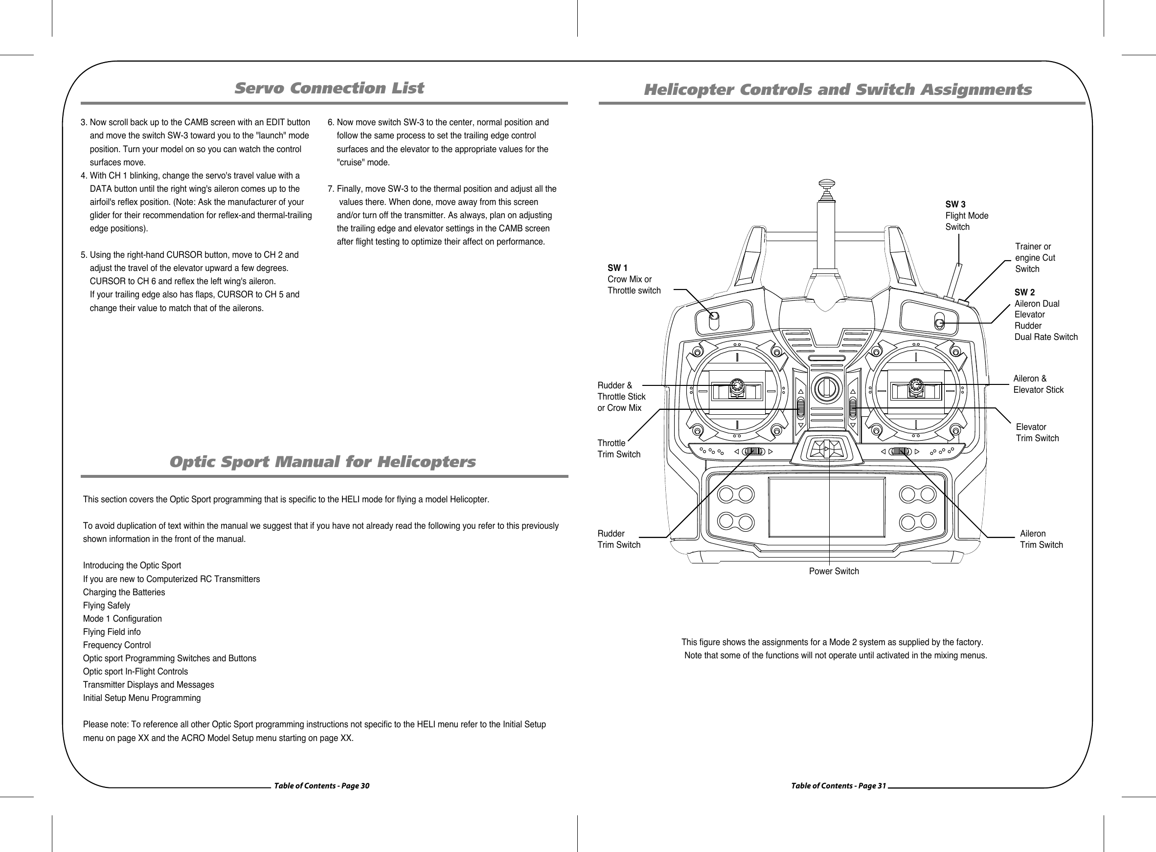
![Table of Contents - Page 24 Table of Contents - Page 25Sailplane Controls and Switch AssignmentsP MIX (Programmable Mix)Model Setup Menu Programming for Sailplanes (GLID)4. To establish a second set of dual rates for the ailerons in flight condition mode ST1, move the switch SW-3 to the back of the case: ST1 appears. Now set a dual rate when the switch SW-2 in the "0" position and then in the "1" position.5. To establish a third set of dual rates for the ailerons in flight condition mode ST2, move the switch SW-3 to the front of the case: ST2 appears. Now set a dual rate when the switch SW-2 in the "0" position and then in the "1" position.To avoid duplication of text within the manual we suggest that if you have not already read the following you refer to thispreviously shown information in the front of the manual.Introducing the Optic SportIf you are new to Computerized RC TransmittersCharging the BatteriesFlying SafelyMode 1 ConfigurationFlying Field infoFrequency ControlOptic Sport Programming Switches and ButtonsOptic Sport In-Flight ControlsTransmitter Displays and MessagesInitial Setup Menu Programming6. If you wish to set dual-rate ranges for the elevator and the rudder follow the last three steps above-entering in the values in elevator CH 2 and then in rudder CH 4.7. To establish the two additional flight mode exponential settings, scroll to the EXP screen and follow essentially the same process outlined above for setting the dual-rate ranges. (Note that both the dual-rate and exponential settings are toggled on the same switch: SW-2). GLID FUNCTIONS MAP Simple Aerobatic Aiplane Transmitter Setup 15 EPA End Point Adjust (servo travels) 27 D/R Dual Rates 27 EXP Exponential Settings 28 STRM Subtrim(Netural settings) 28 SREV SERVO Reverse 29 P.MX Programmable Mixer 29 ELVN Elevon mixing(tailless models) 29 FLPN Flaperon(combined flaps & ailerons) 30 VTAL V-tail mixing 30 A->R Rudder Coupling 31 E->F Elevator Flap Mixing 32 CUT Throttle Cut(engine shut off) 33 CAMB Camber(combined flaps & ailerons) 34FLT.C Flight condition(NOR, ST1, ST2, ST3) Gear Swich (SW-1) controls receiver CH5 FLT MODE(SW-3)switch Aft = CAMB OnVolage/Timer Displayhormal Display ModeEnd Point Adjust [EPA]Press both Edit DisplaDual Paste Set [D/R]Expon ential [EXP]Sub-Times [S.TRM]Servo Resbrsing [REV]Proo.Mik [PMX]Elevon Mik[ELVN]Flaperon Mik[FLPN]V-Tail[VTAL]Ail->Rud Mix[E-F]Elev->Flap Mix[E-F]Thrattle Cut[T.CUT]Camber[CAMB]Flapat aadiioii kal atl.atl.attiTrainer orengine Cut SwitchSW 2Aileron Dual ElevatorRudderDual Rate SwitchSW 1Crow Mix orThrottle switchRudder & Throttle Stickor Crow MixAileron & Elevator StickThrottle Trim SwitchElevator Trim SwitchRudder Trim SwitchAileron Trim SwitchPower SwitchSW 3Flight Mode SwitchThis figure shows the assignments for a Mode 2 system as supplied by the factory. Note that some of the functions will not operate until activated in the mixing menus.](https://usermanual.wiki/Hitec-RCD/OPTIC6SP72/User-Guide-786026-Page-13.png)
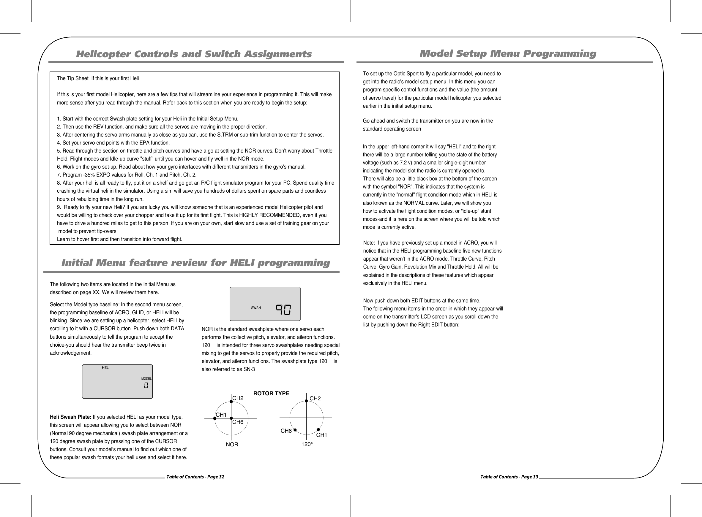
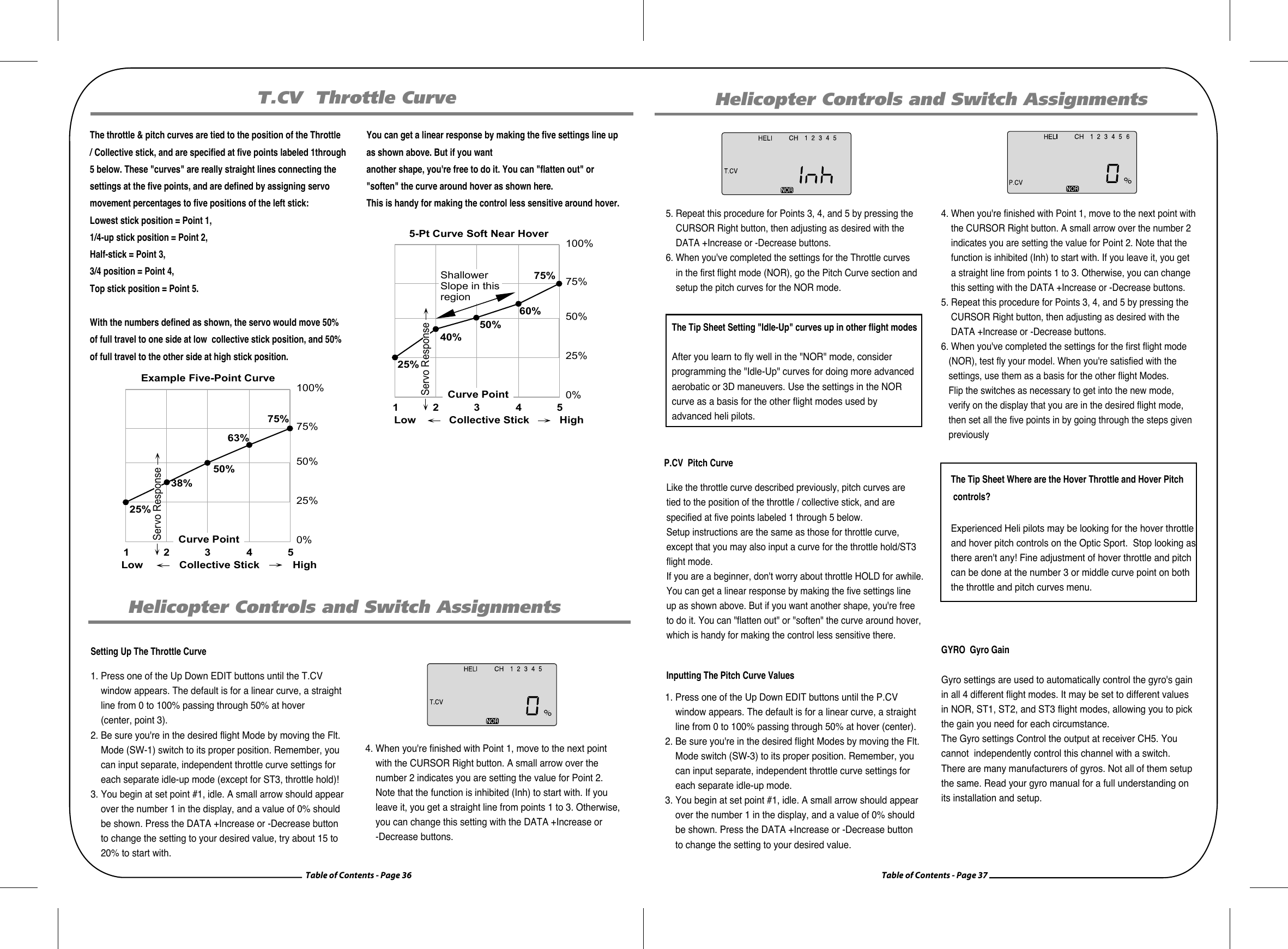
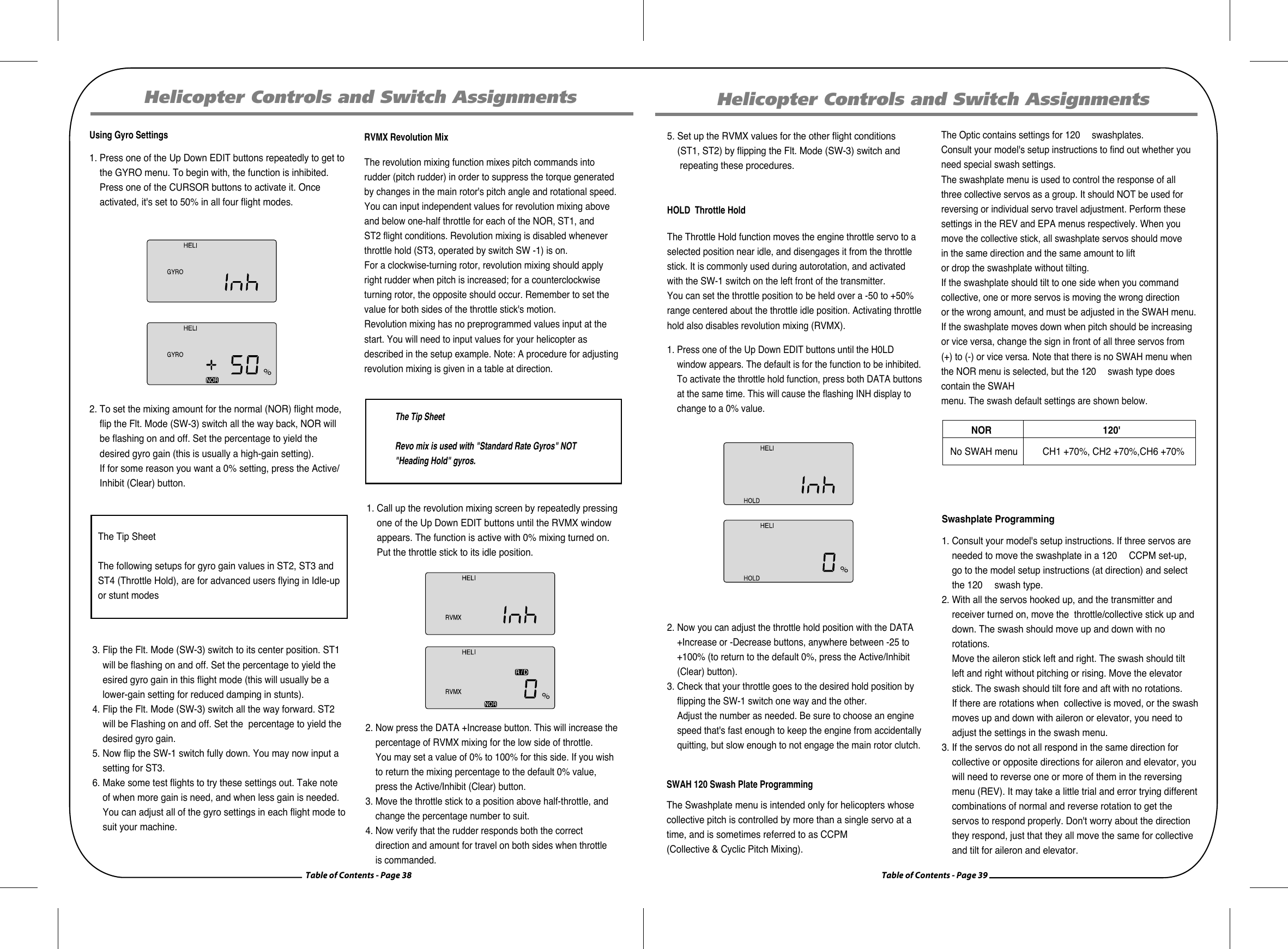
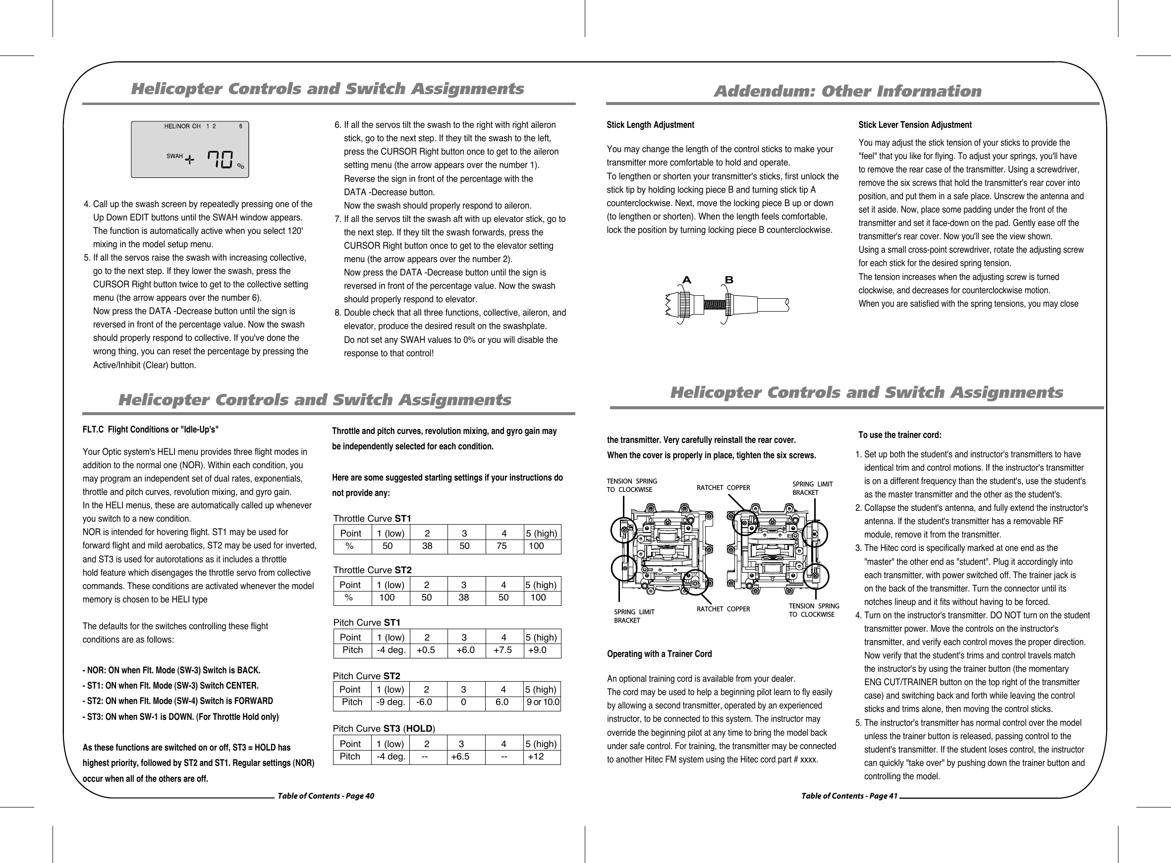
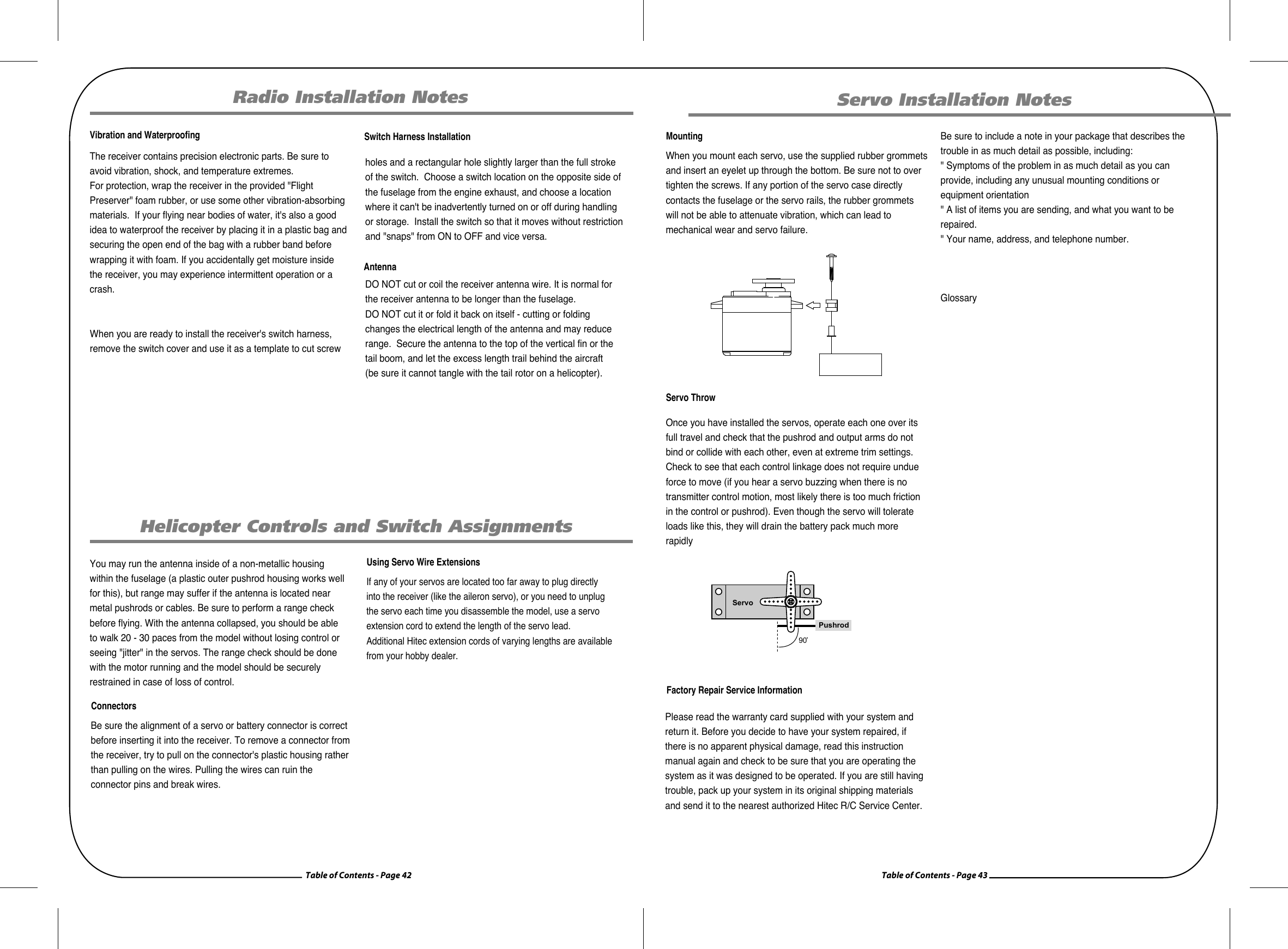
![Table of Contents - Page 34 Table of Contents - Page 35Helicopter Controls and Switch AssignmentsHelicopter Controls and Switch AssignmentsThis section describes how to use the Optic helicopter functions (model type HELI). Descriptions of the other functions, such as endpoints, dual rates, expo, etc., are contained in the aircraft (ACRO) sectionThe Tip Sheet The Two Fundamental Types of Helicopter's: Fixed Pitch and Collective PitchThere are two fundamental types of model heli's, fixed pitch and collective pitch. The fixed pitch heli is simpler to operate and has fewer moving parts as the motor or engine RPM controls the speed of the "fixed" pitch blades of the heli.For this fixed pitch function you will use the Throttle curve function of the Optic Sport, but not the Pitch curve function.The other, more common, collective pitch setup uses a mix within the electronics of the radio transmitter to combine the throttle RPM with the adjustable "pitch" or angle of the heli's blades. Both Throttle curves and Pitch curves functions of the Optic Sport are used to fine-tune the performance of a collective pitch heli. The Two fundamental types of power: Electric and Glow There are some subtle, but important differences in the setup methods for glow- versus electric-powered heli's: If your Heli is powered by a glow engine: 1. A servo plugged into the Ch. 3 slot of the receiver controls the carburetor throttle plate of the engine.2. Glow heli's also have their own "on-board" battery to power the receiver, gyro and servos.If your Heli is powered by an electric motor:1. A proportional ESC (Electronic Speed Control) is plugged into the Ch. 3 receiver slot to control the RPM of the motor. The Speed Control may have settings that need to be programmed so check the Speed Controller manual. 2. Instead of a fuel tank, a large battery pack provides power to the motor, as well as powering the receiver, gyro and servos through the BEC (Battery Eliminator Circuit) of the ESC (Electronic Speed Control).Helicopter Controls and Switch AssignmentsHelicopter Functions Map Helicopter Setup Example 15 EPA End Point Adjust (servo travels) 27 D/R Dual Rates 27 EXP Exponential Settings 28 STRM Subtrim(Netural settings) 28 SREV SERVO Reverse 29 P.MX Programmable Mixer 29 ELVN Elevon mixing(tailless models) 29 FLPN Flaperon(combined flaps & ailerons) 30 VTAL V-tail mixing 30 A->R Rudder Coupling 31 E->F Elevator Flap Mixing 32 CUT Throttle Cut(engine shut off) 33 CAMB Camber(combined flaps & ailerons) 34FLT.C Flight condition(NOR, ST1, ST2, ST3) Gear Swich (SW-1) controls receiver CH5 FLT MODE(SW-3)switch Aft = CAMB OnVolage/Timer DisplayNormal Display ModeEnd Point Adjust [EPA]Press both Edit DisplaDual Paste Set [D/R]Expon ential [EXP]Sub-Times [S.TRM]Servo Resbrsing [S.REV]Prog.Mix [PMX]Thnottle Curve[R.CV]Pitch curve[R.CV]Gyro setting[GYRO]Revolution[RVMX]Throttle Hold[HOLD]Throttle Cut[TCUT]Swashplate[SWAH]Flight Conditions FLT.C](https://usermanual.wiki/Hitec-RCD/OPTIC6SP72/User-Guide-786026-Page-18.png)